WO2016143402A1 - 情報処理装置及び情報処理方法 - Google Patents
情報処理装置及び情報処理方法 Download PDFInfo
- Publication number
- WO2016143402A1 WO2016143402A1 PCT/JP2016/052296 JP2016052296W WO2016143402A1 WO 2016143402 A1 WO2016143402 A1 WO 2016143402A1 JP 2016052296 W JP2016052296 W JP 2016052296W WO 2016143402 A1 WO2016143402 A1 WO 2016143402A1
- Authority
- WO
- WIPO (PCT)
- Prior art keywords
- parts
- information processing
- processing apparatus
- information
- arrangement
- Prior art date
- Legal status (The legal status is an assumption and is not a legal conclusion. Google has not performed a legal analysis and makes no representation as to the accuracy of the status listed.)
- Ceased
Links
Images


Classifications
-
- A—HUMAN NECESSITIES
- A63—SPORTS; GAMES; AMUSEMENTS
- A63B—APPARATUS FOR PHYSICAL TRAINING, GYMNASTICS, SWIMMING, CLIMBING, OR FENCING; BALL GAMES; TRAINING EQUIPMENT
- A63B24/00—Electric or electronic controls for exercising apparatus of preceding groups; Controlling or monitoring of exercises, sportive games, training or athletic performances
- A63B24/0003—Analysing the course of a movement or motion sequences during an exercise or trainings sequence, e.g. swing for golf or tennis
-
- A—HUMAN NECESSITIES
- A61—MEDICAL OR VETERINARY SCIENCE; HYGIENE
- A61B—DIAGNOSIS; SURGERY; IDENTIFICATION
- A61B5/00—Measuring for diagnostic purposes; Identification of persons
- A61B5/68—Arrangements of detecting, measuring or recording means, e.g. sensors, in relation to patient
- A61B5/6801—Arrangements of detecting, measuring or recording means, e.g. sensors, in relation to patient specially adapted to be attached to or worn on the body surface
- A61B5/6813—Specially adapted to be attached to a specific body part
- A61B5/6829—Foot or ankle
-
- A—HUMAN NECESSITIES
- A43—FOOTWEAR
- A43B—CHARACTERISTIC FEATURES OF FOOTWEAR; PARTS OF FOOTWEAR
- A43B17/00—Insoles for insertion, e.g. footbeds or inlays, for attachment to the shoe after the upper has been joined
-
- A—HUMAN NECESSITIES
- A43—FOOTWEAR
- A43B—CHARACTERISTIC FEATURES OF FOOTWEAR; PARTS OF FOOTWEAR
- A43B3/00—Footwear characterised by the shape or the use
- A43B3/34—Footwear characterised by the shape or the use with electrical or electronic arrangements
-
- A—HUMAN NECESSITIES
- A61—MEDICAL OR VETERINARY SCIENCE; HYGIENE
- A61B—DIAGNOSIS; SURGERY; IDENTIFICATION
- A61B5/00—Measuring for diagnostic purposes; Identification of persons
- A61B5/103—Measuring devices for testing the shape, pattern, colour, size or movement of the body or parts thereof, for diagnostic purposes
- A61B5/1036—Measuring load distribution, e.g. podologic studies
-
- A—HUMAN NECESSITIES
- A61—MEDICAL OR VETERINARY SCIENCE; HYGIENE
- A61B—DIAGNOSIS; SURGERY; IDENTIFICATION
- A61B5/00—Measuring for diagnostic purposes; Identification of persons
- A61B5/103—Measuring devices for testing the shape, pattern, colour, size or movement of the body or parts thereof, for diagnostic purposes
- A61B5/11—Measuring movement of the entire body or parts thereof, e.g. head or hand tremor or mobility of a limb
-
- A—HUMAN NECESSITIES
- A61—MEDICAL OR VETERINARY SCIENCE; HYGIENE
- A61B—DIAGNOSIS; SURGERY; IDENTIFICATION
- A61B5/00—Measuring for diagnostic purposes; Identification of persons
- A61B5/103—Measuring devices for testing the shape, pattern, colour, size or movement of the body or parts thereof, for diagnostic purposes
- A61B5/11—Measuring movement of the entire body or parts thereof, e.g. head or hand tremor or mobility of a limb
- A61B5/1126—Measuring movement of the entire body or parts thereof, e.g. head or hand tremor or mobility of a limb using a particular sensing technique
- A61B5/1127—Measuring movement of the entire body or parts thereof, e.g. head or hand tremor or mobility of a limb using a particular sensing technique using markers
-
- A—HUMAN NECESSITIES
- A61—MEDICAL OR VETERINARY SCIENCE; HYGIENE
- A61B—DIAGNOSIS; SURGERY; IDENTIFICATION
- A61B5/00—Measuring for diagnostic purposes; Identification of persons
- A61B5/68—Arrangements of detecting, measuring or recording means, e.g. sensors, in relation to patient
- A61B5/6801—Arrangements of detecting, measuring or recording means, e.g. sensors, in relation to patient specially adapted to be attached to or worn on the body surface
- A61B5/6813—Specially adapted to be attached to a specific body part
- A61B5/6825—Hand
-
- A—HUMAN NECESSITIES
- A61—MEDICAL OR VETERINARY SCIENCE; HYGIENE
- A61B—DIAGNOSIS; SURGERY; IDENTIFICATION
- A61B5/00—Measuring for diagnostic purposes; Identification of persons
- A61B5/68—Arrangements of detecting, measuring or recording means, e.g. sensors, in relation to patient
- A61B5/6887—Arrangements of detecting, measuring or recording means, e.g. sensors, in relation to patient mounted on external non-worn devices, e.g. non-medical devices
- A61B5/6895—Sport equipment
-
- A—HUMAN NECESSITIES
- A63—SPORTS; GAMES; AMUSEMENTS
- A63B—APPARATUS FOR PHYSICAL TRAINING, GYMNASTICS, SWIMMING, CLIMBING, OR FENCING; BALL GAMES; TRAINING EQUIPMENT
- A63B24/00—Electric or electronic controls for exercising apparatus of preceding groups; Controlling or monitoring of exercises, sportive games, training or athletic performances
- A63B24/0062—Monitoring athletic performances, e.g. for determining the work of a user on an exercise apparatus, the completed jogging or cycling distance
-
- A—HUMAN NECESSITIES
- A63—SPORTS; GAMES; AMUSEMENTS
- A63B—APPARATUS FOR PHYSICAL TRAINING, GYMNASTICS, SWIMMING, CLIMBING, OR FENCING; BALL GAMES; TRAINING EQUIPMENT
- A63B69/00—Training appliances or apparatus for special sports
-
- A—HUMAN NECESSITIES
- A63—SPORTS; GAMES; AMUSEMENTS
- A63B—APPARATUS FOR PHYSICAL TRAINING, GYMNASTICS, SWIMMING, CLIMBING, OR FENCING; BALL GAMES; TRAINING EQUIPMENT
- A63B2220/00—Measuring of physical parameters relating to sporting activity
- A63B2220/40—Acceleration
-
- A—HUMAN NECESSITIES
- A63—SPORTS; GAMES; AMUSEMENTS
- A63B—APPARATUS FOR PHYSICAL TRAINING, GYMNASTICS, SWIMMING, CLIMBING, OR FENCING; BALL GAMES; TRAINING EQUIPMENT
- A63B2220/00—Measuring of physical parameters relating to sporting activity
- A63B2220/50—Force related parameters
- A63B2220/56—Pressure
-
- A—HUMAN NECESSITIES
- A63—SPORTS; GAMES; AMUSEMENTS
- A63B—APPARATUS FOR PHYSICAL TRAINING, GYMNASTICS, SWIMMING, CLIMBING, OR FENCING; BALL GAMES; TRAINING EQUIPMENT
- A63B2220/00—Measuring of physical parameters relating to sporting activity
- A63B2220/80—Special sensors, transducers or devices therefor
- A63B2220/803—Motion sensors
-
- A—HUMAN NECESSITIES
- A63—SPORTS; GAMES; AMUSEMENTS
- A63B—APPARATUS FOR PHYSICAL TRAINING, GYMNASTICS, SWIMMING, CLIMBING, OR FENCING; BALL GAMES; TRAINING EQUIPMENT
- A63B2220/00—Measuring of physical parameters relating to sporting activity
- A63B2220/80—Special sensors, transducers or devices therefor
- A63B2220/806—Video cameras
-
- A—HUMAN NECESSITIES
- A63—SPORTS; GAMES; AMUSEMENTS
- A63B—APPARATUS FOR PHYSICAL TRAINING, GYMNASTICS, SWIMMING, CLIMBING, OR FENCING; BALL GAMES; TRAINING EQUIPMENT
- A63B2220/00—Measuring of physical parameters relating to sporting activity
- A63B2220/80—Special sensors, transducers or devices therefor
- A63B2220/807—Photo cameras
-
- A—HUMAN NECESSITIES
- A63—SPORTS; GAMES; AMUSEMENTS
- A63B—APPARATUS FOR PHYSICAL TRAINING, GYMNASTICS, SWIMMING, CLIMBING, OR FENCING; BALL GAMES; TRAINING EQUIPMENT
- A63B2220/00—Measuring of physical parameters relating to sporting activity
- A63B2220/80—Special sensors, transducers or devices therefor
- A63B2220/83—Special sensors, transducers or devices therefor characterised by the position of the sensor
- A63B2220/836—Sensors arranged on the body of the user
-
- A—HUMAN NECESSITIES
- A63—SPORTS; GAMES; AMUSEMENTS
- A63B—APPARATUS FOR PHYSICAL TRAINING, GYMNASTICS, SWIMMING, CLIMBING, OR FENCING; BALL GAMES; TRAINING EQUIPMENT
- A63B2225/00—Miscellaneous features of sport apparatus, devices or equipment
- A63B2225/50—Wireless data transmission, e.g. by radio transmitters or telemetry
Definitions
- the present disclosure relates to an information processing apparatus and an information processing method.
- Patent Document 1 the coordinates in the three-dimensional space of the marker affixed to the subject based on the distance image calculated according to the time lag until the reflected wave of the light applied to the subject is received. And a technique for calculating a value indicating the posture of the subject person is disclosed.
- Patent Document 1 has only been able to calculate information indicating the posture of the subject.
- the sensor information detected by various sensor devices may have different meanings depending on the posture of the subject at the time of detection. Therefore, the present disclosure proposes a new and improved information processing apparatus and information processing method capable of obtaining useful information in consideration of the posture of the subject from the sensor information.
- an acquisition unit that acquires information indicating a measurement result from a plurality of sensor devices that measure a pressure distribution of a worn part of a user's body, and a plurality of parts to which the sensor device is worn are included. From the information indicating the measurement result acquired by the acquisition unit based on the arrangement of the plurality of parts estimated by the estimation unit and the estimation part that estimates the arrangement of the plurality of parts based on the captured image
- An information processing apparatus comprising: a calculation unit that calculates information regarding the plurality of parts.
- acquiring information indicating measurement results from a plurality of sensor devices that measure pressure distribution of a worn part of a user's body, and a plurality of parts to which the sensor device is worn are obtained. Estimating the arrangement of the plurality of parts based on the included captured image, and calculating information on the plurality of parts from the information indicating the obtained measurement results based on the estimated arrangement of the plurality of parts And an information processing method executed by a processor is provided.
- elements having substantially the same functional configuration may be distinguished by adding different alphabets after the same reference numerals.
- a plurality of elements having substantially the same functional configuration are distinguished as required by the sensor devices 200A, 200B, and 200C.
- only the same reference numerals are given.
- the sensor devices 200A, 200B, and 200C they are simply referred to as the sensor device 200.
- ZMP zero moment point
- ZMP is the pressure center of floor reaction force.
- ZMP will be described in detail with reference to FIGS.
- FIG. 1 is a diagram for explaining the outline of ZMP.
- Reference numeral 10 in FIG. 1 is a vector indicating the load of the body on the sole. As indicated by reference numeral 10, the body load is applied to the entire surface of the sole contacting the ground with the same reference numeral. These loads can be summarized as an equivalent force vector R acting on one point existing inside the sole surface. The point of action through which this force vector R passes is the ZMP.
- FIG. 2 is a diagram for explaining a method of calculating ZMP for one foot.
- the position vector (P x , P y ) of one leg ZMP is calculated by the following equation.
- FIG. 3 is a diagram for explaining a method of calculating ZMP of both feet.
- the position vector of ZMP of the right foot is (P Rx , P Ry ), and the Z component of the force received from the floor surface at that position is f Rz .
- the position vector of the left foot ZMP is (P Lx , P Ly ), and the Z component of the force received from the floor surface at that position is f Lz .
- the ZMP position vector (P x , P y ) of both feet is calculated by the following equation.
- An example of a device that can measure such weight shift is a force plate that includes a flat plate on which a person can ride and measures the floor reaction force on an object on the flat plate.
- the force plate is limited in that the object to be measured is limited to objects within a limited range of flat plates and the operations performed within that range, the installation location is limited to indoors, and it is necessary to install it horizontally May be imposed.
- An example of another device is an insole type pressure distribution sensor.
- One or more pressure sensors are disposed on the insole, and the insole type pressure distribution sensor can measure the distribution of pressure applied to the sole of the user wearing the sensor.
- the insole-type pressure distribution sensor is more convenient than the force plate because the above-described restriction is not imposed.
- the arrangement relationship (position vector) of both feet is unknown, it is difficult to calculate the ZMP of both feet using the above formula 2.
- the sensing system according to the present embodiment can estimate the user's posture and obtain useful information in consideration of the user's posture from the sensor information. Specifically, the sensing system according to the present embodiment can estimate the posture of both feet of the user and calculate the ZMP of both feet based on the pressure distribution obtained from each of the insole sensors of both feet. Is possible.
- FIG. 4 is a block diagram illustrating an example of a logical configuration of the sensing system 1 according to the present embodiment.
- the sensing system 1 according to the present embodiment includes an information processing device 100, a sensor device 200, and a camera 300.
- the sensor device 200 has a function of measuring information related to the object.
- the sensor device 200 is realized by a pressure distribution sensor that measures the pressure distribution of a worn part of the user's body.
- the sensor device 200 may be realized as the above-described insole type pressure distribution sensor worn on the soles of both feet of the user.
- the ZMP of both feet is useful for, for example, a golf swing motion.
- the information processing apparatus 100 can calculate the ZMP of both feet even for a competition in which a tool such as shoes or skis is worn, such as golf or skiing.
- the sensor device 200 may be realized as a glove-type pressure distribution sensor that is worn on both hands of the user.
- the sensor device 200 may be realized by an inertial sensor such as an acceleration sensor and a gyro sensor, a bioelectric sensor such as a myoelectric sensor, a nerve sensor, a pulse sensor, and a body temperature sensor, a vibration sensor, a geomagnetic sensor, or the like.
- an inertial sensor such as an acceleration sensor and a gyro sensor
- a bioelectric sensor such as a myoelectric sensor, a nerve sensor, a pulse sensor, and a body temperature sensor
- a vibration sensor a geomagnetic sensor
- the camera 300 has a function of capturing an image (still image / moving image).
- the camera 300 photoelectrically converts imaging light obtained by a lens system including an imaging lens, a diaphragm, a zoom lens, a focus lens, and the like, a drive system that performs a focus operation and a zoom operation on the lens system, and the lens system.
- a solid-state image pickup device array for generating an image pickup signal.
- the solid-state imaging device array may be realized by a CCD (Charge Coupled Device) sensor array or a CMOS (Complementary Metal Oxide Semiconductor) sensor array, for example.
- the camera 300 outputs the captured image data that is a digital signal to the information processing apparatus 100. Wired communication may be performed between the camera 300 and the information processing apparatus 100, or wireless communication may be performed.
- the information processing apparatus 100 calculates useful information in consideration of the user's posture from the sensor information obtained from the plurality of sensor apparatuses 200. As illustrated in FIG. 4, the information processing apparatus 100 includes a communication unit 110, a storage unit 120, and a control unit 130.
- the communication unit 110 is a communication module that transmits / receives data to / from an external device.
- the communication unit 110 transmits and receives data between the sensor device 200 and the camera 300.
- the communication unit 110 is, for example, a method such as a wireless local area network (LAN), Wi-Fi (wireless fidelity, registered trademark), infrared communication, Bluetooth (registered trademark), or the like directly with the sensor device 200 and the camera 300 or It communicates indirectly via other communication nodes such as a network access point.
- the communication unit 110 may perform wired communication with an external device using a wired LAN or the like.
- the storage unit 120 is a part that records and reproduces data on a predetermined recording medium.
- the storage unit 120 stores sensor information received from the plurality of sensor devices 200.
- the control unit 130 functions as an arithmetic processing unit and a control unit, and controls the overall operation in the information processing apparatus 100 according to various programs. As illustrated in FIG. 4, the control unit 130 functions as an acquisition unit 131, an estimation unit 133, and a calculation unit 135.
- the acquisition unit 131 has a function of acquiring sensor information from the plurality of sensor devices 200.
- the estimation unit 133 has a function of estimating the arrangement of a plurality of parts to which the sensor device 200 is attached.
- the calculation unit 135 has a function of calculating useful information in consideration of the estimation result of the estimation unit 133 from the sensor information acquired by the acquisition unit 131.
- the information processing apparatus 100 estimates the arrangement of the sensor device 200.
- the estimation unit 133 estimates the arrangement of a plurality of sensor devices 200 that are separated from each other and whose arrangement relationship can dynamically change, such as the insole type sensor device 200.
- the estimation unit 133 estimates the arrangement of the plurality of parts based on the captured image including the plurality of parts to which the sensor device 200 is attached. For example, the estimation unit 133 estimates the arrangement of both feet based on a captured image obtained by capturing both feet with the insole-type sensor device 200 with the camera 300. And the estimation part 133 estimates the arrangement
- the estimation unit 133 may estimate the arrangement of a plurality of parts by recognizing a plurality of parts included in the captured image. Specifically, the estimation unit 133 acquires design information such as the shape, pattern, and size of shoes in advance, and performs image recognition based on the design information for a captured image in which shoes of both feet are copied. Thus, the arrangement of both feet may be estimated.
- the estimation unit 133 may acquire design information from a server or the like, or may acquire design information by recognizing an information code such as a QR code (registered trademark) provided on a shoe.
- the estimation unit 133 may estimate the positions of the plurality of parts by estimating the positions and orientations of the markers provided in the plurality of parts included in the captured image. Specifically, the estimating unit 133 estimates the position and posture of the AR marker by estimating the position and posture of the AR marker based on the captured image in which the AR (Augmented Reality) marker provided on the shoes of both feet is copied. It may be estimated. For example, the estimation unit 133 acquires design information indicating a shoe shape, an AR marker shape, an AR marker attachment position, an attachment angle, and the like in advance. And the estimation part 133 estimates the position and attitude
- the estimation unit 133 may acquire design information from a server or the like, or may acquire design information by recognizing an information code such as a QR code provided on shoes. In addition, the estimation unit 133 may acquire information indicating which part of the shoe is provided with the AR marker from a server or the like. Thereby, the burden for recognition of AR marker is reduced.
- Algorithm example 5 to 9 are diagrams for explaining the arrangement estimation function using the AR marker according to the present embodiment.
- FIG. 5 shows a setting example of the sensing system 1.
- the information processing apparatus 100 is a smartphone
- the sensor devices 200 ⁇ / b> A and 200 ⁇ / b> B are insole-type pressure distribution sensors
- the camera 300 captures both legs of the user from behind the user.
- AR markers 20A and 20B are provided on the heel portions of shoes worn by the user on both feet, and the camera 300 can capture the AR markers 20A and 20B.
- a camera that captures the top of both feet from above may be provided, and an AR marker may be provided on the back of both feet.
- FIG. 6 shows an example of a captured image captured by the camera 300.
- the captured image captured by the camera 300 includes AR markers 20A and 20B.
- the estimation unit 133 estimates the positions and orientations of the AR markers 20A and 20B from the captured images shown as an example in FIG. 6 using an algorithm described below.
- This algorithm uses four coordinate systems: a marker coordinate system (3D), a camera coordinate system (3D), an ideal screen coordinate system (2D), and an observation screen coordinate system (2D).
- the marker coordinate system is a coordinate system used when representing a virtual object.
- the camera coordinate system is a coordinate system in which the focus position is the origin, the direction perpendicular to the image plane is the Z axis, and the directions parallel to the x axis and the y axis of the image are the X axis and the Y axis, respectively. Note that the points expressed in the marker coordinate system can be converted into the camera coordinate system by rotational movement and parallel movement.
- the ideal screen coordinate system is a coordinate system of a projected image plane.
- the observation screen coordinate system is a coordinate system of an actual camera image, and is a coordinate system that takes into account the distortion of the wide-angle lens from the ideal screen coordinate system. Conversion between the ideal screen coordinate system and the camera coordinate system can be performed using a perspective transformation model. It is also possible to convert between the ideal screen coordinate system and the marker coordinate system using the perspective transformation model.
- This coordinate transformation matrix is composed of a rotational movement component and a parallel movement component.
- the estimation unit 133 obtains parameters of the perspective transformation model of the ideal screen coordinate system and the camera coordinate system by calibration.
- the estimation unit 133 corrects the distortion from the camera image (observation screen coordinate system) and obtains the vertex position of the marker on the ideal screen coordinate system. Specifically, the estimation unit 133 binarizes the marker (black and white image), detects the marker outline, and obtains the vertex position.
- the estimation unit 133 maps the vertex position of the marker on the ideal screen coordinate system to the camera coordinate system using the perspective transformation model calculated in advance. Specifically, as shown in FIG. 7, the estimation unit 133 creates a surface 32 by extending four sides of the marker shown on the projection surface 31 in the projection direction of the camera 300. Then, the estimation unit 133 creates four surfaces 33 that connect these sides and the optical center of the camera, using the internal parameters of the camera obtained by the previous camera calibration.
- the estimation part 133 calculates
- the estimation unit 133 obtains a position in the marker coordinate system from the positions of the four vertices of the marker in the image coordinate system and the size of the marker. Then, the estimation unit 133 obtains information on the parallel movement component of the marker from the marker position in the marker coordinate system, information on the rotational movement component, and calibration information.
- the estimation unit 133 obtains calibration information, information on the rotational movement component and translational component of the marker. By using these pieces of information, the estimation unit 133 can obtain the position and orientation of the marker in the camera coordinate system from the position information of the marker on the ideal screen coordinate system.
- the information processing apparatus 100 may update the estimation result by sequentially estimating the arrangement of the plurality of parts to which the sensor device 200 is attached.
- the estimation unit 133 may estimate the repeated arrangement according to the operations of a plurality of parts.
- the estimation unit 133 repeatedly estimates the positions of both feet of the running user from the images of the user continuously captured by a mechanism in which the camera 300 moves in parallel with the running user.
- the sensing system 1 can acquire the arrangement of both feet of the moving user in real time. For example, the sensing system 1 can continuously calculate the ZMP of both feet even for a user who moves around a wider range than the flat plate of the force plate. In addition, the sensing system 1 can calculate information such as a stride from the width of both feet that the running user has landed.
- Information acquisition function (Information acquisition function)
- the information processing apparatus 100 (for example, the acquisition unit 131) acquires sensor information from the plurality of sensor apparatuses 200.
- the acquisition unit 131 may acquire the sensor information transmitted from the sensor device 200.
- the sensor device 200 has a communication interface, and transmits sensor information to the information processing device 100 using wireless communication or wired communication. Then, the information processing apparatus 100 acquires the sensor information transmitted from the sensor apparatus 200 via the communication unit 110.
- the acquisition unit 131 may acquire sensor information from display contents displayed on display devices provided in a plurality of parts included in the captured image.
- a display device such as electronic paper that displays an information code representing sensor information is formed on a shoe heel, an instep, or the like, and the insole type sensor device 200 displays the sensor information on the display device.
- the acquisition part 131 acquires the sensor information represented by the information code by recognizing the captured image imaged by this display apparatus.
- the sensor device 200 may not have a communication interface, and the information processing device 100 may not have the communication unit 110.
- the information processing apparatus 100 calculates information on the plurality of parts from the sensor information acquired by the acquisition unit 131 based on the arrangement of the plurality of parts estimated by the estimation unit 133. For example, based on the arrangement of the sensor device 200, the calculation unit 135 calculates information on the whole of a plurality of parts to which the sensor device 200 is mounted from a plurality of sensor information. An example of such information is ZMP. Regarding the insole type sensor device 200, the calculation unit 135 converts the position vector of the pressure sensor arranged on the insole estimated by the estimation unit 133 and the sensor information acquired by the acquisition unit 131 into the above formulas 1 and 2. By substituting, ZMP of both legs is calculated.
- FIG. 10 is a flowchart illustrating an example of a flow of ZMP calculation processing for both feet executed in the sensing system 1 according to the present embodiment.
- the sensing system 1 performs an initialization process.
- the sensing system 1 performs settings for the information processing apparatus 100 to acquire a captured image from the camera 300, settings of internal parameters of the camera 300, loading of an AR marker, imaging start processing by the camera 300, and the like.
- step S104 the sensing system 1 acquires sensor information.
- the information processing apparatus 100 receives the pressure distribution from the insole type sensor device 200 that is worn on both feet of the user.
- step S106 the sensing system 1 acquires a captured image.
- the camera 300 provided behind the user captures a captured image including an AR marker provided on a heel portion of shoes worn by the user on both feet, and transmits the captured image to the information processing apparatus 100.
- step S108 the sensing system 1 estimates the position and orientation of the AR marker.
- the information processing apparatus 100 estimates the position and posture of the AR marker provided on the heel portion of both feet using the algorithm described above.
- step S110 the sensing system 1 estimates the arrangement of the sensor device 200.
- the information processing apparatus 100 estimates the position vector of each pressure sensor provided on the insole based on the position and orientation of the AR marker.
- step S112 the sensing system 1 calculates the ZMP of both feet.
- the information processing apparatus 100 calculates the ZMP of both feet by substituting the estimated position vector of the pressure sensor and the acquired sensor information into the above formulas 1 and 2.
- step S116 the sensing system 1 performs an end process.
- the sensing system 1 performs a shooting end process, a cleanup process, and the like of the camera 300.
- FIG. 11 is a block diagram illustrating an example of a hardware configuration of the information processing apparatus according to the present embodiment.
- the information processing apparatus 900 illustrated in FIG. 11 can realize the information processing apparatus 100 illustrated in FIG. 4, for example.
- Information processing by the information processing apparatus 100 according to the present embodiment is realized by cooperation of software and hardware described below.
- the information processing apparatus 900 includes a CPU (Central Processing Unit) 901, a ROM (Read Only Memory) 902, a RAM (Random Access Memory) 903, and a host bus 904a.
- the information processing apparatus 900 includes a bridge 904, an external bus 904b, an interface 905, an input device 906, an output device 907, a storage device 908, a drive 909, a connection port 911, and a communication device 913.
- the information processing apparatus 900 may include a processing circuit such as a DSP or an ASIC in place of or in addition to the CPU 901.
- the CPU 901 functions as an arithmetic processing unit and a control unit, and controls the overall operation in the information processing apparatus 900 according to various programs. Further, the CPU 901 may be a microprocessor.
- the ROM 902 stores programs used by the CPU 901, calculation parameters, and the like.
- the RAM 903 temporarily stores programs used in the execution of the CPU 901, parameters that change as appropriate during the execution, and the like.
- the CPU 901 can form the control unit 130 shown in FIG.
- the CPU 901, ROM 902, and RAM 903 are connected to each other by a host bus 904a including a CPU bus.
- the host bus 904 a is connected to an external bus 904 b such as a PCI (Peripheral Component Interconnect / Interface) bus via a bridge 904.
- an external bus 904 b such as a PCI (Peripheral Component Interconnect / Interface) bus
- PCI Peripheral Component Interconnect / Interface
- the host bus 904a, the bridge 904, and the external bus 904b do not necessarily have to be configured separately, and these functions may be mounted on one bus.
- the input device 906 is realized by a device in which information is input by the user, such as a mouse, a keyboard, a touch panel, a button, a microphone, a switch, and a lever.
- the input device 906 may be, for example, a remote control device using infrared rays or other radio waves, or may be an external connection device such as a mobile phone or a PDA that supports the operation of the information processing device 900.
- the input device 906 may include, for example, an input control circuit that generates an input signal based on information input by the user using the above-described input means and outputs the input signal to the CPU 901.
- a user of the information processing apparatus 900 can input various data and instruct a processing operation to the information processing apparatus 900 by operating the input device 906.
- the output device 907 is formed of a device that can notify the user of the acquired information visually or audibly. Examples of such devices include CRT display devices, liquid crystal display devices, plasma display devices, EL display devices, display devices such as lamps, audio output devices such as speakers and headphones, printer devices, and the like.
- the output device 907 outputs results obtained by various processes performed by the information processing device 900.
- the display device visually displays results obtained by various processes performed by the information processing device 900 in various formats such as text, images, tables, and graphs.
- the audio output device converts an audio signal composed of reproduced audio data, acoustic data, and the like into an analog signal and outputs it aurally.
- the storage device 908 is a data storage device formed as an example of a storage unit of the information processing device 900.
- the storage apparatus 908 is realized by, for example, a magnetic storage device such as an HDD, a semiconductor storage device, an optical storage device, a magneto-optical storage device, or the like.
- the storage device 908 may include a storage medium, a recording device that records data on the storage medium, a reading device that reads data from the storage medium, a deletion device that deletes data recorded on the storage medium, and the like.
- the storage device 908 stores programs executed by the CPU 901, various data, various data acquired from the outside, and the like.
- the storage device 908 can form, for example, the storage unit 120 shown in FIG.
- the drive 909 is a storage medium reader / writer, and is built in or externally attached to the information processing apparatus 900.
- the drive 909 reads information recorded on a removable storage medium such as a magnetic disk, an optical disk, a magneto-optical disk, or a semiconductor memory, and outputs the information to the RAM 903.
- the drive 909 can also write information to a removable storage medium.
- connection port 911 is an interface connected to an external device, and is a connection port with an external device capable of transmitting data by USB (Universal Serial Bus), for example.
- USB Universal Serial Bus
- the camera 300 shown in FIG. 4 can be connected to the connection port 911.
- the communication device 913 is a communication interface formed by a communication device or the like for connecting to the network 920, for example.
- the communication device 913 is, for example, a communication card for wired or wireless LAN (Local Area Network), LTE (Long Term Evolution), Bluetooth (registered trademark), or WUSB (Wireless USB).
- the communication device 913 may be a router for optical communication, a router for ADSL (Asymmetric Digital Subscriber Line), a modem for various communication, or the like.
- the communication device 913 can transmit and receive signals and the like according to a predetermined protocol such as TCP / IP, for example, with the Internet and other communication devices.
- the communication device 913 can form, for example, the communication unit 110 illustrated in FIG.
- the network 920 is a wired or wireless transmission path for information transmitted from a device connected to the network 920.
- the network 920 may include a public line network such as the Internet, a telephone line network, and a satellite communication network, various LANs including the Ethernet (registered trademark), a wide area network (WAN), and the like.
- the network 920 may include a dedicated line network such as an IP-VPN (Internet Protocol-Virtual Private Network).
- IP-VPN Internet Protocol-Virtual Private Network
- each of the above components may be realized using a general-purpose member, or may be realized by hardware specialized for the function of each component. Therefore, it is possible to change the hardware configuration to be used as appropriate according to the technical level at the time of carrying out this embodiment.
- a computer program for realizing each function of the information processing apparatus 900 according to the present embodiment as described above can be produced and mounted on a PC or the like.
- a computer-readable recording medium storing such a computer program can be provided.
- the recording medium is, for example, a magnetic disk, an optical disk, a magneto-optical disk, a flash memory, or the like.
- the above computer program may be distributed via a network, for example, without using a recording medium.
- the information processing apparatus 100 acquires sensor information from the plurality of sensor devices 200 that measure the pressure distribution of the worn part of the user's body, and determines the plurality of parts to which the sensor device 200 is worn. The arrangement of the plurality of parts is estimated based on the captured image included. And the information processing apparatus 100 calculates the information regarding a some site
- the sensor device 200 may be an insole type.
- the information processing apparatus 100 can calculate the ZMP of both feet without using the force plate.
- the information processing apparatus 100 can obtain information other than the pressure distribution such as the posture of both feet.
- the information processing apparatus 100 is realized as a smartphone, but the present technology is not limited to such an example.
- the information processing apparatus 100 may be realized as an arbitrary apparatus such as a tablet terminal, a PC, or a server on a network.
- the information processing apparatus 100 may be realized as a single apparatus, or a part or all of the information processing apparatus 100 may be realized as separate apparatuses.
- the storage unit 120 and the control unit 130 may be provided in a device such as a server connected to the communication unit 110 via a network or the like.
- the information processing apparatus 100 may be formed integrally with the sensor device 200 or the camera 300.
- An acquisition unit that acquires information indicating measurement results from a plurality of sensor devices that measure the pressure distribution of a worn part of the user's body;
- An estimation unit that estimates an arrangement of the plurality of parts based on a captured image including the plurality of parts to which the sensor device is attached; Based on the arrangement of the plurality of parts estimated by the estimation unit, a calculation unit that calculates information on the plurality of parts from information indicating the measurement result acquired by the acquisition unit;
- An information processing apparatus comprising: (2) The information processing apparatus according to (1), wherein the estimation unit estimates the arrangement of the plurality of sensor devices based on an estimation result of the arrangement of the plurality of parts.
- the information processing apparatus calculates a ZMP (zero moment point) in the whole of the plurality of parts.
- the information processing apparatus estimates the positions of the plurality of parts by estimating the positions and postures of the markers provided in the plurality of parts included in the captured image, (1) to (6) The information processing apparatus according to any one of the above.
- the information processing unit estimates an arrangement of the plurality of parts by recognizing the plurality of parts included in the captured image. apparatus.
- the information processing apparatus according to any one of (1) to (9), wherein the acquisition unit acquires information indicating the measurement result transmitted from the sensor device.
- the acquisition unit acquires information indicating the measurement result from display contents displayed on a display device provided in the plurality of parts included in the captured image, and the acquisition unit is any one of (1) to (9).
- the information processing apparatus according to item.
Landscapes
- Health & Medical Sciences (AREA)
- Life Sciences & Earth Sciences (AREA)
- General Health & Medical Sciences (AREA)
- Engineering & Computer Science (AREA)
- Physics & Mathematics (AREA)
- Animal Behavior & Ethology (AREA)
- Public Health (AREA)
- Pathology (AREA)
- Veterinary Medicine (AREA)
- Biomedical Technology (AREA)
- Heart & Thoracic Surgery (AREA)
- Medical Informatics (AREA)
- Molecular Biology (AREA)
- Surgery (AREA)
- Biophysics (AREA)
- Dentistry (AREA)
- Oral & Maxillofacial Surgery (AREA)
- Physical Education & Sports Medicine (AREA)
- Physiology (AREA)
- Microelectronics & Electronic Packaging (AREA)
- User Interface Of Digital Computer (AREA)
- Business, Economics & Management (AREA)
- Measurement Of The Respiration, Hearing Ability, Form, And Blood Characteristics Of Living Organisms (AREA)
- Entrepreneurship & Innovation (AREA)
- Educational Administration (AREA)
- Educational Technology (AREA)
- General Physics & Mathematics (AREA)
- Theoretical Computer Science (AREA)
Abstract
【課題】センサ情報から対象者の姿勢を加味した有用な情報を得ることが可能な情報処理装置及び情報処理方法を提供する。 【解決手段】ユーザの体のうち装着された部位の圧力分布を測定する複数のセンサ装置から測定結果を示す情報を取得する取得部と、前記センサ装置が装着された複数の部位を含んだ撮像画像に基づいて前記複数の部位の配置を推定する推定部と、前記推定部により推定された前記複数の部位の配置に基づいて、前記取得部により取得された前記測定結果を示す情報から前記複数の部位に関する情報を計算する計算部と、を備える情報処理装置。
Description
本開示は、情報処理装置及び情報処理方法に関する。
近年、様々な分野において、情報処理技術を適用する試みが行われている。その一例として、スポーツの分野において、競技者の身体の動きを可視化する技術が挙げられる。競技者は、多様なセンサ装置を用いて自身の身体の動きを測定・記録することで、スポーツに応じた動作が円滑に行われているか否かを確認することが可能となる。それにより、競技者は、可視化された身体の動きを参考に容易にフォーム改善等を行うことが可能である。
身体の動きを可視化する技術には、モーションキャプチャー含め多様な方法がある。例えば、下記特許文献1では、対象者に照射した光の反射波が受光されるまでのタイムラグに応じて距離を算出した距離画像に基づいて、対象者に貼付されたマーカーの三次元空間における座標を算出し、対象者の姿勢を示す値を算出する技術が開示されている。
しかし、上記特許文献1に記載された技術は、対象者の姿勢を示す情報が算出可能であるに留まっていた。対象者に関し、各種センサ装置により検出されたセンサ情報は、検出された時点での対象者の姿勢によって異なる意味を持つ場合があると考えられる。そこで、本開示では、センサ情報から対象者の姿勢を加味した有用な情報を得ることが可能な、新規かつ改良された情報処理装置及び情報処理方法を提案する。
本開示によれば、ユーザの体のうち装着された部位の圧力分布を測定する複数のセンサ装置から測定結果を示す情報を取得する取得部と、前記センサ装置が装着された複数の部位を含んだ撮像画像に基づいて前記複数の部位の配置を推定する推定部と、前記推定部により推定された前記複数の部位の配置に基づいて、前記取得部により取得された前記測定結果を示す情報から前記複数の部位に関する情報を計算する計算部と、を備える情報処理装置が提供される。
また、本開示によれば、ユーザの体のうち装着された部位の圧力分布を測定する複数のセンサ装置から測定結果を示す情報を取得することと、前記センサ装置が装着された複数の部位を含んだ撮像画像に基づいて前記複数の部位の配置を推定することと、推定された前記複数の部位の配置に基づいて、取得された前記測定結果を示す情報から前記複数の部位に関する情報を計算することと、を含むプロセッサにより実行される情報処理方法が提供される。
以上説明したように本開示によれば、センサ情報から対象者の姿勢を加味した有用な情報を得ることが可能である。なお、上記の効果は必ずしも限定的なものではなく、上記の効果とともに、または上記の効果に代えて、本明細書に示されたいずれかの効果、または本明細書から把握され得る他の効果が奏されてもよい。
以下に添付図面を参照しながら、本開示の好適な実施の形態について詳細に説明する。なお、本明細書及び図面において、実質的に同一の機能構成を有する構成要素については、同一の符号を付することにより重複説明を省略する。
また、本明細書及び図面において、実質的に同一の機能構成を有する要素を、同一の符号の後に異なるアルファベットを付して区別する場合もある。例えば、実質的に同一の機能構成を有する複数の要素を、必要に応じてセンサ装置200A、200B及び200Cのように区別する。ただし、実質的に同一の機能構成を有する複数の要素の各々を特に区別する必要がない場合、同一符号のみを付する。例えば、センサ装置200A、200B及び200Cを特に区別する必要が無い場合には、単にセンサ装置200と称する。
なお、説明は以下の順序で行うものとする。
1.概要
1.1.ZMPについて
1.2.技術的課題
2.構成例
3.機能詳細
3.1.配置推定機能
3.2.更新機能
3.3.情報取得機能
3.4.ZMP計算機能
4.動作処理例
5.ハードウェア構成例
6.まとめ
1.概要
1.1.ZMPについて
1.2.技術的課題
2.構成例
3.機能詳細
3.1.配置推定機能
3.2.更新機能
3.3.情報取得機能
3.4.ZMP計算機能
4.動作処理例
5.ハードウェア構成例
6.まとめ
<<1.概要>>
<1.1.ZMPについて>
本開示の一実施形態では、センサ情報から得る有用な情報の一例として、ZMP(zero moment point)に着目する。ZMPとは、床反力の圧力中心である。以下、図1~図3を参照して、ZMPについて詳細に説明する。
<1.1.ZMPについて>
本開示の一実施形態では、センサ情報から得る有用な情報の一例として、ZMP(zero moment point)に着目する。ZMPとは、床反力の圧力中心である。以下、図1~図3を参照して、ZMPについて詳細に説明する。
図1は、ZMPの概要を説明するための図である。図1の符号10は、足裏にかかる体の荷重を示すベクトルである。符号10に示すように、身体の荷重は足裏の地面に接する面全体に同符号でかかる。これらの荷重は、足裏の面の内部に存在する1点に作用する等価な力ベクトルRとしてまとめることができる。この力ベクトルRが通過する作用点が、ZMPである。
図2は、片足のZMPの算出方法を説明するための図である。図2に示すように、足裏における任意の位置の位置ベクトルを(Pjx,Pjy)とし、当該位置において床面から受ける力のZ成分をfjzとする。片足のZMPの位置ベクトル(Px,Py)は、次式により算出される。
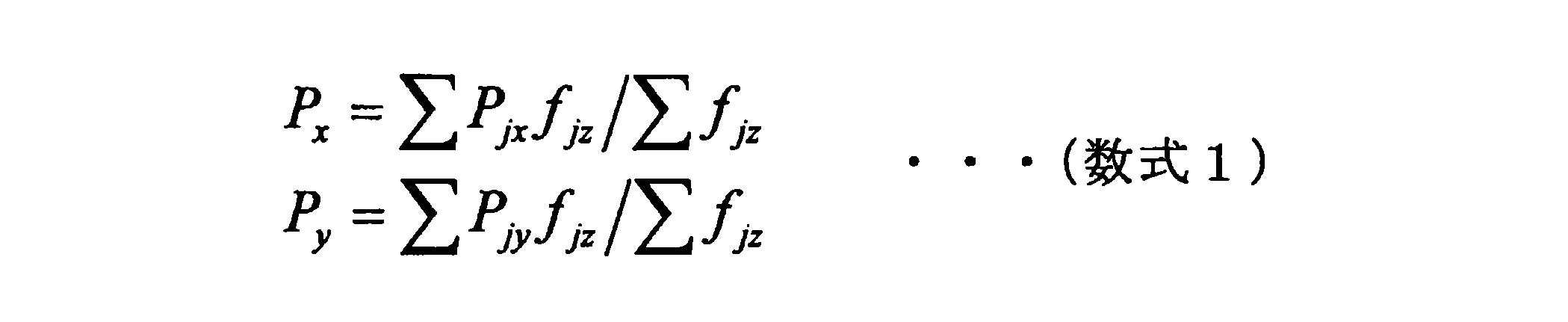
図3は、両足のZMPの算出方法を説明するための図である。図3に示すように、右足のZMPの位置ベクトルを(PRx,PRy)とし、当該位置において床面から受ける力のZ成分をfRzとする。また、左足のZMPの位置ベクトルを(PLx,PLy)とし、当該位置において床面から受ける力のZ成分をfLzとする。両足のZMPの位置ベクトル(Px,Py)は、次式により算出される。

<1.2.技術的課題>
スポーツの分野では、競技者が自身の体重移動を認識することが、上達の支援のために重要な場合がある。例えば、ゴルフのスウィング動作等の特定の動作における体重の移動に関し、動作と体重移動のタイミング、移動の量等を競技者が認識することで、上達がより早くなり得る。
スポーツの分野では、競技者が自身の体重移動を認識することが、上達の支援のために重要な場合がある。例えば、ゴルフのスウィング動作等の特定の動作における体重の移動に関し、動作と体重移動のタイミング、移動の量等を競技者が認識することで、上達がより早くなり得る。
このような体重移動を測定可能な機器の一例として、人が上に乗ることが可能な平板を備え、平板に乗った物体への床反力を測定するフォースプレートがある。しかし、フォースプレートは、平板という限られた範囲内の物体やその範囲内で行われる動作に測定対象が限定されたり、設置場所が室内に限られたり、水平に設置する必要がある等の制限が課せられる場合がある。
他の機器の一例として、インソール型の圧力分布センサがある。インソール型の圧力分布センサは、インソール上に圧力センサがひとつ以上配置され、センサを装着したユーザの足裏にかかる圧力の分布を測定可能である。インソール型の圧力分布センサは、上述した制限が課せられないため、フォースプレートよりも利便性が高いと言える。しかしながら、インソール型のセンサでの測定では、両足の配置関係(位置ベクトル)が未知であるため、上記数式2を用いて両足のZMPを算出することは困難であった。
そこで、上記事情を一着眼点にして、本開示の一実施形態に係るセンシングシステムを創作するに至った。本実施形態に係るセンシングシステムは、ユーザの姿勢を推定して、センサ情報からユーザの姿勢を加味した有用な情報を得ることが可能である。具体的には、本実施形態に係るセンシングシステムは、ユーザの両足の姿勢を推定して、両足のインソール型のセンサの各々から得られた圧力分布に基づいて、両足のZMPを算出することが可能である。
以上、本実施形態に係るセンシングシステムの概要を説明した。以下、図4~図11を参照して、本実施形態に係るセンシングシステムについて詳細に説明する。
<<2.構成例>>
図4は、本実施形態に係るセンシングシステム1の論理的な構成の一例を示すブロック図である。図4に示すように、本実施形態に係るセンシングシステム1は、情報処理装置100、センサ装置200及びカメラ300を含む。
図4は、本実施形態に係るセンシングシステム1の論理的な構成の一例を示すブロック図である。図4に示すように、本実施形態に係るセンシングシステム1は、情報処理装置100、センサ装置200及びカメラ300を含む。
センサ装置200は、対象物に関する情報を測定する機能を有する。例えば、センサ装置200は、ユーザの体のうち装着された部位の圧力分布を測定する圧力分布センサにより実現される。例えば、センサ装置200は、ユーザの両足の足裏に装着される上述したインソール型の圧力分布センサとして実現されてもよい。両足のZMPは、例えばゴルフのスウィング動作に関して有用である。インソール型の圧力分布センサを用いる場合、情報処理装置100は、ゴルフやスキーのように、シューズやスキー板等の道具を履く競技についても、両足のZMPを計算することが可能となる。また、センサ装置200は、ユーザの両手に装着されるグローブ型の圧力分布センサとして実現されてもよい。両手のZMPは、例えば体操選手の倒立動作に関して有用である。他にも、センサ装置200は、加速度センサ及びジャイロセンサ等の慣性センサ、筋電センサ、神経センサ、脈拍センサ及び体温センサ等の生体センサ、振動センサ又は地磁気センサ等により実現されてもよい。以下では、インソール型の圧力分布センサが用いられる例を想定して説明する。
カメラ300は、画像(静止画像/動画像)を撮像する機能を有する。カメラ300は、撮像レンズ、絞り、ズームレンズ、及びフォーカスレンズ等により構成されるレンズ系、レンズ系に対してフォーカス動作やズーム動作を行わせる駆動系、レンズ系で得られる撮像光を光電変換して撮像信号を生成する固体撮像素子アレイ等を有する。固体撮像素子アレイは、例えばCCD(Charge Coupled Device)センサアレイや、CMOS(Complementary Metal Oxide Semiconductor)センサアレイにより実現されてもよい。カメラ300は、デジタル信号とされた撮影画像のデータを情報処理装置100へ出力する。カメラ300と情報処理装置100との間では有線通信が行われてもよいし、無線通信が行われてもよい。
情報処理装置100は、複数のセンサ装置200から得られたセンサ情報から、ユーザの姿勢を加味した有用な情報を算出する。図4に示すように、情報処理装置100は、通信部110、記憶部120及び制御部130を含む。
通信部110は、外部機器との間でデータの送受信を行う通信モジュールである。例えば、通信部110は、センサ装置200及びカメラ300との間でデータの送受信を行う。通信部110は、例えば無線LAN(Local Area Network)、Wi-Fi(Wireless Fidelity、登録商標)、赤外線通信、Bluetooth(登録商標)等の方式で、センサ装置200及びカメラ300と直接的に、又はネットワークアクセスポイント等の他の通信ノードを経由して間接的に通信する。通信部110は、有線LAN等の方式で、外部機器と有線通信してもよい。
記憶部120は、所定の記録媒体に対してデータの記録再生を行う部位である。例えば、記憶部120は、複数のセンサ装置200から受信されたセンサ情報を記憶する。
制御部130は、演算処理装置および制御装置として機能し、各種プログラムに従って情報処理装置100内の動作全般を制御する。図4に示すように、制御部130は、取得部131、推定部133及び計算部135として機能する。
取得部131は、複数のセンサ装置200からセンサ情報を取得する機能を有する。推定部133は、センサ装置200が装着された複数の部位の配置を推定する機能を有する。計算部135は、取得部131により取得されたセンサ情報から推定部133による推定結果を加味した有用な情報を計算する機能を有する。
以上、本実施形態に係るセンシングシステム1の構成例を説明した。続いて、図5~図9を参照して、本実施形態に係るセンシングシステム1が有する機能を詳細に説明する。
<<3.機能詳細>>
<3.1.配置推定機能>
情報処理装置100(例えば、推定部133)は、センサ装置200の配置を推定する。本実施形態では、推定部133は、インソール型のセンサ装置200のように、互いに離隔し、且つ動的に配置関係が変化し得る複数のセンサ装置200の配置を推定する。
<3.1.配置推定機能>
情報処理装置100(例えば、推定部133)は、センサ装置200の配置を推定する。本実施形態では、推定部133は、インソール型のセンサ装置200のように、互いに離隔し、且つ動的に配置関係が変化し得る複数のセンサ装置200の配置を推定する。
具体的には、まず、推定部133は、センサ装置200が装着された複数の部位を含んだ撮像画像に基づいて当該複数の部位の配置を推定する。例えば、推定部133は、インソール型のセンサ装置200が装着された両足をカメラ300により撮像した撮像画像に基づいて、両足の配置を推定する。そして、推定部133は、複数の部位の配置の推定結果に基づいて、複数のセンサ装置200の配置を推定する。例えば、推定部133は、推定された右足と左足との成す角度や距離に、足とインソール型のセンサ装置200との相対的な配置関係を反映させることで、インソール上に設けられた圧力センサの各々の位置ベクトルを推定する。
ここで、撮像画像に基づく配置の推定方法は多様に考えられる。
例えば、推定部133は、撮像画像に含まれる複数の部位を画像認識することで、複数の部位の配置を推定してもよい。具体的には、推定部133は、靴の形状、模様及びサイズ等のデザイン情報を予め取得しておき、両足の靴が写された撮像画像を対象としてデザイン情報に基づいた画像認識を行うことで、両足の配置を推定してもよい。推定部133は、サーバ等からデザイン情報を取得してもよいし、靴に設けられたQRコード(登録商標)等の情報コードを画像認識することでデザイン情報を取得してもよい。
例えば、推定部133は、撮像画像に含まれる複数の部位に設けられたマーカーの各々の位置及び姿勢を推定することで、複数の部位の配置を推定してもよい。具体的には、推定部133は、両足の靴にそれぞれ設けられたAR(Augmented Reality)マーカーが写された撮像画像に基づいて、ARマーカーの位置及び姿勢を推定することで、両足の配置を推定してもよい。例えば、推定部133は、靴の形状、並びにARマーカーの形状、ARマーカーの取り付け位置及び取り付け角度等を示すデザイン情報を予め取得しておく。そして、推定部133は、ARマーカーの位置及び姿勢を推定し、デザイン情報を用いて推定結果から両足の配置を算出する。推定部133は、サーバ等からデザイン情報を取得してもよいし、靴に設けられたQRコード等の情報コードを画像認識することでデザイン情報を取得してもよい。また、推定部133は、靴のどの部分にARマーカーが設けられているかを示す情報を、サーバ等から取得してもよい。これにより、ARマーカーの認識のための負荷が軽減される。
ARマーカーの位置及び姿勢を推定するためのアルゴリズムとしては、例えば「加藤博一,Mark Billinghurst,浅野浩一,橘啓八郎:マーカー追跡に基づく拡張現実感システムとそのキャリブレーション,TVRSJ,Vol.4,No.4,1999」に開示されている。以下、図5~図9を参照して、アルゴリズムの一例を説明する。
(アルゴリズム例)
図5~図9は、本実施形態に係るARマーカーを用いた配置推定機能を説明するための図である。
図5~図9は、本実施形態に係るARマーカーを用いた配置推定機能を説明するための図である。
図5は、センシングシステム1の設定例を示している。図5に示した例では、情報処理装置100はスマートフォンであり、センサ装置200A及び200Bはインソール型の圧力分布センサであり、カメラ300はユーザの後ろからユーザの両足を撮像する。図5に示すように、ユーザが両足に履く靴の踵部分にARマーカー20A及び20Bが設けられており、カメラ300はARマーカー20A及び20Bを撮像することができる。なお、図5に示した例以外にも、例えば両足の甲を上から撮影するカメラが設けられ、両足の甲にARマーカーが設けられていてもよい。
図6は、カメラ300により撮像された撮像画像の一例を示している。図6に示すように、カメラ300により撮影された撮像画像には、ARマーカー20A及び20Bが含まれている。推定部133は、以下に説明するアルゴリズムを用いて、図6に一例を示した撮像画像から、ARマーカー20A及び20Bの位置及び姿勢をそれぞれ推定する。
本アルゴリズムでは、マーカー座標系(3D)、カメラ座標系(3D)、理想スクリーン座標系(2D)及び観測スクリーン座標系(2D)の4つの座標系を用いる。マーカー座標系は、仮想オブジェクトを表現する際に用いる座標系である。カメラ座標系は、焦点位置を原点、画像平面に垂直な方向をZ軸、画像のx軸及びy軸に平行な方向をそれぞれX軸及びY軸とした座標系である。なお、マーカー座標系で表現された点は、回転移動及び平行移動によりカメラ座標系に変換可能である。理想スクリーン座標系は、投影される画像平面の座標系である。観測スクリーン座標系は、実際のカメラ画像の座標系であり、理想スクリーン座標系から広角レンズのゆがみを考慮した座標系である。理想スクリーン座標系とカメラ座標系との間は、透視変換モデルを用いて変換可能である。理想スクリーン座標系とマーカー座標系とのの間も、透視変換モデルを用いて変換可能である。
本アルゴリズムでは、マーカー座標系(3D)からカメラ座標系(3D)への座標変換行列を求める。この座標変換行列は、回転移動成分と平行移動成分とから成る。
事前に、推定部133は、理想スクリーン座標系及びカメラ座標系の透視変換モデルのパラメータを、キャリブレーションにより求める。
カメラ画像が取得されると、推定部133は、カメラ画像(観測スクリーン座標系)から歪みを補正して、理想スクリーン座標系上のマーカーの頂点位置を求める。具体的には、推定部133は、マーカーを二値化(白黒画像化)し、マーカーの輪郭を検出して頂点位置を求める。
次いで、推定部133は、事前に算出しておいた透視変換モデルを用いて、理想スクリーン座標系上のマーカーの頂点位置をカメラ座標系に写像する。具体的には、図7に示すように、推定部133は、投影面31に写ったマーカーの4辺をカメラ300の投影方向に伸ばして面32を作る。そして、推定部133は、事前のカメラキャリブレーションによって得られたカメラの内部パラメータを用いて、これらの辺とカメラの光学中心を結んだ4つの面33を作る。
そして、推定部133は、向かい合った面の交線ベクトルを求める。具体的には、推定部133は、図8に示すように、向かい合った面33A及び33Bの交線ベクトル34Aを求める。また、推定部133は、図9に示すように、向かい合った面33C及び33Dの交線ベクトル34Bを求める。さらに、推定部133は、2つの交線ベクトルから外積を計算する。これにより、マーカーの回転移動成分が求まる。
次に、推定部133は、マーカーの4つの頂点の、画像座標系における位置とマーカーの大きさとからマーカー座標系のおける位置を求める。そして、推定部133は、マーカー座標系におけるマーカーの位置、回転移動成分の情報、及びキャリブレーションの情報から、マーカーの平行移動成分の情報を求める。
以上説明した処理により、推定部133は、キャリブレーション情報、マーカーの回転移動成分及び平行移動成分の情報を求める。推定部133は、これらの情報を用いることで、理想スクリーン座標系上のマーカーの位置情報から、カメラ座標系でのマーカーの位置及び姿勢を求めることができる。
<3.2.更新機能>
情報処理装置100(例えば、推定部133)は、センサ装置200が装着された複数の部位の配置を、逐次的に推定して推定結果を更新してもよい。例えば、推定部133は、複数の部位の動作に応じて繰り返し配置を推定してもよい。例えば、走るユーザと並走してカメラ300が移動する機構により継続的に撮像されたユーザの画像から、推定部133は、走るユーザの両足の配置を繰り返し推定する。
情報処理装置100(例えば、推定部133)は、センサ装置200が装着された複数の部位の配置を、逐次的に推定して推定結果を更新してもよい。例えば、推定部133は、複数の部位の動作に応じて繰り返し配置を推定してもよい。例えば、走るユーザと並走してカメラ300が移動する機構により継続的に撮像されたユーザの画像から、推定部133は、走るユーザの両足の配置を繰り返し推定する。
これにより、センシングシステム1は、動くユーザの両足の配置をリアルタイムに取得することが可能である。例えば、センシングシステム1は、フォースプレートの平板よりも広い範囲を動き回るユーザについても、両足のZMPを継続的に算出することができる。また、センシングシステム1は、走るユーザの着地した両足の幅から歩幅等の情報を算出することができる。
<3.3.情報取得機能>
(情報取得機能)
情報処理装置100(例えば、取得部131)は、複数のセンサ装置200からセンサ情報を取得する。
(情報取得機能)
情報処理装置100(例えば、取得部131)は、複数のセンサ装置200からセンサ情報を取得する。
例えば、取得部131は、センサ装置200から送信されたセンサ情報を取得してもよい。例えば、センサ装置200は、通信用インタフェースを有し、センサ情報を情報処理装置100へ無線通信又は有線通信を用いて送信する。そして、情報処理装置100は、センサ装置200から送信されたセンサ情報を、通信部110を経由して取得する。
例えば、取得部131は、撮像画像に含まれる複数の部位に設けられた表示装置に表示された表示内容からセンサ情報を取得してもよい。例えば、靴の踵や甲等にセンサ情報を表す情報コードを表示する電子ペーパー等の表示装置が形成され、インソール型のセンサ装置200がセンサ情報を表示装置に表示させる。そして、取得部131は、この表示装置が撮像された撮像画像を画像認識することで、情報コードに表されたセンサ情報を取得する。この場合、センサ装置200は、通信用インタフェースを有さなくてもよく、且つ情報処理装置100は、通信部110を有さなくてもよい。
<3.4.ZMP計算機能>
情報処理装置100(例えば、計算部135)は、推定部133により推定された複数の部位の配置に基づいて、取得部131により取得されたセンサ情報から複数の部位に関する情報を計算する。例えば、計算部135は、センサ装置200の配置に基づいて、複数のセンサ情報から、センサ装置200が装着された複数の部位の全体における情報を計算する。このような情報としては、例えばZMPが挙げられる。インソール型のセンサ装置200に関しては、計算部135は、推定部133により推定されたインソール上に配置された圧力センサの位置ベクトル、及び取得部131により取得されたセンサ情報を上記数式1及び2に代入することで、両足のZMPを計算する。
情報処理装置100(例えば、計算部135)は、推定部133により推定された複数の部位の配置に基づいて、取得部131により取得されたセンサ情報から複数の部位に関する情報を計算する。例えば、計算部135は、センサ装置200の配置に基づいて、複数のセンサ情報から、センサ装置200が装着された複数の部位の全体における情報を計算する。このような情報としては、例えばZMPが挙げられる。インソール型のセンサ装置200に関しては、計算部135は、推定部133により推定されたインソール上に配置された圧力センサの位置ベクトル、及び取得部131により取得されたセンサ情報を上記数式1及び2に代入することで、両足のZMPを計算する。
以上、本実施形態に係るセンシングシステム1が有する機能を詳細に説明した。続いて、図10を参照して、本実施形態に係るセンシングシステム1の動作処理例を説明する。
<<4.動作処理例>>
図10は、本実施形態に係るセンシングシステム1において実行される両足のZMPの計算処理の流れの一例を示すフローチャートである。
図10は、本実施形態に係るセンシングシステム1において実行される両足のZMPの計算処理の流れの一例を示すフローチャートである。
まず、ステップS102で、センシングシステム1は、初期化処理を行う。例えば、センシングシステム1は、情報処理装置100がカメラ300から撮像画像を取得するための設定や、カメラ300の内部パラメータの設定、ARマーカーのロード、及びカメラ300による撮像の開始処理等を行う。
次いで、ステップS104で、センシングシステム1は、センサ情報を取得する。例えば、情報処理装置100は、ユーザの両足に装着されたインソール型のセンサ装置200から、圧力分布を受信する。
次に、ステップS106で、センシングシステム1は、撮像画像を取得する。例えば、ユーザの後ろに設けられたカメラ300が、ユーザが両足に履く靴の踵部分に設けられたARマーカーを含む撮像画像を撮像して、情報処理装置100へ送信する。
次いで、ステップS108で、センシングシステム1は、ARマーカーの位置及び姿勢を推定する。例えば、情報処理装置100は、上述したアルゴリズムを用いて、両足の踵部分に設けられたARマーカーの位置及び姿勢を推定する。
次に、ステップS110で、センシングシステム1は、センサ装置200の配置を推定する。例えば、情報処理装置100は、ARマーカーの位置及び姿勢に基づいて、インソール上に設けられた圧力センサの各々の位置ベクトルを推定する。
そして、ステップS112で、センシングシステム1は、両足のZMPを計算する。例えば、情報処理装置100は、推定した圧力センサの位置ベクトル及び取得したセンサ情報を上記数式1及び2に代入することで、両足のZMPを計算する。
終了されるまでの間(ステップS114/NO)、上記ステップS104~S112が繰り返される。終了される場合(ステップS114/YES)、ステップS116で、センシングシステム1は、終了処理を行う。例えば、センシングシステム1は、カメラ300の撮影終了処理やクリーンアップ処理等を行う。
<<5.ハードウェア構成例>>
最後に、図11を参照して、本実施形態に係る情報処理装置のハードウェア構成について説明する。図11は、本実施形態に係る情報処理装置のハードウェア構成の一例を示すブロック図である。なお、図11に示す情報処理装置900は、例えば、図4に示した情報処理装置100を実現し得る。本実施形態に係る情報処理装置100による情報処理は、ソフトウェアと、以下に説明するハードウェアとの協働により実現される。
最後に、図11を参照して、本実施形態に係る情報処理装置のハードウェア構成について説明する。図11は、本実施形態に係る情報処理装置のハードウェア構成の一例を示すブロック図である。なお、図11に示す情報処理装置900は、例えば、図4に示した情報処理装置100を実現し得る。本実施形態に係る情報処理装置100による情報処理は、ソフトウェアと、以下に説明するハードウェアとの協働により実現される。
図11に示すように、情報処理装置900は、CPU(Central Processing Unit)901、ROM(Read Only Memory)902、RAM(Random Access Memory)903及びホストバス904aを備える。また、情報処理装置900は、ブリッジ904、外部バス904b、インタフェース905、入力装置906、出力装置907、ストレージ装置908、ドライブ909、接続ポート911及び通信装置913を備える。情報処理装置900は、CPU901に代えて、又はこれとともに、DSP若しくはASIC等の処理回路を有してもよい。
CPU901は、演算処理装置および制御装置として機能し、各種プログラムに従って情報処理装置900内の動作全般を制御する。また、CPU901は、マイクロプロセッサであってもよい。ROM902は、CPU901が使用するプログラムや演算パラメータ等を記憶する。RAM903は、CPU901の実行において使用するプログラムや、その実行において適宜変化するパラメータ等を一時記憶する。CPU901は、例えば、図4に示す制御部130を形成し得る。
CPU901、ROM902及びRAM903は、CPUバスなどを含むホストバス904aにより相互に接続されている。ホストバス904aは、ブリッジ904を介して、PCI(Peripheral Component Interconnect/Interface)バスなどの外部バス904bに接続されている。なお、必ずしもホストバス904a、ブリッジ904および外部バス904bを分離構成する必要はなく、1つのバスにこれらの機能を実装してもよい。
入力装置906は、例えば、マウス、キーボード、タッチパネル、ボタン、マイクロフォン、スイッチ及びレバー等、ユーザによって情報が入力される装置によって実現される。また、入力装置906は、例えば、赤外線やその他の電波を利用したリモートコントロール装置であってもよいし、情報処理装置900の操作に対応した携帯電話やPDA等の外部接続機器であってもよい。さらに、入力装置906は、例えば、上記の入力手段を用いてユーザにより入力された情報に基づいて入力信号を生成し、CPU901に出力する入力制御回路などを含んでいてもよい。情報処理装置900のユーザは、この入力装置906を操作することにより、情報処理装置900に対して各種のデータを入力したり処理動作を指示したりすることができる。
出力装置907は、取得した情報をユーザに対して視覚的又は聴覚的に通知することが可能な装置で形成される。このような装置として、CRTディスプレイ装置、液晶ディスプレイ装置、プラズマディスプレイ装置、ELディスプレイ装置及びランプ等の表示装置や、スピーカ及びヘッドホン等の音声出力装置や、プリンタ装置等がある。出力装置907は、例えば、情報処理装置900が行った各種処理により得られた結果を出力する。具体的には、表示装置は、情報処理装置900が行った各種処理により得られた結果を、テキスト、イメージ、表、グラフ等、様々な形式で視覚的に表示する。他方、音声出力装置は、再生された音声データや音響データ等からなるオーディオ信号をアナログ信号に変換して聴覚的に出力する。
ストレージ装置908は、情報処理装置900の記憶部の一例として形成されたデータ格納用の装置である。ストレージ装置908は、例えば、HDD等の磁気記憶部デバイス、半導体記憶デバイス、光記憶デバイス又は光磁気記憶デバイス等により実現される。ストレージ装置908は、記憶媒体、記憶媒体にデータを記録する記録装置、記憶媒体からデータを読み出す読出し装置および記憶媒体に記録されたデータを削除する削除装置などを含んでもよい。このストレージ装置908は、CPU901が実行するプログラムや各種データ及び外部から取得した各種のデータ等を格納する。ストレージ装置908は、例えば、図4に示す記憶部120を形成し得る。
ドライブ909は、記憶媒体用リーダライタであり、情報処理装置900に内蔵、あるいは外付けされる。ドライブ909は、装着されている磁気ディスク、光ディスク、光磁気ディスク、または半導体メモリ等のリムーバブル記憶媒体に記録されている情報を読み出して、RAM903に出力する。また、ドライブ909は、リムーバブル記憶媒体に情報を書き込むこともできる。
接続ポート911は、外部機器と接続されるインタフェースであって、例えばUSB(Universal Serial Bus)などによりデータ伝送可能な外部機器との接続口である。本実施形態では、接続ポート911は、例えば、図4に示すカメラ300が接続され得る。
通信装置913は、例えば、ネットワーク920に接続するための通信デバイス等で形成された通信インタフェースである。通信装置913は、例えば、有線若しくは無線LAN(Local Area Network)、LTE(Long Term Evolution)、Bluetooth(登録商標)又はWUSB(Wireless USB)用の通信カード等である。また、通信装置913は、光通信用のルータ、ADSL(Asymmetric Digital Subscriber Line)用のルータ又は各種通信用のモデム等であってもよい。この通信装置913は、例えば、インターネットや他の通信機器との間で、例えばTCP/IP等の所定のプロトコルに則して信号等を送受信することができる。通信装置913は、例えば、図4に示す通信部110を形成し得る。
なお、ネットワーク920は、ネットワーク920に接続されている装置から送信される情報の有線、または無線の伝送路である。例えば、ネットワーク920は、インターネット、電話回線網、衛星通信網などの公衆回線網や、Ethernet(登録商標)を含む各種のLAN(Local Area Network)、WAN(Wide Area Network)などを含んでもよい。また、ネットワーク920は、IP-VPN(Internet Protocol-Virtual Private Network)などの専用回線網を含んでもよい。
以上、本実施形態に係る情報処理装置900の機能を実現可能なハードウェア構成の一例を示した。上記の各構成要素は、汎用的な部材を用いて実現されていてもよいし、各構成要素の機能に特化したハードウェアにより実現されていてもよい。従って、本実施形態を実施する時々の技術レベルに応じて、適宜、利用するハードウェア構成を変更することが可能である。
なお、上述のような本実施形態に係る情報処理装置900の各機能を実現するためのコンピュータプログラムを作製し、PC等に実装することが可能である。また、このようなコンピュータプログラムが格納された、コンピュータで読み取り可能な記録媒体も提供することができる。記録媒体は、例えば、磁気ディスク、光ディスク、光磁気ディスク、フラッシュメモリ等である。また、上記のコンピュータプログラムは、記録媒体を用いずに、例えばネットワークを介して配信されてもよい。
<<6.まとめ>>
以上、図1~図11を参照して、本開示の一実施形態について詳細に説明した。上記説明したように、情報処理装置100は、ユーザの体のうち装着された部位の圧力分布を測定する複数のセンサ装置200からセンサ情報を取得し、センサ装置200が装着された複数の部位を含んだ撮像画像に基づいて当該複数の部位の配置を推定する。そして、情報処理装置100は、推定された複数の部位の配置に基づいて、取得されたセンサ情報から複数の部位に関する情報を計算する。これにより、情報処理装置100は、センサ情報から対象者の姿勢を加味した、例えば両足のZMP等の有用な情報を得ることが可能である。
以上、図1~図11を参照して、本開示の一実施形態について詳細に説明した。上記説明したように、情報処理装置100は、ユーザの体のうち装着された部位の圧力分布を測定する複数のセンサ装置200からセンサ情報を取得し、センサ装置200が装着された複数の部位を含んだ撮像画像に基づいて当該複数の部位の配置を推定する。そして、情報処理装置100は、推定された複数の部位の配置に基づいて、取得されたセンサ情報から複数の部位に関する情報を計算する。これにより、情報処理装置100は、センサ情報から対象者の姿勢を加味した、例えば両足のZMP等の有用な情報を得ることが可能である。
例えば、センサ装置200は、インソール型であってもよい。この場合、情報処理装置100は、フォースプレートを用いなくても、両足のZMPを計算することができる。また、ゴルフのスイング動作のように、地面から足が離れるような動作に関しては、情報処理装置100は、両足の姿勢などの圧力分布以外の情報を得ることができる。
以上、添付図面を参照しながら本開示の好適な実施形態について詳細に説明したが、本開示の技術的範囲はかかる例に限定されない。本開示の技術分野における通常の知識を有する者であれば、請求の範囲に記載された技術的思想の範疇内において、各種の変更例または修正例に想到し得ることは明らかであり、これらについても、当然に本開示の技術的範囲に属するものと了解される。
例えば、上記実施形態では、情報処理装置100はスマートフォンとして実現される例を説明したが、本技術はかかる例に限定されない。例えば、情報処理装置100は、タブレット端末、PC又はネットワーク上のサーバ等の任意の装置として実現されてもよい。
また、情報処理装置100は、単独の装置として実現されてもよく、一部または全部が別々の装置として実現されても良い。例えば、図4に示した情報処理装置100の機能構成例のうち、記憶部120及び制御部130が、通信部110とネットワーク等で接続されたサーバ等の装置に備えられていても良い。また、情報処理装置100は、センサ装置200又はカメラ300と一体的に形成されてもよい。
また、本明細書に記載された効果は、あくまで説明的または例示的なものであって限定的ではない。つまり、本開示に係る技術は、上記の効果とともに、または上記の効果に代えて、本明細書の記載から当業者には明らかな他の効果を奏しうる。
なお、以下のような構成も本開示の技術的範囲に属する。
(1)
ユーザの体のうち装着された部位の圧力分布を測定する複数のセンサ装置から測定結果を示す情報を取得する取得部と、
前記センサ装置が装着された複数の部位を含んだ撮像画像に基づいて前記複数の部位の配置を推定する推定部と、
前記推定部により推定された前記複数の部位の配置に基づいて、前記取得部により取得された前記測定結果を示す情報から前記複数の部位に関する情報を計算する計算部と、
を備える情報処理装置。
(2)
前記推定部は、前記複数の部位の配置の推定結果に基づいて、前記複数のセンサ装置の配置を推定する、前記(1)に記載の情報処理装置。
(3)
前記計算部は、前記複数の部位の全体におけるZMP(zero moment point)を計算する、前記(1)又は(2)に記載の情報処理装置。
(4)
前記複数の部位は、前記ユーザの両足である、前記(1)~(3)のいずれか一項に記載の情報処理装置。
(5)
前記センサ装置は、インソール型である、前記(4)に記載の情報処理装置。
(6)
前記複数の部位は、前記ユーザの両手である、前記(1)~(3)のいずれか一項に記載の情報処理装置。
(7)
前記推定部は、前記撮像画像に含まれる前記複数の部位に設けられたマーカーの各々の位置及び姿勢を推定することで、前記複数の部位の配置を推定する、前記(1)~(6)のいずれか一項に記載の情報処理装置。
(8)
前記推定部は、前記撮像画像に含まれる前記複数の部位を画像認識することで、前記複数の部位の配置を推定する、前記(1)~(7)のいずれか一項に記載の情報処理装置。
(9)
前記推定部は、前記複数の部位の動作に応じて繰り返し推定する、前記(1)~(8)のいずれか一項に記載の情報処理装置。
(10)
前記取得部は、前記センサ装置から送信された前記測定結果を示す情報を取得する、前記(1)~(9)のいずれか一項に記載の情報処理装置。
(11)
前記取得部は、前記撮像画像に含まれる前記複数の部位に設けられた表示装置に表示された表示内容から前記測定結果を示す情報を取得する、前記(1)~(9)のいずれか一項に記載の情報処理装置。
(12)
ユーザの体のうち装着された部位の圧力分布を測定する複数のセンサ装置から測定結果を示す情報を取得することと、
前記センサ装置が装着された複数の部位を含んだ撮像画像に基づいて前記複数の部位の配置を推定することと、
推定された前記複数の部位の配置に基づいて、取得された前記測定結果を示す情報から前記複数の部位に関する情報を計算することと、
を含むプロセッサにより実行される情報処理方法。
(1)
ユーザの体のうち装着された部位の圧力分布を測定する複数のセンサ装置から測定結果を示す情報を取得する取得部と、
前記センサ装置が装着された複数の部位を含んだ撮像画像に基づいて前記複数の部位の配置を推定する推定部と、
前記推定部により推定された前記複数の部位の配置に基づいて、前記取得部により取得された前記測定結果を示す情報から前記複数の部位に関する情報を計算する計算部と、
を備える情報処理装置。
(2)
前記推定部は、前記複数の部位の配置の推定結果に基づいて、前記複数のセンサ装置の配置を推定する、前記(1)に記載の情報処理装置。
(3)
前記計算部は、前記複数の部位の全体におけるZMP(zero moment point)を計算する、前記(1)又は(2)に記載の情報処理装置。
(4)
前記複数の部位は、前記ユーザの両足である、前記(1)~(3)のいずれか一項に記載の情報処理装置。
(5)
前記センサ装置は、インソール型である、前記(4)に記載の情報処理装置。
(6)
前記複数の部位は、前記ユーザの両手である、前記(1)~(3)のいずれか一項に記載の情報処理装置。
(7)
前記推定部は、前記撮像画像に含まれる前記複数の部位に設けられたマーカーの各々の位置及び姿勢を推定することで、前記複数の部位の配置を推定する、前記(1)~(6)のいずれか一項に記載の情報処理装置。
(8)
前記推定部は、前記撮像画像に含まれる前記複数の部位を画像認識することで、前記複数の部位の配置を推定する、前記(1)~(7)のいずれか一項に記載の情報処理装置。
(9)
前記推定部は、前記複数の部位の動作に応じて繰り返し推定する、前記(1)~(8)のいずれか一項に記載の情報処理装置。
(10)
前記取得部は、前記センサ装置から送信された前記測定結果を示す情報を取得する、前記(1)~(9)のいずれか一項に記載の情報処理装置。
(11)
前記取得部は、前記撮像画像に含まれる前記複数の部位に設けられた表示装置に表示された表示内容から前記測定結果を示す情報を取得する、前記(1)~(9)のいずれか一項に記載の情報処理装置。
(12)
ユーザの体のうち装着された部位の圧力分布を測定する複数のセンサ装置から測定結果を示す情報を取得することと、
前記センサ装置が装着された複数の部位を含んだ撮像画像に基づいて前記複数の部位の配置を推定することと、
推定された前記複数の部位の配置に基づいて、取得された前記測定結果を示す情報から前記複数の部位に関する情報を計算することと、
を含むプロセッサにより実行される情報処理方法。
1 センシングシステム
100 情報処理装置
110 通信部
120 記憶部
130 制御部
131 取得部
133 推定部
135 計算部
200 センサ装置
300 カメラ
100 情報処理装置
110 通信部
120 記憶部
130 制御部
131 取得部
133 推定部
135 計算部
200 センサ装置
300 カメラ
Claims (12)
- ユーザの体のうち装着された部位の圧力分布を測定する複数のセンサ装置から測定結果を示す情報を取得する取得部と、
前記センサ装置が装着された複数の部位を含んだ撮像画像に基づいて前記複数の部位の配置を推定する推定部と、
前記推定部により推定された前記複数の部位の配置に基づいて、前記取得部により取得された前記測定結果を示す情報から前記複数の部位に関する情報を計算する計算部と、
を備える情報処理装置。 - 前記推定部は、前記複数の部位の配置の推定結果に基づいて、前記複数のセンサ装置の配置を推定する、請求項1に記載の情報処理装置。
- 前記計算部は、前記複数の部位の全体におけるZMP(zero moment point)を計算する、請求項1に記載の情報処理装置。
- 前記複数の部位は、前記ユーザの両足である、請求項1に記載の情報処理装置。
- 前記センサ装置は、インソール型である、請求項4に記載の情報処理装置。
- 前記複数の部位は、前記ユーザの両手である、請求項1に記載の情報処理装置。
- 前記推定部は、前記撮像画像に含まれる前記複数の部位に設けられたマーカーの各々の位置及び姿勢を推定することで、前記複数の部位の配置を推定する、請求項1に記載の情報処理装置。
- 前記推定部は、前記撮像画像に含まれる前記複数の部位を画像認識することで、前記複数の部位の配置を推定する、請求項1に記載の情報処理装置。
- 前記推定部は、前記複数の部位の動作に応じて繰り返し推定する、請求項1に記載の情報処理装置。
- 前記取得部は、前記センサ装置から送信された前記測定結果を示す情報を取得する、請求項1に記載の情報処理装置。
- 前記取得部は、前記撮像画像に含まれる前記複数の部位に設けられた表示装置に表示された表示内容から前記測定結果を示す情報を取得する、請求項1に記載の情報処理装置。
- ユーザの体のうち装着された部位の圧力分布を測定する複数のセンサ装置から測定結果を示す情報を取得することと、
前記センサ装置が装着された複数の部位を含んだ撮像画像に基づいて前記複数の部位の配置を推定することと、
推定された前記複数の部位の配置に基づいて、取得された前記測定結果を示す情報から前記複数の部位に関する情報を計算することと、
を含むプロセッサにより実行される情報処理方法。
Priority Applications (3)
| Application Number | Priority Date | Filing Date | Title |
|---|---|---|---|
| JP2017504901A JPWO2016143402A1 (ja) | 2015-03-11 | 2016-01-27 | 情報処理装置及び情報処理方法 |
| EP16761374.4A EP3269302A4 (en) | 2015-03-11 | 2016-01-27 | Information processing apparatus and information processing method |
| US15/551,434 US20180028861A1 (en) | 2015-03-11 | 2016-01-27 | Information processing device and information processing method |
Applications Claiming Priority (2)
| Application Number | Priority Date | Filing Date | Title |
|---|---|---|---|
| JP2015048172 | 2015-03-11 | ||
| JP2015-048172 | 2015-03-11 |
Publications (1)
| Publication Number | Publication Date |
|---|---|
| WO2016143402A1 true WO2016143402A1 (ja) | 2016-09-15 |
Family
ID=56880216
Family Applications (1)
| Application Number | Title | Priority Date | Filing Date |
|---|---|---|---|
| PCT/JP2016/052296 Ceased WO2016143402A1 (ja) | 2015-03-11 | 2016-01-27 | 情報処理装置及び情報処理方法 |
Country Status (4)
| Country | Link |
|---|---|
| US (1) | US20180028861A1 (ja) |
| EP (1) | EP3269302A4 (ja) |
| JP (1) | JPWO2016143402A1 (ja) |
| WO (1) | WO2016143402A1 (ja) |
Cited By (1)
| Publication number | Priority date | Publication date | Assignee | Title |
|---|---|---|---|---|
| US11941480B2 (en) | 2019-10-31 | 2024-03-26 | Nec Corporation | Information processing system, information processing device, insole, information processing method, and recording medium |
Families Citing this family (5)
| Publication number | Priority date | Publication date | Assignee | Title |
|---|---|---|---|---|
| US11047706B2 (en) * | 2016-02-01 | 2021-06-29 | One Two Free Inc. | Pedometer with accelerometer and foot motion distinguishing method |
| CN110227244A (zh) * | 2019-06-21 | 2019-09-13 | 上海电机学院 | 肌肉电控制的模拟拳击互动系统 |
| CN111015653B (zh) * | 2019-12-13 | 2021-06-04 | 深圳市优必选科技股份有限公司 | 机器人控制方法、装置、计算机可读存储介质及机器人 |
| CN112975941B (zh) * | 2019-12-13 | 2022-06-24 | 深圳市优必选科技股份有限公司 | 机器人控制方法、装置、计算机可读存储介质及机器人 |
| CN111966213B (zh) * | 2020-06-29 | 2024-11-26 | 青岛小鸟看看科技有限公司 | 图像处理方法、装置、设备及存储介质 |
Citations (3)
| Publication number | Priority date | Publication date | Assignee | Title |
|---|---|---|---|---|
| JP2008048981A (ja) * | 2006-08-25 | 2008-03-06 | Kochi Univ Of Technology | 立ち上がり訓練機 |
| JP2009285269A (ja) * | 2008-05-30 | 2009-12-10 | Hirofumi Shinozaki | 人体構造の異常状態の物理的な観測と解析方法及び、同方法を用いた測定装置 |
| JP2013192721A (ja) * | 2012-03-19 | 2013-09-30 | Terumo Corp | 足圧分布計測システム及び情報処理装置 |
Family Cites Families (4)
| Publication number | Priority date | Publication date | Assignee | Title |
|---|---|---|---|---|
| JP4581087B2 (ja) * | 2005-01-31 | 2010-11-17 | 国立大学法人九州工業大学 | 歩行訓練支援装置 |
| JP2006280762A (ja) * | 2005-04-04 | 2006-10-19 | Anet Corporation | ライフコンディションレコーダー装置および身体情報処理システム |
| US8253586B1 (en) * | 2009-04-24 | 2012-08-28 | Mayfonk Art, Inc. | Athletic-wear having integral measuring sensors |
| JP2015026286A (ja) * | 2013-07-26 | 2015-02-05 | セイコーエプソン株式会社 | 表示装置、表示システムおよび表示装置の制御方法 |
-
2016
- 2016-01-27 US US15/551,434 patent/US20180028861A1/en not_active Abandoned
- 2016-01-27 EP EP16761374.4A patent/EP3269302A4/en not_active Ceased
- 2016-01-27 JP JP2017504901A patent/JPWO2016143402A1/ja active Pending
- 2016-01-27 WO PCT/JP2016/052296 patent/WO2016143402A1/ja not_active Ceased
Patent Citations (3)
| Publication number | Priority date | Publication date | Assignee | Title |
|---|---|---|---|---|
| JP2008048981A (ja) * | 2006-08-25 | 2008-03-06 | Kochi Univ Of Technology | 立ち上がり訓練機 |
| JP2009285269A (ja) * | 2008-05-30 | 2009-12-10 | Hirofumi Shinozaki | 人体構造の異常状態の物理的な観測と解析方法及び、同方法を用いた測定装置 |
| JP2013192721A (ja) * | 2012-03-19 | 2013-09-30 | Terumo Corp | 足圧分布計測システム及び情報処理装置 |
Non-Patent Citations (1)
| Title |
|---|
| See also references of EP3269302A4 * |
Cited By (1)
| Publication number | Priority date | Publication date | Assignee | Title |
|---|---|---|---|---|
| US11941480B2 (en) | 2019-10-31 | 2024-03-26 | Nec Corporation | Information processing system, information processing device, insole, information processing method, and recording medium |
Also Published As
| Publication number | Publication date |
|---|---|
| JPWO2016143402A1 (ja) | 2017-12-21 |
| EP3269302A1 (en) | 2018-01-17 |
| EP3269302A4 (en) | 2018-08-01 |
| US20180028861A1 (en) | 2018-02-01 |
Similar Documents
| Publication | Publication Date | Title |
|---|---|---|
| JP7396438B2 (ja) | プログラム、情報処理装置、及び情報処理方法 | |
| JP7574525B2 (ja) | 高さ測定方法および装置、ならびに端末 | |
| JPWO2016143402A1 (ja) | 情報処理装置及び情報処理方法 | |
| EP2359606B1 (en) | Tracking system calibration with minimal user input | |
| EP2359223B1 (en) | Correcting angle error in a tracking system | |
| JP4136859B2 (ja) | 位置姿勢計測方法 | |
| CN111353355B (zh) | 动作追踪系统及方法 | |
| KR101118654B1 (ko) | 모션캡쳐 기반의 자세분석을 통한 재활 장치 및 이에 따른 재활 방법 | |
| JP6933110B2 (ja) | カメラの外部パラメータの推定方法、推定装置および推定プログラム | |
| JP2011524048A (ja) | 画像解析および超音波通信を使用したコントローラの三次元位置の決定 | |
| KR101896827B1 (ko) | 사용자 자세 추정 장치 및 방법 | |
| WO2021243572A1 (zh) | 运动检测方法和装置、电子设备以及计算机可读存储介质 | |
| KR102097033B1 (ko) | 보디 포인트 인터액션 센싱을 통한 모션 추정 시스템 | |
| CN209221474U (zh) | 一种vr系统 | |
| CN112712545B (zh) | 人体部分跟踪方法和人体部分跟踪系统 | |
| CN114005175A (zh) | 一种吊环运动评分装置、方法、系统及计算机存储介质 | |
| CN111443812A (zh) | 基于vr的自由活动方法、vr装置、设备及存储介质 | |
| US11783492B2 (en) | Human body portion tracking method and human body portion tracking system | |
| WO2016208290A1 (ja) | 測定装置及び測定方法 | |
| JP6482102B2 (ja) | 測定装置及び測定方法 | |
| EP4625312A1 (en) | Information processing device and information processing method | |
| Ku et al. | Simulating Feasibility Assessment of the Golf Swing by Kinect Motion-Sensing Photography. | |
| JP2018005474A (ja) | 移動体識別装置、移動体識別システム、移動体識別方法及びプログラム | |
| KR20100060622A (ko) | 인체 자세 판별 시스템 및 그 방법 | |
| CN111435535A (zh) | 一种关节点信息的获取方法及装置 |
Legal Events
| Date | Code | Title | Description |
|---|---|---|---|
| 121 | Ep: the epo has been informed by wipo that ep was designated in this application |
Ref document number: 16761374 Country of ref document: EP Kind code of ref document: A1 |
|
| ENP | Entry into the national phase |
Ref document number: 2017504901 Country of ref document: JP Kind code of ref document: A |
|
| REEP | Request for entry into the european phase |
Ref document number: 2016761374 Country of ref document: EP |
|
| NENP | Non-entry into the national phase |
Ref country code: DE |