WO2016143848A1 - 真水生成装置 - Google Patents
真水生成装置 Download PDFInfo
- Publication number
- WO2016143848A1 WO2016143848A1 PCT/JP2016/057553 JP2016057553W WO2016143848A1 WO 2016143848 A1 WO2016143848 A1 WO 2016143848A1 JP 2016057553 W JP2016057553 W JP 2016057553W WO 2016143848 A1 WO2016143848 A1 WO 2016143848A1
- Authority
- WO
- WIPO (PCT)
- Prior art keywords
- water
- storage tank
- air
- fresh water
- absorbing
- Prior art date
- Legal status (The legal status is an assumption and is not a legal conclusion. Google has not performed a legal analysis and makes no representation as to the accuracy of the status listed.)
- Ceased
Links
Images

Classifications
-
- B—PERFORMING OPERATIONS; TRANSPORTING
- B01—PHYSICAL OR CHEMICAL PROCESSES OR APPARATUS IN GENERAL
- B01D—SEPARATION
- B01D1/00—Evaporating
-
- B—PERFORMING OPERATIONS; TRANSPORTING
- B01—PHYSICAL OR CHEMICAL PROCESSES OR APPARATUS IN GENERAL
- B01D—SEPARATION
- B01D1/00—Evaporating
- B01D1/14—Evaporating with heated gases or vapours or liquids in contact with the liquid
-
- B—PERFORMING OPERATIONS; TRANSPORTING
- B01—PHYSICAL OR CHEMICAL PROCESSES OR APPARATUS IN GENERAL
- B01D—SEPARATION
- B01D1/00—Evaporating
- B01D1/30—Accessories for evaporators ; Constructional details thereof
-
- B—PERFORMING OPERATIONS; TRANSPORTING
- B01—PHYSICAL OR CHEMICAL PROCESSES OR APPARATUS IN GENERAL
- B01D—SEPARATION
- B01D15/00—Separating processes involving the treatment of liquids with solid sorbents; Apparatus therefor
-
- B—PERFORMING OPERATIONS; TRANSPORTING
- B01—PHYSICAL OR CHEMICAL PROCESSES OR APPARATUS IN GENERAL
- B01D—SEPARATION
- B01D5/00—Condensation of vapours; Recovering volatile solvents by condensation
- B01D5/0027—Condensation of vapours; Recovering volatile solvents by condensation by direct contact between vapours or gases and the cooling medium
-
- B—PERFORMING OPERATIONS; TRANSPORTING
- B01—PHYSICAL OR CHEMICAL PROCESSES OR APPARATUS IN GENERAL
- B01D—SEPARATION
- B01D5/00—Condensation of vapours; Recovering volatile solvents by condensation
- B01D5/0033—Other features
- B01D5/0039—Recuperation of heat, e.g. use of heat pump(s), compression
-
- B—PERFORMING OPERATIONS; TRANSPORTING
- B01—PHYSICAL OR CHEMICAL PROCESSES OR APPARATUS IN GENERAL
- B01D—SEPARATION
- B01D5/00—Condensation of vapours; Recovering volatile solvents by condensation
- B01D5/0057—Condensation of vapours; Recovering volatile solvents by condensation in combination with other processes
- B01D5/006—Condensation of vapours; Recovering volatile solvents by condensation in combination with other processes with evaporation or distillation
-
- B—PERFORMING OPERATIONS; TRANSPORTING
- B01—PHYSICAL OR CHEMICAL PROCESSES OR APPARATUS IN GENERAL
- B01D—SEPARATION
- B01D5/00—Condensation of vapours; Recovering volatile solvents by condensation
- B01D5/0078—Condensation of vapours; Recovering volatile solvents by condensation characterised by auxiliary systems or arrangements
- B01D5/009—Collecting, removing and/or treatment of the condensate
-
- C—CHEMISTRY; METALLURGY
- C02—TREATMENT OF WATER, WASTE WATER, SEWAGE, OR SLUDGE
- C02F—TREATMENT OF WATER, WASTE WATER, SEWAGE, OR SLUDGE
- C02F1/00—Treatment of water, waste water, or sewage
- C02F1/02—Treatment of water, waste water, or sewage by heating
- C02F1/04—Treatment of water, waste water, or sewage by heating by distillation or evaporation
- C02F1/048—Purification of waste water by evaporation
-
- C—CHEMISTRY; METALLURGY
- C02—TREATMENT OF WATER, WASTE WATER, SEWAGE, OR SLUDGE
- C02F—TREATMENT OF WATER, WASTE WATER, SEWAGE, OR SLUDGE
- C02F1/00—Treatment of water, waste water, or sewage
- C02F1/28—Treatment of water, waste water, or sewage by sorption
- C02F1/281—Treatment of water, waste water, or sewage by sorption using inorganic sorbents
-
- C—CHEMISTRY; METALLURGY
- C02—TREATMENT OF WATER, WASTE WATER, SEWAGE, OR SLUDGE
- C02F—TREATMENT OF WATER, WASTE WATER, SEWAGE, OR SLUDGE
- C02F2103/00—Nature of the water, waste water, sewage or sludge to be treated
- C02F2103/08—Seawater, e.g. for desalination
Definitions
- the present invention relates to a fresh water generating device that desalinates seawater, sludge water, oil water, industrial waste water, and the like.
- RO membrane reverse osmosis membrane
- a large-scale plant exceeding 10,000 tons has been constructed.
- RO membranes need to be filtered with higher pressure as the salt concentration of the original seawater is higher and the salt concentration of the fresh water to be obtained is lower, so that the hollow fiber membrane or spiral membrane can withstand this pressure.
- Various films having a complicated structure called “Patent Document 2” have been proposed.
- a high-pressure pump such as a turbine pump or a plunger pump is used.
- JP 10-71320 A Japanese Patent No. 4113568
- the present applicant provides a fresh water generating apparatus that does not require a large amount of heat energy as in the prior art, can generate fresh water at room temperature, has a simpler configuration, and does not incur installation costs, including maintenance costs. With the goal.
- the fresh water generating apparatus includes a first storage tank in which a storage liquid such as seawater, sludge water, oil water, and industrial wastewater is stored, and a lower end portion of the first storage tank.
- the first water-absorbing base material immersed in the storage liquid of the first water-absorbing base material, the blowing means for blowing air to the upper end side of the first water-absorbing base material,
- the second water-absorbing base material that adsorbs and condenses water vapor that is vaporized and blown off from the upper end side of the water and causes the condensed water droplets to drop from the lower end side, and the second water absorption
- One end communicates with the space, exhausts the air blown from the blowing means, and the other end is on the first storage tank Is characterized by comprising a conduit for the circulation path of the blower communicates with the intake side of the blower means communicating with the space.
- the first and second water-absorbing substrates are composed of a synthetic zeolite in which each pore diameter of the porous structure is formed to the size of water molecules.
- the first and second water-absorbing substrates are made of nanocarbon in which each pore diameter of the porous structure is formed to the size of water molecules.
- the first and second water-absorbing substrates are made of a fabric having excellent water absorption.
- the fresh water generating apparatus is configured such that the first and second water-absorbing base materials are connected to each other on the upper side adjacent surface where they are arranged and are integrally formed in an inverted U shape.
- the fresh water generating device is provided with an air cooler, supplies compressed air to the air cooler, supplies cold air injected from the air cooler into the second storage tank, and from the air cooler.
- the exhausted hot air is configured to be supplied to the intake side of the air blowing means.
- the fresh water generating apparatus is configured to store the fresh liquid stored in the first storage tank with a liquid level as low as possible.
- the fresh water generating apparatus is configured by suspending a plurality of metal bowl-shaped members for condensing water vapor staying in the second storage tank in the second storage tank.
- the lower end of the first water-absorbing base material is immersed in seawater or the like stored in the first storage tank, and stored in the first storage tank inside the water-absorbing base material. Only moisture permeates from the seawater.
- the water that has permeated the first water-absorbing base material is sequentially vaporized by air blown by the air blowing means, and is sent out as water vapor.
- the air recirculated to the intake side of the air blowing means is blown into the first water-absorbing base material as dry air having a higher temperature than before passing through such a circulation cycle, so that it penetrates into the base material more than the previous time.
- the vaporization phenomenon is further promoted with respect to the water, and the storage of the condensed fresh water in the second storage tank is promoted.
- the structure of the apparatus can be easily configured by using synthetic zeolite or nanocarbon in which each pore diameter of the porous structure developed by the applicant is formed to the size of a water molecule.
- a fabric excellent in water absorption can be substituted.
- the 1st and 2nd water absorption base material connects with the upper side adjacent surface in which these are arrange
- an air cooler that is a so-called ultra-low temperature air generator is installed, compressed air is supplied to the air cooler, cold air injected from the air cooler is supplied into the second storage tank, and exhausted from the air cooler. If it is configured to supply hot air to the intake side of the blower means, the air returning to the intake side of the blower means is blown to the first water-absorbing substrate as warm air with further increased temperature, further promoting the vaporization phenomenon. Therefore, ultra-low temperature air is supplied into the second storage tank, and the temperature of the second water-absorbing substrate is lowered to further promote the condensation of water vapor, thereby increasing the production efficiency of fresh water. be able to.
- the heat transfer efficiency to the storage liquid itself is not reduced, If a plurality of metal bowl-shaped members are suspended in the second storage tank, when the water vapor staying in the storage tank is cooled with cold air, the steam is condensed in the bowl-shaped member. Generation efficiency can be increased.
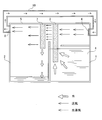
- FIG. 1 is a schematic configuration diagram showing the overall configuration of the fresh water generation apparatus.
- a first storage tank 1 in which a storage liquid 4 such as seawater, sludge water, and oil water is stored, and a second storage tank 2 are provided adjacent to the storage tank 1.
- a first porous water-absorbing substrate 3 serving as a water-absorbing base material in which each pore diameter having a porous structure is formed in the size of a water molecule is disposed at the lower boundary of the storage tank 1 adjacent to the storage tank 2.
- a part is suspended from a lid 5 provided to seal the upper space of the storage tank 1 and the storage tank 2 while being immersed in the storage liquid 4 stored in the storage tank 1.
- a blower 6 that blows air toward the upper side of the first porous water-absorbing substrate 3 that is not immersed in the storage liquid 4 is installed on the inner front wall surface of the lid 5.
- a second porous water-absorbing substrate 7 as a water-absorbing base material in which each pore diameter having a porous structure is formed to the size of water molecules, At a position facing the porous water absorbent substrate 3, the lower end thereof is suspended from the lid 5 so as to face the inside of the storage tank 2.
- An exhaust port 8 is formed on the inner rear wall surface of the lid 5 that seals the second storage tank 2 side. The exhaust port 8 passes over the lid 5 and is provided on the above-described blower 6 side.
- a conducting tube 10 communicating with the intake port 9 is provided.
- the first and second porous water-absorbing substrates 3 and 7 described above use a specially configured firing furnace that can be heated in increments of 1 ° C. in a high temperature range of 800 to 2000 ° C. developed by the present applicant.
- each pore diameter of the porous structure is made of synthetic zeolite formed to the same diameter as water molecules.
- the water vapor can be condensed and extracted as distilled water.
- a water-absorbing base material that exhibits the same function a nanocarbon material can be used, or a fabric woven into a water molecular diameter can be used.
- the fresh water generation function of the fresh water generation apparatus configured as described above will be described. Since the lower end portion of the first porous water-absorbing substrate 3 is immersed in the storage liquid 4 stored in the storage tank 1, only the moisture in the storage liquid 4 is instantaneously contained throughout the porous water-absorbing substrate 3. To penetrate. Since the blower 6 continues to blow air (indicated by an arrow in the figure) to the front surface side of the first porous water-absorbing substrate 3, moisture that continues to permeate the inside 3 of the substrate is sequentially vaporized and the back surface of the substrate 3. It is sent out from the side as water vapor (indicated by broken arrows in the figure).
- the water vapor sent out in this way reaches the front surface of the second porous water-absorbing substrate 7 suspended on the second storage tank 2 side, penetrates into the second porous substrate 7, and the substrate As it permeates into the inside, the heat is sequentially released and condensed, and drops as fresh water droplets (indicated by white arrows in the figure) from the lower end side of the substrate 7. Fresh water is stored.
- the blown air is exhausted from the exhaust port 8 provided in the rear inner wall surface of the lid 5 that seals the storage tank 2, and is sent to the intake port 9 provided in the blower 6 through the conducting pipe 10 to be refluxed. At this time, the blast itself becomes dry air while the temperature is increased by the heat released by condensation of water vapor.
- the substrate Since the air recirculated to the intake port 9 side of the blower 6 is blown to the first porous water-absorbing substrate 3 as dry air having a higher temperature than before the circulation cycle, the substrate is more than the previous substrate.
- the vaporization phenomenon is further promoted with respect to the water that has permeated into the water 3, and only water is efficiently absorbed from the storage liquid 4 in the storage tank 1, and the vaporized water vapor becomes the second porous water-absorbing substrate 7.
- the amount of droplets that are adsorbed and condensed in the storage tank 2 increases.
- the storage tank 1 is replenished from a supply path (not shown), and when the fresh water stored in the storage tank 2 increases, it is taken out from the intake path (not shown).
- the fresh water generating apparatus is a synthetic zeolite calcined by a special component blend in which each pore diameter of the porous structure developed by the present applicant is formed to the same diameter as water molecules,
- a porous water-absorbing substrate capable of instantaneously adsorbing moisture
- Vaporized by blowing air, adsorbed and condensed vaporized water vapor, and stored in the storage tank 2 so that a large amount of heat energy is not required, replacement of the substrate itself is not necessary, Can be produced efficiently under Since the amount of fresh water generated can be controlled only by adjusting the amount of air blown by the air blowing means, a basic device configuration can be realized very simply and at low cost with respect to a normal storage tank.
- the first and second porous water-absorbing substrates 3 and 7 in the above embodiment are connected to each other on the upper side adjacent surface and are integrally formed in an inverted U-shape.
- the configuration can be achieved.
- the lower end portion of the first porous water-absorbing substrate 3 may be formed shorter than the lower end portion of the second porous water-absorbing substrate 7 in consideration of the conduit capillary phenomenon.
- an air cooler that is a so-called ultra-low temperature air generator is installed, compressed air is supplied to the air cooler, and cold air injected from the air cooler is supplied to the second storage tank 2 and the air cooler. If the hot air exhausted from the fan 6 is supplied to the intake side of the blower 6, the air recirculated to the intake side of the blower 6 is blown to the first porous water-absorbing substrate 3 as hot air having a further increased temperature, The vaporization phenomenon is further promoted, and ultra-low temperature air is supplied into the second storage tank 2, and the temperature of the second porous water-absorbing substrate 7 is lowered to further promote the condensation of water vapor. Thus, the production efficiency of fresh water can be increased.
- the heat transfer efficiency to the storage liquid 4 itself is not lowered by appropriately supplementing the storage liquid so that the liquid level of the storage liquid 4 stored in the first storage tank 1 is stored as low as possible.
- a plurality of metal bowl-like members (not shown) are suspended in the second storage tank 2, when the inside of the storage tank 2 is cooled with cold air, the water vapor staying in the storage tank 2 is also related to the bowl-like member. Therefore, the production efficiency of fresh water can be further increased.
- drinking water can be obtained by heating or ozone treatment of fresh water generated from seawater and adding minerals. Moreover, even if it is contaminated water contaminated with arsenic etc., a contaminant can be removed similarly and drinking water can be obtained.
- industrial wastewater where BOD and COD are a problem can be drained without any problems by using this equipment for wastewater treatment. Will be able to do.
Landscapes
- Chemical & Material Sciences (AREA)
- Chemical Kinetics & Catalysis (AREA)
- Water Supply & Treatment (AREA)
- Hydrology & Water Resources (AREA)
- Engineering & Computer Science (AREA)
- Environmental & Geological Engineering (AREA)
- Life Sciences & Earth Sciences (AREA)
- Organic Chemistry (AREA)
- Inorganic Chemistry (AREA)
- Analytical Chemistry (AREA)
- Heat Treatment Of Water, Waste Water Or Sewage (AREA)
- Vaporization, Distillation, Condensation, Sublimation, And Cold Traps (AREA)
- Water Treatment By Sorption (AREA)
- Solid-Sorbent Or Filter-Aiding Compositions (AREA)
Abstract
Description
2 第二の貯蔵槽
3 第一の多孔質吸水基板
4 貯蔵液
5 蓋体
6 送風機
7 第二の多孔質吸水基板
8 排気口
9 吸気口
10 導通管
Claims (8)
- 海水、汚泥水、油水、工業用排水などの貯蔵液が収容された第一の貯蔵槽と、
下端部が第一の貯蔵槽の貯蔵液内に浸漬された第一の吸水基材と、
当該第一の吸水基材の上端部側に対して送風する送風手段と、
当該送風手段による送風によって、前記第一の吸水基材の上端部側から気化して吹き出される水蒸気を上端部側で吸着するとともに凝結させ、凝結した水滴が下端部側から落滴するようにした第二の吸水基材と、
当該第二の吸水基材下端部側から落滴する凝結水が貯蔵される第二の貯蔵槽と、
これら第一及び第二の貯蔵槽上部空間を密閉する蓋体と、
当該蓋体の第二の貯蔵槽上部空間に一端部が連通し、前記送風手段からの送風を排気するとともに、他端部が第一の貯蔵槽上部空間に連通し前記送風手段の吸気側へ連通して送風の循環路となる導通管とからなることを特徴とする真水生成装置。 - 第一及び第二の吸水基材が、多孔質構造の各孔径が水分子の大きさに形成された合成ゼオライトからなる請求項1に記載の真水生成装置。
- 第一及び第二の吸水基材が、多孔質構造の各孔径が水分子の大きさに形成されたナノカーボンからなる請求項1に記載の真水生成装置。
- 第一及び第二の吸水基材が、吸水性に優れた布地からなる請求項1に記載の真水生成装置。
- 第一及び第二の吸水基材が、これらが配置された上部側隣接面で連結し逆U字型に一体形成されてなる請求項1乃至4に記載の真水生成装置。
- エアークーラーを設置し、当該エアークーラーに圧縮空気を供給し、エアークーラーから噴射される冷気を前記第二の貯蔵槽内に供給するとともに、エアークーラーから排気される熱気を前記送風手段の吸気側へ供給するようにした請求項1乃至5に記載の真水生成装置。
- 第一の貯蔵槽に貯蔵される貯蔵液の液位を極力低くして貯蔵するようにした請求項1乃至6に記載の真水生成装置。
- 第二の貯蔵槽内に、当該貯蔵槽内に滞留する水蒸気を凝結させるための鰭状部材を複数吊設した請求項1乃至7に記載の真水生成装置。
Priority Applications (6)
| Application Number | Priority Date | Filing Date | Title |
|---|---|---|---|
| US15/556,346 US10625174B2 (en) | 2015-03-10 | 2016-03-10 | Fresh-water generating apparatus |
| JP2016543764A JP6391698B2 (ja) | 2015-03-10 | 2016-03-10 | 真水生成装置 |
| EP16761814.9A EP3269686A4 (en) | 2015-03-10 | 2016-03-10 | Fresh water-generating apparatus |
| CN201680014569.0A CN107428561B (zh) | 2015-03-10 | 2016-03-10 | 淡水生成装置 |
| SG11201708187SA SG11201708187SA (en) | 2015-03-10 | 2016-03-10 | Fresh-water generating apparatus |
| IL254314A IL254314B (en) | 2015-03-10 | 2017-09-04 | Fresh water generating device |
Applications Claiming Priority (2)
| Application Number | Priority Date | Filing Date | Title |
|---|---|---|---|
| JP2015-047132 | 2015-03-10 | ||
| JP2015047132 | 2015-03-10 |
Publications (1)
| Publication Number | Publication Date |
|---|---|
| WO2016143848A1 true WO2016143848A1 (ja) | 2016-09-15 |
Family
ID=56879574
Family Applications (1)
| Application Number | Title | Priority Date | Filing Date |
|---|---|---|---|
| PCT/JP2016/057553 Ceased WO2016143848A1 (ja) | 2015-03-10 | 2016-03-10 | 真水生成装置 |
Country Status (7)
| Country | Link |
|---|---|
| US (1) | US10625174B2 (ja) |
| EP (1) | EP3269686A4 (ja) |
| JP (1) | JP6391698B2 (ja) |
| CN (1) | CN107428561B (ja) |
| IL (1) | IL254314B (ja) |
| SG (1) | SG11201708187SA (ja) |
| WO (1) | WO2016143848A1 (ja) |
Cited By (4)
| Publication number | Priority date | Publication date | Assignee | Title |
|---|---|---|---|---|
| JP2019018151A (ja) * | 2017-07-18 | 2019-02-07 | 株式会社ワンワールド | 真水生成装置 |
| JP2019081143A (ja) * | 2017-10-31 | 2019-05-30 | 株式会社ワンワールド | 水処理装置 |
| JP2020081950A (ja) * | 2018-11-22 | 2020-06-04 | 博 前島 | 排水浄化処理装置 |
| JP2024507632A (ja) * | 2020-12-31 | 2024-02-21 | クリスタル ラグーンズ テクノロジーズ,インコーポレイテッド | 部分的閉じ込めシステムを有する大きな水塊用の局所化された加熱システム |
Families Citing this family (2)
| Publication number | Priority date | Publication date | Assignee | Title |
|---|---|---|---|---|
| CN114305071B (zh) * | 2020-10-10 | 2023-03-03 | 佛山市顺德区美的电热电器制造有限公司 | 烹饪器具的盖板、烹饪器具和盖板的制造方法 |
| PL445831A1 (pl) * | 2023-08-14 | 2025-02-17 | Rapa S.Międlar W. I I.Szymańscy Spółka Jawna | Urządzenie do ewaporacji skroplin |
Citations (6)
| Publication number | Priority date | Publication date | Assignee | Title |
|---|---|---|---|---|
| JPH02191586A (ja) * | 1989-01-19 | 1990-07-27 | Kawanami Shunpei | 海水の淡水化装置 |
| GB2330779A (en) * | 1997-10-29 | 1999-05-05 | Alan Roy Filewood | Desalination of water |
| WO2004067451A1 (de) * | 2003-01-27 | 2004-08-12 | Rudolf Schober | Vorrichtung zum teinigen von wasser |
| GB2400603A (en) * | 2003-04-15 | 2004-10-20 | Alan Roy Filewood | Desalination apparatus and method |
| JP2011031157A (ja) * | 2009-07-31 | 2011-02-17 | Re Earth:Kk | 淡水製造装置 |
| JP2012040454A (ja) * | 2010-08-12 | 2012-03-01 | M Hikari Energy Kaihatsu Kenkyusho:Kk | 海水の淡水化装置及び含水物の脱水方法 |
Family Cites Families (21)
| Publication number | Priority date | Publication date | Assignee | Title |
|---|---|---|---|---|
| US1082411A (en) * | 1912-07-30 | 1913-12-23 | Donato Cozzolino | Evaporating apparatus. |
| GB333547A (en) * | 1929-02-14 | 1930-08-14 | Guy Erskine Hughes | Improvements in and relating to the distillation of water |
| US2445350A (en) * | 1943-12-23 | 1948-07-20 | Defoe C Ginnings | Multiple-effect solar still |
| NL292611A (ja) * | 1962-05-11 | |||
| US3878054A (en) * | 1964-12-09 | 1975-04-15 | Pactide Corp | Distillation apparatus and process |
| JPS57147096A (en) | 1981-03-06 | 1982-09-10 | Yoshimi Oshitari | Device of processing radioactive liquid waste |
| JPS6230501A (ja) | 1985-07-31 | 1987-02-09 | Ishikawajima Harima Heavy Ind Co Ltd | 溶解物質の濃縮分離装置 |
| JPH0389990A (ja) | 1989-06-26 | 1991-04-15 | Fuji Photo Film Co Ltd | 写真処理廃液処理装置 |
| US5203161A (en) * | 1990-10-30 | 1993-04-20 | Lehto John M | Method and arrangement for cooling air to gas turbine inlet |
| JPH1071320A (ja) | 1996-08-30 | 1998-03-17 | Koichi Nakamura | 水資源造出装置 |
| WO2000063671A1 (en) * | 1999-04-17 | 2000-10-26 | Genevac Limited | Evaporation of liquids and recirculation of purified gas |
| DE10334514A1 (de) * | 2003-07-29 | 2005-02-24 | Pfleiderer Infrastrukturtechnik Gmbh & Co Kg | Verwendung inerter, poröser Materialien zur Reduzierung des Salzgehalts in wässrigen Lösungen sowie Verfahren und Vorrichtung hierfür |
| US20080066874A1 (en) | 2006-09-19 | 2008-03-20 | Mohinder Singh Bhatti | High efficiency water desalinator |
| JP4113568B1 (ja) | 2007-11-19 | 2008-07-09 | 株式会社神鋼環境ソリューション | 飲料水製造用水処理システム及びその運転方法 |
| US20100288619A1 (en) * | 2008-01-18 | 2010-11-18 | Takashi Yabe | Energy-Saving Type Apparatus For Producing Freshwater |
| JP2011245478A (ja) * | 2010-04-27 | 2011-12-08 | Yoshinobu Miyashita | 海水淡水化装置 |
| JP5762041B2 (ja) * | 2011-02-17 | 2015-08-12 | 株式会社日立製作所 | 複合淡水化システム |
| CA2846133C (en) * | 2011-08-22 | 2021-01-19 | Brian PEEVER | Dewatering method using a wicking material |
| US8496234B1 (en) * | 2012-07-16 | 2013-07-30 | Massachusetts Institute Of Technology | Thermodynamic balancing of combined heat and mass exchange devices |
| US9440862B1 (en) * | 2013-04-29 | 2016-09-13 | Shafiq ur Rahman | Method and apparatus for accelerated open air evaporation of wastewater |
| US11442926B2 (en) | 2018-09-05 | 2022-09-13 | Nhn Corporation | Method and system for storing driving record data based on block chain |
-
2016
- 2016-03-10 JP JP2016543764A patent/JP6391698B2/ja active Active
- 2016-03-10 US US15/556,346 patent/US10625174B2/en active Active
- 2016-03-10 CN CN201680014569.0A patent/CN107428561B/zh active Active
- 2016-03-10 EP EP16761814.9A patent/EP3269686A4/en not_active Withdrawn
- 2016-03-10 WO PCT/JP2016/057553 patent/WO2016143848A1/ja not_active Ceased
- 2016-03-10 SG SG11201708187SA patent/SG11201708187SA/en unknown
-
2017
- 2017-09-04 IL IL254314A patent/IL254314B/en active IP Right Grant
Patent Citations (6)
| Publication number | Priority date | Publication date | Assignee | Title |
|---|---|---|---|---|
| JPH02191586A (ja) * | 1989-01-19 | 1990-07-27 | Kawanami Shunpei | 海水の淡水化装置 |
| GB2330779A (en) * | 1997-10-29 | 1999-05-05 | Alan Roy Filewood | Desalination of water |
| WO2004067451A1 (de) * | 2003-01-27 | 2004-08-12 | Rudolf Schober | Vorrichtung zum teinigen von wasser |
| GB2400603A (en) * | 2003-04-15 | 2004-10-20 | Alan Roy Filewood | Desalination apparatus and method |
| JP2011031157A (ja) * | 2009-07-31 | 2011-02-17 | Re Earth:Kk | 淡水製造装置 |
| JP2012040454A (ja) * | 2010-08-12 | 2012-03-01 | M Hikari Energy Kaihatsu Kenkyusho:Kk | 海水の淡水化装置及び含水物の脱水方法 |
Non-Patent Citations (1)
| Title |
|---|
| See also references of EP3269686A4 * |
Cited By (5)
| Publication number | Priority date | Publication date | Assignee | Title |
|---|---|---|---|---|
| JP2019018151A (ja) * | 2017-07-18 | 2019-02-07 | 株式会社ワンワールド | 真水生成装置 |
| JP2019081143A (ja) * | 2017-10-31 | 2019-05-30 | 株式会社ワンワールド | 水処理装置 |
| JP7053218B2 (ja) | 2017-10-31 | 2022-04-12 | 株式会社ワンワールド | 水処理装置 |
| JP2020081950A (ja) * | 2018-11-22 | 2020-06-04 | 博 前島 | 排水浄化処理装置 |
| JP2024507632A (ja) * | 2020-12-31 | 2024-02-21 | クリスタル ラグーンズ テクノロジーズ,インコーポレイテッド | 部分的閉じ込めシステムを有する大きな水塊用の局所化された加熱システム |
Also Published As
| Publication number | Publication date |
|---|---|
| US20180043277A1 (en) | 2018-02-15 |
| EP3269686A1 (en) | 2018-01-17 |
| SG11201708187SA (en) | 2017-11-29 |
| US10625174B2 (en) | 2020-04-21 |
| JPWO2016143848A1 (ja) | 2018-02-08 |
| IL254314A0 (en) | 2017-11-30 |
| IL254314B (en) | 2021-01-31 |
| JP6391698B2 (ja) | 2018-09-19 |
| CN107428561A (zh) | 2017-12-01 |
| CN107428561B (zh) | 2021-04-02 |
| EP3269686A4 (en) | 2018-09-12 |
Similar Documents
| Publication | Publication Date | Title |
|---|---|---|
| JP6391698B2 (ja) | 真水生成装置 | |
| RU2648333C2 (ru) | Многоступенчатый барботажный колонный увлажнитель | |
| KR102424159B1 (ko) | 기포 컬럼 응축기와 같은 응축 장치를 포함하는 시스템 | |
| US9630862B2 (en) | Desalination system and method for desalination | |
| CN109020031B (zh) | 一种基于热力压缩的蒸发浓缩系统 | |
| BRPI0712138A2 (pt) | método para destilação com coluna mutiestágio (mscd) para recuperação de soluto osmótico | |
| JP5943924B2 (ja) | 浸透圧駆動膜プロセス及びシステム、並びに引出溶質回収方法 | |
| WO2012121675A1 (en) | A regenerative adsorption distillation system | |
| CN101564649A (zh) | 一种压气膜蒸馏装置与方法 | |
| KR100659375B1 (ko) | 무화증기를 이용한 해수 담수화 장치 | |
| KR101394517B1 (ko) | 담수화 장치 | |
| JP2015020163A (ja) | ナノファイバー膜蒸留装置 | |
| KR101672852B1 (ko) | 2중 열원을 이용한 해수담수화 시스템 | |
| CN102371120B (zh) | 多级式减压膜蒸馏组件单元装置及其膜蒸馏装置与方法 | |
| JP3235878U (ja) | 真水生成装置 | |
| KR101620099B1 (ko) | 태양열과 폐열 에너지를 혼용한 분산형 해수담수화 시스템 | |
| JP4996068B2 (ja) | 廃水の濃縮処理方法及びその装置 | |
| TWI716412B (zh) | 淡水生成裝置 | |
| KR20260002770A (ko) | 액체상의 유체를 정제하기 위한 장치 및 방법 | |
| JP2025133106A (ja) | 浄化処理装置 | |
| JP2019018151A (ja) | 真水生成装置 | |
| KR20230033067A (ko) | 진공 및 멤브레인 방식을 적용한 담수화 장치 | |
| KR20060061431A (ko) | 해수담수화설비용 탈기기의 컴팩트 구조 | |
| JP2019081143A (ja) | 水処理装置 |
Legal Events
| Date | Code | Title | Description |
|---|---|---|---|
| ENP | Entry into the national phase |
Ref document number: 2016543764 Country of ref document: JP Kind code of ref document: A |
|
| 121 | Ep: the epo has been informed by wipo that ep was designated in this application |
Ref document number: 16761814 Country of ref document: EP Kind code of ref document: A1 |
|
| WWE | Wipo information: entry into national phase |
Ref document number: 254314 Country of ref document: IL |
|
| WWE | Wipo information: entry into national phase |
Ref document number: 15556346 Country of ref document: US |
|
| NENP | Non-entry into the national phase |
Ref country code: DE |
|
| WWE | Wipo information: entry into national phase |
Ref document number: 11201708187S Country of ref document: SG |
|
| REEP | Request for entry into the european phase |
Ref document number: 2016761814 Country of ref document: EP |