WO2016147604A1 - ガラスパネルユニットの製造方法、ガラス窓の製造方法、およびスペーサ付きガラス基板の製造装置 - Google Patents
ガラスパネルユニットの製造方法、ガラス窓の製造方法、およびスペーサ付きガラス基板の製造装置 Download PDFInfo
- Publication number
- WO2016147604A1 WO2016147604A1 PCT/JP2016/001250 JP2016001250W WO2016147604A1 WO 2016147604 A1 WO2016147604 A1 WO 2016147604A1 JP 2016001250 W JP2016001250 W JP 2016001250W WO 2016147604 A1 WO2016147604 A1 WO 2016147604A1
- Authority
- WO
- WIPO (PCT)
- Prior art keywords
- glass substrate
- spacer
- glass
- panel unit
- manufacturing
- Prior art date
- Legal status (The legal status is an assumption and is not a legal conclusion. Google has not performed a legal analysis and makes no representation as to the accuracy of the status listed.)
- Ceased
Links
Images






Classifications
-
- C—CHEMISTRY; METALLURGY
- C03—GLASS; MINERAL OR SLAG WOOL
- C03C—CHEMICAL COMPOSITION OF GLASSES, GLAZES OR VITREOUS ENAMELS; SURFACE TREATMENT OF GLASS; SURFACE TREATMENT OF FIBRES OR FILAMENTS MADE FROM GLASS, MINERALS OR SLAGS; JOINING GLASS TO GLASS OR OTHER MATERIALS
- C03C27/00—Joining pieces of glass to pieces of other inorganic material; Joining glass to glass other than by fusing
- C03C27/06—Joining glass to glass by processes other than fusing
- C03C27/10—Joining glass to glass by processes other than fusing with the aid of adhesive specially adapted for that purpose
-
- C—CHEMISTRY; METALLURGY
- C03—GLASS; MINERAL OR SLAG WOOL
- C03C—CHEMICAL COMPOSITION OF GLASSES, GLAZES OR VITREOUS ENAMELS; SURFACE TREATMENT OF GLASS; SURFACE TREATMENT OF FIBRES OR FILAMENTS MADE FROM GLASS, MINERALS OR SLAGS; JOINING GLASS TO GLASS OR OTHER MATERIALS
- C03C27/00—Joining pieces of glass to pieces of other inorganic material; Joining glass to glass other than by fusing
- C03C27/06—Joining glass to glass by processes other than fusing
-
- E—FIXED CONSTRUCTIONS
- E06—DOORS, WINDOWS, SHUTTERS, OR ROLLER BLINDS IN GENERAL; LADDERS
- E06B—FIXED OR MOVABLE CLOSURES FOR OPENINGS IN BUILDINGS, VEHICLES, FENCES OR LIKE ENCLOSURES IN GENERAL, e.g. DOORS, WINDOWS, BLINDS, GATES
- E06B3/00—Window sashes, door leaves, or like elements for closing wall or like openings; Layout of fixed or moving closures, e.g. windows in wall or like openings; Features of rigidly-mounted outer frames relating to the mounting of wing frames
- E06B3/66—Units comprising two or more parallel glass or like panes permanently secured together
- E06B3/6612—Evacuated glazing units
-
- E—FIXED CONSTRUCTIONS
- E06—DOORS, WINDOWS, SHUTTERS, OR ROLLER BLINDS IN GENERAL; LADDERS
- E06B—FIXED OR MOVABLE CLOSURES FOR OPENINGS IN BUILDINGS, VEHICLES, FENCES OR LIKE ENCLOSURES IN GENERAL, e.g. DOORS, WINDOWS, BLINDS, GATES
- E06B3/00—Window sashes, door leaves, or like elements for closing wall or like openings; Layout of fixed or moving closures, e.g. windows in wall or like openings; Features of rigidly-mounted outer frames relating to the mounting of wing frames
- E06B3/66—Units comprising two or more parallel glass or like panes permanently secured together
- E06B3/663—Elements for spacing panes
-
- E—FIXED CONSTRUCTIONS
- E06—DOORS, WINDOWS, SHUTTERS, OR ROLLER BLINDS IN GENERAL; LADDERS
- E06B—FIXED OR MOVABLE CLOSURES FOR OPENINGS IN BUILDINGS, VEHICLES, FENCES OR LIKE ENCLOSURES IN GENERAL, e.g. DOORS, WINDOWS, BLINDS, GATES
- E06B3/00—Window sashes, door leaves, or like elements for closing wall or like openings; Layout of fixed or moving closures, e.g. windows in wall or like openings; Features of rigidly-mounted outer frames relating to the mounting of wing frames
- E06B3/66—Units comprising two or more parallel glass or like panes permanently secured together
- E06B3/663—Elements for spacing panes
- E06B3/66304—Discrete spacing elements, e.g. for evacuated glazing units
-
- E—FIXED CONSTRUCTIONS
- E06—DOORS, WINDOWS, SHUTTERS, OR ROLLER BLINDS IN GENERAL; LADDERS
- E06B—FIXED OR MOVABLE CLOSURES FOR OPENINGS IN BUILDINGS, VEHICLES, FENCES OR LIKE ENCLOSURES IN GENERAL, e.g. DOORS, WINDOWS, BLINDS, GATES
- E06B3/00—Window sashes, door leaves, or like elements for closing wall or like openings; Layout of fixed or moving closures, e.g. windows in wall or like openings; Features of rigidly-mounted outer frames relating to the mounting of wing frames
- E06B3/66—Units comprising two or more parallel glass or like panes permanently secured together
- E06B3/677—Evacuating or filling the gap between the panes ; Equilibration of inside and outside pressure; Preventing condensation in the gap between the panes; Cleaning the gap between the panes
- E06B3/6775—Evacuating or filling the gap during assembly
Definitions
- the present invention relates to a technique for manufacturing a glass panel unit, and more particularly, to a technique for manufacturing a glass panel unit in which a spacer is sandwiched between a pair of glass substrates.
- Patent Document 1 describes a glass panel unit in which a spacer is sandwiched between a pair of plate glasses.
- spacers manufactured in a columnar shape in advance are arranged on a plate glass (glass substrate) in a predetermined arrangement.
- Another glass plate (glass substrate) is stacked on the glass plate on which the spacer is disposed, whereby a glass panel unit in which the spacer is sandwiched between a pair of glass plates is obtained.
- the problem to be solved by the present invention is to efficiently manufacture a glass panel unit in which a spacer is sandwiched between a pair of glass substrates.
- the manufacturing method of the glass panel unit which concerns on 1 aspect of this invention comprises the following structure.
- the setting step is a step in which the first glass substrate, the punching die provided with the penetrating portion, the sheet material, and the punch portion are set so as to be arranged in this order.
- the spacer forming step when the punch part is driven into the sheet material, a part of the sheet material is punched through the through part of the punching die, and the punched part is It is a process which is arrange
- a second glass substrate is stacked on the first glass substrate so as to sandwich the spacer, and an inner space where the spacer is located between the first glass substrate and the second glass substrate. Is a step of forming.
- the manufacturing method of the glass window which concerns on 1 aspect of this invention is equipped with the assembly process which inserts a window frame in the glass panel unit manufactured with the manufacturing method of the glass panel unit which concerns on 1 aspect of this invention.
- the manufacturing apparatus of the glass substrate with a spacer which concerns on 1 aspect of this invention comprises the following structure.
- the apparatus for manufacturing a glass substrate with a spacer is an apparatus for manufacturing a glass substrate with a spacer that constitutes a part of the glass panel unit, and a substrate placement unit on which the glass substrate is disposed, A punching die having a penetrating part and a punching part are provided.
- the punch portion is provided so as to punch out the sheet material placed on the punching die through the through portion.
- the punching die is located between the substrate placement portion and the punch portion.
- a part of the sheet material punched by the punch portion is disposed on the glass substrate by the punch portion, and is provided so as to constitute a spacer.
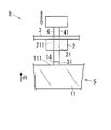
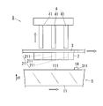
- FIG. 1 is a side view schematically showing the manufacturing apparatus of the first embodiment.
- FIG. 2 is a side view schematically showing how the sheet material is punched out by the manufacturing apparatus of the first embodiment.
- FIG. 3 is a side view schematically showing how the sheet material and the glass substrate move in the manufacturing apparatus of the first embodiment.
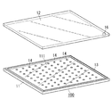
- FIG. 4 is a perspective view showing a glass substrate with a spacer manufactured by the manufacturing apparatus of Embodiment 1 and a glass substrate bonded thereto.
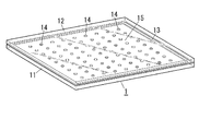
- FIG. 5 is a perspective view showing a glass panel unit formed using a glass substrate with a spacer manufactured by the manufacturing apparatus according to the first embodiment.
- FIG. 6 is a flowchart showing the manufacturing method of the first embodiment.
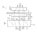
- FIG. 7 is a perspective view schematically showing the manufacturing apparatus of the second embodiment.
- FIG. 8 is a side view schematically showing how the sheet material is punched out by the manufacturing apparatus of the second embodiment.
- FIG. 9 is a side view schematically showing how the sheet material and the glass substrate move in the manufacturing apparatus of the second embodiment.
- FIG. 10 is a plan view showing a glass panel unit manufactured by the manufacturing method of the third embodiment. 11 is a cross-sectional view taken along line AA in FIG.
- FIG. 12 is a flowchart showing the manufacturing method of the third embodiment.
- FIG. 13 is a plan view showing a glass window including the glass panel unit of the first embodiment.
- FIG. 14 is a flowchart showing a method for manufacturing a glass window including the glass panel unit of the first embodiment.
- the manufacturing apparatus 9 is an apparatus for manufacturing a glass substrate 100 with a spacer (see FIG. 4).
- the glass substrate 100 with spacers constitutes a part of the glass panel unit 1, and specifically has a structure in which a plurality of spacers 14 are arranged on one surface 111 of the glass substrate 11.
- Another glass substrate 12 is stacked on the glass substrate with spacer 100 so as to face the one surface 111 of the glass substrate 11, and a gap between the opposing glass substrates 11, 12 is sealed with a frame-shaped sealing material 13.
- the glass panel unit 1 (see FIG. 5) is obtained.
- the glass substrate 11 constituting the glass substrate with spacer 100 is referred to as a “first glass substrate”, and the same reference numeral 11 is given.
- the glass substrate 12 overlaid on the glass substrate with spacer 100 is referred to as a “second glass substrate”, and is given the same reference numeral 12.
- the manufacturing apparatus 9 includes a substrate placement portion 5, a punching die 2, and a punch portion 4. 1 to 3, the direction in which the arrow d1 peels is the upward direction, and the direction to the opposite of the arrow d1 is the downward direction.
- the first glass substrate 11 is supported on the substrate placement unit 5 in a predetermined posture with the one surface 111 facing upward.
- the punching die 2 is located above the substrate placement portion 5.
- the die 2 is positioned above the one surface 111 of the first glass substrate 11 supported by the substrate placement portion 5.
- the punching die 2 has a through portion 21.
- the penetrating part 21 is composed of one through hole 211 penetrating vertically.
- the sheet material 3 is placed on the upper surface of the punching die 2 so as to cover the through hole 211.
- the punch 4 is located above the punch 2.
- the punch portion 4 includes a columnar punch 41 that protrudes downward.
- the punch 41 is a portion for punching the sheet material 3 placed on the punching die 2 downward through the through hole 211.
- the manufacturing method of this embodiment includes a setting step S1, a spacer forming step S2, a displacement step S3, an assembly step S4, and a processing step S5.
- the assembly process S4 and the processing process S5 are performed after the spacer formation process S2 is repeatedly performed a plurality of times with the displacement process S3 interposed therebetween.
- the first glass substrate 11, the punching die 2, the sheet material 3, and the punch portion 4 are set so as to be positioned from bottom to top in this order (see FIG. 1).
- the sheet material 3 is put on the upper surface of the die 2.
- the punch 41 constituting the punch portion 4 is positioned directly above the through hole 211 provided in the punching die 2 with the sheet material 3 interposed therebetween.
- the punch portion 4 is driven in a straight track toward the lower side.
- the columnar punch 41 punches a part 31 of the sheet material 3 downward through the through hole 211 of the punching die 2 (see the white arrow in FIG. 2).
- the part 31 of the sheet material 3 punched out by the punch 41 is pressed against the one surface 111 of the first glass substrate 11 in a state where it hits the front end surface of the punch 41.
- the part 31 of the sheet material 3 is temporarily fixed on the one surface 111 by being pressed onto the one surface 111 of the first glass substrate 11 by a predetermined pressure by the tip surface of the punch 41 for a predetermined time.
- a part 31 of the temporarily fixed sheet material 3 constitutes a spacer 14 on one surface 111.
- the spacer forming step S2 is executed again, whereby another part 31 of the sheet material 3 is punched out, and the other part 31 is the first part.
- Another spacer 14 is formed by being temporarily fixed on one surface 111 of one glass substrate 11.
- the spacer forming step S2 is repeatedly performed a plurality of times with the displacement step S3 interposed therebetween.
- the spacer forming step S2 is performed a plurality of times while the relative position between the punch portion 4 and the first glass substrate 11 is changed, so that the plurality of spacers 14 are separated from each other on the one surface 111 of the first glass substrate 11. It is formed with a gap.
- the glass substrate 100 with a spacer provided with the plurality of spacers 14 is efficiently manufactured.
- the spacers may be adsorbed due to static electricity or the like. Is suppressed. Therefore, there is an advantage that the degree of freedom of the material of the spacer 14 (the material of the sheet material 3) is increased.
- the frame-shaped sealing material 13 is disposed on the peripheral portion of the one surface 111 of the first glass substrate 11 constituting the glass substrate with spacer 100.
- the sealing material 13 is positioned on the first surface 111 of the first glass substrate 11 so as to surround the plurality of spacers 14.
- the second glass substrate 12 is stacked on the first glass substrate 11 so as to sandwich the plurality of spacers 14 and the sealing material 13, and the first glass substrate 11 and the second glass substrate 11 are interposed via the sealing material 13.
- the glass substrate 12 is bonded.
- An internal space 15 is formed between the joined first glass substrate 11 and second glass substrate 12 (see FIG. 5).
- a plurality of spacers 14 are located in the internal space 15. Each of the plurality of spacers 14 is in contact with the second glass substrate 12 and maintains the distance between the first glass substrate 11 and the second glass substrate 12.
- the internal space 15 is decompressed until reaching a predetermined degree of vacuum through the vent hole 16 (see FIG. 4) provided in the second glass substrate 12, or gas (dry air, argon, etc.) is supplied to the internal space 15. Is supplied, and then the vent hole 16 is sealed.
- gas dry air, argon, etc.
- the glass panel unit 1 shown in FIG. 5 is formed through the processing step S5.
- the glass panel unit 1 includes an internal space 15 sealed between the first glass substrate 11 and the second glass substrate 12 in a state where the pressure is reduced or gas is supplied.
- the glass panel unit 1 is provided with the internal space 15 and thus has high heat insulating properties.
- the internal space 15 may not be decompressed and gas may not be supplied. That is, the glass panel unit 1 may be formed by a manufacturing method that does not include the processing step S5. The glass panel unit 1 formed by the manufacturing method in this case also has heat insulation.
- a large number of spacers 14 are arranged at approximately equal intervals between the first glass substrate 11 and the second glass substrate 12, but the number and positions of the spacers 14 are not particularly limited.
- One spacer 14 may be disposed on one surface 111 of the first glass substrate 11.
- (Embodiment 2) 7 to 9 schematically show the manufacturing apparatus 9 according to the second embodiment.
- the same configurations as those of the first embodiment are denoted by the same reference numerals, detailed description thereof is omitted, and configurations different from those of the first embodiment are described in detail.
- the through part 21 included in the manufacturing apparatus 9 of the present embodiment includes a plurality of through holes 211 positioned at a distance from each other.
- the plurality of through-holes 211 have the same size and shape.
- the plurality of through holes 211 are arranged in a matrix in a plan view (when viewed from above).
- the punch part 4 with which the manufacturing apparatus 9 of this embodiment is provided is comprised with the some punch 41 located mutually spaced apart.
- the plurality of punches 41 have the same size and shape.
- the plurality of punches 41 are arranged in a matrix in a plan view.
- the arrangement pattern of the plurality of punches 41 matches the arrangement pattern of the plurality of through holes 211 in plan view.
- the plurality of punches 41 can enter one-to-one with respect to the plurality of through holes 211 positioned below.
- the manufacturing method of the present embodiment includes a setting step S1, a spacer forming step S2, a displacement step S3, an assembly step S4, and a processing step S5.
- a setting step S1 a spacer forming step S2
- a displacement step S3 a displacement step S3
- an assembly step S4 a processing step S5.
- the first glass substrate 11, the die 2, the sheet material 3, and the punch portion 4 are set so as to be positioned in this order.
- the plurality of through-holes 211 provided in the punching die 2 and the plurality of punches 41 provided in the punch portion 4 are positioned one-on-one so as to face each other (see FIG. 7).
- a plurality of punches 41 included in the punch portion 4 are integrally driven into the sheet material 3 (see white arrows in FIG. 8). Accordingly, the plurality of portions 311 of the sheet material 3 are punched through the plurality of through holes 211 of the punching die 2. That is, in the present embodiment, a plurality of portions 311 punched from the sheet material 3 constitute a part 31 of the sheet material 3 punched by the punch portion 4.
- the plurality of portions 311 punched from the sheet material 3 are arranged on the one surface 111 of the first glass substrate 11 as they are by the plurality of punches 41 immediately after punching.
- Each of the plurality of portions 311 temporarily fixed on the one surface 111 constitutes the spacer 14.
- the displacement step S3 as in the first embodiment, the first glass substrate 11 and the sheet material 3 are moved in the horizontal direction after the punch portion 4 is moved upward (see the white arrow in FIG. 9). Also in the present embodiment, the spacer forming step S2 is repeatedly performed a plurality of times with the displacement step S3 interposed therebetween. Thereby, the glass substrate 100 with a spacer provided with the some spacer 14 is manufactured.
- the glass substrate 100 with a spacer may be manufactured at the stage where the spacer forming step S2 is performed once. In this case, the displacement step S3 is not necessary.
- Embodiment 3 The glass panel unit 1 of Embodiment 3 and the method of manufacturing the same will be described with reference to FIGS. 10, 11 and 12.
- the same components as those in the first embodiment are denoted by the same reference numerals, detailed description thereof is omitted, and components different from those in the first embodiment are described in detail below.
- the manufacturing method of the glass panel unit of Embodiment 3 is a method further comprising the second assembly step S6 in the manufacturing method of the glass panel unit of Embodiment 1.
- the first glass substrate 11 and the third glass substrate 6 are joined together via a frame-shaped sealing material 71, and a second internal space 72 surrounded by the sealing material 71 is formed. (See FIG. 11).
- a hollow frame-like spacer 73 is further arranged inside the sealing material 71.
- the hollow portion of the spacer 73 is filled with a desiccant 74.
- the spacer 73 is made of a metal such as aluminum and has a through hole 731 on the inner peripheral side.
- the hollow portion of the spacer 73 communicates with the second internal space 72 through the through hole 731.
- the desiccant 74 is, for example, silica gel.
- the sealing material 71 is formed of a highly airtight resin such as silicon resin or butyl rubber.
- the second internal space 72 is a space sealed by the first glass substrate 11, the third glass substrate 6 and the sealing material 71.
- the second internal space 72 is filled with a dry gas 700.
- the dry gas 700 is, for example, a dry rare gas such as argon, dry air, or the like.
- the dry air includes air that is sealed in the second internal space 72 and then dried by the action of the desiccant 74.
- the glass panel unit 1 according to the third embodiment has an internal space between the third glass substrate 6 and the first glass substrate 11 located on both sides in the thickness direction, wherein the pressure is reduced to a predetermined degree of vacuum or gas is supplied. Since the space 15 and the second internal space 72 filled with the dry gas 700 are interposed, the heat insulation is further enhanced.
- the glass panel unit 1 of Embodiment 3 joins the 1st glass substrate 11 and the 3rd glass substrate 6 with the sealing material 71, the 2nd glass substrate 12 and the 3rd glass substrate 6 are used with the sealing material 71. It is also possible to join them. In this case, a second internal space 72 is formed between the second glass substrate 12 and the third glass substrate 6.
- the glass panel unit 1 of the third embodiment is a glass panel unit of the second embodiment in which the third glass substrate 6 is laminated on the glass panel unit 1 of the first embodiment to form the second internal space 72. It is also possible to form the second internal space 72 by laminating the third glass substrate 6 on the substrate 1. Also in this case, the heat insulation is enhanced by further including the second internal space 72.
- FIG. 13 shows a glass window including the glass panel unit 1 of the first embodiment.
- This glass window has a structure in which the window frame 8 is fitted into the glass panel unit 1 of the first embodiment, and has high heat insulating properties.
- This glass window manufacturing method is a method further comprising a fitting step S7 in the glass panel unit manufacturing method of Embodiment 1 as shown in FIG.
- the fitting step S7 is a step of fitting the rectangular window frame 8 into the peripheral edge portion of the glass panel unit 1 manufactured through each step of the glass panel unit manufacturing method of the first embodiment. In the process step S3 of the first embodiment, the air in the internal space 15 is discharged.
- the glass window manufactured by this method has high heat insulating properties because the internal space 15 of the glass panel unit 1 is decompressed.
- the window frame 8 can be fitted to the glass panel unit 1 of Embodiment 2 or 3 in the same fitting step S7.
- the glass window manufactured through the fitting step S7 has high heat insulation.
- each embodiment was described, about the manufacturing method of a glass panel unit, the manufacturing method of a glass window, and the manufacturing apparatus of a glass panel unit, it can change an appropriate design in each embodiment, or each embodiment It is possible to apply a combination of configurations as appropriate.
- the glass panel unit manufacturing method of the first embodiment has the following configuration.
- the manufacturing method of the glass panel unit of the 1st form comprises setting process S1, spacer formation process S2, and assembly process S4.
- the first glass substrate 11, the punching die 2 provided with the penetrating portion 21, the sheet material 3, and the punch portion 4 are set so as to be arranged in this order.
- the punch portion 4 is driven into the sheet material 3, so that a part 31 of the sheet material 3 is punched through the penetrating portion 21 of the punching die 2.
- the spacer 14 is comprised by the part 31 arrange
- the second glass substrate 12 is overlapped with the first glass substrate 11 so that the spacer 14 is sandwiched between the first glass substrate 11 and the second glass substrate 12. A space 15 is formed.
- the glass substrate with spacer 100 in which the spacers 14 are arranged on the first glass substrate 11 is efficiently manufactured.
- the glass panel unit 1 in which the spacer 14 is sandwiched between the first glass substrate 11 and the second glass substrate 12 is efficiently manufactured.
- the manufacturing method of the glass panel unit of the 2nd form is further provided with the following composition in the 1st form.
- the through portion 21 is composed of a plurality of through holes 211 that are located at a distance from each other.
- the punch section 4 is composed of a plurality of punches 41 that are located at a distance from each other.
- a plurality of punches 41 are driven into the sheet material 3, whereby a plurality of portions 311 of the sheet material 3 are punched through the plurality of through holes 211 of the punching die 2.
- the plurality of punched portions 311 are arranged on the first glass substrate 11 by the plurality of punches 41, and the spacers 14 are constituted by the plurality of portions 311.
- the operation of punching the plurality of portions 311 of the sheet material 3 and the plurality of portions 311 are arranged on the first glass substrate 11. Are performed in a series of flows. Moreover, the operation of punching the sheet material 3 and the operation of arranging the plurality of punched portions 311 on the first glass substrate 11 are quickly performed using the common punch portion 4.
- the glass substrate with spacer 100 in which the plurality of spacers 14 are arranged on the first glass substrate 11 is more efficiently manufactured.
- the glass panel unit 1 in which the plurality of spacers 14 are sandwiched between the first glass substrate 11 and the second glass substrate 12 is manufactured more efficiently.
- the manufacturing method of the glass panel unit of the 3rd form additionally comprises the following composition in the 1st or 2nd form.
- the manufacturing method of the glass panel unit of the third embodiment further includes a displacement step S3 in which the relative position between the punch portion 4 and the first glass substrate 11 is changed. Then, after the spacer formation step S2 is repeatedly performed a plurality of times with the displacement step S3 interposed therebetween, the assembly step S4 is performed.
- positioned on the 1st glass substrate 11 is the punch part 4 and 1st
- the process is executed a plurality of times in a series of flows including a change in the relative position of the glass substrate 11.
- the glass substrate with spacer 100 in which the plurality of spacers 14 are arranged on the first glass substrate 11 is more efficiently manufactured.
- the glass panel unit 1 in which the plurality of spacers 14 are sandwiched between the first glass substrate 11 and the second glass substrate 12 is manufactured more efficiently.
- the manufacturing method of the glass panel unit of the fourth form additionally comprises the following configuration in any of the first to third forms.
- the manufacturing method of the glass panel unit of the fourth embodiment further includes a processing step S5 in which the internal space 15 is decompressed or gas is supplied to the internal space 15.
- the glass panel unit 1 provided with the internal space 15 with high heat insulation between the 1st glass substrate 11 and the 2nd glass substrate 12 is manufactured efficiently.
- the manufacturing method of the glass panel unit of the fifth aspect additionally includes the following configuration in any of the first to fourth aspects.
- one of the first glass substrate 11 and the second glass substrate 12 and the third glass substrate 6 are joined via the frame-shaped sealing material 71, A second assembly step S6 in which a second internal space 72 surrounded by the sealing material 71 is formed is further provided.
- the glass panel unit 1 with further improved heat insulation can be obtained by having the second internal space 72.
- the glass window manufacturing method according to the first aspect includes a fitting step S7 for fitting the window frame 8 into the glass panel unit 1 manufactured by the glass panel unit manufacturing method according to any one of the first to fifth aspects. .
- the manufacturing apparatus 9 for a glass substrate with spacers is an apparatus for manufacturing a glass substrate 100 with spacers that constitutes a part of the glass panel unit 1 and has the following configuration.
- the manufacturing apparatus 9 of the first embodiment includes a substrate placement portion 5 on which a glass substrate (first glass substrate) 11 is disposed, a punching die 2 provided with a through-hole 21, and a sheet placed on the punching die 2.
- the punching part 4 provided so that the material 3 may be pierced through the penetration part 21 is comprised.
- the punching die 2 is located between the substrate placement portion 5 and the punch portion 4. A part 31 of the sheet material 3 punched by the punch portion 4 is arranged on the glass substrate 11 by the punch portion 4 so as to constitute the spacer 14.
- the manufacturing apparatus 9 of the first embodiment the work of punching out a part 31 of the sheet material 3 and the work of placing the part 31 on the glass substrate 11 are in a series of flows. Executed. In addition, the operation of punching out a portion 31 of the sheet material 3 and the operation of placing the portion 31 on the glass substrate 11 are quickly performed using the common punch portion 4.
- the glass substrate with spacer 100 in which the spacers 14 are arranged on the glass substrate 11 is efficiently manufactured.
- the glass panel unit 1 in which the spacer 14 is sandwiched between the pair of glass substrates 11 and 12 is efficiently manufactured.
- the manufacturing apparatus 9 for the glass substrate with spacers of the second form additionally has the following configuration in the first form.
- the through part 21 is configured by a plurality of through holes 211 that are located at a distance from each other.
- the punch portion 4 is composed of a plurality of punches 41 that can be inserted into the plurality of through holes 211.
- a plurality of portions 311 punched by a plurality of punches 41 are provided so as to be arranged on the glass substrate 11 by the plurality of punches 41.
- the manufacturing apparatus 9 of the second embodiment a series of operations in which the plurality of portions 311 of the sheet material 3 are punched and operations in which the plurality of portions 311 are arranged on the first glass substrate 11 are performed. It is executed in the flow. In addition, the operation of punching out the plurality of portions 311 of the sheet material 3 and the operation of arranging the plurality of portions 311 on the glass substrate 11 are quickly performed using the common punch portion 4.
- the glass substrate with spacer 100 in which the plurality of spacers 14 are arranged on the glass substrate 11 is manufactured more efficiently.
- the glass panel unit 1 in which the plurality of spacers 14 are sandwiched between the pair of glass substrates 11 and 12 is more efficiently manufactured.
- Glass panel unit 11 Glass substrate (first glass substrate) 111 one side 12 glass substrate (second glass substrate) DESCRIPTION OF SYMBOLS 13 Seal material 14 Spacer 15 Internal space 100 Glass board
Landscapes
- Engineering & Computer Science (AREA)
- Chemical & Material Sciences (AREA)
- Civil Engineering (AREA)
- Structural Engineering (AREA)
- Chemical Kinetics & Catalysis (AREA)
- Life Sciences & Earth Sciences (AREA)
- Ceramic Engineering (AREA)
- General Chemical & Material Sciences (AREA)
- Geochemistry & Mineralogy (AREA)
- Materials Engineering (AREA)
- Organic Chemistry (AREA)
- Joining Of Glass To Other Materials (AREA)
- Securing Of Glass Panes Or The Like (AREA)
Abstract
Description
図1~図3には、実施形態1の製造装置9が概略的に示されている。製造装置9は、スペーサ付きガラス基板100(図4参照)を製造する装置である。
セット工程S1では、第一ガラス基板11、抜き型2、シート材3およびパンチ部4が、この順で下から上に位置するようにセットされる(図1参照)。シート材3は、抜き型2の上面に被せられる。パンチ部4を構成するパンチ41は、シート材3を挟んで、抜き型2が備える貫通孔211の真上に位置する。
スペーサ形成工程S2では、パンチ部4が、下方にむけて一直線状の軌道で打ち込まれる。パンチ部4が下方に打ち込まれることで、柱状のパンチ41が、シート材3の一部31を、抜き型2の貫通孔211を通じて下方に打ち抜く(図2の白抜き矢印参照)。
変位工程S3では、図3に白抜き矢印で示されるように、パンチ部4が上方に移動した後に、第一ガラス基板11とシート材3が水平方向に移動する。本実施形態では、第一ガラス基板11とシート材3の互いの移動方向が同一であるが、第一ガラス基板11とシート材3の互いの移動方向が相違することも有り得る。
組立工程S4では、図4に示されるように、スペーサ付きガラス基板100を構成する第一ガラス基板11の一面111の周縁部に、枠状のシール材13が配される。シール材13は、第一ガラス基板11の一面111上において、複数のスペーサ14を囲んで位置する。
処理工程S5では、第二ガラス基板12が備える通気孔16(図4参照)を通じて、内部空間15が所定の真空度に至るまで減圧されるかまたは内部空間15にガス(乾燥空気、アルゴン等)が供給され、その後に通気孔16が封止される。
図7~図9には、実施形態2の製造装置9が、概略的に示されている。以下において、本実施形態の製造装置9の構成のうち、実施形態1と同様の構成には同一符号を付して詳しい説明を省略し、実施形態1と異なる構成について詳述する。
本実施形態のセット工程S1では、第一ガラス基板11、抜き型2、シート材3およびパンチ部4が、この順で位置するようにセットされる。セット工程S1が完了した時点において、抜き型2が備える複数の貫通孔211と、パンチ部4が備える複数のパンチ41とが、一対一で上下に対向して位置する(図7参照)。
スペーサ形成工程S2では、パンチ部4が備える複数のパンチ41が、シート材3に対して一体に打ち込まれる(図8の白抜き矢印参照)。これにより、抜き型2の複数の貫通孔211を通じて、シート材3の複数の部分311がそれぞれ打ち抜かれる。つまり、本実施形態においては、シート材3から打ち抜かれる複数の部分311が、パンチ部4で打ち抜かれるシート材3の一部31を構成する。
変位工程S3では、実施形態1と同様に、パンチ部4を上方に移動させた後に、第一ガラス基板11とシート材3を水平方向に移動させる(図9の白抜き矢印参照)。本実施形態においても、スペーサ形成工程S2が、変位工程S3を挟んで複数回繰り返し実行される。これにより、複数のスペーサ14を備えるスペーサ付きガラス基板100が製造される。
組立工程S4と処理工程S5は、実施形態1と同様である。両工程S4,S5をさらに経ることで、スペーサ付きガラス基板100を用いて製造されたガラスパネルユニット1が得られる。
実施形態3のガラスパネルユニット1とこれを製造する方法について、図10、図11および図12に基づいて説明する。以下において、実施形態1と同様の構成については、同一符号を付して詳しい説明を省略し、実施形態1と異なる構成について以下に詳述する。
次に、実施形態1~3のガラスパネルユニット1を備えるガラス窓について、説明する。
11 ガラス基板(第一ガラス基板)
111 一面
12 ガラス基板(第二ガラス基板)
13 シール材
14 スペーサ
15 内部空間
100 スペーサ付きガラス基板
2 抜き型
21 貫通部
211 貫通孔
3 シート材
31 一部
311 部分
4 パンチ部
41 パンチ
5 基板配置部
9 製造装置
S1 セット工程
S2 スペーサ形成工程
S3 変位工程
S4 組立工程
S5 処理工程
Claims (8)
- 第一ガラス基板と、貫通部を設けた抜き型と、シート材と、パンチ部とが、この順に並んで位置するようにセットされるセット工程と、
前記パンチ部が前記シート材に打ち込まれることで、前記抜き型の前記貫通部を通じて前記シート材の一部が打ち抜かれ、打ち抜かれた前記一部が、前記パンチ部によって前記第一ガラス基板に配置され、前記一部でスペーサが構成されるスペーサ形成工程と、
前記第一ガラス基板に対して前記スペーサを挟むように第二ガラス基板が重ねられ、前記第一ガラス基板と前記第二ガラス基板との間に、前記スペーサの位置する内部空間が形成される組立工程と、を具備する、
ガラスパネルユニットの製造方法。 - 前記貫通部は、互いに距離をあけて位置する複数の貫通孔で構成され、
前記パンチ部は、互いに距離をあけて位置する複数のパンチで構成され、
前記スペーサ形成工程は、
前記複数のパンチが前記シート材に打ち込まれることで、前記抜き型の前記複数の貫通孔を通じて、前記シート材の複数の部分が打ち抜かれ、打ち抜かれた前記複数の部分が、前記複数のパンチによって前記第一ガラス基板に配置され、前記複数の部分の各々でスペーサが構成される工程である、
請求項1に記載のガラスパネルユニットの製造方法。 - 前記パンチ部と前記第一ガラス基板の相対位置が変更される変位工程を、さらに具備し、
前記スペーサ形成工程が、前記変位工程を挟んで複数回繰り返し実行された後に、前記組立工程が実行される、
請求項1または2に記載のガラスパネルユニットの製造方法。 - 前記内部空間が減圧されるかまたは前記内部空間にガスが供給される処理工程を、さらに具備する、
請求項1~3のいずれか一項に記載のガラスパネルユニットの製造方法。 - 前記第一ガラス基板と前記第二ガラス基板の一方と、第三ガラス基板とが、枠状のシール材を介して接合され、前記シール材で囲まれる第二内部空間が形成される第二組立工程を、さらに備える、
請求項1~4のいずれか一項に記載のガラスパネルユニットの製造方法。 - 請求項1~5のいずれか一項に記載のガラスパネルユニットの製造方法で製造されたガラスパネルユニットに、窓枠を嵌め込む嵌め込み工程を備える、
ガラス窓の製造方法。 - ガラスパネルユニットの一部を構成するスペーサ付きガラス基板を製造する装置であって、
ガラス基板が配される基板配置部と、
貫通部を設けた抜き型と、
前記抜き型に被せられたシート材を、前記貫通部を通じて打ち抜くように設けたパンチ部とを具備し、
前記抜き型は、前記基板配置部と前記パンチ部との間に位置し、
前記シート材のうち前記パンチ部で打ち抜かれた一部が、前記パンチ部によって前記ガラス基板に配置され、スペーサを構成するように設けた、
スペーサ付きガラス基板の製造装置。 - 前記貫通部は、互いに距離をあけて位置する複数の貫通孔で構成され、
前記パンチ部は、前記複数の貫通孔に突入可能な複数のパンチで構成され、
前記シート材のうち、前記複数のパンチで打ち抜かれた複数の部分が、前記複数のパンチによって前記ガラス基板に配置されるように設けた、
請求項7に記載のスペーサ付きガラス基板の製造装置。
Priority Applications (4)
| Application Number | Priority Date | Filing Date | Title |
|---|---|---|---|
| JP2017506067A JPWO2016147604A1 (ja) | 2015-03-13 | 2016-03-08 | ガラスパネルユニットの製造方法、ガラス窓の製造方法、およびスペーサ付きガラス基板の製造装置 |
| US15/556,280 US10464845B2 (en) | 2015-03-13 | 2016-03-08 | Method for manufacturing glass panel unit, method for manufacturing glass window, and device for manufacturing glass substrate with spacer |
| EP16764437.6A EP3269690A1 (en) | 2015-03-13 | 2016-03-08 | Method for manufacturing glass panel unit, method for manufacturing glass window, and device for manufacturing glass substrate with spacer |
| CN201680015157.9A CN107428602A (zh) | 2015-03-13 | 2016-03-08 | 制造玻璃面板单元的方法、制造玻璃窗的方法以及制造具有间隔件的玻璃基板的设备 |
Applications Claiming Priority (2)
| Application Number | Priority Date | Filing Date | Title |
|---|---|---|---|
| JP2015050148 | 2015-03-13 | ||
| JP2015-050148 | 2015-03-13 |
Publications (1)
| Publication Number | Publication Date |
|---|---|
| WO2016147604A1 true WO2016147604A1 (ja) | 2016-09-22 |
Family
ID=56918624
Family Applications (1)
| Application Number | Title | Priority Date | Filing Date |
|---|---|---|---|
| PCT/JP2016/001250 Ceased WO2016147604A1 (ja) | 2015-03-13 | 2016-03-08 | ガラスパネルユニットの製造方法、ガラス窓の製造方法、およびスペーサ付きガラス基板の製造装置 |
Country Status (5)
| Country | Link |
|---|---|
| US (1) | US10464845B2 (ja) |
| EP (1) | EP3269690A1 (ja) |
| JP (1) | JPWO2016147604A1 (ja) |
| CN (1) | CN107428602A (ja) |
| WO (1) | WO2016147604A1 (ja) |
Cited By (5)
| Publication number | Priority date | Publication date | Assignee | Title |
|---|---|---|---|---|
| WO2018062131A1 (ja) * | 2016-09-30 | 2018-04-05 | パナソニックIpマネジメント株式会社 | ガラスパネルユニットの製造方法、ガラスパネルユニットおよびこれを備えたガラス窓 |
| WO2018062124A1 (ja) * | 2016-09-28 | 2018-04-05 | パナソニックIpマネジメント株式会社 | ガラスパネルユニットの製造方法およびガラス窓の製造方法 |
| WO2018062140A1 (ja) * | 2016-09-30 | 2018-04-05 | パナソニックIpマネジメント株式会社 | ガラスパネルユニット、ガラス窓およびガラスパネルユニットの製造方法 |
| JPWO2018088539A1 (ja) * | 2016-11-11 | 2019-10-17 | パナソニックIpマネジメント株式会社 | ガラスパネルユニットのピラー形成用のシート、ガラスパネルユニット製造用のピラー実装装置、ガラスパネルユニットの製造方法、およびガラス窓の製造方法 |
| WO2020003793A1 (ja) * | 2018-06-28 | 2020-01-02 | パナソニックIpマネジメント株式会社 | ピラー供給方法、ガラスパネルユニットの製造方法、及びピラー供給装置 |
Families Citing this family (1)
| Publication number | Priority date | Publication date | Assignee | Title |
|---|---|---|---|---|
| USD854523S1 (en) * | 2015-10-02 | 2019-07-23 | Samsung Electronics Co., Ltd. | Mobile device |
Citations (6)
| Publication number | Priority date | Publication date | Assignee | Title |
|---|---|---|---|---|
| JPS63501728A (ja) * | 1985-11-29 | 1988-07-14 | ベヒリ・エミ−ル | 熱絶縁作用する建築要素および/または採光要素およびそれらの製造方法およびこの方法を行うための装置 |
| JPH1087350A (ja) * | 1996-09-12 | 1998-04-07 | Nippon Sheet Glass Co Ltd | 断熱複層ガラス及び真空複層ガラス |
| JPH10139495A (ja) * | 1996-10-30 | 1998-05-26 | Komatsu Eng Kk | ピラーのレイアウト方法、およびレイアウト装置 |
| JP2000086307A (ja) * | 1998-09-17 | 2000-03-28 | Ricoh Microelectronics Co Ltd | 断熱用多層ガラスのスペーサ形成方法及びその装置並びに断熱用多層ガラス |
| JP2004352566A (ja) * | 2003-05-29 | 2004-12-16 | Nippon Sheet Glass Co Ltd | ピラーの配設方法および該配設方法を用いる断熱ペアガラスの製法 |
| JP2013540684A (ja) * | 2010-10-07 | 2013-11-07 | エルジー・ハウシス・リミテッド | 真空ガラスパネル及びその製造方法 |
Family Cites Families (32)
| Publication number | Priority date | Publication date | Assignee | Title |
|---|---|---|---|---|
| US2962409A (en) * | 1957-08-12 | 1960-11-29 | Arvin Ind Inc | Composite structure and method of making it |
| US3441924A (en) * | 1965-05-07 | 1969-04-29 | Cecil Herbert Peek | Window and alarm apparatus incorporating same |
| JPS5269478A (en) | 1975-12-08 | 1977-06-09 | Usui Insatsu Kk | Method of gluing sheet simultaneously with punching |
| US4130452A (en) * | 1977-05-10 | 1978-12-19 | Indri John L | Process of constructing a ceramic catalyst support |
| US4928448A (en) * | 1988-05-02 | 1990-05-29 | Enhanced Insulations, Inc. | Thermally insulating window and method of forming |
| US5270084A (en) | 1989-09-28 | 1993-12-14 | Parker Design Limited | Insulating glass unit |
| JPH0772818B2 (ja) | 1993-05-18 | 1995-08-02 | 享男 山本 | ラベル保護用シールおよびその製造方法 |
| IT1290329B1 (it) * | 1997-02-14 | 1998-10-22 | Marco Calvanella | Procedimento di produzione di fogli o lastre con decorazione a punti lenticolari o linee in plastica e vernice,dispositivo,e prodotto |
| JPH1179799A (ja) | 1997-09-04 | 1999-03-23 | Nippon Sheet Glass Co Ltd | 複層ガラス |
| JPH11209149A (ja) | 1998-01-23 | 1999-08-03 | Asahi Glass Co Ltd | 真空複層ガラス |
| WO1999057074A1 (en) * | 1998-05-01 | 1999-11-11 | Nippon Sheet Glass Co., Ltd. | Glass panel, method of manufacturing glass panel, and spacer used for glass panel |
| US6946171B1 (en) * | 1999-09-22 | 2005-09-20 | Guardian Industries Corp. | Vacuum IG pillar with lubricating and/or reflective coating |
| US6444281B1 (en) * | 1999-10-13 | 2002-09-03 | Guardian Industries Corp. | Vacuum IG window unit with spacers between first and second edge seals |
| US6506272B1 (en) * | 2000-04-04 | 2003-01-14 | Guardian Industries Corp. | Vacuum IG unit with seal for pump-out aperture |
| WO2001096255A1 (en) * | 2000-06-14 | 2001-12-20 | Nippon Sheet Glass Co., Ltd. | Glass panel |
| JP2002167249A (ja) * | 2000-11-30 | 2002-06-11 | Nippon Sheet Glass Co Ltd | ガラスパネル |
| US6692600B2 (en) * | 2001-09-14 | 2004-02-17 | Guardian Industries Corp. | VIG evacuation with plasma excitation |
| JP4049607B2 (ja) * | 2002-04-11 | 2008-02-20 | 日本板硝子株式会社 | ガラスパネルの製造方法とその方法で製造されたガラスパネル |
| US7989040B2 (en) * | 2007-09-14 | 2011-08-02 | Electronics Packaging Solutions, Inc. | Insulating glass unit having multi-height internal standoffs and visible decoration |
| JP5046866B2 (ja) | 2007-11-06 | 2012-10-10 | 東洋製罐株式会社 | Icタグのキャップへの取り付け方法 |
| US8460493B2 (en) * | 2007-12-14 | 2013-06-11 | Guardian Industries Corp. | Evacuation and port sealing techniques for vacuum insulating glass units, and/or vacuum oven for accomplishing the same |
| US8512830B2 (en) * | 2009-01-15 | 2013-08-20 | Eversealed Windows, Inc. | Filament-strung stand-off elements for maintaining pane separation in vacuum insulating glazing units |
| US8316596B2 (en) * | 2009-09-15 | 2012-11-27 | Pella Corporation | IG unit membrane valve and pressure modification |
| US8381382B2 (en) * | 2009-12-31 | 2013-02-26 | Cardinal Ig Company | Methods and equipment for assembling triple-pane insulating glass units |
| US9689195B2 (en) * | 2010-03-27 | 2017-06-27 | Robert S. Jones | Vacuum insulating glass unit with viscous edge seal |
| EP2552847A4 (en) * | 2010-03-27 | 2013-10-02 | Robert S Jones | VACUUM INSULATION GLASS UNIT WITH VISKOSER EDGE SEAL |
| WO2013055536A1 (en) * | 2011-10-09 | 2013-04-18 | Jones Robert S | Vacuum insulating glass unit with viscous edge seal |
| CN104066697B (zh) * | 2012-03-07 | 2017-03-22 | 松下知识产权经营株式会社 | 多层玻璃 |
| US9587425B2 (en) * | 2013-09-13 | 2017-03-07 | 3M Innovative Properties Company | Vacuum glazing pillars delivery films and methods for insulated glass units |
| JP6463036B2 (ja) * | 2014-08-21 | 2019-01-30 | 日本板硝子株式会社 | 間隔保持部材 |
| CA2888398C (en) * | 2014-10-20 | 2017-09-12 | Icesun Vacuum Glass Ltd. | Vacuum plate and method for manufacturing the same |
| HUE047463T2 (hu) * | 2014-11-27 | 2020-04-28 | Panasonic Ip Man Co Ltd | Üvegtáblaegység |
-
2016
- 2016-03-08 CN CN201680015157.9A patent/CN107428602A/zh active Pending
- 2016-03-08 WO PCT/JP2016/001250 patent/WO2016147604A1/ja not_active Ceased
- 2016-03-08 US US15/556,280 patent/US10464845B2/en active Active
- 2016-03-08 JP JP2017506067A patent/JPWO2016147604A1/ja active Pending
- 2016-03-08 EP EP16764437.6A patent/EP3269690A1/en not_active Withdrawn
Patent Citations (6)
| Publication number | Priority date | Publication date | Assignee | Title |
|---|---|---|---|---|
| JPS63501728A (ja) * | 1985-11-29 | 1988-07-14 | ベヒリ・エミ−ル | 熱絶縁作用する建築要素および/または採光要素およびそれらの製造方法およびこの方法を行うための装置 |
| JPH1087350A (ja) * | 1996-09-12 | 1998-04-07 | Nippon Sheet Glass Co Ltd | 断熱複層ガラス及び真空複層ガラス |
| JPH10139495A (ja) * | 1996-10-30 | 1998-05-26 | Komatsu Eng Kk | ピラーのレイアウト方法、およびレイアウト装置 |
| JP2000086307A (ja) * | 1998-09-17 | 2000-03-28 | Ricoh Microelectronics Co Ltd | 断熱用多層ガラスのスペーサ形成方法及びその装置並びに断熱用多層ガラス |
| JP2004352566A (ja) * | 2003-05-29 | 2004-12-16 | Nippon Sheet Glass Co Ltd | ピラーの配設方法および該配設方法を用いる断熱ペアガラスの製法 |
| JP2013540684A (ja) * | 2010-10-07 | 2013-11-07 | エルジー・ハウシス・リミテッド | 真空ガラスパネル及びその製造方法 |
Non-Patent Citations (1)
| Title |
|---|
| See also references of EP3269690A4 * |
Cited By (17)
| Publication number | Priority date | Publication date | Assignee | Title |
|---|---|---|---|---|
| WO2018062124A1 (ja) * | 2016-09-28 | 2018-04-05 | パナソニックIpマネジメント株式会社 | ガラスパネルユニットの製造方法およびガラス窓の製造方法 |
| JPWO2018062124A1 (ja) * | 2016-09-28 | 2019-07-18 | パナソニックIpマネジメント株式会社 | ガラスパネルユニットの製造方法およびガラス窓の製造方法 |
| US11187027B2 (en) | 2016-09-28 | 2021-11-30 | Panasonic Intellectual Property Management Co., Ltd. | Manufacturing method of glass panel unit and manufacturing method of glass window |
| US11117831B2 (en) | 2016-09-30 | 2021-09-14 | Panasonic Intellectual Property Management Co., Ltd. | Glass panel unit, glass window, and method for manufacturing glass panel unit |
| WO2018062140A1 (ja) * | 2016-09-30 | 2018-04-05 | パナソニックIpマネジメント株式会社 | ガラスパネルユニット、ガラス窓およびガラスパネルユニットの製造方法 |
| JPWO2018062140A1 (ja) * | 2016-09-30 | 2019-07-25 | パナソニックIpマネジメント株式会社 | ガラスパネルユニット、ガラス窓およびガラスパネルユニットの製造方法 |
| JPWO2018062131A1 (ja) * | 2016-09-30 | 2019-07-25 | パナソニックIpマネジメント株式会社 | ガラスパネルユニットの製造方法、ガラスパネルユニットおよびこれを備えたガラス窓 |
| EP3521258A4 (en) * | 2016-09-30 | 2019-08-07 | Panasonic Intellectual Property Management Co., Ltd. | METHOD FOR PRODUCING A GLASS DISK UNIT, GLASS WIND UNIT AND GLASS WINDOW THEREWITH EQUIPPED |
| WO2018062131A1 (ja) * | 2016-09-30 | 2018-04-05 | パナソニックIpマネジメント株式会社 | ガラスパネルユニットの製造方法、ガラスパネルユニットおよびこれを備えたガラス窓 |
| EP3540169A4 (en) * | 2016-11-11 | 2019-10-30 | Panasonic Intellectual Property Management Co., Ltd. | DEVICE FOR FORMING A PILLAR FOR A GLASS WINDOW, COLUMN MOUNTING DEVICE FOR PRODUCING GLASS PANES, METHOD FOR PRODUCING GLASS PANES AND METHOD FOR PRODUCING GLASS WINDOWS |
| US10766160B2 (en) | 2016-11-11 | 2020-09-08 | Panasonic Intellectual Property Management Co., Ltd. | Sheet for forming pillar for glass panel unit, pillar mounting device for manufacturing glass panel unit, glass panel unit manufacturing method, and glass window manufacturing method |
| US11052563B2 (en) | 2016-11-11 | 2021-07-06 | Panasonic Intellectual Property Management Co., Ltd. | Glass panel unit manufacturing method, and glass window manufacturing method |
| JPWO2018088539A1 (ja) * | 2016-11-11 | 2019-10-17 | パナソニックIpマネジメント株式会社 | ガラスパネルユニットのピラー形成用のシート、ガラスパネルユニット製造用のピラー実装装置、ガラスパネルユニットの製造方法、およびガラス窓の製造方法 |
| JPWO2020003793A1 (ja) * | 2018-06-28 | 2021-08-02 | パナソニックIpマネジメント株式会社 | ピラー供給方法、ガラスパネルユニットの製造方法、及びピラー供給装置 |
| WO2020003793A1 (ja) * | 2018-06-28 | 2020-01-02 | パナソニックIpマネジメント株式会社 | ピラー供給方法、ガラスパネルユニットの製造方法、及びピラー供給装置 |
| JP7033753B2 (ja) | 2018-06-28 | 2022-03-11 | パナソニックIpマネジメント株式会社 | ピラー供給方法、ガラスパネルユニットの製造方法、及びピラー供給装置 |
| US11911850B2 (en) | 2018-06-28 | 2024-02-27 | Panasonic Intellectual Property Management Co., Ltd. | Pillar delivery method, method for manufacturing glass panel unit, and pillar delivery apparatus |
Also Published As
| Publication number | Publication date |
|---|---|
| EP3269690A4 (en) | 2018-01-17 |
| US20180044235A1 (en) | 2018-02-15 |
| EP3269690A1 (en) | 2018-01-17 |
| CN107428602A (zh) | 2017-12-01 |
| US10464845B2 (en) | 2019-11-05 |
| JPWO2016147604A1 (ja) | 2018-02-01 |
Similar Documents
| Publication | Publication Date | Title |
|---|---|---|
| JPWO2016147604A1 (ja) | ガラスパネルユニットの製造方法、ガラス窓の製造方法、およびスペーサ付きガラス基板の製造装置 | |
| US11052563B2 (en) | Glass panel unit manufacturing method, and glass window manufacturing method | |
| US20180038152A1 (en) | Manufacturing method for glass panel unit and manufacturing method for glass window | |
| WO2020095560A1 (ja) | ガラスパネルユニット及びガラスパネルユニットの製造方法 | |
| JP6464539B2 (ja) | ガラスパネルユニット、ガラス窓、およびガラスパネルユニットの製造方法 | |
| JP2020164419A (ja) | ガラスパネルユニットの製造方法、およびガラス窓の製造方法 | |
| JP2020061265A (ja) | 膜電極接合体プレートの製造装置 | |
| JP2014095426A (ja) | 真空断熱パネルおよびその製造方法 | |
| JP6854453B2 (ja) | ガラスパネルユニットの製造方法およびガラス窓の製造方法 | |
| JP6827222B2 (ja) | ガラスパネルユニットの製造方法及びガラス窓の製造方法 | |
| WO2018179908A1 (ja) | ガラスパネルユニットの製造方法、およびガラス窓の製造方法 | |
| JPWO2006075515A1 (ja) | 表示パネルの製造装置および表示パネルの製造方法 | |
| TWI588079B (zh) | 撓性基材自承載板分離的方法 | |
| JP2014165300A (ja) | 電子デバイスの製造方法および加圧装置 | |
| WO2018179994A1 (ja) | ガラスパネルユニット、及びガラス窓 | |
| WO2024018690A1 (ja) | ガラスパネルユニットの製造方法及びガラスパネルユニットの組立て品 |
Legal Events
| Date | Code | Title | Description |
|---|---|---|---|
| 121 | Ep: the epo has been informed by wipo that ep was designated in this application |
Ref document number: 16764437 Country of ref document: EP Kind code of ref document: A1 |
|
| REEP | Request for entry into the european phase |
Ref document number: 2016764437 Country of ref document: EP |
|
| ENP | Entry into the national phase |
Ref document number: 2017506067 Country of ref document: JP Kind code of ref document: A |
|
| WWE | Wipo information: entry into national phase |
Ref document number: 15556280 Country of ref document: US |
|
| NENP | Non-entry into the national phase |
Ref country code: DE |