WO2016147655A1 - 光伝送システムとその解析方法、及び、端局装置、管理装置 - Google Patents
光伝送システムとその解析方法、及び、端局装置、管理装置 Download PDFInfo
- Publication number
- WO2016147655A1 WO2016147655A1 PCT/JP2016/001457 JP2016001457W WO2016147655A1 WO 2016147655 A1 WO2016147655 A1 WO 2016147655A1 JP 2016001457 W JP2016001457 W JP 2016001457W WO 2016147655 A1 WO2016147655 A1 WO 2016147655A1
- Authority
- WO
- WIPO (PCT)
- Prior art keywords
- optical
- wavelength
- station
- dummy light
- transmission system
- Prior art date
- Legal status (The legal status is an assumption and is not a legal conclusion. Google has not performed a legal analysis and makes no representation as to the accuracy of the status listed.)
- Ceased
Links
Images


Classifications
-
- H—ELECTRICITY
- H04—ELECTRIC COMMUNICATION TECHNIQUE
- H04J—MULTIPLEX COMMUNICATION
- H04J14/00—Optical multiplex systems
- H04J14/02—Wavelength-division multiplex systems
- H04J14/0201—Add-and-drop multiplexing
- H04J14/0202—Arrangements therefor
- H04J14/0213—Groups of channels or wave bands arrangements
-
- H—ELECTRICITY
- H04—ELECTRIC COMMUNICATION TECHNIQUE
- H04J—MULTIPLEX COMMUNICATION
- H04J14/00—Optical multiplex systems
- H04J14/02—Wavelength-division multiplex systems
- H04J14/0201—Add-and-drop multiplexing
- H04J14/0202—Arrangements therefor
-
- H—ELECTRICITY
- H04—ELECTRIC COMMUNICATION TECHNIQUE
- H04B—TRANSMISSION
- H04B10/00—Transmission systems employing electromagnetic waves other than radio-waves, e.g. infrared, visible or ultraviolet light, or employing corpuscular radiation, e.g. quantum communication
- H04B10/07—Arrangements for monitoring or testing transmission systems; Arrangements for fault measurement of transmission systems
- H04B10/073—Arrangements for monitoring or testing transmission systems; Arrangements for fault measurement of transmission systems using an out-of-service signal
-
- H—ELECTRICITY
- H04—ELECTRIC COMMUNICATION TECHNIQUE
- H04B—TRANSMISSION
- H04B10/00—Transmission systems employing electromagnetic waves other than radio-waves, e.g. infrared, visible or ultraviolet light, or employing corpuscular radiation, e.g. quantum communication
- H04B10/29—Repeaters
- H04B10/291—Repeaters in which processing or amplification is carried out without conversion of the main signal from optical form
-
- H—ELECTRICITY
- H04—ELECTRIC COMMUNICATION TECHNIQUE
- H04B—TRANSMISSION
- H04B10/00—Transmission systems employing electromagnetic waves other than radio-waves, e.g. infrared, visible or ultraviolet light, or employing corpuscular radiation, e.g. quantum communication
- H04B10/50—Transmitters
- H04B10/501—Structural aspects
-
- H—ELECTRICITY
- H04—ELECTRIC COMMUNICATION TECHNIQUE
- H04J—MULTIPLEX COMMUNICATION
- H04J14/00—Optical multiplex systems
-
- H—ELECTRICITY
- H04—ELECTRIC COMMUNICATION TECHNIQUE
- H04J—MULTIPLEX COMMUNICATION
- H04J14/00—Optical multiplex systems
- H04J14/02—Wavelength-division multiplex systems
- H04J14/0227—Operation, administration, maintenance or provisioning [OAMP] of WDM networks, e.g. media access, routing or wavelength allocation
- H04J14/0254—Optical medium access
- H04J14/0256—Optical medium access at the optical channel layer
-
- H—ELECTRICITY
- H04—ELECTRIC COMMUNICATION TECHNIQUE
- H04J—MULTIPLEX COMMUNICATION
- H04J14/00—Optical multiplex systems
- H04J14/02—Wavelength-division multiplex systems
- H04J14/03—WDM arrangements
- H04J14/0307—Multiplexers; Demultiplexers
Definitions
- the present invention relates to an optical transmission system including an optical add / drop multiplexer.
- Patent Document 1 discloses an optical signal that includes a signal interruption detection unit that detects signal interruption in units of wavelength blocks in a terminal device, and transmits a control signal for adjusting the intensity of dummy light of the terminal device in which the signal interruption is detected. A level adjustment system is described.
- the ratio of the number of wavelengths of the dummy light (wavelength band) in the WDM (Wavelength Division Multiplex) optical signal propagating through the optical transmission line is the main signal. More than the ratio of the number of wavelengths (wavelength band).
- FIG. 15 is a schematic diagram of an optical transmission system including an OADM branching device.
- the optical transmission system 81 includes an OADM branching device 82, an A station 83, a B station 84, a C station 85, and optical transmission paths 86, 87, 88.
- FIG. 16 is a schematic diagram showing the state of the optical spectrum during the initial operation of the optical transmission system 81 shown in FIG.
- the transmission light of the station A 83 is arranged with optical signals for two wavelengths ⁇ (A1) and ⁇ (A2) communicated between the station A 83 and the station C 85, and the rest
- the dummy light is arranged in the band and output (FIG. 16A).
- the transmission light of the B station 84 includes optical signals for two wavelengths ⁇ (B1) and ⁇ (B2) that are communicated between the B station 84 and the C station 85, and dummy light is disposed in the remaining band. It outputs ((b) of FIG. 16).
- the OADM branching device 82 passes wavelengths in the band lower than the wavelength ⁇ F at the filter boundary, including ⁇ (A1) and ⁇ (A2), in the transmission light of the A station 83 ((c) in FIG. 16). Of the transmitted light from the station 84, it passes a wavelength in a band higher than ⁇ F ((d) in FIG. 16). Further, the transmitted light from the A station 83 and the transmitted light from the B station 84 are combined by the OADM branching device 82 and output to the C station 85. As a result, in the state of the optical spectrum of the received light of the C station 85, the dummy light of the A station 83 and the dummy light of the B station 84 are arranged around the wavelength ⁇ F at the filter boundary. For this reason, it becomes difficult to specify the filter boundary of the OADM branching device 82 with the received light of the C station 85.
- An object of the present invention is to provide a filter for an OADM branching device at a terminal station even when the proportion of the wavelength band of the dummy light in the wavelength band of the optical transmission system is larger than the proportion of the wavelength band of the main optical signal.
- the object is to provide a technique that makes it possible to specify the boundary.
- An optical transmission system includes: a terminal device that outputs a wavelength-multiplexed optical signal obtained by combining an optical signal and dummy light; and a wavelength-multiplexed optical signal that is output from a plurality of the terminal devices.
- an optical add / drop device that performs input / drop processing, and the dummy light has a wavelength arrangement in which adjacent wavelength intervals are arranged at equal intervals, and the wavelength arrangement of the dummy light for each terminal device Is different.
- a terminal apparatus includes an optical transmission system including an optical add / drop device that performs add / drop processing by inputting a wavelength multiplexed optical signal obtained by combining an optical signal and dummy light from a plurality of terminal apparatuses.
- the dummy light has a wavelength arrangement in which adjacent wavelength intervals are arranged at equal intervals, and the wavelength arrangement of the dummy light is different for each terminal device.
- a reception-side terminal device is a reception-side terminal device of an optical transmission system including an optical add / drop device that inputs wavelength multiplexed optical signals from a plurality of terminal devices.
- An optical spectrum of output light output from the optical add / drop device is an input to the add / drop device, which is a wavelength-division multiplexed optical signal in which dummy light and optical signals having different wavelength arrangements are combined for each terminal device.
- a filter boundary of the optical add / drop multiplexer in the measured optical spectrum based on a difference in wavelength arrangement of the dummy light for each of the terminal devices reflected in the optical spectrum. Monitoring means.
- An analysis method is an analysis method of an optical transmission system including an optical add / drop multiplexer connected to a terminal device, and dummy light and optical signals having different wavelength arrangements for each of the terminal devices.
- the multiplexed wavelength-multiplexed optical signal is subjected to add / drop processing by the optical add / drop device and output, and the optical spectrum of the output light output from the optical add / drop device is measured, and the end reflected in the optical spectrum is measured.
- a filter boundary of the optical add / drop multiplexer in the optical spectrum is identified based on a difference in wavelength arrangement of the dummy light for each station apparatus.
- An optical transmission system management apparatus is the above-described optical transmission system management apparatus, and is connected to the terminal station apparatus, and the wavelength arrangement of the dummy light is connected to each terminal apparatus. The arrangement information of the wavelengths adjusted differently is transmitted to the terminal device.
- the present invention provides a filter boundary of an optical add / drop multiplexer at a terminal station even when the proportion of the wavelength band of the dummy light in the wavelength band of the optical transmission system is larger than the proportion of the wavelength band of the main optical signal. It is possible to specify.
- 1 is a schematic diagram of an optical transmission system including an OADM branching device. It is a schematic diagram which shows the state of the optical spectrum at the time of the initial operation of an optical transmission system.
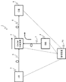
- FIG. 1 is a block diagram illustrating a configuration of an optical transmission system according to the first embodiment.
- an optical transmission system 1 includes an OADM branching device 2, an A station terminal device 3, a B station terminal device 4, a C station device 5, optical transmission lines 6, 7, 8 is provided.
- the terminal devices 3, 4, and 5 are connected to the OADM branching device 2 through optical transmission lines 6, 7, and 8, respectively.
- each of the terminal station devices 3, 4, and 5 includes an optical transmission device 10 and an optical reception device 20.
- FIG. 2 is a block diagram illustrating a configuration of the optical transmission device 10.
- the optical transmitter 10 includes optical transmitters T1 to Tn (n is an integer equal to or greater than 1), a first optical multiplexer 11, a dummy light generator 12, and a second optical multiplexer 13. Is provided.
- Each of the optical transmitters T1 to Tn outputs an optical signal having a predetermined wavelength.
- the first optical multiplexer 11 multiplexes the optical signals from the optical transmitters T1 to Tn to generate a WDM optical signal.
- the dummy light generator 12 generates dummy light for stabilizing the gain characteristics of an optical amplifying repeater (not shown) in the optical transmission system 1.
- An ASE (Amplified Spontaneous Emission) dummy light based on spontaneous emission light noise generated by an erbium-doped fiber amplifier (EDFA: Erbium Doped optical Fiber Amplifier) is generated, and the ASE dummy light is shaped by a wavelength filter to generate dummy light. Is done.
- the dummy light generation unit 12 generates, for example, dummy light having an optical spectrum having a comb shape and an equal interval (wavelength interval ⁇ ). Here, the wavelength of the generated dummy light is shifted so that the wavelength arrangement of the dummy light is different for each terminal station.
- the method of generating dummy light having a different wavelength arrangement for each terminal station is not limited to shifting the wavelength.
- the dummy light generation unit 12 makes the central wavelength position of the rectangular light spectrum constituting the dummy light different for each terminal station, makes the rectangular light spectrum width of the dummy light different for each terminal station,
- the dummy light may be generated so that the wavelength interval of the dummy light is different for each terminal station (for example, ⁇ 1 and ⁇ 2).
- the dummy light can also be generated as a dummy light based on continuous (CW: Continuous Wave) light generated by a laser diode (LD).
- CW Continuous Wave
- the configuration in FIG. 1 is an example applied to an optical transmission system in which three terminal stations are connected to an OADM branching device, but there are four or more terminal stations by providing a plurality of OADM branching devices.
- the present invention can also be applied to an optical transmission system. In the case of an optical transmission system having four or more terminal stations, it is not necessary to change the wavelength arrangement of the dummy light in each of the four or more terminal stations. When the terminal station receives and monitors the WDM optical signal, it is only necessary that the wavelength arrangement changes between adjacent subbands.
- the received light of the terminal station is composed of wavelength bands of subband AD, subband BD, and subband CD.
- the wavelength arrangement of the dummy light is different between the subbands AD and BD and between the subbands BD and CD, the subbands AD and subbands Even when the wavelength arrangement of the dummy light between CD is the same, the OADM filter boundary can be identified. In this way, the dummy light of the terminal station is generated so that the wavelength arrangement of the dummy light differs between the terminal stations that transmit the optical signals of the adjacent subbands among the WDM optical signals received by the terminal station.
- the OADM branching device 2 has an OADM function for inserting or branching an optical signal in units of wavelengths, and the WDM optical signals respectively output from the terminal station device 3 of the station A and the terminal station device 4 of the station B, Insert or branch by wavelength band.
- the filter boundary to be inserted or branched in wavelength band units is ⁇ F unless otherwise specified.
- FIG. 3 is a block diagram showing a configuration of the optical receiver 20.
- the optical receiver 20 includes a first optical demultiplexer 21, a second optical demultiplexer 22, an optical spectrum monitor unit 23, a monitoring unit 24, and optical receivers R1 to Rm (m is 1 or more). Integer).
- the first optical demultiplexer 21 demultiplexes the WDM optical signal output from the OADM branching device 2.
- One of the demultiplexed WDM optical signals is output to the second optical demultiplexer 22, and the other is output to the optical spectrum monitor unit 23.
- the second optical demultiplexer 22 demultiplexes the input WDM optical signal for each predetermined wavelength, and the optical receivers R1 to Rm receive the optical signals having the demultiplexed wavelengths.
- the optical spectrum monitor unit 23 measures the output optical spectrum of the WDM optical signal demultiplexed by the first optical demultiplexer 21, and the monitoring unit 24 analyzes the measurement result of the optical spectrum monitor unit 23.
- the monitoring unit 24 can filter the filter boundary of the OADM branching device at the terminal station. Can be specified. This is because the shape of the optical spectrum of the dummy light is different between the filter boundary of the OADM branching apparatus and the other because the wavelength arrangement of the dummy light is different for each terminal station.
- FIG. 4 is a conceptual diagram showing the state of the optical spectrum in the optical transmission system 1.
- the terminal station device 3 of the A station transmits an optical signal in the wavelength band “AB” communicated between the A station and the B station, and an optical signal in the wavelength band “AC” communicated between the A station and the C station. (FIG. 4A).
- the terminal device 4 of the B station includes an optical signal in the wavelength band “BC” communicated between the B station and the C station, and a dummy light for stabilizing the optical amplifying repeater included in the optical transmission line ( Hereinafter, DL (shown as Dummy Light) is transmitted as necessary ((b) of FIG. 4).
- DL shown as Dummy Light
- the OADM branching device 2 passes only the optical signal in the wavelength band “AC” assigned between the A station and the C station among the optical signals from the terminal device 3 of the A station by the filter of the OADM function ( (C) of FIG.
- the OADM branching device 2 passes only the optical signal in the wavelength band “BC” assigned between the B station and the C station among the optical signals from the B station ((d) in FIG. 4).
- the OADM branching device 2 combines and outputs the respective optical signals that have passed through the filter.
- the terminal device 5 of the C station receives the optical signals in the wavelength band “AC” and the wavelength band “BC” ((e) in FIG. 4).
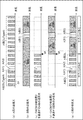
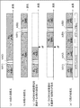
- FIG. 5 is a conceptual diagram showing a state of an optical spectrum of an optical transmission system using dummy lights having different wavelength arrangements at each terminal station.
- the dummy lights from the terminal stations A and B have a comb-shaped wavelength arrangement with equal wavelength intervals ( ⁇ ), and the dummy lights are transmitted at the terminal stations A and B. This will be described using an example in which the wavelength arrangement is shifted.
- the terminal station device 3 of the A station of the optical transmission system 1 performs optical signals of ⁇ (A1) and ⁇ (A2) in the wavelength band “AC” for communication between the A station and the C station.
- a station DL (Type 1) is multiplexed and transmitted as dummy light ((a) of FIG. 5).
- the A station DL (Type 1) has a wavelength arrangement that becomes a dummy light having a comb shape and an equal wavelength interval ( ⁇ ).
- the terminal device 4 of the B station transmits the optical signals of ⁇ (B1) and ⁇ (B2) in the wavelength band “BC” ⁇ ⁇ communicated between the B station and the C station, and the B station DL (Type 2) as dummy light. Are combined and transmitted.
- the DL (Type 2) of the B station has a wavelength arrangement that becomes a dummy light having a comb-like shape and an equal wavelength interval ( ⁇ ). Note that the wavelength arrangement of the DL (Type 2) of the B station and the wavelength arrangement of the DL (Type 1) of the A station are shifted ((b) in FIG. 5).
- the OADM branching device 2 passes only the optical signal in the wavelength band “AC” assigned between the A station and the C station among the optical signals from the terminal device 3 of the A station by the filter of the OADM function ( (C) of FIG.
- the OADM branching device 2 passes only the optical signal in the wavelength band “BC” assigned between the B station and the C station among the optical signals from the B station ((d) in FIG. 5).
- the OADM branching device 2 combines and outputs the respective optical signals that have passed through the filter.
- the terminal device 5 of the C station receives the optical signals of the wavelength band “AC” and the wavelength band “BC” ((e) of FIG. 5).
- the terminal device 5 of the C station measures the optical spectrum of the received light by the optical spectrum monitor unit 23, and the monitoring unit 24 has a region where the wavelength arrangement of the dummy light differs from the equal wavelength interval ( ⁇ ) by analysis. Then, the wavelength position can be specified. Thereby, the terminal device 5 of the C station can specify the wavelength of the filter boundary of the OADM branching device 2.
- FIG. 6 is a block diagram showing a configuration of an optical transmission system including two OADM branching devices.
- the optical transmission system 40 includes a first OADM branch device 41, a second OADM branch device 42, a terminal station device 43 of station A, a terminal device 44 of station B, a terminal device 45 of station C, D A terminal device 46 of the station and optical transmission lines 47, 48, 49, 50, 51 are provided.
- the terminal station devices 43 and 44 are connected to the first OADM branching device 41 via optical transmission paths 47 and 48, respectively.
- the terminal station devices 45 and 46 are connected to the second OADM branching device 42 via optical transmission paths 50 and 51, respectively.
- the first OADM branch device 41 and the second OADM branch device 42 are connected via an optical transmission line 49.
- the terminal device 43, 44, 45, 46 includes the optical transmitter 10 and the optical receiver 20, respectively.
- the WDM wavelength band needs to distinguish transmission signals from the three stations.
- the wavelength arrangement of the transmitted light in the terminal station device 43 of the A station, the terminal device 44 of the B station, and the terminal device 45 of the C station, and the wavelength of the received light of the D station An example of arrangement will be described.
- the terminal device 43 of the A station includes an optical signal in the wavelength band “AD” communicated between the A station and the D station, an optical signal in the wavelength band “AB” communicated between the A station and the B station, and A The optical signals in the wavelength band “AC” for communication between the station C and the station C are multiplexed and transmitted ((a) in FIG. 7).
- the terminal device 44 of the B station multiplexes and transmits the optical signal of the wavelength band “BD” communicated between the B station and the D station and the two dummy lights (DL) (( b)).
- the first OADM branching device 41 includes an optical signal of the wavelength band “AD” assigned between the A station and the D station among the optical signals from the terminal station device 43 of the A station by the filter of the OADM function, and A Only the optical signal in the wavelength band “AC” assigned between the station C and the station C is allowed to pass ((c) in FIG. 7).
- the first OADM branching device 41 passes only the optical signal in the wavelength band “BD” assigned between the B station and the D station among the optical signals from the terminal device 44 of the B station (FIG. 7). (D)).
- the first OADM branching device 41 combines the optical signals after passing through the filters, and outputs optical signals in the wavelength band “AD”, the wavelength band “AC”, and the wavelength band “BD” (FIG. 7 (e)).
- the terminal device 45 of the C station multiplexes and transmits the optical signal in the wavelength band “CD” and the dummy light (DL) for communication between the C station and the D station ((f) in FIG. 8). ).
- the second OADM branching device 42 is an optical signal of the wavelength band “AD” assigned between the A station and the D station and the B station and the D station among the optical signals from the first OADM branching device 41 by the filter of the OADM function. Only optical signals in the wavelength band “BD” assigned in between are allowed to pass ((g) in FIG. 8).
- the second OADM branching device 42 uses only the optical signal in the wavelength band “CD” assigned between the C station and the D station among the optical signals from the terminal station device 45 of the C station by the filter of the OADM function. Pass through ((h) in FIG. 8). As a result, the terminal device 45 of the D station receives the optical signals in the wavelength band “AD”, the wavelength band “BD”, and the wavelength band “CD” ((i) in FIG. 8).
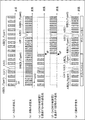
- FIG. 9 is a conceptual diagram showing a state of an optical spectrum of an optical transmission system using dummy lights having different wavelength arrangements at each terminal station.
- the dummy light from the terminal station has a comb-like shape and a wavelength arrangement of equal wavelength intervals ( ⁇ 2 ), and the wavelength of the dummy light between the terminal stations A, B, and C This will be described using an example in which the arrangement is shifted.
- the terminal station device 43 of the A station of the optical transmission system 1 performs optical signals of ⁇ (A1) and ⁇ (A2) in the wavelength band “AD” for communication between the A station and the D station.
- a station DL (Type 3) is multiplexed and transmitted as dummy light ((a) of FIG. 9).
- the A station DL (Type 3) has a comb-like shape and a wavelength arrangement that becomes dummy light with equal wavelength intervals ( ⁇ 2 ).
- the terminal device 44 of the B station includes optical signals of ⁇ (B1) and ⁇ (B2) in the wavelength band “BD” for communication between the B station and the C station, and a B station DL (Type 4) as dummy light. Are combined and transmitted.
- the B station DL (Type 4) has a comb-like shape and a wavelength arrangement that becomes dummy light with an equal wavelength interval ( ⁇ 2 ) ((b) of FIG. 9).
- the terminal device 45 of the C station combines the optical signal of ⁇ (C1) in the wavelength band “CD” communicated between the C station and the D station and the C station DL (Type 5) as dummy light.
- the C station DL (Type 5) has a comb-like shape and a wavelength arrangement that becomes dummy light with an equal wavelength interval ( ⁇ 2 ).
- Each of the A station DL (Type 3), the B station DL (Type 4), and the C station DL (Type 5) does not overlap the wavelength arrangement of the dummy light.
- the transmission light from the A station, the B station, and the C station is transmitted to the D station via the first OADM branch device 41 and the second OADM branch device 42.
- the terminal device 46 of the D station receives the optical signals in the wavelength band “AD”, the wavelength band “BD”, and the wavelength band “CD” ((d) in FIG. 9).
- the terminal station device 46 of the D station measures the optical spectrum of the received light by the optical spectrum monitor unit 23.
- the monitoring unit 24 has two regions where the wavelength arrangement of the dummy light differs from the equal wavelength interval ( ⁇ 2 ) by analysis, and can identify the wavelength position. Thereby, the terminal station device 46 of the D station can specify the wavelength ⁇ Fab of the filter boundary of the first OADM branch device 41 and the wavelength ⁇ Fbc of the filter boundary of the second OADM branch device 42.
- the filter boundary of the OADM branching device can be specified at the station.
- the dummy light of the transmission light from the terminal device 4 of the B station is not a comb shape (discrete rectangular shape) but a flat shape ( The difference is that the shape is continuous.
- This example can be regarded as a wavelength arrangement in which the optical spectrum width of the dummy light is different between the A station and the B station.
- the terminal station device 3 of the A station of the optical transmission system 1 transmits optical signals of ⁇ (A1) and ⁇ (A2) in the wavelength band “AC” for communication between the A station and the C station.
- a station DL (Type1) is multiplexed and transmitted as dummy light ((a) of FIG. 10).
- the A station DL (Type 1) has a wavelength arrangement that becomes a dummy light having a comb shape and an equal wavelength interval ( ⁇ ).
- the terminal device 4 of the B station multiplexes the optical signals of ⁇ (B1) and ⁇ (B2) in the wavelength band “BC” ⁇ ⁇ for communication between the B station and the C station, and the B station DL as dummy light. Then send.
- the B station DL has a flat optical spectrum shape, and has a wavelength arrangement that is different from the A station DL (Type 1) in the optical spectrum width ((b) in FIG. 10).
- the OADM branching device 2 passes only the optical signal in the wavelength band “AC” assigned between the A station and the C station among the optical signals from the terminal device 3 of the A station by the filter of the OADM function ( (C) of FIG.
- the OADM branching device 2 passes only the optical signal in the wavelength band “BC” assigned between the B station and the C station among the optical signals from the B station ((d) in FIG. 10).
- the OADM branching device 2 combines and outputs the respective optical signals that have passed through the filter.
- the terminal device 45 of the C station receives the optical signals in the wavelength band “AC” and the wavelength band “BC” ((e) in FIG. 10).
- the terminal device 5 of the C station measures the optical spectrum of the received light by the optical spectrum monitor unit 23, and the monitoring unit 24 has a region where the wavelength position of the dummy light is different from the equal wavelength interval ( ⁇ ) by analysis. Then, the wavelength position can be specified. Thereby, the terminal device 5 of the C station can specify the wavelength of the filter boundary of the OADM branching device 2.
- the filter boundary of the OADM branching device can be specified at the station.
- the terminal device 3 of the A station transmits dummy light having a comb-shaped shape and an equal wavelength interval ( ⁇ ), and the terminal device 4 of the B station has a comb-shaped shape and an equal wavelength interval ( ⁇ / 2)
- dummy light whose optical spectrum width is 1 ⁇ 2 of the dummy light of station A is transmitted.
- This example is an example of a wavelength arrangement in which the equal wavelength interval of the dummy light is different between the A station and the B station, and the optical spectrum width of the dummy light is different.
- the terminal station device 3 of the A station of the optical transmission system 1 transmits optical signals of ⁇ (A1) and ⁇ (A2) in the wavelength band “AC” for communication between the A station and the C station.
- a station DL (Type 1) is multiplexed and transmitted as dummy light ((a) of FIG. 11).
- the A station DL (Type 1) has a wavelength arrangement of equal wavelength intervals ( ⁇ ).
- the terminal device 4 of the B station transmits the optical signals of ⁇ (B1) and ⁇ (B2) in the wavelength band “BC” ⁇ communicated between the B station and the C station, and the B station DL (Type 6) as dummy light. Are combined and transmitted.
- the B station DL (Type 6) has an equal wavelength interval ( ⁇ / 2), and further has a wavelength arrangement in which the optical spectrum width is 1 ⁇ 2 of the A station DL (Type 1) ((b) of FIG. 11).
- the OADM branching device 2 passes only the optical signal in the wavelength band “AC” assigned between the A station and the C station among the optical signals from the terminal device 3 of the A station by the filter of the OADM function ( (C) of FIG.
- the OADM branching apparatus 2 passes only the optical signal in the wavelength band “BC” assigned between the B station and the C station among the optical signals from the B station ((d) in FIG. 11).
- the OADM branching device 2 combines and outputs the respective optical signals that have passed through the filter.
- the terminal device 45 of the C station receives the optical signals of the wavelength band “AC” and the wavelength band “BC” ((e) of FIG. 11).
- the terminal device 5 of the C station measures and analyzes the optical spectrum of the received light by the optical spectrum monitor unit 23 and the monitoring unit 24. Since the wavelength arrangement of the dummy light is different between the A station and the B station, the monitoring unit 24 identifies areas where the equal wavelength intervals ( ⁇ and ⁇ / 2) of the dummy light are different or areas where the optical spectrum widths are different. The boundary can be specified. Thereby, the terminal device 5 of the C station can specify the wavelength of the filter boundary of the OADM branching device 2.
- the filter boundary of the OADM branching device can be specified at the station.
- the fifth embodiment is an example in which dummy light arranged at equal wavelength intervals is applied to the configuration of the optical transmission system of the second embodiment.
- FIG. 12 is a conceptual diagram showing a state of an optical spectrum of an optical transmission system using dummy lights having different wavelength arrangements at each terminal station.
- the dummy light from the terminal station has a wavelength arrangement of equal wavelength interval ([Delta] [lambda] 3), and an equal wavelength interval of the dummy light among the three terminal stations ([Delta] [lambda] 3 ) Is an example in which the wavelength arrangement of the dummy light is shifted so as not to overlap.
- the end station device 43 of the A station of the optical transmission system 1 transmits optical signals of ⁇ (A1) and ⁇ (A2) in the wavelength band “AD” for communication between the A station and the D station.
- a station DL (Type 7) is multiplexed and transmitted as dummy light ((a) of FIG. 12).
- the A station DL (Type 7) has a wavelength arrangement that becomes dummy light at equal wavelength intervals ( ⁇ 3 ).
- the terminal device 44 of the B station includes optical signals of ⁇ (B1) and ⁇ (B2) in the wavelength band “BD” for communication between the B station and the C station, and the B station DL (Type 8) as dummy light. Are combined and transmitted.
- the DL (Type 8) of the B station has a wavelength arrangement that becomes dummy light with an equal wavelength interval ( ⁇ 3 ) ((b) of FIG. 12).
- the terminal device 45 of the C station combines the optical signal of ⁇ (C1) in the wavelength band “CD” for communication between the C station and the D station and the C station DL (Type 9) as dummy light.
- the DL (Type 9) of the C station has a wavelength arrangement that becomes dummy light at equal wavelength intervals ( ⁇ 3 ) ((C) in FIG. 12). Further, the wavelength arrangement among the A station DL (Type 7), the B station DL (Type 8), and the C station DL (Type 9) is shifted so that the equal wavelength intervals do not overlap each other.
- the transmission light from the A station, the B station, and the C station is transmitted to the D station via the first OADM branching device 41 or the second OADM branching device 42.
- the terminal device 46 of the D station receives the optical signals in the wavelength band “AD”, the wavelength band “BD”, and the wavelength band “CD” ((d) in FIG. 12).
- the terminal station device 46 of the D station measures the optical spectrum of the received light by the optical spectrum monitor unit 23.
- the monitoring unit 24 can identify that there is a region where the equal wavelength interval ( ⁇ 3 ) of the dummy light is different depending on the wavelength arrangement of the dummy light from each terminal station, and can specify the wavelength position.
- the terminal device 46 of the D station can specify the wavelength ⁇ Fab of the filter boundary of the first OADM branch device 41 and the wavelength ⁇ Fbc of the filter boundary of the second OADM branch device 42.
- the filter boundary of the OADM branching device can be specified at the station.
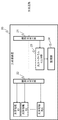
- FIG. 13 is a block diagram illustrating a configuration of an optical transmission system including the management device 70.
- the management device 70 is connected to each of the terminal devices 3, 4, and 5 of the terminal station and transmits wavelength information of dummy light between the terminal stations or wavelength in the subband to the terminal device that transmits the transmission light. A function of transmitting arrangement information is provided.
- the management device is connected to the OADM branch device 2 and controls switching of the ADD / DROP signal from the OADM branch device 2.
- the management device 70 adjusts the wavelength arrangement of the dummy light generated by the terminal station devices 3, 4, and 5 to be different between the terminal stations, and assigns the wavelength arrangement information of the dummy light to the terminal station devices 3, 4, 5, or Wavelength allocation information in the subband is transmitted.
- the management apparatus adjusts the wavelength arrangement of the dummy light for each terminal station, thereby facilitating management of the operation state of the optical transmission system.
- the management device has a monitoring unit, and obtains information obtained by monitoring the optical spectrum of the WMD optical signal from the terminal device that has received the WDM optical signal including the dummy light, and specifies the wavelength of the filter boundary of the OAM branching device. May be.
- FIG. 14 is a diagram illustrating a hardware configuration in which the management device 70 is realized by a computer device.
- a management device 70 As shown in FIG. 14, a management device 70, a CPU (Central Processing Unit) 91, a communication I / F (communication interface) 92 for network connection, a memory 93, and a storage device 94 such as a hard disk for storing programs are included. .
- the management device 70 is connected to the input device 95 and the output device 96 via the system bus 97.
- the CPU 91 operates the operating system to control the management device in the embodiment of the present invention. Further, the CPU 91 reads out programs and data from the recording medium mounted on the drive device to the memory 93, for example.
- the CPU 91 has a function of processing an input information signal, for example, and executes various functions based on a program.
- the storage device 94 is, for example, an optical disk, a flexible disk, a magnetic optical disk, an external hard disk, or a semiconductor memory.
- a part of the storage medium of the storage device 94 is a nonvolatile storage device, and stores a program therein.
- the program is connected to a communication network. It may be downloaded from an external computer (not shown).
- the input device 95 is realized by, for example, a mouse, a keyboard, a built-in key button, a card slot, or a touch panel, and is used for an input operation.
- the output device 96 is realized by a display, for example, and is used for outputting and confirming information processed by the CPU 91.
- the dummy wavelength arrangement included in the transmission light from the terminal station is different for each terminal station.
- Wavelength allocation information (equal wavelength interval, rectangular center wavelength interval or optical spectrum width, etc.) of dummy light at each terminal station is obtained in advance from the other station or network management device, and the optical spectrum of the received dummy light is received. It is possible to identify which terminal station is the dummy light transmitted. Therefore, it is possible to confirm whether or not the OADM branching apparatus is correctly switched at the receiving terminal station side.
- OADM branching device in each of the above embodiments, a ROADM (Reconfigurable Optical Add / Drop Multiplexer) branching device can be used.
- ROADM Reconfigurable Optical Add / Drop Multiplexer
- the optical signal / noise ratio (OSNR) monitoring function is provided by combining the optical signal with a waveform similar to that of the optical signal. You can also.
- OSNR optical signal / noise ratio
- the direction of the arrow in the drawing shows an example, and does not limit the direction of the signal between the blocks.
- a terminal device for outputting a wavelength multiplexed optical signal obtained by combining the optical signal and the dummy light;
- An OADM branching device for inputting and dropping the wavelength multiplexed optical signals output from the plurality of terminal devices, respectively,
- the dummy light has a wavelength arrangement in which adjacent wavelength intervals are arranged at equal intervals, and the wavelength arrangement of the dummy light is different for each terminal device.
- Appendix 4 The optical transmission system according to appendix 1, wherein an optical spectrum width of the dummy light is different for each terminal device.
- one of the terminal devices has a wavelength arrangement in which the dummy lights are equi-wavelength intervals, and the other terminal device has an optical spectrum shape in which the dummy lights are continuous.
- a receiving side terminal device for receiving the output light from the OADM branching device;
- the reception-side terminal device has monitoring means for analyzing an optical spectrum of the output light,
- the optical transmission system according to any one of appendices 1 to 5.
- a terminal device of an optical transmission system including an OADM branching device that performs add / drop processing by inputting a wavelength multiplexed optical signal obtained by combining an optical signal and dummy light from a plurality of terminal devices,
- the dummy light has a wavelength arrangement in which adjacent wavelength intervals are arranged at equal intervals, and the wavelength arrangement of the dummy light is different for each terminal device.
- a receiving-side terminal device of an optical transmission system including an OADM branching device that inputs wavelength multiplexed optical signals from a plurality of terminal devices, The input to the OADM branching device is a wavelength division multiplexed optical signal obtained by combining a dummy light and an optical signal having different wavelength arrangements for each terminal device,
- Optical spectrum monitoring means for measuring the optical spectrum of the output light output from the OADM branching device; Monitoring means for identifying a filter boundary of the OADM branching device in the measured optical spectrum based on a difference in wavelength arrangement of the dummy light for each terminal device reflected in the optical spectrum;
- a receiving side terminal device A receiving side terminal device.
- An analysis method of an optical transmission system including an OADM branching device connected to a terminal device, Wavelength multiplexed optical signals obtained by combining dummy light and optical signals having different wavelength arrangements for each terminal device are added / drop processed by the OADM branching device, and output.
- the optical spectrum of the output light output from the OADM branching device is measured, and the filter of the OADM branching device in the optical spectrum is based on the difference in wavelength arrangement of the dummy light for each terminal device reflected in the optical spectrum.
- Appendix 10 An optical transmission system management device according to any one of appendices 1 to 6, Connected to the terminal device, A management device for an optical transmission system, which transmits to the terminal device wavelength arrangement information in which the wavelength arrangement of the dummy light is different for each terminal device.
Landscapes
- Engineering & Computer Science (AREA)
- Computer Networks & Wireless Communication (AREA)
- Signal Processing (AREA)
- Physics & Mathematics (AREA)
- Electromagnetism (AREA)
- Optical Communication System (AREA)
Abstract
光伝送システムの波長帯域内でダミー光の波長帯の占める割合が、主たる光信号の波長帯の占める割合よりも多い場合であっても、端局において光分岐挿入装置のフィルタ境界を特定することを可能にする。光伝送システムは、光信号とダミー光を合波した波長多重光信号を出力する端局装置と、複数の前記端局装置から出力された前記波長多重光信号をそれぞれ入力してadd/drop処理する光分岐挿入装置と、を備え、前記ダミー光は、隣接する波長間隔が等間隔に配置された波長配置であり、前記端局装置ごとに前記ダミー光の波長配置が異なる。
Description
本発明は、光分岐挿入装置を含む光伝送システムに関する。
近年、光ファイバを使う光伝送システムにおける接続性の向上、あるいは、運用面の利便性が求められる中、同一ファイバ伝送路上で波長単位又は波長帯単位での光信号のOADM(Optical Add/Drop Multiplexer)機能、可変波長機能を提供する光伝送システムが注目されている。特に、波長選択スイッチ(WSS:Wavelength Selective Switch)技術の導入による分解能の向上によって光分岐挿入装置(以降、OADM分岐装置と示す)を適用する光伝送システムは、更なる利便性、又は接続性が進んでいる。
一方で、波長多重技術やOADM機能の導入により、局数の増加とともに波長帯単位での接続管理などシステム構成が複雑化しており、障害又は設定変更の対応のために光伝送システムの運用状態を監視する機能の提供が必要不可欠となっている。
特許文献1には、端局装置に波長ブロック単位の信号断を検出する信号断検出部を備え、信号断が検出された端局装置のダミー光の強度を調節する制御信号を送信する光信号レベル調整システムが記載されている。
ところで、OADM分岐装置を含む光伝送システムの初期運用状態において、光伝送路を伝搬するWDM(Wavelength Division Multiplex)光信号の中で、ダミー光の波長数(波長帯)の占める割合が、主信号の波長数(波長帯)の占める割合よりも多くなる。
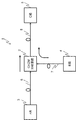
図15は、OADM分岐装置を含む光伝送システムの概要図である。図15に示すように、光伝送システム81は、OADM分岐装置82と、A局83、B局84、C局85、光伝送路86、87、88を備える。図16は、図15に示す光伝送システム81の初期運用時における光スペクトラムの状態を示す概要図である。初期運用時の光伝送システム81において、A局83の送信光は、A局83とC局85間で通信するλ(A1)とλ(A2)の2波長分の光信号を配置し、残りの帯域にダミー光を配置して出力する(図16の(a))。またB局84の送信光は、B局84とC局85間で通信するλ(B1)とλ(B2)の2波長分の光信号を配置し、残りの帯域にダミー光を配置して出力する(図16の(b))。
OADM分岐装置82は、A局83の送信光の内、λ(A1)、λ(A2)を含む、フィルタ境界の波長λFより低い帯域の波長を通過し(図16の(c))、B局84の送信光の内、λFより高い帯域の波長を通過する(図16の(d))。更に通過したA局83の送信光、B局84の送信光がOADM分岐装置82で合波されてC局85へ出力される。結果、C局85の受信光の光スペクトラムの状態は、フィルタ境界の波長λF周辺にはA局83のダミー光、B局84のダミー光が配置されることになる。このため、C局85の受信光でOADM分岐装置82のフィルタ境界を特定することが困難となる。
このように、光伝送システムの波長帯域内で、ダミー光の波長帯の占める割合が、主たる光信号の波長帯の占める割合よりも多い場合、端局で受信したWDM光信号をモニタしてもOADM分岐装置のフィルタ境界の特定が困難となる。このためOADM分岐装置の光透過状態、及び、光伝送システムに割当てられている波長配置を検出することができなくなる。
本発明の目的は、光伝送システムの波長帯域内でダミー光の波長帯の占める割合が、主たる光信号の波長帯の占める割合よりも多い場合であっても、端局においてOADM分岐装置のフィルタ境界を特定することを可能にする技術を提供することにある。
本発明の一形態である光伝送システムは、光信号とダミー光を合波した波長多重光信号を出力する端局装置と、複数の前記端局装置から出力された前記波長多重光信号をそれぞれ入力してadd/drop処理する光分岐挿入装置と、を備え、前記ダミー光は、隣接する波長間隔が等間隔に配置された波長配置であり、前記端局装置ごとに前記ダミー光の波長配置が異なる。
本発明の一形態である端局装置は、光信号とダミー光を合波した波長多重光信号を複数の端局装置からそれぞれ入力してadd/drop処理する光分岐挿入装置を含む光伝送システムの端局装置であって、前記ダミー光は、隣接する波長間隔が等間隔に配置された波長配置であり、前記端局装置ごとに前記ダミー光の波長配置が異なる。
本発明の一形態である受信側端局装置は、複数の端局装置からの波長多重光信号をそれぞれ入力する光分岐挿入装置を含む光伝送システムの受信側端局装置であって、前記光分岐挿入装置への入力が、前記端局装置ごとに波長配置が異なるダミー光および光信号が合波された波長多重光信号であり、前記前記光分岐挿入装置から出力された出力光の光スペクトラムを測定する光スペクトラムモニタ手段と、前記光スペクトラムに反映された前記端局装置ごとの前記ダミー光の波長配置の差異に基づいて、前記測定した光スペクトラムにおける前記光分岐挿入装置のフィルタ境界を識別する監視手段と、を備える。
本発明の一形態である解析方法は、端局装置に接続された光分岐挿入装置を含む光伝送システムの解析方法であって、前記端局装置ごとに波長配置が異なるダミー光および光信号が合波された波長多重光信号を前記光分岐挿入装置でadd/drop処理して出力し、前記光分岐挿入装置が出力した出力光の光スペクトラムを測定し、前記光スペクトラムに反映された前記端局装置ごとのダミー光の波長配置の差異に基づいて、前記光スペクトラムにおける前記光分岐挿入装置のフィルタ境界を識別する。
本発明の一形態である光伝送システムの管理装置は、上記の光伝送システムの管理装置であって、前記端局装置に接続され、前記端局装置ごとに前記ダミー光の前記波長の配置が異なるように調整された波長の配置情報を前記端局装置に送信する。
本発明は、光伝送システムの波長帯域内でダミー光の波長帯の占める割合が、主たる光信号の波長帯の占める割合よりも多い場合であっても、端局において光分岐挿入装置のフィルタ境界を特定することを可能にする。
(第1の実施形態)
はじめに、本発明の第1の実施形態における光伝送システムについて、図面を用いて説明する。図1は、第1の実施形態における光伝送システムの構成を示すブロック図である。
はじめに、本発明の第1の実施形態における光伝送システムについて、図面を用いて説明する。図1は、第1の実施形態における光伝送システムの構成を示すブロック図である。
図1に示すように、光伝送システム1は、OADM分岐装置2と、A局の端局装置3、B局の端局装置4、C局の端局装置5、光伝送路6、7、8を備える。端局装置3、4、5は、それぞれ光伝送路6、7、8を介してOADM分岐装置2に接続される。また、端局装置3、4、5は、それぞれ光送信装置10および光受信装置20を備える。
光送信装置10について説明する。図2は、光送信装置10の構成を示すブロック図である。図2に示すように、光送信装置10は、光送信機T1~Tn(nは1以上の整数)と、第1光合波器11と、ダミー光発生部12と、第2光合波器13を備える。光送信機T1~Tnは、それぞれ所定波長の光信号を出力する。第1光合波器11は、光送信機T1~Tnからの光信号を多重化してWDM光信号を生成する。
ダミー光発生部12は、光伝送システム1内の光増幅中継器(図示せず)の利得特性を安定化させるためのダミー光を生成する。エルビウムドープトファイバー増幅器(EDFA:Erbium Doped optical Fiber Amplifier)による自然放出光雑音をベースにしたASE(Amplified Spontaneous Emission)ダミー光を発生させ、このASEダミー光を波長フィルタにより整形してダミー光が生成される。ダミー光発生部12は、例えば、櫛型形状で等間隔(波長間隔Δλ)となる光スペクトルのダミー光を生成する。ここで、生成されるダミー光は、端局ごとにダミー光の波長配置が異なるように波長がシフトされる。
端局ごとに波長配置の異なるダミー光を生成する方法は、波長をシフトすることに限定されない。例えば、ダミー光発生部12は、端局ごとにダミー光を構成する矩形の光スペクトルの中心波長位置が異なるようにする、端局ごとにダミー光の矩形の光スペクトル幅が異なるようにする、あるいは、端局ごとにダミー光の波長間隔が異なる(例えば、Δλ1とΔλ2)ようにダミー光を発生させてもよい。
また、ダミー光は、EDFAによるASE光をベースにする以外に、レーザダイオード(LD:Laser Diode)による連続(CW:Continuous Wave)光をベースにしてダミー光で生成することもできる。
なお、上記図1の構成は、3つの端局がOADM分岐装置に接続される光伝送システムに適用する例であるが、OADM分岐装置を複数設けることで、4つ以上の端局が存在する光伝送システムにも適用することができる。4つ以上の端局が存在する光伝送システムの場合、4つ以上の端局のそれぞれにおいてダミー光の波長配置を変える必要はない。端局でWDM光信号を受信しモニタする際に、隣接するサブバンドとの間で波長配置が変わっていればよい。
例えば、端局の受信光がサブバンドA-D、サブバンドB-D、サブバンドC-Dの波長帯域で構成されているとする。このとき、サブバンドA-DとサブバンドB-D間、並びにサブバンドB-DとサブバンドC-D間におけるダミー光の波長の配置が異なっていれば、サブバンドA-DとサブバンドC-D間のダミー光の波長の配置が同じでもOADMのフィルタ境界を識別できる。このように、端局で受信するWDM光信号のうち隣接するサブバンドの光信号を送信する端局間におけるダミー光の波長配置が異なるように、端局のダミー光を生成する。
また、OADM分岐装置2は、波長単位で光信号を挿入又は分岐するOADM機能を備え、A局の端局装置3、及び、B局の端局装置4からそれぞれ出力されたWDM光信号を、波長帯域単位で挿入又は分岐する。このとき波長帯域単位で挿入又は分岐するフィルタ境界は、特に指定が無い限りλFとする。
次に、光受信装置20について説明する。図3は、光受信装置20の構成を示すブロック図である。図3に示すように、光受信装置20は、第1光分波器21、第2光分波器22、光スペクトラムモニタ部23、監視部24、光受信機R1~Rm(mは1以上の整数)を備える。
第1光分波器21は、OADM分岐装置2から出力されたWDM光信号を分波する。分波されたWDM光信号の一方は、第2光分波器22に出力され、他方は、光スペクトラムモニタ部23に出力される。
第2光分波器22は、入力したWDM光信号を所定の波長毎に分波し、光受信機R1~Rmは、分波された波長の光信号を受信する。光スペクトラムモニタ部23は、第1光分波器21で分波されたWDM光信号の出力光スペクトラムを測定し、監視部24は、光スペクトラムモニタ部23の測定結果を解析する。
光伝送システムの波長帯域内でダミー光の波長帯の占める割合が、主たる光信号の波長帯の占める割合よりも多い場合であっても、監視部24は、端局においてOADM分岐装置のフィルタ境界を特定することができる。これは、端局ごとにダミー光の波長配置が異なることによってOADM分岐装置のフィルタ境界とそれ以外で、ダミー光の光スペクトルの形状が異なるためである。
次に、第1の実施形態のOADM分岐装置を含む光伝送システムにおけるA局、B局の送信光の波長配置、及び、C局の受信光の波長配置の例について図面を用いて説明する。図4は、光伝送システム1における光スペクトラムの状態を示す概念図である。A局の端局装置3は、A局とB局間で通信する波長帯“A-B”の光信号及びA局とC局間で通信する波長帯“A-C”の光信号を送信する(図4の(a))。
B局の端局装置4は、B局とC局間で通信する波長帯“B-C”の光信号、及び、光伝送路に含まれる光増幅中継器を安定化させるためのダミー光(以下、必要に応じてDL(Dummy Light)と示す)を送信する(図4の(b))。
OADM分岐装置2は、OADM機能のフィルタによりA局の端局装置3からの光信号の内、A局とC局間にアサインされた波長帯”A-C”の光信号のみを通過させる(図4の(c))。また、OADM分岐装置2は、B局からの光信号の内、B局とC局間にアサインされた波長帯”B-C”の光信号のみを通過させる(図4の(d))。OADM分岐装置2は、フィルタ通過後したそれぞれの光信号を合波して出力する。この結果、C局の端局装置5は、波長帯”A-C”および波長帯”B-C”の光信号を受信する(図4の(e))。
次に、第1の実施形態における光伝送システムの動作について図面を用いて説明する。図5は、各端局で波長配置が異なるダミー光を用いた光伝送システムの光スペクトラムの状態を示す概念図である。第1の実施形態における光伝送システムにおいて、端局A、Bからのダミー光が、櫛型形状の等波長間隔(Δλ)の波長配置を有し、かつ、端局A、Bでダミー光の波長配置がシフトしている例を用いて説明する。
図5に示すように、光伝送システム1のA局の端局装置3は、A局とC局間で通信する波長帯“A-C”におけるλ(A1)、λ(A2)の光信号、及び、ダミー光としてA局DL(Type1)を合波して送信する(図5の(a))。A局DL(Type1)は、櫛型形状で等波長間隔(Δλ)のダミー光となる波長配置である。
B局の端局装置4は、B局とC局間で通信する波長帯“B-C” におけるλ(B1)、λ(B2)の光信号、及び、ダミー光としてB局DL(Type2)を合波して送信する。B局のDL(Type2)は、櫛型形状で等波長間隔(Δλ)のダミー光となる波長配置である。なお、B局のDL(Type2)の波長配置とA局のDL(Type1)の波長配置は波長シフトしている(図5の(b))。
OADM分岐装置2は、OADM機能のフィルタによりA局の端局装置3からの光信号の内、A局とC局間にアサインされた波長帯”A-C”の光信号のみを通過させる(図5の(c))。また、OADM分岐装置2は、B局からの光信号の内、B局とC局間にアサインされた波長帯”B-C”の光信号のみを通過させる(図5の(d))。OADM分岐装置2は、フィルタ通過後したそれぞれの光信号を合波して出力する。この結果、C局の端局装置5は、波長帯”A-C”および波長帯”B-C”の光信号を受信する(図5の(e))。
C局の端局装置5は、光スペクトラムモニタ部23により、受信光の光スペクトラムを測定し、監視部24は、解析によりダミー光の波長配置が、等波長間隔(Δλ)と異なる領域が存在し、その波長位置を特定することができる。これにより、C局の端局装置5は、OADM分岐装置2のフィルタ境界の波長を特定できる。
以上のように第1の実施形態によれば、光伝送システムの波長帯域内でダミー光の波長帯の占める割合が、主たる光信号の波長帯の占める割合よりも多い場合であっても、端局においてOADM分岐装置のフィルタ境界を特定することを可能にする。
(第2の実施形態)
第1の実施形態の光伝送システムでは、3つの端局装置が1つのOADM分岐装置に接続される例で説明したが、第2の実施形態では、1つの光伝送システム内にOADM分岐装置を備え、4つの端局装置が存在する例について説明する。
第1の実施形態の光伝送システムでは、3つの端局装置が1つのOADM分岐装置に接続される例で説明したが、第2の実施形態では、1つの光伝送システム内にOADM分岐装置を備え、4つの端局装置が存在する例について説明する。
図6は、2つのOADM分岐装置を含む光伝送システムの構成を示すブロック図である。図6に示すように、光伝送システム40は、第1OADM分岐装置41、第2OADM分岐装置42、A局の端局装置43、B局の端局装置44、C局の端局装置45、D局の端局装置46、光伝送路47、48、49、50、51を備える。端局装置43、44は、それぞれ光伝送路47、48を介して第1OADM分岐装置41に接続され、端局装置45、46は、それぞれ光伝送路50、51を介して第2OADM分岐装置42に接続される。また、第1OADM分岐装置41と第2OADM分岐装置42は光伝送路49を介して接続される。端局装置43、44、45、46は、それぞれ光送信装置10及び光受信装置20を備える。
第2の実施形態の光伝送システムのように4つの局が存在する場合、WDM波長帯は、3つの局からの送信信号を区別する必要がある。第2の実施形態の光伝送システム40におけるA局の端局装置43、B局の端局装置44、C局の端局装置45における送信光の波長配置、及び、D局の受信光の波長配置の例について説明する。
図7、図8は、第2の実施形態の光伝送システム40における光スペクトラムの状態を示す概念図である。
A局の端局装置43は、A局とD局間で通信する波長帯“A-D”の光信号、A局-B局間で通信する波長帯“A-B”の光信号及びA局とC局間で通信する波長帯“A-C”の光信号を合波して送信する(図7の(a))。
A局の端局装置43は、A局とD局間で通信する波長帯“A-D”の光信号、A局-B局間で通信する波長帯“A-B”の光信号及びA局とC局間で通信する波長帯“A-C”の光信号を合波して送信する(図7の(a))。
B局の端局装置44は、B局とD局間で通信する波長帯“B-D”の光信号、及び、2つのダミー光(DL)を合波して送信する(図7の(b))。
第1OADM分岐装置41は、OADM機能のフィルタによりA局の端局装置43からの光信号の内、A局とD局間にアサインされた波長帯“A-D”の光信号、及び、A局とC局間にアサインされた波長帯“A-C”の光信号のみを通過させる(図7の(c))。また、第1OADM分岐装置41は、B局の端局装置44からの光信号の内、B局とD局間にアサインされた波長帯“B-D”の光信号のみを通過させる(図7の(d))。第1OADM分岐装置41は、フィルタ通過後の光信号をそれぞれ合波し、波長帯”A-D”、波長帯”A-C”及び波長帯”B-D”の光信号を出力する(図7の(e))。
C局の端局装置45は、C局とD局間で通信する波長帯“C-D”の光信号、及び、ダミー光(DL)を合波して送信する(図8の(f))。
第2OADM分岐装置42は、OADM機能のフィルタにより第1OADM分岐装置41からの光信号の内、A局とD局間にアサインされた波長帯“A-D”の光信号及びB局とD局間にアサインされた波長帯“B-D”の光信号のみを通過させる(図8の(g))。
さらに、第2OADM分岐装置42は、OADM機能のフィルタによりC局の端局装置45からの光信号の内、C局とD局間にアサインされた波長帯“C-D”の光信号のみを通過させる(図8の(h))。この結果、D局の端局装置45は、波長帯”A-D”、波長帯”B-D”、波長帯”C-D”の光信号を受信する(図8の(i))。
次に、第2の実施形態における光伝送システムの動作について図面を用いて説明する。図9は、各端局で波長配置が異なるダミー光を用いた光伝送システムの光スペクトラムの状態を示す概念図である。第2の実施形態における光伝送システムについて、端局からのダミー光が、櫛型形状で等波長間隔(Δλ2)の波長配置を有し、端局A、B、C間でダミー光の波長配置がシフトしている例を用いて説明する。
図9に示すように、光伝送システム1のA局の端局装置43は、A局とD局間で通信する波長帯“A-D”におけるλ(A1)、λ(A2)の光信号、及び、ダミー光としてA局DL(Type3)を合波して送信する(図9の(a))。A局DL(Type3)は櫛型形状で等波長間隔(Δλ2)のダミー光となる波長配置である。
B局の端局装置44は、B局とC局間で通信する波長帯“B-D” におけるλ(B1)、λ(B2)の光信号、及び、ダミー光としてB局DL(Type4)を合波して送信する。B局DL(Type4)は、櫛型形状で等波長間隔(Δλ2)のダミー光となる波長配置である(図9の(b))。
C局の端局装置45は、C局とD局間で通信する波長帯“C-D” におけるλ(C1)の光信号、及び、ダミー光としてC局DL(Type5)を合波して送信する。C局DL(Type5)は、櫛型形状で等波長間隔(Δλ2)のダミー光となる波長配置である。
A局DL(Type3)、B局DL(Type4)、及び、C局DL(Type5)のそれぞれは、ダミー光の波長配置が重ならない。
A局、B局、C局からの送信光は、第1OADM分岐装置41、第2OADM分岐装置42を経てD局に送信される。D局の端局装置46は、波長帯”A-D”、波長帯”B-D”、波長帯”C-D”の光信号を受信する(図9の(d))。
D局の端局装置46は、光スペクトラムモニタ部23により、受信光の光スペクトラムを測定する。監視部24は、解析によりダミー光の波長配置が等波長間隔(Δλ2)と異なる領域が2箇所存在し、その波長位置を特定することができる。これにより、D局の端局装置46は、第1OADM分岐装置41のフィルタ境界の波長λFabと、第2OADM分岐装置42のフィルタ境界の波長λFbcを特定できる。
以上のように第2の実施形態によれば、光伝送システムの波長帯域内でダミー光の波長帯の占める割合が、主たる光信号の波長帯の占める割合よりも多い場合であっても、端局においてOADM分岐装置のフィルタ境界を特定することができる。
(第3の実施形態)
第3の実施形態は、第1の実施形態の光伝送システムのうち、B局の端局装置4からの送信光のダミー光が櫛型形状(離散的な矩形状)ではなく、フラット形状(連続した形状)となっている点が相違する。この例は、A局とB局間でダミー光の光スペクトル幅が異なる波長配置であると見ることができる。
第3の実施形態は、第1の実施形態の光伝送システムのうち、B局の端局装置4からの送信光のダミー光が櫛型形状(離散的な矩形状)ではなく、フラット形状(連続した形状)となっている点が相違する。この例は、A局とB局間でダミー光の光スペクトル幅が異なる波長配置であると見ることができる。
図10に示すように、光伝送システム1のA局の端局装置3は、A局とC局間で通信する波長帯“A-C”におけるλ(A1)、λ(A2)の光信号、及び、ダミー光としてA局DL(Type1)を合波して送信する(図10の(a))。A局DL(Type1)は、櫛型形状で等波長間隔(Δλ)のダミー光となる波長配置である。
B局の端局装置4は、B局とC局間で通信する波長帯“B-C” におけるλ(B1)、λ(B2)の光信号、及び、ダミー光としてB局DLを合波して送信する。B局DLは、フラットな光スペクトル形状であり、A局DL(Type1)と光スペクトル幅が異なる波長配置である(図10の(b))。
OADM分岐装置2は、OADM機能のフィルタによりA局の端局装置3からの光信号の内、A局とC局間にアサインされた波長帯”A-C”の光信号のみを通過させる(図10の(c))。また、OADM分岐装置2は、B局からの光信号の内、B局とC局間にアサインされた波長帯”B-C”の光信号のみを通過させる(図10の(d))。OADM分岐装置2は、フィルタ通過後したそれぞれの光信号を合波して出力する。この結果、C局の端局装置45は、波長帯”A-C”および波長帯”B-C”の光信号を受信する(図10の(e))。
C局の端局装置5は、光スペクトラムモニタ部23により、受信光の光スペクトラムを測定し、監視部24は、解析によりダミー光の波長位置が、等波長間隔(Δλ)と異なる領域が存在し、その波長位置を特定することができる。これにより、C局の端局装置5は、OADM分岐装置2のフィルタ境界の波長を特定できる。
以上のように第3の実施形態によれば、光伝送システムの波長帯域内でダミー光の波長帯の占める割合が、主たる光信号の波長帯の占める割合よりも多い場合であっても、端局においてOADM分岐装置のフィルタ境界を特定することができる。
(第4の実施形態)
第4の実施形態は、A局の端局装置3が櫛型形状で等波長間隔(Δλ)のダミー光を送信し、B局の端局装置4が櫛型形状で等波長間隔(Δλ/2)、かつ、その光スペクトル幅がA局のダミー光の1/2のダミー光を送信する例である。この例は、A局とB局とでダミー光の櫛型形状の等波長間隔が異なり、かつ、ダミー光の光スペクトル幅が異なる波長配置の例である。
第4の実施形態は、A局の端局装置3が櫛型形状で等波長間隔(Δλ)のダミー光を送信し、B局の端局装置4が櫛型形状で等波長間隔(Δλ/2)、かつ、その光スペクトル幅がA局のダミー光の1/2のダミー光を送信する例である。この例は、A局とB局とでダミー光の櫛型形状の等波長間隔が異なり、かつ、ダミー光の光スペクトル幅が異なる波長配置の例である。
図11に示すように、光伝送システム1のA局の端局装置3は、A局とC局間で通信する波長帯“A-C”におけるλ(A1)、λ(A2)の光信号、及び、ダミー光としてA局DL(Type1)を合波して送信する(図11の(a))。A局DL(Type1)は等波長間隔(Δλ)の波長配置である。
B局の端局装置4は、B局とC局間で通信する波長帯“B-C” におけるλ(B1)、λ(B2)の光信号、及び、ダミー光としてB局DL(Type6)を合波して送信する。B局DL(Type6)は、等波長間隔(Δλ/2)であり、さらに、光スペクトル幅がA局DL(Type1)の1/2となる波長配置である(図11の(b))。
OADM分岐装置2は、OADM機能のフィルタによりA局の端局装置3からの光信号の内、A局とC局間にアサインされた波長帯”A-C”の光信号のみを通過させる(図11の(c))。また、OADM分岐装置2は、B局からの光信号の内、B局とC局間にアサインされた波長帯”B-C”の光信号のみを通過させる(図11の(d))。OADM分岐装置2は、フィルタ通過後したそれぞれの光信号を合波して出力する。この結果、C局の端局装置45は、波長帯”A-C”および波長帯”B-C”の光信号を受信する(図11の(e))。
C局の端局装置5は、光スペクトラムモニタ部23と監視部24により受信光の光スペクトラムを測定して解析する。A局とB局とでは、ダミー光の波長配置が異なることから、監視部24は、ダミー光の等波長間隔(ΔλとΔλ/2)が異なる領域、又は、光スペクトル幅が異なる領域を識別し、その境界を特定することができる。これにより、C局の端局装置5は、OADM分岐装置2のフィルタ境界の波長を特定できる。
以上のように第4の実施形態によれば、光伝送システムの波長帯域内でダミー光の波長帯の占める割合が、主たる光信号の波長帯の占める割合よりも多い場合であっても、端局においてOADM分岐装置のフィルタ境界を特定することができる。
(第5の実施形態)
第5の実施形態は、第2の実施形態の光伝送システムの構成に等波長間隔で配置されたダミー光を適用した例である。
第5の実施形態は、第2の実施形態の光伝送システムの構成に等波長間隔で配置されたダミー光を適用した例である。
図12は、各端局で波長配置が異なるダミー光を用いた光伝送システムの光スペクトラムの状態を示す概念図である。第5の実施形態における光伝送システムについて、端局からのダミー光は、等波長間隔(Δλ3)の波長配置を有し、かつ、3つの端局間でダミー光の等波長間隔(Δλ3)が重ならないようにダミー光の波長配置がシフトされた例である。
図12に示すように、光伝送システム1のA局の端局装置43は、A局とD局間で通信する波長帯“A-D”におけるλ(A1)、λ(A2)の光信号、及び、ダミー光としてA局DL(Type7)を合波して送信する(図12の(a))。A局DL(Type7)は等波長間隔(Δλ3)のダミー光となる波長配置である。
B局の端局装置44は、B局とC局間で通信する波長帯“B-D” におけるλ(B1)、λ(B2)の光信号、及び、ダミー光としてB局DL(Type8)を合波して送信する。B局のDL(Type8)は、等波長間隔(Δλ3)のダミー光となる波長配置である(図12の(b))。
C局の端局装置45は、C局とD局間で通信する波長帯“C-D” におけるλ(C1)の光信号、及び、ダミー光としてC局DL(Type9)を合波して送信する。C局のDL(Type9)は、等波長間隔(Δλ3)のダミー光となる波長配置である(図12の(C))。さらに、A局DL(Type7)、B局DL(Type8)、C局DL(Type9)間の波長配置は、それぞれ等波長間隔が重ならないようにシフトしている。
A局、B局、C局からの送信光は、第1OADM分岐装置41、又は、第2OADM分岐装置42を経てD局に送信される。D局の端局装置46は、波長帯”A-D”、波長帯”B-D”、波長帯”C-D”の光信号を受信する(図12の(d))。
D局の端局装置46は、光スペクトラムモニタ部23により、受信光の光スペクトラムを測定する。監視部24は、各端局からのダミー光の波長配置の相違によって、ダミー光の等波長間隔(Δλ3)が異なる領域があることを識別でき、その波長位置を特定することができる。
これにより、D局の端局装置46は、第1OADM分岐装置41のフィルタ境界の波長λFabと、第2OADM分岐装置42のフィルタ境界の波長λFbcを特定できる。
以上のように第5の実施形態によれば、光伝送システムの波長帯域内でダミー光の波長帯の占める割合が、主たる光信号の波長帯の占める割合よりも多い場合であっても、端局においてOADM分岐装置のフィルタ境界を特定することができる。
(第6の実施形態)
第6の実施形態は、第1の実施形態の光伝送システム1に管理装置70を追加した構成である。図13は、管理装置70を含む光伝送システムの構成を示すブロック図である。管理装置70は、端局の端局装置3、4、5にそれぞれ接続され、送信光を送信する端局装置に対し、各端局間におけるダミー光の波長配置情報、あるいは、サブバンドにおける波長配置情報を送信する機能を備える。また管理装置は、OADM分岐装置2に接続され、OADM分岐装置2からADD/DROP信号の切り替えを制御する。
第6の実施形態は、第1の実施形態の光伝送システム1に管理装置70を追加した構成である。図13は、管理装置70を含む光伝送システムの構成を示すブロック図である。管理装置70は、端局の端局装置3、4、5にそれぞれ接続され、送信光を送信する端局装置に対し、各端局間におけるダミー光の波長配置情報、あるいは、サブバンドにおける波長配置情報を送信する機能を備える。また管理装置は、OADM分岐装置2に接続され、OADM分岐装置2からADD/DROP信号の切り替えを制御する。
管理装置70は、端局装置3、4、5が生成するダミー光の波長配置が端局間で異なるように調整し、端局装置3、4、5にダミー光の波長配置情報、あるいは、サブバンドにおける波長配置情報を送信する。
第6の実施形態によれば、管理装置が端局毎のダミー光の波長配置を調整することにより、光伝送システムの運用状態の管理が容易となる。
上記第1~6の実施形態において、OADM分岐装置からのダミー光を含むWDM光を受信した端局装置でOAMD分岐装置のフィルタ境界の波長を特定する例を説明したが、これに限られない。例えば、管理装置が監視部を備え、ダミー光を含むWDM光信号を受信した端局装置から当該WMD光信号の光ペクトラムをモニタした情報を取得して、OAMD分岐装置のフィルタ境界の波長を特定してもよい。
(ハードウエア構成)
図14は、管理装置70をコンピュータ装置で実現したハードウエア構成を示す図である。
(ハードウエア構成)
図14は、管理装置70をコンピュータ装置で実現したハードウエア構成を示す図である。
図14に示すように、管理装置70、CPU(Central Processing Unit)91、ネットワーク接続用の通信I/F(通信インターフェース)92、メモリ93、及び、プログラムを格納するハードディスク等の記憶装置94を含む。また、管理装置70は、システムバス97を介して入力装置95及び、出力装置96に接続されている。
CPU91は、オペレーティングシステムを動作させて本発明の実施形態における管理装置を制御する。またCPU91は、例えば、ドライブ装置に装着された記録媒体からメモリ93にプログラムやデータを読み出す。また、CPU91は、例えば、入力される情報信号を処理する機能を有し、プログラムに基づいて各種機能の処理を実行する。
記憶装置94は、例えば、光ディスク、フレキシブルディスク、磁気光ディスク、外付けハードディスク、又は半導体メモリ等である。記憶装置94の一部の記憶媒体は、不揮発性記憶装置であり、そこにプログラムを記憶する。また、プログラムは、通信網に接続されている。図示しない外部コンピュータからダウンロードされてもよい。
入力装置95は、例えば、マウス、キーボード、内臓のキーボタン、カード取込口、又は、タッチパネルなどで実現され、入力操作に用いられる。出力装置96は、例えば、ディスプレイで実現され、CPU91により処理された情報等を出力して確認するために用いられる。
(その他の実施形態)
OADM分岐装置でADD/DROP信号を切り替えた後に、正しく切り替えられたかどうか受信する端局側で確認する必要がある。上記の各実施形態は、端局からの送信光に含まれるダミーの波長配置が各端局で異なる。各端局のダミー光の波長配置情報(等波長間隔、矩形状の中心波長間隔又は光スペクトル幅等)を予め他端局、又はネットワーク管理装置から入手しておき、受信したダミー光の光スペクトラムを解析することで、どの端局が送信したダミー光であるのかを識別することができる。よって受信する端局側でOADM分岐装置が正しく切り替えられたかを確認することができる。
OADM分岐装置でADD/DROP信号を切り替えた後に、正しく切り替えられたかどうか受信する端局側で確認する必要がある。上記の各実施形態は、端局からの送信光に含まれるダミーの波長配置が各端局で異なる。各端局のダミー光の波長配置情報(等波長間隔、矩形状の中心波長間隔又は光スペクトル幅等)を予め他端局、又はネットワーク管理装置から入手しておき、受信したダミー光の光スペクトラムを解析することで、どの端局が送信したダミー光であるのかを識別することができる。よって受信する端局側でOADM分岐装置が正しく切り替えられたかを確認することができる。
また、上記各実施形態におけるOADM分岐装置として、ROADM(Reconfigurable Optical Add/Drop Multiplexer)分岐装置を用いることもできる。
また、ダミー光のフィルタ整形の際、光信号と同様の波形とし、光信号と合波しておくことで、光信号・雑音比(OSNR:Optical Signal-to-Noise Ratio)モニタ機能を提供することもできる。
図面中の矢印の方向は、一例を示すものであり、ブロック間の信号の向きを限定するものではない。
以上、実施形態(及び実施例)を参照して本願発明を説明したが、本願発明は上記実施形態(及び実施例)に限定されものではない。本願発明の構成や詳細には、本願発明のスコープ内で当業者が理解し得る様々な変更をすることができる。
上記の実施形態の一部又は全部は、以下の付記のように記載されうるが、以下には限られない。
(付記1)
光信号とダミー光を合波した波長多重光信号を出力する端局装置と、
複数の前記端局装置から出力された前記波長多重光信号をそれぞれ入力してadd/drop処理するOADM分岐装置と、を備え、
前記ダミー光は、隣接する波長間隔が等間隔に配置された波長配置であり、前記端局装置ごとに前記ダミー光の波長配置が異なる、光伝送システム。
光信号とダミー光を合波した波長多重光信号を出力する端局装置と、
複数の前記端局装置から出力された前記波長多重光信号をそれぞれ入力してadd/drop処理するOADM分岐装置と、を備え、
前記ダミー光は、隣接する波長間隔が等間隔に配置された波長配置であり、前記端局装置ごとに前記ダミー光の波長配置が異なる、光伝送システム。
(付記2)
前記端局装置間で前記ダミー光の波長配置がシフトしている付記1に記載の光伝送システム。
前記端局装置間で前記ダミー光の波長配置がシフトしている付記1に記載の光伝送システム。
(付記3)
前記端局装置間で前記ダミー光の波長配置が重ならない、付記1に記載の光伝送システム。
前記端局装置間で前記ダミー光の波長配置が重ならない、付記1に記載の光伝送システム。
(付記4)
前記端局装置ごとに前記ダミー光の光スペクトル幅が異なる、付記1に記載の光伝送システム。
前記端局装置ごとに前記ダミー光の光スペクトル幅が異なる、付記1に記載の光伝送システム。
(付記5)
前記複数の端局装置のうち、一の前記端局装置は前記ダミー光が等波長間隔の波長配置であり、他の前記端局装置は前記ダミー光が連続した光スペクトル形状である、付記1に記載の光伝送システム。
前記複数の端局装置のうち、一の前記端局装置は前記ダミー光が等波長間隔の波長配置であり、他の前記端局装置は前記ダミー光が連続した光スペクトル形状である、付記1に記載の光伝送システム。
(付記6)
前記OADM分岐装置からの出力光を受信する受信側端局装置を更に備え、
前記受信側端局装置は、前記出力光の光スペクトラムを解析する監視手段を有する、
付記1乃至5のいずれか1つに記載の光伝送システム。
前記OADM分岐装置からの出力光を受信する受信側端局装置を更に備え、
前記受信側端局装置は、前記出力光の光スペクトラムを解析する監視手段を有する、
付記1乃至5のいずれか1つに記載の光伝送システム。
(付記7)
光信号とダミー光を合波した波長多重光信号を複数の端局装置からそれぞれ入力してadd/drop処理するOADM分岐装置を含む光伝送システムの端局装置であって、
前記ダミー光は、隣接する波長間隔が等間隔に配置された波長配置であり、前記端局装置ごとに前記ダミー光の波長配置が異なる、端局装置。
光信号とダミー光を合波した波長多重光信号を複数の端局装置からそれぞれ入力してadd/drop処理するOADM分岐装置を含む光伝送システムの端局装置であって、
前記ダミー光は、隣接する波長間隔が等間隔に配置された波長配置であり、前記端局装置ごとに前記ダミー光の波長配置が異なる、端局装置。
(付記8)
複数の端局装置からの波長多重光信号をそれぞれ入力するOADM分岐装置を含む光伝送システムの受信側端局装置であって、
前記OADM分岐装置への入力が、前記端局装置ごとに波長配置が異なるダミー光および光信号が合波された波長多重光信号であり、
前記前記OADM分岐装置から出力された出力光の光スペクトラムを測定する光スペクトラムモニタ手段と、
前記光スペクトラムに反映された前記端局装置ごとの前記ダミー光の波長配置の差異に基づいて、前記測定した光スペクトラムにおける前記OADM分岐装置のフィルタ境界を識別する監視手段と、
を備える、受信側端局装置。
複数の端局装置からの波長多重光信号をそれぞれ入力するOADM分岐装置を含む光伝送システムの受信側端局装置であって、
前記OADM分岐装置への入力が、前記端局装置ごとに波長配置が異なるダミー光および光信号が合波された波長多重光信号であり、
前記前記OADM分岐装置から出力された出力光の光スペクトラムを測定する光スペクトラムモニタ手段と、
前記光スペクトラムに反映された前記端局装置ごとの前記ダミー光の波長配置の差異に基づいて、前記測定した光スペクトラムにおける前記OADM分岐装置のフィルタ境界を識別する監視手段と、
を備える、受信側端局装置。
(付記9)
端局装置に接続されたOADM分岐装置を含む光伝送システムの解析方法であって、
前記端局装置ごとに波長配置が異なるダミー光および光信号が合波された波長多重光信号を前記OADM分岐装置でadd/drop処理して出力し、
前記OADM分岐装置が出力した出力光の光スペクトラムを測定し、前記光スペクトラムに反映された前記端局装置ごとのダミー光の波長配置の差異に基づいて、前記光スペクトラムにおける前記OADM分岐装置のフィルタ境界を識別する、光伝送システムの解析方法。
端局装置に接続されたOADM分岐装置を含む光伝送システムの解析方法であって、
前記端局装置ごとに波長配置が異なるダミー光および光信号が合波された波長多重光信号を前記OADM分岐装置でadd/drop処理して出力し、
前記OADM分岐装置が出力した出力光の光スペクトラムを測定し、前記光スペクトラムに反映された前記端局装置ごとのダミー光の波長配置の差異に基づいて、前記光スペクトラムにおける前記OADM分岐装置のフィルタ境界を識別する、光伝送システムの解析方法。
(付記10)
付記1乃至6のいずれか1つに記載の光伝送システムの管理装置であって、
前記端局装置に接続され、
前記端局装置ごとに前記ダミー光の前記波長配置が異なる波長配置情報を前記端局装置に送信する、光伝送システムの管理装置。
付記1乃至6のいずれか1つに記載の光伝送システムの管理装置であって、
前記端局装置に接続され、
前記端局装置ごとに前記ダミー光の前記波長配置が異なる波長配置情報を前記端局装置に送信する、光伝送システムの管理装置。
この出願は、2015年3月18日に出願された日本出願特願2015-054563を基礎とする優先権を主張し、その開示の全てをここに取り込む。
1 光伝送システム
2 OADM分岐装置
3 端局装置
4 端局装置
5 端局装置
6 光伝送路
7 光伝送路
8 光伝送路
10 光送信装置
11 第1光合波器
12 ダミー光発生部
13 第2光合波器
20 光受信装置
21 第1光分波器
22 第2光分波器
23 光スペクトラムモニタ部
24 監視部
40 光伝送システム
41 OADM分岐装置
42 OADM分岐装置
43 端局装置
44 端局装置
45 端局装置
46 端局装置
47 光伝送路
48 光伝送路
49 光伝送路
50 光伝送路
51 光伝送路
70 管理装置
91 CPU
92 通信I/F(通信インターフェース)
93 メモリ
94 記憶装置
95 入力装置
96 出力装置
97 システムバス
Claims (10)
- 光信号とダミー光を合波した波長多重光信号を出力する端局装置と、
複数の前記端局装置から出力された前記波長多重光信号をそれぞれ入力してadd/drop処理する光分岐挿入装置と、を備え、
前記ダミー光は、隣接する波長間隔が等間隔に配置された波長配置であり、前記端局装置ごとに前記ダミー光の波長配置が異なる、光伝送システム。 - 前記端局装置間で前記ダミー光の波長配置がシフトしている請求項1に記載の光伝送システム。
- 前記端局装置間で前記ダミー光の波長配置が重ならない、請求項1に記載の光伝送システム。
- 前記端局装置ごとに前記ダミー光の光スペクトル幅が異なる、請求項1に記載の光伝送システム。
- 前記複数の端局装置のうち、一の前記端局装置は前記ダミー光が等波長間隔の波長配置であり、他の前記端局装置は前記ダミー光が連続した光スペクトル形状である、請求項1に記載の光伝送システム。
- 前記光分岐挿入装置からの出力光を受信する受信側端局装置を更に備え、
前記受信側端局装置は、前記出力光の光スペクトラムを解析する監視手段を有する、
請求項1乃至5のいずれか1つに記載の光伝送システム。 - 光信号とダミー光を合波した波長多重光信号を複数の端局装置からそれぞれ入力してadd/drop処理する光分岐挿入装置を含む光伝送システムの端局装置であって、
前記ダミー光は、隣接する波長間隔が等間隔に配置された波長配置であり、前記端局装置ごとに前記ダミー光の波長配置が異なる、端局装置。 - 複数の端局装置からの波長多重光信号をそれぞれ入力する光分岐挿入装置を含む光伝送システムの受信側端局装置であって、
前記光分岐挿入装置への入力が、前記端局装置ごとに波長配置が異なるダミー光および光信号が合波された波長多重光信号であり、
前記前記光分岐挿入装置から出力された出力光の光スペクトラムを測定する光スペクトラムモニタ手段と、
前記光スペクトラムに反映された前記端局装置ごとの前記ダミー光の波長配置の差異に基づいて、前記測定した光スペクトラムにおける前記光分岐挿入装置のフィルタ境界を識別する監視手段と、
を備える、受信側端局装置。 - 端局装置に接続された光分岐挿入装置を含む光伝送システムの解析方法であって、
前記端局装置ごとに波長配置が異なるダミー光および光信号が合波された波長多重光信号を前記光分岐挿入装置でadd/drop処理して出力し、
前記光分岐挿入装置が出力した出力光の光スペクトラムを測定し、前記光スペクトラムに反映された前記端局装置ごとの前記ダミー光の波長配置の差異に基づいて、前記光スペクトラムにおける前記光分岐挿入装置のフィルタ境界を識別する、光伝送システムの解析方法。 - 請求項1乃至6のいずれか1つに記載の光伝送システムの管理装置であって、
前記端局装置に接続され、
前記端局装置ごとに前記ダミー光の前記波長配置が異なる波長配置情報を前記端局装置に送信する、光伝送システムの管理装置。
Priority Applications (7)
| Application Number | Priority Date | Filing Date | Title |
|---|---|---|---|
| CN201680016371.6A CN107408985B (zh) | 2015-03-18 | 2016-03-15 | 光传送系统及其分析方法、终端站设备和管理设备 |
| EP16764486.3A EP3273626A4 (en) | 2015-03-18 | 2016-03-15 | Optical transmission system, method for analyzing same, terminal station device, and management device |
| JP2017506096A JP6350739B2 (ja) | 2015-03-18 | 2016-03-15 | 光伝送システムとその解析方法、及び、端局装置、管理装置 |
| CN202010063402.1A CN111277335B (zh) | 2015-03-18 | 2016-03-15 | 光传送系统和光传送方法 |
| US15/558,860 US10230483B2 (en) | 2015-03-18 | 2016-03-15 | Optical transmission system, method for analyzing thereof, terminal station device, and management device |
| US16/246,268 US11082144B2 (en) | 2015-03-18 | 2019-01-11 | Optical transmission system, method for analyzing thereof, terminal station device, and management device |
| US17/355,964 US11451317B2 (en) | 2015-03-18 | 2021-06-23 | Optical transmission system, method for analyzing thereof, terminal station device, and management device |
Applications Claiming Priority (2)
| Application Number | Priority Date | Filing Date | Title |
|---|---|---|---|
| JP2015-054563 | 2015-03-18 | ||
| JP2015054563 | 2015-03-18 |
Related Child Applications (2)
| Application Number | Title | Priority Date | Filing Date |
|---|---|---|---|
| US15/558,860 A-371-Of-International US10230483B2 (en) | 2015-03-18 | 2016-03-15 | Optical transmission system, method for analyzing thereof, terminal station device, and management device |
| US16/246,268 Continuation US11082144B2 (en) | 2015-03-18 | 2019-01-11 | Optical transmission system, method for analyzing thereof, terminal station device, and management device |
Publications (1)
| Publication Number | Publication Date |
|---|---|
| WO2016147655A1 true WO2016147655A1 (ja) | 2016-09-22 |
Family
ID=56919603
Family Applications (1)
| Application Number | Title | Priority Date | Filing Date |
|---|---|---|---|
| PCT/JP2016/001457 Ceased WO2016147655A1 (ja) | 2015-03-18 | 2016-03-15 | 光伝送システムとその解析方法、及び、端局装置、管理装置 |
Country Status (5)
| Country | Link |
|---|---|
| US (3) | US10230483B2 (ja) |
| EP (1) | EP3273626A4 (ja) |
| JP (3) | JP6350739B2 (ja) |
| CN (2) | CN111277335B (ja) |
| WO (1) | WO2016147655A1 (ja) |
Cited By (4)
| Publication number | Priority date | Publication date | Assignee | Title |
|---|---|---|---|---|
| JP2018078452A (ja) * | 2016-11-09 | 2018-05-17 | Kddi株式会社 | 光海底ケーブルシステム及び分岐装置 |
| US20200244386A1 (en) * | 2017-03-29 | 2020-07-30 | Nec Corporation | Communication device, communication system, communication apparatus, and communication method |
| WO2020195737A1 (ja) * | 2019-03-25 | 2020-10-01 | 日本電気株式会社 | 光分岐挿入装置および光伝送方法 |
| JP2023161898A (ja) * | 2022-04-26 | 2023-11-08 | 富士通株式会社 | 光伝送システム及び受信装置 |
Families Citing this family (17)
| Publication number | Priority date | Publication date | Assignee | Title |
|---|---|---|---|---|
| CN111277335B (zh) | 2015-03-18 | 2022-10-28 | 日本电气株式会社 | 光传送系统和光传送方法 |
| WO2017096349A1 (en) * | 2015-12-03 | 2017-06-08 | The Arizona Board Of Regents On Behalf Of The University Of Arizona | Fast probing of signal quality in a wdm network |
| EP3748881A4 (en) * | 2018-01-31 | 2021-03-31 | NEC Corporation | OPTICAL TRANSMISSION DEVICE, TRANSMISSION SYSTEM, AND TRANSMISSION SYSTEM CONTROL PROCEDURE |
| JP6525294B1 (ja) * | 2018-02-27 | 2019-06-05 | Necプラットフォームズ株式会社 | 光分岐挿入装置、光通信システム及び光分岐挿入装置の制御方法 |
| US10707958B2 (en) * | 2018-08-31 | 2020-07-07 | Adva Optical Networking Se | Method and apparatus for determining a maximum transmission capacity within an optical network |
| US10868614B2 (en) * | 2018-09-04 | 2020-12-15 | Ciena Corporation | Optical power replacement for faulted spectrum in channel holder based optical links |
| US10547404B1 (en) | 2018-11-13 | 2020-01-28 | Ciena Corporation | Automatic optical link calibration with channel holders |
| US11558122B2 (en) * | 2019-01-31 | 2023-01-17 | Nec Corporation | Optical transmission apparatus, terminal station apparatus, optical communication system, and optical communication method |
| US11664891B2 (en) | 2019-03-04 | 2023-05-30 | Nec Corporation | Optical multiplexer/demultiplexer, optical submarine cable system, optical multiplexing/demultiplexing method, and non-transitory computer readable medium |
| US20220403477A1 (en) | 2019-11-29 | 2022-12-22 | Nippon Steel Corporation | Blast furnace operation method |
| US10903930B1 (en) * | 2020-01-31 | 2021-01-26 | Fujitsu Limited | In-service defragmentation in optical networks using wavelength conversion |
| CN113395128B (zh) * | 2020-03-12 | 2023-12-15 | 华为技术有限公司 | 一种产生假光信号的装置以及级联系统 |
| WO2021245847A1 (ja) * | 2020-06-03 | 2021-12-09 | 日本電気株式会社 | 光信号監視装置および光信号監視方法 |
| US11323175B1 (en) * | 2020-10-28 | 2022-05-03 | Infinera Corporation | Fast system optimization (FSO) with optimally placed recovery tones |
| US20250119211A1 (en) * | 2022-02-28 | 2025-04-10 | Nec Corporation | Light monitoring device, light monitoring system, and light monitoring method |
| CN119030614A (zh) * | 2023-05-23 | 2024-11-26 | 华为技术有限公司 | 一种假光的传输方法、假光的识别方法以及相关设备 |
| EP4572183A1 (en) * | 2023-12-11 | 2025-06-18 | Molex, LLC | Reconfigurable optical add and drop multiplexer system with monitoring of missing wavelength channels |
Citations (4)
| Publication number | Priority date | Publication date | Assignee | Title |
|---|---|---|---|---|
| JP2010226167A (ja) * | 2009-03-19 | 2010-10-07 | Nec Corp | 光信号レベル調整システム及びこれにおける情報解析・制御信号生成装置並びに情報解析・制御信号生成方法 |
| JP2011082751A (ja) * | 2009-10-06 | 2011-04-21 | Nec Corp | 波長多重光ネットワークシステム及び波長多重光の送受信方法 |
| JP2012182725A (ja) * | 2011-03-02 | 2012-09-20 | Nec Corp | 光合分岐装置及び光合分岐方法 |
| US20130259055A1 (en) * | 2012-04-02 | 2013-10-03 | Nec Corporation | Reconfigurable branching unit for submarine optical communication networks |
Family Cites Families (31)
| Publication number | Priority date | Publication date | Assignee | Title |
|---|---|---|---|---|
| JP3821920B2 (ja) * | 1996-09-17 | 2006-09-13 | 富士通株式会社 | 光通信システム |
| JP3995781B2 (ja) * | 1998-02-02 | 2007-10-24 | 富士通株式会社 | 波長選択フィルタを用いた光分岐・挿入装置及び光分岐装置 |
| US6556340B1 (en) * | 2001-04-06 | 2003-04-29 | Onetta, Inc. | Optical amplifiers and upgrade modules |
| JP2002353939A (ja) | 2001-05-25 | 2002-12-06 | Kddi Submarine Cable Systems Inc | 光送信装置 |
| JP4495388B2 (ja) * | 2002-04-01 | 2010-07-07 | 富士通株式会社 | 波長多重伝送システムにおける信号伝送方法並びに波長多重伝送システムに使用される波長多重送信装置,光分岐/挿入装置及び伝送装置 |
| US6813447B2 (en) * | 2002-05-23 | 2004-11-02 | Corning Incorporated | Recovery of clock pulses of wavelength division multiplexed optical signals |
| TWI220547B (en) * | 2003-07-08 | 2004-08-21 | Realtek Semiconductor Corp | Symbol boundary detection device and method |
| JP2005051598A (ja) * | 2003-07-30 | 2005-02-24 | Kddi Submarine Cable Systems Inc | 光伝送システムのアップグレード方法及び光送信装置 |
| EP1553710A1 (en) * | 2004-01-08 | 2005-07-13 | Alcatel | Method for per-channel power control in a DWDM network by means of an algorithm for adjusting the power of a dummy signal and the input power of an optical amplifier via channel-average Q-factor measurement |
| JP4594636B2 (ja) * | 2004-03-23 | 2010-12-08 | 富士通株式会社 | 光伝送装置 |
| JP4448721B2 (ja) * | 2004-03-29 | 2010-04-14 | 富士通株式会社 | 波長分波ユニット |
| JP4590944B2 (ja) | 2004-06-17 | 2010-12-01 | 日本電気株式会社 | 波長多重伝送システム及び光送信装置並びに波長多重伝送方法 |
| JP2006270283A (ja) * | 2005-03-23 | 2006-10-05 | Fujitsu Ltd | 多波長光源を用いた波長分割多重伝送装置 |
| US7388657B2 (en) * | 2005-08-22 | 2008-06-17 | Tyco Telecommunications (Us) Inc. | System and method for monitoring an optical communication system |
| CN100546229C (zh) * | 2007-04-10 | 2009-09-30 | 华为技术有限公司 | 海缆光补偿的装置和方法 |
| JP5076660B2 (ja) * | 2007-06-11 | 2012-11-21 | 日本電気株式会社 | 波長多重伝送装置、制御方法及び制御プログラム |
| CN101145886A (zh) * | 2007-10-11 | 2008-03-19 | 中兴通讯股份有限公司 | 组合波长发生器和发生方法 |
| JP5123876B2 (ja) * | 2009-03-03 | 2013-01-23 | 富士通テレコムネットワークス株式会社 | Wdm伝送システムとwdm伝送システムの光信号対雑音比算出方法及びwdm伝送装置 |
| CN102549953B (zh) * | 2009-07-31 | 2014-12-17 | 泰科电子海底通信有限责任公司 | 混合光加入-分出复用网络及其波长分配 |
| US8401391B2 (en) * | 2009-12-08 | 2013-03-19 | Tyco Electronics Subsea Communications Llc | Channel power management in a branched optical communication system |
| WO2011162269A1 (ja) * | 2010-06-24 | 2011-12-29 | 日本電気株式会社 | 合分波器及び合分波方法 |
| JP5776254B2 (ja) * | 2011-03-25 | 2015-09-09 | 富士通株式会社 | 通信システム、通信装置および通信方法 |
| US8750707B2 (en) * | 2011-04-13 | 2014-06-10 | Tyco Electronics Subsea Communications Llc | System and method for establishing secure communications between transceivers in undersea optical communication systems |
| BR112013026966A2 (pt) * | 2011-04-20 | 2017-01-10 | Nec Corp | dispositivo de derivação com função de oadm e sistema de rede óptica de multiplexação por divisão de comprimento de onda e método associado |
| US9059799B2 (en) * | 2011-04-21 | 2015-06-16 | Futurewei Technologies, Inc. | Apparatus and method to calculate a noise figure of an optical amplifier for wavelength channels in a partial-fill scenario to account for channel loading |
| US8971705B2 (en) * | 2011-09-02 | 2015-03-03 | Ciena Corporation | Transient and switching event stabilization of fiber optic transport systems |
| GB2496214B (en) * | 2011-11-01 | 2016-03-16 | Fianium Ltd | Amplifying optical device pumped or seeded with nonlinearly generated light |
| JP6051994B2 (ja) * | 2013-03-25 | 2016-12-27 | 富士通株式会社 | 光伝送装置及びダミー光挿入方法 |
| JP6244706B2 (ja) * | 2013-07-11 | 2017-12-13 | 富士通株式会社 | 多重光通信装置、多重光通信方法及び多重光通信プログラム |
| JP6291799B2 (ja) * | 2013-11-13 | 2018-03-14 | 富士通株式会社 | 光伝送装置及び光伝送方法 |
| CN111277335B (zh) | 2015-03-18 | 2022-10-28 | 日本电气株式会社 | 光传送系统和光传送方法 |
-
2016
- 2016-03-15 CN CN202010063402.1A patent/CN111277335B/zh active Active
- 2016-03-15 WO PCT/JP2016/001457 patent/WO2016147655A1/ja not_active Ceased
- 2016-03-15 EP EP16764486.3A patent/EP3273626A4/en not_active Withdrawn
- 2016-03-15 JP JP2017506096A patent/JP6350739B2/ja active Active
- 2016-03-15 CN CN201680016371.6A patent/CN107408985B/zh active Active
- 2016-03-15 US US15/558,860 patent/US10230483B2/en active Active
-
2018
- 2018-06-07 JP JP2018109529A patent/JP2018164278A/ja active Pending
-
2019
- 2019-01-11 US US16/246,268 patent/US11082144B2/en active Active
-
2020
- 2020-03-13 JP JP2020044299A patent/JP7074152B2/ja active Active
-
2021
- 2021-06-23 US US17/355,964 patent/US11451317B2/en active Active
Patent Citations (4)
| Publication number | Priority date | Publication date | Assignee | Title |
|---|---|---|---|---|
| JP2010226167A (ja) * | 2009-03-19 | 2010-10-07 | Nec Corp | 光信号レベル調整システム及びこれにおける情報解析・制御信号生成装置並びに情報解析・制御信号生成方法 |
| JP2011082751A (ja) * | 2009-10-06 | 2011-04-21 | Nec Corp | 波長多重光ネットワークシステム及び波長多重光の送受信方法 |
| JP2012182725A (ja) * | 2011-03-02 | 2012-09-20 | Nec Corp | 光合分岐装置及び光合分岐方法 |
| US20130259055A1 (en) * | 2012-04-02 | 2013-10-03 | Nec Corporation | Reconfigurable branching unit for submarine optical communication networks |
Non-Patent Citations (1)
| Title |
|---|
| See also references of EP3273626A4 * |
Cited By (7)
| Publication number | Priority date | Publication date | Assignee | Title |
|---|---|---|---|---|
| JP2018078452A (ja) * | 2016-11-09 | 2018-05-17 | Kddi株式会社 | 光海底ケーブルシステム及び分岐装置 |
| US20200244386A1 (en) * | 2017-03-29 | 2020-07-30 | Nec Corporation | Communication device, communication system, communication apparatus, and communication method |
| US10892844B2 (en) * | 2017-03-29 | 2021-01-12 | Nec Corporation | Communication device, communication system, communication apparatus, and communication method |
| WO2020195737A1 (ja) * | 2019-03-25 | 2020-10-01 | 日本電気株式会社 | 光分岐挿入装置および光伝送方法 |
| US12463725B2 (en) | 2019-03-25 | 2025-11-04 | Nec Corporation | Optical add/drop multiplexer and optical transmission method |
| JP2023161898A (ja) * | 2022-04-26 | 2023-11-08 | 富士通株式会社 | 光伝送システム及び受信装置 |
| JP7815969B2 (ja) | 2022-04-26 | 2026-02-18 | 1Finity株式会社 | 光伝送システム及び受信装置 |
Also Published As
| Publication number | Publication date |
|---|---|
| JPWO2016147655A1 (ja) | 2017-12-14 |
| JP2020092467A (ja) | 2020-06-11 |
| US20210320741A1 (en) | 2021-10-14 |
| US11451317B2 (en) | 2022-09-20 |
| US11082144B2 (en) | 2021-08-03 |
| CN107408985A (zh) | 2017-11-28 |
| JP6350739B2 (ja) | 2018-07-04 |
| EP3273626A1 (en) | 2018-01-24 |
| US10230483B2 (en) | 2019-03-12 |
| CN111277335B (zh) | 2022-10-28 |
| US20180069648A1 (en) | 2018-03-08 |
| CN111277335A (zh) | 2020-06-12 |
| JP7074152B2 (ja) | 2022-05-24 |
| CN107408985B (zh) | 2020-02-21 |
| EP3273626A4 (en) | 2018-12-05 |
| US20190149259A1 (en) | 2019-05-16 |
| JP2018164278A (ja) | 2018-10-18 |
Similar Documents
| Publication | Publication Date | Title |
|---|---|---|
| JP6350739B2 (ja) | 光伝送システムとその解析方法、及び、端局装置、管理装置 | |
| JP5557399B2 (ja) | マルチコアファイバを含む空間分割多重装置及び自己ホモダイン検波方法 | |
| JP5811631B2 (ja) | 重畳信号検出回路および光ノード装置 | |
| EP3334062B1 (en) | Optical add/drop multiplexing device and optical add/drop multiplexing method | |
| US6115154A (en) | Method and system for detecting loss of signal in wavelength division multiplexed systems | |
| JPWO2018051935A1 (ja) | 監視システム及び監視方法 | |
| JP6497439B2 (ja) | 通信装置、通信方法、及び、通信システム | |
| JP7380831B2 (ja) | 海底光通信システム及び通信方法 | |
| US11664891B2 (en) | Optical multiplexer/demultiplexer, optical submarine cable system, optical multiplexing/demultiplexing method, and non-transitory computer readable medium | |
| US10998998B2 (en) | Test controller, optical wavelength multiplexing transmission apparatus, test control circuit and method, and program recording medium | |
| JP7782668B2 (ja) | 光監視装置、光監視システム、および光監視方法 | |
| JP7428234B2 (ja) | スペクトラム監視装置、海底機器及び光通信システム | |
| JP2024097655A (ja) | 監視制御装置、光伝送路監視装置、および監視制御方法 | |
| CA3089139A1 (en) | Optical fiber characterization measurement systems and methods |
Legal Events
| Date | Code | Title | Description |
|---|---|---|---|
| 121 | Ep: the epo has been informed by wipo that ep was designated in this application |
Ref document number: 16764486 Country of ref document: EP Kind code of ref document: A1 |
|
| ENP | Entry into the national phase |
Ref document number: 2017506096 Country of ref document: JP Kind code of ref document: A |
|
| WWE | Wipo information: entry into national phase |
Ref document number: 15558860 Country of ref document: US |
|
| NENP | Non-entry into the national phase |
Ref country code: DE |