WO2016147700A1 - 製袋包装機 - Google Patents
製袋包装機 Download PDFInfo
- Publication number
- WO2016147700A1 WO2016147700A1 PCT/JP2016/052193 JP2016052193W WO2016147700A1 WO 2016147700 A1 WO2016147700 A1 WO 2016147700A1 JP 2016052193 W JP2016052193 W JP 2016052193W WO 2016147700 A1 WO2016147700 A1 WO 2016147700A1
- Authority
- WO
- WIPO (PCT)
- Prior art keywords
- film
- unit
- film roll
- bag making
- packaging machine
- Prior art date
- Legal status (The legal status is an assumption and is not a legal conclusion. Google has not performed a legal analysis and makes no representation as to the accuracy of the status listed.)
- Ceased
Links
Images




Classifications
-
- B—PERFORMING OPERATIONS; TRANSPORTING
- B65—CONVEYING; PACKING; STORING; HANDLING THIN OR FILAMENTARY MATERIAL
- B65H—HANDLING THIN OR FILAMENTARY MATERIAL, e.g. SHEETS, WEBS, CABLES
- B65H26/00—Warning or safety devices, e.g. automatic fault detectors, stop-motions, for web-advancing mechanisms
- B65H26/06—Warning or safety devices, e.g. automatic fault detectors, stop-motions, for web-advancing mechanisms responsive to predetermined lengths of webs
- B65H26/063—Warning or safety devices, e.g. automatic fault detectors, stop-motions, for web-advancing mechanisms responsive to predetermined lengths of webs responsive to detection of the trailing edge
-
- B—PERFORMING OPERATIONS; TRANSPORTING
- B65—CONVEYING; PACKING; STORING; HANDLING THIN OR FILAMENTARY MATERIAL
- B65H—HANDLING THIN OR FILAMENTARY MATERIAL, e.g. SHEETS, WEBS, CABLES
- B65H21/00—Apparatus for splicing webs
- B65H21/02—Apparatus for splicing webs for premarked, e.g. preprinted, webs
-
- B—PERFORMING OPERATIONS; TRANSPORTING
- B31—MAKING ARTICLES OF PAPER, CARDBOARD OR MATERIAL WORKED IN A MANNER ANALOGOUS TO PAPER; WORKING PAPER, CARDBOARD OR MATERIAL WORKED IN A MANNER ANALOGOUS TO PAPER
- B31B—MAKING CONTAINERS OF PAPER, CARDBOARD OR MATERIAL WORKED IN A MANNER ANALOGOUS TO PAPER
- B31B70/00—Making flexible containers, e.g. envelopes or bags
- B31B70/005—Making flexible containers, e.g. envelopes or bags involving a particular layout of the machinery or relative arrangement of its subunits
-
- B—PERFORMING OPERATIONS; TRANSPORTING
- B31—MAKING ARTICLES OF PAPER, CARDBOARD OR MATERIAL WORKED IN A MANNER ANALOGOUS TO PAPER; WORKING PAPER, CARDBOARD OR MATERIAL WORKED IN A MANNER ANALOGOUS TO PAPER
- B31B—MAKING CONTAINERS OF PAPER, CARDBOARD OR MATERIAL WORKED IN A MANNER ANALOGOUS TO PAPER
- B31B70/00—Making flexible containers, e.g. envelopes or bags
- B31B70/02—Feeding or positioning sheets, blanks or webs
- B31B70/10—Feeding or positioning webs
-
- B—PERFORMING OPERATIONS; TRANSPORTING
- B65—CONVEYING; PACKING; STORING; HANDLING THIN OR FILAMENTARY MATERIAL
- B65B—MACHINES, APPARATUS OR DEVICES FOR, OR METHODS OF, PACKAGING ARTICLES OR MATERIALS; UNPACKING
- B65B41/00—Supplying or feeding container-forming sheets or wrapping material
- B65B41/12—Feeding webs from rolls
-
- B—PERFORMING OPERATIONS; TRANSPORTING
- B65—CONVEYING; PACKING; STORING; HANDLING THIN OR FILAMENTARY MATERIAL
- B65B—MACHINES, APPARATUS OR DEVICES FOR, OR METHODS OF, PACKAGING ARTICLES OR MATERIALS; UNPACKING
- B65B9/00—Enclosing successive articles, or quantities of material, e.g. liquids or semiliquids, in flat, folded, or tubular webs of flexible sheet material; Subdividing filled flexible tubes to form packages
- B65B9/06—Enclosing successive articles, or quantities of material, in a longitudinally-folded web, or in a web folded into a tube about the articles or quantities of material placed upon it
- B65B9/08—Enclosing successive articles, or quantities of material, in a longitudinally-folded web, or in a web folded into a tube about the articles or quantities of material placed upon it in a web folded and sealed transversely to form pockets which are subsequently filled and then closed by sealing
-
- B—PERFORMING OPERATIONS; TRANSPORTING
- B65—CONVEYING; PACKING; STORING; HANDLING THIN OR FILAMENTARY MATERIAL
- B65H—HANDLING THIN OR FILAMENTARY MATERIAL, e.g. SHEETS, WEBS, CABLES
- B65H19/00—Changing the web roll
-
- B—PERFORMING OPERATIONS; TRANSPORTING
- B65—CONVEYING; PACKING; STORING; HANDLING THIN OR FILAMENTARY MATERIAL
- B65H—HANDLING THIN OR FILAMENTARY MATERIAL, e.g. SHEETS, WEBS, CABLES
- B65H26/00—Warning or safety devices, e.g. automatic fault detectors, stop-motions, for web-advancing mechanisms
- B65H26/06—Warning or safety devices, e.g. automatic fault detectors, stop-motions, for web-advancing mechanisms responsive to predetermined lengths of webs
- B65H26/066—Warning or safety devices, e.g. automatic fault detectors, stop-motions, for web-advancing mechanisms responsive to predetermined lengths of webs responsive to information, e.g. printed mark, on the web or web roll
-
- B—PERFORMING OPERATIONS; TRANSPORTING
- B31—MAKING ARTICLES OF PAPER, CARDBOARD OR MATERIAL WORKED IN A MANNER ANALOGOUS TO PAPER; WORKING PAPER, CARDBOARD OR MATERIAL WORKED IN A MANNER ANALOGOUS TO PAPER
- B31B—MAKING CONTAINERS OF PAPER, CARDBOARD OR MATERIAL WORKED IN A MANNER ANALOGOUS TO PAPER
- B31B2155/00—Flexible containers made from webs
- B31B2155/001—Flexible containers made from webs by folding webs longitudinally
- B31B2155/0014—Flexible containers made from webs by folding webs longitudinally having their openings facing transversally to the direction of movement
-
- B—PERFORMING OPERATIONS; TRANSPORTING
- B65—CONVEYING; PACKING; STORING; HANDLING THIN OR FILAMENTARY MATERIAL
- B65H—HANDLING THIN OR FILAMENTARY MATERIAL, e.g. SHEETS, WEBS, CABLES
- B65H2551/00—Means for control to be used by operator; User interfaces
- B65H2551/20—Display means; Information output means
Definitions
- the present invention relates to a bag making and packaging machine.
- a bag making and packaging machine for making a bag using a film wound in a roll shape.
- a bag making and packaging machine disclosed in Patent Document 1 (Japanese Patent No. 4320248)
- a film is sent from a film roll and sealed by a bag making unit.
- the film fed from the film roll is in a state where the front side faces the inside of the bag making and packaging machine and the back side faces the outside in relation to the process of the bag making unit. In general, it is sent downstream. For this reason, in the joining operation
- movement of a film it may be necessary to join the films in which the back side faces the outside of the bag making and packaging machine. In such a case, if any mark is not included on the back side surface of the film, it may be difficult to appropriately perform the joining operation of the film.
- an object of the present invention is to provide a bag making and packaging machine that is excellent in workability in a film joining operation.
- the bag making and packaging machine is a bag making and packaging machine that uses a film on which characters or figures are printed on the front side, and includes a film roll support part, a bag making part, a transport part, A light emitting unit.
- a film roll support part supports the film roll by which the film was wound by roll shape.
- the bag making unit processes the film to make a bag.
- a conveyance part is located between a film roll support part and a bag making part.
- a conveyance part sends a film to a bag making part.
- a light emission part irradiates the film located between a film roll support part and a conveyance part from the surface side direction of a film.
- the light emitting unit irradiates the film located between the film roll support unit and the transport unit from the front side direction of the film.
- the film used is, for example, a film (translucent) in which the front side can be seen through from the back side at normal times, or characters or figures printed on the front side by irradiating strong light from the back side.
- a visually recognizable film (such as an aluminum vapor deposition film) is included.
- the bag making and packaging machine is the bag making and packaging machine according to the first aspect, and further includes a work table.
- the work table is located between the film roll support unit and the transport unit.
- the work table assists in joining the end of the film roll before the exchange and the start of the exchange film roll when the film roll is exchanged.
- a light emission part irradiates the film located on a work table.
- the bag making and packaging machine is the bag making and packaging machine according to the second aspect, and the work table includes a flat portion.
- a plane part faces the front side of the film sent from a film roll.
- a slit is formed in the plane portion. The slit extends in the width direction of the film.
- the light emitting part is disposed below the flat part. The light emitting unit emits light so as to pass through the slit.
- the bag making and packaging machine is the bag making and packaging machine according to any one of the first to third aspects, and further includes a termination detection unit.
- the end detection unit detects that the film roll supported by the film roll support unit has reached the end.
- the light emitting unit blinks or lights in response to the end detection unit detecting that the film roll has reached the end.
- the bag making and packaging machine it is possible to join the film while confirming characters or figures transmitted by the light emitted from the light emitting part in the film joining operation at the time of film roll replacement. As a result, it is easy to properly perform the film joining work even when the films need to be joined with the back side facing the outside of the bag making and packaging machine. Therefore, the workability of the film joining operation is improved.
- the schematic block diagram of the bag making packaging machine which concerns on one Embodiment of this invention.
- the schematic diagram which showed an example of the surface side of a film. The perspective view of a bag making packaging machine.
- FIG. 5 is an enlarged view around the work table shown in FIG. 4.
- FIG. 7 is an enlarged view around the work table shown in FIG. 6.
- the schematic diagram showing the state of the film (back side surface) located on a work table and a work table when a light emission part will be in the light emission state In the modification B, the schematic diagram showing the state of the film (back side surface) located on a work table and a work table when a light emission part exists in a non-light-emission state. In the modification B, the schematic diagram showing the state of the film (back side surface) located on a work table and a work table when a light emission part will be in the light emission state.
- FIG. 1 is a schematic configuration diagram of a bag making and packaging machine 100 according to an embodiment of the present invention.
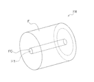
- FIG. 2 is a schematic view showing an example of a film roll FR used in the bag making and packaging machine 100.
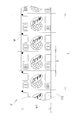
- FIG. 3 is a schematic diagram showing an example of the front side surface FS of the film F.
- the bag making and packaging machine 100 is an apparatus for forming a film F fed from a film roll FR, sealing it at a predetermined position, filling a product, sealing it again, making a bag, and then discharging it as a packaging article WP. It is.
- the film roll FR used in the bag making and packaging machine 100 is configured by winding a long film F around a cylindrical core material FC.
- the film roll FR includes a type in which the film F is fixed to the core FC with an adhesive or the like (fixed type) and a type in which the film F is not fixed (non-fixed type).
- starting end of the film roll FR refers to one end on the outer side (conveying direction side) of the film F wound around the core material FC. Further, “the end of the film roll FR” refers to one end of the film F wound around the core material FC (on the side in contact with the core material FC).
- the film F has a certain width W ⁇ b> 1 extending in the longitudinal direction L and extending in the lateral direction perpendicular to the longitudinal direction L.
- a pattern character, figure, or color
- marks M are printed on the film F at intervals of a dimension D in the vertical direction L.
- symbols such as letters and marks are not printed and are plain.
- Film F is, for example, a film in which the front side can be seen through from the back side in a normal state (translucent), or a film on which letters or figures printed on the front side can be seen from the back side by being irradiated with strong light. (For example, aluminum vapor deposition film etc.) etc. are included.
- the film F has a back side BS facing the outer side (mainly upward) of the bag making and packaging machine 100, and the front side FS is inner side (mainly downward) of the bag making and packaging machine 100. ), And is conveyed downstream.
- the film F is processed into a bag shape in the process of being conveyed in the bag making and packaging machine 100.
- the dimension D is the distance between the upper side and the lower side of the bag or the distance between the left side and the right side of the bag.
- the bag making and packaging machine 100 mainly includes a film roll support unit 10, a transport unit 20, a printing unit 30, a bag making unit 40, a film joining work auxiliary unit 50, and a control unit 70. .
- the film roll support part 10 supports the film roll FR rotatably.
- the film roll support unit 10 is arranged in the uppermost stream in the film F conveyance path in the bag making and packaging machine 100.
- the film roll support unit 10 includes a shaft 12 and a shaft motor (not shown) that rotates the shaft 12.
- the shaft 12 is mounted with the film roll FR by inserting the center hole H1 (that is, the core material FC) of the film roll FR.
- the shaft 12 is connected to the output shaft of the shaft motor and rotates in conjunction with the drive of the shaft motor.
- the operation (number of rotations) of the shaft motor is controlled by the control unit 70.
- the transport unit 20 transports the film F fed from the film roll FR to the downstream side (including the bag making unit 40) of the transport path.
- the conveyance unit 20 includes a plurality of rollers 21, a pull-down belt 22, a discharge conveyor 23, and the like, and each unit conveys the film F by performing a predetermined operation.
- the plurality of rollers 21 are mainly disposed between the film roll support unit 10 and the bag making unit 40.
- the pull-down belt 22 is disposed between the plurality of rollers 21 and the discharge conveyor 23.
- the discharge conveyor 23 is disposed on the most downstream side of the transport path. The operation of each unit in the transport unit 20 is controlled by the control unit 70.
- the roller 21 included in the transport unit 20 includes a tension roller 25 (see a two-dot chain line in FIG. 1).
- the tension roller 25 applies a predetermined tension to the film F by moving in the vertical direction.
- the tension roller 25 moves vertically upward.
- the tension roller 25 moves vertically downward.
- the amount of vertical movement of the tension roller 25 is detected by the encoder 26, and a signal corresponding to the detection result is appropriately transmitted to the control unit 70.
- the control unit 70 calculates the tension of the film F based on the signal sent from the encoder 26.
- the printing unit 30 prints predetermined information such as the date of manufacture on a predetermined position of the film F being conveyed.
- the operation of the printing unit 30 is controlled by the control unit 70.
- the bag making unit 40 is a unit that processes the film F to make a bag.
- the bag making part 40 includes a former 41, a vertical seal part 42, a horizontal seal part 43, a cutting part 44, and the like.
- the former 41 rounds the film F that has been conveyed in a flat state, and superimposes the two vertical sides of the film F.
- the vertical seal portion 42 fixes two vertical sides of the film F overlapped by the former 41.
- the horizontal seal portion 43 is fixed at a predetermined position of the film F that has been formed into a cylindrical shape through the vertical seal portion 42 so as to intersect the fixing direction of the vertical seal portion 42 substantially perpendicularly.
- the lateral seal portion 43 fixes the opening filled with the product after the product for one bag is filled through the former 41 in the fixed film F.
- the cutting part 44 cuts the film F that has undergone the fixing process in the horizontal seal part 43 at a predetermined position. The operation of each part in the bag making unit 40 is controlled by the control unit 70.
- Articles filled and filled with products by passing through the bag making unit 40 are discharged out of the bag making and packaging machine 100 by the discharge conveyor 23 of the transport unit 20.
- the film joining work assisting unit 50 is a unit for assisting work related to replacement of the film roll FR.
- the film roll FR In the bag making and packaging machine 100, when the film roll FR reaches the end, the film roll FR is exchanged with the operation stopped.
- the film bonding work In the replacement of the film roll FR, after the new film roll FR is mounted on the film roll support portion 10, the film bonding work for bonding the end of the film roll FR before the replacement and the start end of the film roll FR after the replacement Is done.
- the film joining work auxiliary unit 50 is arranged to facilitate the film joining work.
- the film bonding work auxiliary unit 50 includes a work table 55 and a light irradiation unit 60.
- the work table 55 is a plate-like member made of metal or synthetic resin.
- the work table 55 assists the work of joining the end of the film roll FR before the exchange and the start of the exchange film roll FR when the film roll FR is exchanged.
- the work table 55 plays a role as a work table for performing the film bonding work.
- the work table 55 is located between the film roll support unit 10 and the transport unit 20.
- the light irradiating unit 60 irradiates the operator with light for confirming the design printed on the front side FS of the film F from the back side BS side. Specifically, the light irradiation unit 60 irradiates the film F positioned on the work table 55 (that is, positioned between the film roll support unit 10 and the transport unit 20) from the front side surface FS direction.
- the light irradiation unit 60 includes a plurality of light emitting units 61 (see FIG. 8) configured with LED lights and the like, and a switch unit 62 (see FIG. 9) configured with semiconductor switches, relays, and the like.
- the switch unit 62 can be switched between a conductive state and a non-conductive state by the control unit 70.
- the switch unit 62 becomes conductive, the light emitting unit 61 emits light by being supplied with a predetermined driving power from a power source unit (not shown) via the switch unit 62.
- the switch unit 62 is turned off, the drive power supplied from the power supply unit is cut off, and the light emitting unit 61 stops emitting light.
- the light emitting unit 61 is disposed at a position where the film F at the joint portion of the film F (that is, on the work table 55) can be irradiated from the front side surface FS side.
- the control unit 70 is a microcomputer including a memory such as a RAM and a ROM and a CPU.
- the control unit 70 appropriately controls the operation or state of each unit included in the bag making and packaging machine 100 in accordance with a control program stored in the memory.
- FIG. 4 is a perspective view of the bag making and packaging machine 100.
- FIG. 5 is a left side view of the bag making and packaging machine 100.
- FIG. 6 is a rear view of the bag making and packaging machine 100.
- FIG. 7 is an enlarged view around the work table 55 shown in FIG.
- FIG. 8 is an enlarged view around the work table 55 shown in FIG. 7 and 8, for convenience of explanation, the film joining work auxiliary unit 50 is represented by a solid line or a two-dot chain line, and the other parts are represented by broken lines.
- (2-1) Work table 55 The work table 55 is fixed to the main body frame 110 of the bag making and packaging machine 100.
- the work table 55 is disposed above the film roll support 10 on the back side of the bag making and packaging machine 100.
- the work table 55 has a flat portion 56 extending in the left-right direction (that is, the film width W1 direction) on the upper surface portion.
- the width W2 (see FIG. 8) of the flat portion 56 is larger than the width W1 of the film F.
- the plane part 56 faces the front side surface FS of the film F sent from the film roll FR.
- a slit 57 extending in the left-right direction (that is, the width W1 direction of the film) is formed in the flat portion 56.
- the width W3 (see FIG. 8) of the slit 57 is larger than the width W1 of the film.
- the light irradiation unit 60 is disposed in a space below the work table 55 (more specifically, the plane unit 56). Specifically, a plurality (16 in this case) of light emitting units 61 are disposed below the flat surface portion 56. More specifically, the light emitting units 61 are arranged in the left-right direction (that is, in the width W1 direction of the film) at predetermined intervals immediately below the slits 57.
- the light irradiation part 60 is accommodated compactly, without occupying a big space in the main body frame 110 of the bag making packaging machine 100. FIG. For this reason, the light irradiation part 60 can be accommodated also in the main body frame of the existing (conventional) bag making and packaging machine.
- Each light emitting part 61 is arranged so that the main irradiation direction at the time of light emission extends through the slit 57 to the outside. Thereby, when the light emitting unit 61 emits light, the irradiated light passes through the slit 57. That is, the film F existing on the slit 57 of the work table 55 can be irradiated with light passing through the slit 57. As will be described later, the light emitting unit 61 blinks when the film roll FR reaches the end.
- the switch unit 62 is switched between a conductive state and a non-conductive state by being supplied with a drive voltage from the control unit 70.
- FIG. 9 is a block diagram showing the control unit 70 and each unit electrically connected to the control unit 70.
- the control unit 70 is housed in an electrical component box (not shown) fixed to the main body frame 110 of the bag making and packaging machine 100.
- the control unit 70 is electrically connected to actuators and various sensors included in the film roll support unit 10, the conveyance unit 20, the printing unit 30, and the bag making unit 40, and transmits and receives signals to and from each unit.
- the control unit 70 is electrically connected to the switch unit 62, the physical button 120, and the encoder 26 of the light irradiation unit 60, and transmits and receives signals to and from each unit.
- the control unit 70 mainly includes a communication unit 71, a storage unit 72, a shaft drive control unit 73, a conveyance control unit 74, a print control unit 75, a bag making control unit 76, an end detection unit 77, an optical unit.
- An irradiation control unit 78 mainly includes a communication unit 71, a storage unit 72, a shaft drive control unit 73, a conveyance control unit 74, a print control unit 75, a bag making control unit 76, an end detection unit 77, an optical unit.
- An irradiation control unit 78 An irradiation control unit 78.
- the communication unit 71 is a functional unit that transmits signals to other units and receives signals from other units.
- the storage unit 72 includes a RAM, a ROM, and the like, and includes a volatile storage area and a nonvolatile storage area.
- the storage unit 72 stores a control program used in processing of each unit.
- the shaft drive control unit 73 controls the start / stop and rotation speed of the film roll support unit 10 (shaft motor) in accordance with the control program.
- the conveyance control unit 74 controls the operation of each unit (the pull-down belt 22, the discharge conveyor 23, etc.) in the conveyance unit 20 in accordance with the control program.
- the printing control unit 75 controls the operation of the printing unit 30 according to the control program.
- the bag making control unit 76 controls the operation of each part (the vertical seal part 42, the horizontal seal part 43, the cutting part 44, etc.) in the bag making part 40 in accordance with the control program.
- the end detection unit 77 determines whether or not the film roll FR attached to the film roll support unit 10 has reached the end. Specifically, the end detection unit 77 monitors the tension applied to the film F (based on the position of the tension roller 25 in the vertical direction) according to the detection value of the encoder 26, and determines the end of the film roll FR from the change in tension. Detected. For example, the end detection unit 77 determines that the film roll FR has reached the end based on a temporary increase in the tension applied to the tension roller 25.
- a film roll FR of a type (fixed type) in which the end of the film F and the core material FC are fixed is more than the film F. This includes detecting the moment when it is no longer possible to send Moreover, in the type (non-fixed type) film roll FR in which the end of the film F and the core material FC are not fixed, detection of the moment when the film F is separated from the core material FC is included.
- the light irradiation control unit 78 controls the state of the switch unit 62 of the light irradiation unit 60 according to the control program.
- the light irradiation control unit 78 supplies a drive voltage to switch the switch unit 62 to a conductive state. Thereby, driving power is supplied to the light emitting unit 61 via the switch unit 62, and the light emitting unit 61 enters a light emitting state.
- the light irradiation control unit 78 stops supplying the drive voltage to switch the switch unit 62 to the non-conductive state. As a result, the drive power supplied to the light emitting unit 61 via the switch unit 62 is cut off, and the light emitting unit 61 enters a non-light emitting state (a state where no light is emitted).
- the light irradiation control unit 78 intermittently drives the drive voltage so as to switch between the conductive state and the non-conductive state of the switch unit 62 every predetermined period. Supply. Thereby, the light emission part 61 will be in the blink state in which a light emission state and a non-light emission state switch for every predetermined period. As a result, the user can visually recognize that the film roll FR has reached the end.
- the light irradiation control unit 78 stops supplying the driving voltage that has been intermittently performed so that the light emitting unit 61 is in a non-light emitting state. To do. Thereby, the light emission part 61 will be in a non-light-emission state.
- the bag making and packaging machine 100 is excellent in workability in the joining operation of the film F mainly for the following reasons.
- the film F fed out from the film roll FR is directed to the downstream side (bag making unit 40) with the back side surface BS facing the outside (mainly upward) of the bag making and packaging machine 100. Sent. For this reason, in the joining operation of the film F, it is necessary to join the films F with the back side surface BS facing the outside of the bag making and packaging machine 100. In such a case, if any mark is not included in the back side surface BS of the film F, it may be difficult to appropriately perform the joining operation of the film F.
- the light emitting unit 61 is disposed so that the film F positioned between the film roll support unit 10 and the transport unit 20 can be irradiated from the front side surface FS direction.
- work of the film F as shown in FIG.10 and FIG.11, it is possible to join the film F, confirming the character or figure transmitted by the light irradiated from the light emission part 61. It becomes.
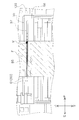
- FIG. 10 is a schematic diagram showing the state of the work table 55 and the film F (back side surface BS) positioned on the work table 55 when the light emitting unit 61 is in a non-light emitting state.
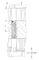
- FIG. 11 is a schematic view showing the state of the work table 55 and the film F (back side surface BS) located on the work table 55 when the light emitting unit 61 is in the light emitting state.
- the hatching part in FIG.10 and FIG.11 represents the back side surface BS (solid color) of the film F.
- FIG. 10 is a schematic diagram showing the state of the work table 55 and the film F (back side surface BS) positioned on the work table 55 when the light emitting unit 61 is in a non-light emitting state.
- FIG. 11 is a schematic view showing the state of the work table 55 and the film F (back side surface BS) located on the work table 55 when the light emitting unit 61 is in the light emitting state.
- the hatching part in FIG.10 and FIG.11
- the film F is not transmitted with light, so the design printed on the front side surface FS is from the back side BS side. I can't confirm.
- FIG. 11 shows a state in which the film M is transmitted through the light that has passed through the slit 57 and the mark M printed on the front side surface FS can be confirmed from the back side BS side.
- the film F can be joined while confirming the design such as the mark M, and the films F with the back side BS facing the outside of the bag making and packaging machine 100 are joined. In addition, it becomes easy to appropriately perform the joining operation of the film F.
- the light emission part 61 is arrange
- work of the film F at the time of film roll FR exchange it is possible to join the film F, confirming the character or figure transmitted with the light irradiated from the light emission part 61.
- FIG. As a result, even when the films F with the back surface BS facing upward are required to be joined, it is easy to perform the joining work of the films F properly. Therefore, the workability of the film F joining work is excellent.
- the light emitting unit 61 is disposed so as to irradiate the film F located immediately above the work table 55. Thereby, when the joining operation
- the light emitting unit 61 is disposed below the flat surface portion 56 of the work table 55 so as to be able to irradiate light passing through the slit 57 extending in the width direction of the film F formed on the flat surface portion 56. .
- positioning in this aspect the light emission part 61 is accommodated compactly in the main body frame 110 of the bag making packaging machine 100, without occupying a big space. That is, the light emitting unit 61 is compactly disposed in the space below the work table 55. As a result, a reduction in the compactness of the apparatus main body and a reduction in workability due to the arrangement of the light emitting unit 61 are suppressed.
- the end detection unit 77 detects that the film roll FR has reached the end, and the light-emitting unit 61 blinks or responds according to the end detection unit 77 detecting that the film roll FR has reached the end. It is configured to light up. Thereby, the user can visually recognize that the film roll FR has reached the end, and can quickly grasp the timing of the film roll FR replacement. As a result, the stop time of the bag making and packaging machine 100 can be shortened, and productivity can be improved.
- the light emission part 61 was comprised with the some LED light.
- the light emitting unit 61 is not necessarily limited to the LED light, and other light emitting units may be adopted as long as they emit light.
- a fluorescent lamp or an incandescent lamp may be employed as the light emitting unit 61.
- the slit 57 is formed in the flat portion 56 of the work table 55, and the light is emitted from the light emitting unit 61 so as to pass through the slit 57.
- the mode in which the light emitting unit 61 emits light is not necessarily limited to this.
- the flat portion 56 of the above embodiment is made of a transparent or translucent material such as synthetic resin or glass as the flat portion 56a, and the light emitting portion 61 is appropriately disposed below the flat portion 56a, and the flat portion 56a is formed. You may irradiate light so that it may permeate
- FIG. 12 is a schematic diagram showing the state of the work table 55a and the film F (back side surface BS) positioned on the work table 55a when the light emitting unit 61 is in a non-light emitting state.
- FIG. 13 is a schematic diagram showing the state of the work table 55a and the film F (back side surface BS) located on the work table 55a when the light emitting unit 61 is in the light emitting state.
- the hatching part in FIG.12 and FIG.13 represents the back side surface BS (solid color) of the film F.
- the film F is not transmitted with light, so the design printed on the front side surface FS is from the back side BS side. I can't confirm.
- FIG. 13 shows a state in which the film M is transmitted through the light passing through the flat portion 56a, and the marks M and other symbols printed on the front side surface FS can be confirmed from the back side BS side. Yes.
- the film F can be joined while confirming the design such as the mark M, and the films F with the back side BS facing the outside of the bag making and packaging machine 100 are joined. In addition, it becomes easy to appropriately perform the joining operation of the film F.
- the light emitting unit 61 is disposed in the space below the flat surface portion 56 of the work table 55.
- the light emission part 61 does not necessarily need to be arrange
- the light emitting unit 61 may be configured in a panel shape and disposed on the plane unit 56. Further, the irradiation direction may be variably arranged in the vicinity of either the left or right end portion of the plane portion 56.
- the light emission part 61 was arrange
- the light emitting unit 61 is not necessarily arranged in such a manner.
- the light emission part 61 may be arrange
- the light emitting unit 61 is configured to blink in response to the termination detecting unit 77 detecting the termination of the film roll FR.
- the light emitting unit 61 may be configured not to blink but to simply light up. That is, the light irradiation control unit 78 may be configured to supply the drive voltage continuously instead of intermittently.
- the color of light emitted from the light emitting unit 61 is not particularly limited, but may be appropriately selected according to the design of the film F and the like.
- the end detection unit 77 detects the end of the film roll FR based on a signal output from the encoder 26 (that is, the tension of the film F calculated based on the change amount of the tension roller 25). It was.
- the method by which the end detection unit 77 detects the end of the film roll FR can be changed as appropriate, and other known means may be employed.
- an encoder may be attached to the shaft 12, the other roller 21, etc., and the end detection unit 77 may be configured to detect the end of the film roll FR based on a signal sent from the encoder.
- a sensor or a camera that directly detects the end of the film roll FR may be arranged, and the end detection unit 77 may be configured to detect the end of the film roll FR based on signals sent from these devices. Good.
- the light irradiation control unit 78 switches between the conductive state and the non-conductive state of the switch unit 62, thereby switching the light emitting state and the non-light emitting state of the light emitting unit 61.
- the present invention is not limited to this, and a mechanical switch may be arranged so that the light emitting state and the non-light emitting state of the light emitting unit 61 can be switched according to switching of the switch on and off.
- control unit 70 is housed in an electrical component box (not shown) fixed to the main body frame 110 of the bag making and packaging machine 100.
- the arrangement of the control unit 70 is not necessarily limited to this, and is appropriately changed.
- part or all of the control unit 70 may be arranged in a remote place connected by a network such as a LAN or a WAN.
- the present invention can be used for a bag making and packaging machine.
Landscapes
- Engineering & Computer Science (AREA)
- Mechanical Engineering (AREA)
- Containers And Plastic Fillers For Packaging (AREA)
- Making Paper Articles (AREA)
Abstract
Description
図1は、本発明の一実施形態に係る製袋包装機100の概略構成図である。図2は、製袋包装機100において、使用されるフィルムロールFRの一例を示した模式図である。図3は、フィルムFの表側面FSの一例を示した模式図である。
図4は、製袋包装機100の斜視図である。図5は、製袋包装機100の左側面図である。図6は、製袋包装機100の背面図である。図7は、図4に示される作業テーブル55周辺の拡大図である。図8は、図6に示される作業テーブル55周辺の拡大図である。なお、図7及び図8においては、説明の便宜上、フィルム接合作業補助部50を実線又は二点鎖線で表わし、その他の部分については破線で表わしている。
作業テーブル55は、製袋包装機100の本体フレーム110に固定されている。作業テーブル55は、製袋包装機100の背面側において、フィルムロール支持部10の上方に配置されている。
光照射部60は、作業テーブル55(より詳細には、平面部56)の下方空間に配置されている。具体的には、複数(ここでは、16個)の発光部61が、平面部56の下方に配置されている。より詳細には、各発光部61は、スリット57の直下において、所定間隔おきに左右方向(すなわちフィルムの幅W1方向)に並べられている。光照射部60は、係る態様で配置されることにより、製袋包装機100の本体フレーム110内において、大きなスペースを占有することなく、コンパクトに収容されている。このため、光照射部60は、既存(従来)の製袋包装機の本体フレーム内においても収容可能である。
図9は、制御部70と、制御部70に電気的に接続される各ユニットと、を示したブロック図である。
製袋包装機100では、主として以下の理由から、フィルムFの接合作業における作業性に優れている。
(5-1)
上記実施形態では、発光部61が、フィルムロール支持部10と搬送部20との間に位置するフィルムFを、表側面FS方向から照射可能に配置されている。これにより、フィルムロールFR交換時におけるフィルムFの接合作業において、発光部61から照射される光によって透過された文字又は図形を確認しながら、フィルムFを接合することが可能となっている。その結果、裏側面BSが上を向いた状態のフィルムF同士の接合が要求される場合においても、フィルムFの接合作業を適正に行うことが容易となっている。よって、フィルムFの接合作業の作業性に優れている。
上記実施形態では、発光部61は、作業テーブル55の直上に位置するフィルムFを、照射するように配置されている。これにより、フィルムFの接合作業が行われる際、作業テーブル55上に位置するフィルムFの、文字又は図形が透過される。その結果、フィルムFの接合作業を適正に行うことがさらに容易となっている。
上記実施形態では、発光部61は、作業テーブル55の平面部56の下方において、平面部56に形成されたフィルムFの幅方向に延びるスリット57、を通過する光を照射可能に配置されている。係る態様で配置されることにより、発光部61は、製袋包装機100の本体フレーム110内において、大きなスペースを占有することなく、コンパクトに収容されている。すなわち、発光部61は、作業テーブル55の下方のスペースにコンパクトに配置されている。その結果、発光部61が配置されることによる、装置本体のコンパクト性の低下や、作業性の低下が、抑制されている。
上記実施形態では、終端検知部77はフィルムロールFRが終端に達したことを検知し、発光部61はフィルムロールFRが終端に達したことを終端検知部77が検知したことに応じて点滅又は点灯するように構成されている。これにより、ユーザが、フィルムロールFRが終端に達したことを視覚的に認知でき、フィルムロールFR交換のタイミングを迅速に把握できるようになっている。その結果、製袋包装機100の停止時間を短縮することが可能となっており、生産性を向上しうる。
上記実施形態の製袋包装機100は、以下の変形例に示すように適宜変形が可能である。なお、各変形例は、矛盾が生じない範囲で他の変形例と組み合わせて適用されてもよい。
上記実施形態では、発光部61は、複数のLEDライトで構成された。しかし、発光部61は、必ずしもLEDライトに限定されず、光を照射するものであれば他のものを採用されてもよい。例えば、発光部61として、蛍光灯や白熱電球を採用されてもよい。
上記実施形態では、作業テーブル55の平面部56にスリット57が形成され、係るスリット57を通過するように発光部61から光が照射された。しかし、発光部61が光を照射する態様については、必ずしもこれに限定されない。例えば、上記実施形態の平面部56を平面部56aとして合成樹脂やガラス等の透明や半透明の素材で構成し、係る平面部56aの下方に発光部61を適宜配置して、平面部56aを透過するように光を照射させてもよい。係る場合、スリット57については省略可能である。
上記実施形態では、発光部61は、作業テーブル55の平面部56の下方空間に配置された。しかし、発光部61は、必ずしも係る態様で配置される必要はなく、他のスペースに配置されてもよい。例えば、発光部61は、パネル状に構成されて平面部56上に配置されてもよい。また、平面部56の左右いずれかの端部付近において照射方向を可変に配置されてもよい。
上記実施形態では、発光部61は、作業テーブル55(平面部56)上に位置するフィルムFを、表側面FS側から照射可能に配置されていた。しかし、発光部61は、必ずしも係る態様で配置される必要はない。例えば、発光部61は、フィルムロール支持部10と作業テーブル55の間に位置するフィルムFを、表側面FS側から照射可能な態様で配置されてもよい。
上記実施形態では、発光部61は、終端検知部77がフィルムロールFRの終端を検知したことに応じて、点滅するように構成されていた。しかし、係る場合において、発光部61が、点滅するのではなく、単に点灯するように構成されてもよい。すなわち、光照射制御部78が、間欠的にではなく、連続的に、駆動電圧の供給を行うように構成してもよい。
上記実施形態では、発光部61が発する光の色については、特に限定されていなかったが、フィルムFの図柄等に応じて適宜、選択されればよい。
上記実施形態では、終端検知部77は、フィルムロールFRの終端を、エンコーダ26から出力される信号(すなわち、テンションローラ25の変化量に基づいて算出されるフィルムFの張力)に基づいて検知していた。しかし、終端検知部77がフィルムロールFRの終端を検知する方法については適宜変更が可能であり、他の公知の手段が採用されてもよい。例えば、シャフト12や他のローラ21等にエンコーダを取り付け、終端検知部77が、当該エンコーダから送られる信号に基づいてフィルムロールFRの終端を検知するように構成してもよい。また、フィルムロールFRの終端を直接的に検出するセンサやカメラを配置し、終端検知部77がこれらの機器から送られる信号に基づいて、フィルムロールFRの終端を検知するように構成してもよい。
上記実施形態では、光照射制御部78がスイッチ部62の導通状態と非導通状態とを切り換えることで、発光部61の発光状態と非発光状態とが切り換えられていた。しかし、これに限定されず、機械的なスイッチを配置し、当該スイッチのオンとオフの切り換えに応じて、発光部61の発光状態と非発光状態とが切り換えられるように構成されてもよい。
上記実施形態では、制御部70は、製袋包装機100の本体フレーム110に固定された電装品ボックス(図示省略)内に収容されていた。しかし、制御部70の配置態様については必ずしもこれに限定されず、適宜変更である。例えば、制御部70の一部又は全部は、LANやWAN等のネットワークで接続された遠隔地に配置されてもよい。
12 :シャフト
20 :搬送部
21 :ローラ
22 :プルダウンベルト
23 :排出コンベア
25 :テンションローラ
26 :エンコーダ
30 :印字部
40 :製袋部
41 :フォーマ
42 :縦シール部
43 :横シール部
44 :切断部
50 :フィルム接合作業補助部
55、55a:作業テーブル
56、56a: 平面部
57 :スリット
60 :光照射部
61 :発光部
62 :スイッチ部
70 :制御部
71 :通信部
72 :記憶部
73 :シャフト駆動制御部
74 :搬送制御部
75 :印刷制御部
76 :製袋制御部
77 :終端検知部
78 :光照射制御部
100 :製袋包装機
110 :本体フレーム
120 :物理ボタン
BS :裏側面
F :フィルム
FR :フィルムロール
FS :表側面
M :マーク
Claims (4)
- 表側面に文字又は図形が印刷されたフィルムを用いる製袋包装機であって、
前記フィルムがロール状に巻かれたフィルムロールを支持するフィルムロール支持部と、
前記フィルムを加工して袋を作る製袋部と、
前記フィルムロール支持部と前記製袋部との間に位置し、前記フィルムを前記製袋部へ送る搬送部と、
前記フィルムロール支持部と前記搬送部との間に位置する前記フィルムを、前記表側面方向から照射する発光部と、
を備える、
製袋包装機。 - 前記フィルムロール支持部と前記搬送部との間に位置し、前記フィルムロールの交換時に交換前の前記フィルムロールの終端と交換用の前記フィルムロールの始端とを接合する作業を補助する、作業テーブルをさらに備え、
前記発光部は、前記作業テーブル上に位置する前記フィルムを照射する、
請求項1に記載の製袋包装機。 - 前記作業テーブルは、前記フィルムロールから送られる前記フィルムの前記表側面に面する平面部を含み、
前記平面部には、前記フィルムの幅方向に延びるスリットが形成され、
前記発光部は、前記平面部の下方に配置され、前記スリットを通過するように光を照射する、
請求項2に記載の製袋包装機。 - 前記フィルムロール支持部に支持される前記フィルムロールが終端に達したことを検知する終端検知部をさらに備え、
前記発光部は、前記フィルムロールが終端に達したことを前記終端検知部が検知したことに応じて、点滅又は点灯する、
請求項1から3のいずれか1項に記載の製袋包装機。
Priority Applications (5)
| Application Number | Priority Date | Filing Date | Title |
|---|---|---|---|
| US15/555,977 US10875734B2 (en) | 2015-03-19 | 2016-01-26 | Bag making and packaging machine |
| EP16764531.6A EP3272662B1 (en) | 2015-03-19 | 2016-01-26 | Bag manufacturing and packing machine |
| MX2017011663A MX390574B (es) | 2015-03-19 | 2016-01-26 | Máquina de manufactura y empaque de bolsas. |
| CN201680014849.1A CN107406159B (zh) | 2015-03-19 | 2016-01-26 | 制袋包装机 |
| AU2016234766A AU2016234766B2 (en) | 2015-03-19 | 2016-01-26 | Bag making and packaging machine |
Applications Claiming Priority (2)
| Application Number | Priority Date | Filing Date | Title |
|---|---|---|---|
| JP2015056139A JP6534838B2 (ja) | 2015-03-19 | 2015-03-19 | 製袋包装機 |
| JP2015-056139 | 2015-03-19 |
Publications (1)
| Publication Number | Publication Date |
|---|---|
| WO2016147700A1 true WO2016147700A1 (ja) | 2016-09-22 |
Family
ID=56919844
Family Applications (1)
| Application Number | Title | Priority Date | Filing Date |
|---|---|---|---|
| PCT/JP2016/052193 Ceased WO2016147700A1 (ja) | 2015-03-19 | 2016-01-26 | 製袋包装機 |
Country Status (7)
| Country | Link |
|---|---|
| US (1) | US10875734B2 (ja) |
| EP (1) | EP3272662B1 (ja) |
| JP (1) | JP6534838B2 (ja) |
| CN (1) | CN107406159B (ja) |
| AU (1) | AU2016234766B2 (ja) |
| MX (1) | MX390574B (ja) |
| WO (1) | WO2016147700A1 (ja) |
Families Citing this family (6)
| Publication number | Priority date | Publication date | Assignee | Title |
|---|---|---|---|---|
| CN108715087B (zh) * | 2018-06-27 | 2024-09-24 | 广东莱尔新材料科技股份有限公司 | 一种薄膜复合机 |
| CN109159978A (zh) * | 2018-06-29 | 2019-01-08 | 铜陵市明科包装技术有限公司 | 一种保证包装质量的包装机 |
| JP7359406B2 (ja) * | 2018-11-02 | 2023-10-11 | 株式会社川島製作所 | 紙継ぎ構造を備えた製袋充填包装機 |
| JP7401982B2 (ja) * | 2019-05-27 | 2023-12-20 | 株式会社東京自働機械製作所 | フィルム供給装置 |
| NL2031811B1 (en) * | 2022-05-10 | 2023-11-17 | Vmi Holland Bv | Assembly and method for handling a string of consecutive medicament pouches |
| EP4438535A1 (en) * | 2023-03-20 | 2024-10-02 | Ishida Co., Ltd. | Bag-making and packaging machine |
Citations (2)
| Publication number | Priority date | Publication date | Assignee | Title |
|---|---|---|---|---|
| JPH04191237A (ja) * | 1990-11-27 | 1992-07-09 | Tokihisa Masuda | 包装フイルムシートの連続接続方法及び装置 |
| JP2011195152A (ja) * | 2010-03-17 | 2011-10-06 | Omori Mach Co Ltd | 逆ピロー包装機および包装方法 |
Family Cites Families (23)
| Publication number | Priority date | Publication date | Assignee | Title |
|---|---|---|---|---|
| US2899143A (en) * | 1959-08-11 | crosfield etal | ||
| DE2439318A1 (de) * | 1974-08-16 | 1976-02-26 | Phoenix Gummiwerke Ag | Vorrichtung zum staendigen ueberwachen von laufenden gewebebahnen |
| US4137528A (en) * | 1977-08-25 | 1979-01-30 | Moore Business Forms, Inc. | Faulty window construction detecting apparatus |
| US4494948A (en) * | 1982-07-06 | 1985-01-22 | Sperry Corporation | Air controlled paper stacker |
| JPS6061234U (ja) * | 1983-09-29 | 1985-04-27 | 沖電気工業株式会社 | 用紙排出部の位置検出装置 |
| JPH0279359U (ja) * | 1988-12-05 | 1990-06-19 | ||
| US5766389A (en) * | 1995-12-29 | 1998-06-16 | Kimberly-Clark Worldwide, Inc. | Disposable absorbent article having a registered graphic and process for making |
| DE29611789U1 (de) * | 1996-07-06 | 1996-09-12 | KRAMPS Druckereibetriebe GmbH & Co. KG i.K, 44867 Bochum | Vorrichtung zum Begutachten von Papier einer Papierrolle |
| US6354984B1 (en) * | 1999-04-02 | 2002-03-12 | Kimberly-Clark Worldwide, Inc. | Indirect registration of elements of web-derived product |
| EP1106337A3 (en) * | 1999-12-02 | 2002-06-12 | Reynolds Consumer Products, Inc. | Methods of manufacturing reclosable packages having a slider device |
| US6893528B2 (en) * | 2000-11-01 | 2005-05-17 | Adalis Corporation | Web material advance system for web material applicator |
| EP1339609B1 (de) * | 2000-11-24 | 2005-05-25 | CFS Germany GmbH | Verfahren und vorrichtung zum positionieren von folienbahnen einer verpackungsvorrichtung |
| WO2002098737A1 (fr) | 2001-06-05 | 2002-12-12 | Ishida Co., Ltd. | Machine de fabrication de sacs et d'emballage |
| US20070179036A1 (en) * | 2006-02-02 | 2007-08-02 | Cmd Corporation | Method And Apparatus For A Bag Machine |
| JP2009535280A (ja) * | 2006-04-27 | 2009-10-01 | エスセーアー・ハイジーン・プロダクツ・アーベー | 少なくとも1つの原則的に連続した材料ウェブの配置の同期に使用される同期マークを検出するための方法および設備 |
| EP2379329B1 (en) * | 2008-12-18 | 2016-02-17 | Tetra Laval Holdings & Finance S.A. | Method of controlling the relative position between printed patterns and non-printed patterns on a web-shaped material and a system used in the method |
| CN101654198B (zh) * | 2009-09-08 | 2012-03-28 | 安庆市恒昌机械制造有限责任公司 | 卫生用品生产线上的连续基材图案的定位复合及拼接装置 |
| JP2011230782A (ja) * | 2010-04-26 | 2011-11-17 | Ishida Co Ltd | 製袋包装機 |
| JP5830233B2 (ja) * | 2010-09-17 | 2015-12-09 | 日東電工株式会社 | シート接合体の製造方法及びシート接合体の製造装置 |
| US9169099B2 (en) * | 2011-03-25 | 2015-10-27 | Max Co., Ltd | Long medium |
| ITTO20120683A1 (it) * | 2012-07-31 | 2014-02-01 | Sidel Spa Con Socio Unico | Dispositivo e metodo per la giunzione di nastri provvisti di decori ripetuti |
| JP6389874B2 (ja) * | 2013-05-16 | 2018-09-12 | ランパク コーポレーション | ダンネージ変換機のジャム検出システム及び方法 |
| JP6431931B2 (ja) * | 2015-01-09 | 2018-11-28 | 富士通フロンテック株式会社 | 紙葉類収容装置及び紙葉類収容方法 |
-
2015
- 2015-03-19 JP JP2015056139A patent/JP6534838B2/ja active Active
-
2016
- 2016-01-26 EP EP16764531.6A patent/EP3272662B1/en active Active
- 2016-01-26 US US15/555,977 patent/US10875734B2/en active Active
- 2016-01-26 AU AU2016234766A patent/AU2016234766B2/en active Active
- 2016-01-26 MX MX2017011663A patent/MX390574B/es unknown
- 2016-01-26 WO PCT/JP2016/052193 patent/WO2016147700A1/ja not_active Ceased
- 2016-01-26 CN CN201680014849.1A patent/CN107406159B/zh active Active
Patent Citations (2)
| Publication number | Priority date | Publication date | Assignee | Title |
|---|---|---|---|---|
| JPH04191237A (ja) * | 1990-11-27 | 1992-07-09 | Tokihisa Masuda | 包装フイルムシートの連続接続方法及び装置 |
| JP2011195152A (ja) * | 2010-03-17 | 2011-10-06 | Omori Mach Co Ltd | 逆ピロー包装機および包装方法 |
Non-Patent Citations (1)
| Title |
|---|
| See also references of EP3272662A4 * |
Also Published As
| Publication number | Publication date |
|---|---|
| US10875734B2 (en) | 2020-12-29 |
| MX390574B (es) | 2025-03-11 |
| AU2016234766B2 (en) | 2018-06-28 |
| AU2016234766A1 (en) | 2017-10-12 |
| MX2017011663A (es) | 2017-11-06 |
| JP6534838B2 (ja) | 2019-06-26 |
| EP3272662A1 (en) | 2018-01-24 |
| CN107406159B (zh) | 2020-03-03 |
| JP2016175661A (ja) | 2016-10-06 |
| EP3272662A4 (en) | 2018-04-11 |
| US20180057294A1 (en) | 2018-03-01 |
| EP3272662B1 (en) | 2022-04-13 |
| CN107406159A (zh) | 2017-11-28 |
Similar Documents
| Publication | Publication Date | Title |
|---|---|---|
| WO2016147700A1 (ja) | 製袋包装機 | |
| CN111003275B (zh) | 制袋包装机 | |
| CN111003277B (zh) | 制袋包装机 | |
| CN111003276B (zh) | 制袋包装机 | |
| KR101389718B1 (ko) | 포장필름의 연속 공급장치 | |
| JP2010089161A (ja) | レーザーパケットマーキングユニット | |
| WO2015178480A1 (ja) | 搬送装置 | |
| JP5498770B2 (ja) | 紙継装置 | |
| JP5878227B1 (ja) | 三次元物体の造形に用いるフィード機構 | |
| JP4982313B2 (ja) | 転写用フィルムの巻取り方法及び印刷用紙への転写装置 | |
| CN1939710A (zh) | 用于制造香烟盒的方法及装置 | |
| JP6251819B2 (ja) | デジタル印刷機 | |
| JP2004025871A (ja) | 枚葉紙を処理する打ち抜き・型押し機のくわえづめキャリッジ用の位置決め装置 | |
| KR101903731B1 (ko) | 롤원단 가공 시스템 | |
| RU2272759C2 (ru) | Упаковочная машина для упаковывания жидких пищевых продуктов, способ контроля положения вспомогательных средств на полотне материала в ней и устройство контроля положения вспомогательных средств на полотне упаковочного материала для такой машины | |
| WO2016059995A1 (ja) | デジタル印刷機 | |
| JP2019119508A (ja) | 包装機における縦継ぎ方法及び装置 | |
| JP6030036B2 (ja) | 横形製袋充填機 | |
| CN203439307U (zh) | 包装机 | |
| JP5465561B2 (ja) | 逆ピロー包装機および包装方法 | |
| JP2006001628A (ja) | 新聞を包装するための方法、およびこの方法を実施するための装置 | |
| JP2009007047A (ja) | 包装フィルム切断装置 | |
| KR101697619B1 (ko) | 디지털 프린팅 머신용 인쇄지의 이송장치 | |
| JPH107102A (ja) | 製袋包装機 | |
| JP6401332B2 (ja) | 抜き加工装置 |
Legal Events
| Date | Code | Title | Description |
|---|---|---|---|
| 121 | Ep: the epo has been informed by wipo that ep was designated in this application |
Ref document number: 16764531 Country of ref document: EP Kind code of ref document: A1 |
|
| WWE | Wipo information: entry into national phase |
Ref document number: 15555977 Country of ref document: US |
|
| WWE | Wipo information: entry into national phase |
Ref document number: MX/A/2017/011663 Country of ref document: MX |
|
| NENP | Non-entry into the national phase |
Ref country code: DE |
|
| ENP | Entry into the national phase |
Ref document number: 2016234766 Country of ref document: AU Date of ref document: 20160126 Kind code of ref document: A |