WO2016148010A1 - 無方向性電磁鋼板およびその製造方法 - Google Patents
無方向性電磁鋼板およびその製造方法 Download PDFInfo
- Publication number
- WO2016148010A1 WO2016148010A1 PCT/JP2016/057572 JP2016057572W WO2016148010A1 WO 2016148010 A1 WO2016148010 A1 WO 2016148010A1 JP 2016057572 W JP2016057572 W JP 2016057572W WO 2016148010 A1 WO2016148010 A1 WO 2016148010A1
- Authority
- WO
- WIPO (PCT)
- Prior art keywords
- hot
- cold
- rolled
- content
- rolled sheet
- Prior art date
- Legal status (The legal status is an assumption and is not a legal conclusion. Google has not performed a legal analysis and makes no representation as to the accuracy of the status listed.)
- Ceased
Links
Images


Classifications
-
- C—CHEMISTRY; METALLURGY
- C21—METALLURGY OF IRON
- C21D—MODIFYING THE PHYSICAL STRUCTURE OF FERROUS METALS; GENERAL DEVICES FOR HEAT TREATMENT OF FERROUS OR NON-FERROUS METALS OR ALLOYS; MAKING METAL MALLEABLE, e.g. BY DECARBURISATION OR TEMPERING
- C21D9/00—Heat treatment, e.g. annealing, hardening, quenching or tempering, adapted for particular articles; Furnaces therefor
- C21D9/46—Heat treatment, e.g. annealing, hardening, quenching or tempering, adapted for particular articles; Furnaces therefor for sheet metals
-
- C—CHEMISTRY; METALLURGY
- C22—METALLURGY; FERROUS OR NON-FERROUS ALLOYS; TREATMENT OF ALLOYS OR NON-FERROUS METALS
- C22C—ALLOYS
- C22C38/00—Ferrous alloys, e.g. steel alloys
- C22C38/02—Ferrous alloys, e.g. steel alloys containing silicon
-
- C—CHEMISTRY; METALLURGY
- C21—METALLURGY OF IRON
- C21D—MODIFYING THE PHYSICAL STRUCTURE OF FERROUS METALS; GENERAL DEVICES FOR HEAT TREATMENT OF FERROUS OR NON-FERROUS METALS OR ALLOYS; MAKING METAL MALLEABLE, e.g. BY DECARBURISATION OR TEMPERING
- C21D6/00—Heat treatment of ferrous alloys
- C21D6/008—Heat treatment of ferrous alloys containing Si
-
- C—CHEMISTRY; METALLURGY
- C21—METALLURGY OF IRON
- C21D—MODIFYING THE PHYSICAL STRUCTURE OF FERROUS METALS; GENERAL DEVICES FOR HEAT TREATMENT OF FERROUS OR NON-FERROUS METALS OR ALLOYS; MAKING METAL MALLEABLE, e.g. BY DECARBURISATION OR TEMPERING
- C21D8/00—Modifying the physical properties of ferrous metals or ferrous alloys by deformation combined with, or followed by, heat treatment
- C21D8/12—Modifying the physical properties of ferrous metals or ferrous alloys by deformation combined with, or followed by, heat treatment during manufacturing of articles with special electromagnetic properties
- C21D8/1216—Modifying the physical properties of ferrous metals or ferrous alloys by deformation combined with, or followed by, heat treatment during manufacturing of articles with special electromagnetic properties characterised by the working steps
- C21D8/1222—Hot rolling
-
- C—CHEMISTRY; METALLURGY
- C21—METALLURGY OF IRON
- C21D—MODIFYING THE PHYSICAL STRUCTURE OF FERROUS METALS; GENERAL DEVICES FOR HEAT TREATMENT OF FERROUS OR NON-FERROUS METALS OR ALLOYS; MAKING METAL MALLEABLE, e.g. BY DECARBURISATION OR TEMPERING
- C21D8/00—Modifying the physical properties of ferrous metals or ferrous alloys by deformation combined with, or followed by, heat treatment
- C21D8/12—Modifying the physical properties of ferrous metals or ferrous alloys by deformation combined with, or followed by, heat treatment during manufacturing of articles with special electromagnetic properties
- C21D8/1216—Modifying the physical properties of ferrous metals or ferrous alloys by deformation combined with, or followed by, heat treatment during manufacturing of articles with special electromagnetic properties characterised by the working steps
- C21D8/1233—Cold rolling
-
- C—CHEMISTRY; METALLURGY
- C21—METALLURGY OF IRON
- C21D—MODIFYING THE PHYSICAL STRUCTURE OF FERROUS METALS; GENERAL DEVICES FOR HEAT TREATMENT OF FERROUS OR NON-FERROUS METALS OR ALLOYS; MAKING METAL MALLEABLE, e.g. BY DECARBURISATION OR TEMPERING
- C21D8/00—Modifying the physical properties of ferrous metals or ferrous alloys by deformation combined with, or followed by, heat treatment
- C21D8/12—Modifying the physical properties of ferrous metals or ferrous alloys by deformation combined with, or followed by, heat treatment during manufacturing of articles with special electromagnetic properties
- C21D8/1244—Modifying the physical properties of ferrous metals or ferrous alloys by deformation combined with, or followed by, heat treatment during manufacturing of articles with special electromagnetic properties characterised by the heat treatment
- C21D8/1261—Modifying the physical properties of ferrous metals or ferrous alloys by deformation combined with, or followed by, heat treatment during manufacturing of articles with special electromagnetic properties characterised by the heat treatment following hot rolling
-
- C—CHEMISTRY; METALLURGY
- C21—METALLURGY OF IRON
- C21D—MODIFYING THE PHYSICAL STRUCTURE OF FERROUS METALS; GENERAL DEVICES FOR HEAT TREATMENT OF FERROUS OR NON-FERROUS METALS OR ALLOYS; MAKING METAL MALLEABLE, e.g. BY DECARBURISATION OR TEMPERING
- C21D8/00—Modifying the physical properties of ferrous metals or ferrous alloys by deformation combined with, or followed by, heat treatment
- C21D8/12—Modifying the physical properties of ferrous metals or ferrous alloys by deformation combined with, or followed by, heat treatment during manufacturing of articles with special electromagnetic properties
- C21D8/1244—Modifying the physical properties of ferrous metals or ferrous alloys by deformation combined with, or followed by, heat treatment during manufacturing of articles with special electromagnetic properties characterised by the heat treatment
- C21D8/1272—Final recrystallisation annealing
-
- C—CHEMISTRY; METALLURGY
- C22—METALLURGY; FERROUS OR NON-FERROUS ALLOYS; TREATMENT OF ALLOYS OR NON-FERROUS METALS
- C22C—ALLOYS
- C22C38/00—Ferrous alloys, e.g. steel alloys
- C22C38/001—Ferrous alloys, e.g. steel alloys containing N
-
- C—CHEMISTRY; METALLURGY
- C22—METALLURGY; FERROUS OR NON-FERROUS ALLOYS; TREATMENT OF ALLOYS OR NON-FERROUS METALS
- C22C—ALLOYS
- C22C38/00—Ferrous alloys, e.g. steel alloys
- C22C38/002—Ferrous alloys, e.g. steel alloys containing In, Mg, or other elements not provided for in one single group C22C38/001 - C22C38/60
-
- C—CHEMISTRY; METALLURGY
- C22—METALLURGY; FERROUS OR NON-FERROUS ALLOYS; TREATMENT OF ALLOYS OR NON-FERROUS METALS
- C22C—ALLOYS
- C22C38/00—Ferrous alloys, e.g. steel alloys
- C22C38/004—Very low carbon steels, i.e. having a carbon content of less than 0,01%
-
- C—CHEMISTRY; METALLURGY
- C22—METALLURGY; FERROUS OR NON-FERROUS ALLOYS; TREATMENT OF ALLOYS OR NON-FERROUS METALS
- C22C—ALLOYS
- C22C38/00—Ferrous alloys, e.g. steel alloys
- C22C38/04—Ferrous alloys, e.g. steel alloys containing manganese
-
- C—CHEMISTRY; METALLURGY
- C22—METALLURGY; FERROUS OR NON-FERROUS ALLOYS; TREATMENT OF ALLOYS OR NON-FERROUS METALS
- C22C—ALLOYS
- C22C38/00—Ferrous alloys, e.g. steel alloys
- C22C38/06—Ferrous alloys, e.g. steel alloys containing aluminium
-
- C—CHEMISTRY; METALLURGY
- C22—METALLURGY; FERROUS OR NON-FERROUS ALLOYS; TREATMENT OF ALLOYS OR NON-FERROUS METALS
- C22C—ALLOYS
- C22C38/00—Ferrous alloys, e.g. steel alloys
- C22C38/12—Ferrous alloys, e.g. steel alloys containing tungsten, tantalum, molybdenum, vanadium, or niobium
-
- C—CHEMISTRY; METALLURGY
- C22—METALLURGY; FERROUS OR NON-FERROUS ALLOYS; TREATMENT OF ALLOYS OR NON-FERROUS METALS
- C22C—ALLOYS
- C22C38/00—Ferrous alloys, e.g. steel alloys
- C22C38/14—Ferrous alloys, e.g. steel alloys containing titanium or zirconium
-
- H—ELECTRICITY
- H01—ELECTRIC ELEMENTS
- H01F—MAGNETS; INDUCTANCES; TRANSFORMERS; SELECTION OF MATERIALS FOR THEIR MAGNETIC PROPERTIES
- H01F1/00—Magnets or magnetic bodies characterised by the magnetic materials therefor; Selection of materials for their magnetic properties
- H01F1/01—Magnets or magnetic bodies characterised by the magnetic materials therefor; Selection of materials for their magnetic properties of inorganic materials
- H01F1/03—Magnets or magnetic bodies characterised by the magnetic materials therefor; Selection of materials for their magnetic properties of inorganic materials characterised by their coercivity
- H01F1/12—Magnets or magnetic bodies characterised by the magnetic materials therefor; Selection of materials for their magnetic properties of inorganic materials characterised by their coercivity of soft-magnetic materials
- H01F1/14—Magnets or magnetic bodies characterised by the magnetic materials therefor; Selection of materials for their magnetic properties of inorganic materials characterised by their coercivity of soft-magnetic materials metals or alloys
- H01F1/16—Magnets or magnetic bodies characterised by the magnetic materials therefor; Selection of materials for their magnetic properties of inorganic materials characterised by their coercivity of soft-magnetic materials metals or alloys in the form of sheets
-
- C—CHEMISTRY; METALLURGY
- C21—METALLURGY OF IRON
- C21D—MODIFYING THE PHYSICAL STRUCTURE OF FERROUS METALS; GENERAL DEVICES FOR HEAT TREATMENT OF FERROUS OR NON-FERROUS METALS OR ALLOYS; MAKING METAL MALLEABLE, e.g. BY DECARBURISATION OR TEMPERING
- C21D2201/00—Treatment for obtaining particular effects
- C21D2201/05—Grain orientation
-
- Y—GENERAL TAGGING OF NEW TECHNOLOGICAL DEVELOPMENTS; GENERAL TAGGING OF CROSS-SECTIONAL TECHNOLOGIES SPANNING OVER SEVERAL SECTIONS OF THE IPC; TECHNICAL SUBJECTS COVERED BY FORMER USPC CROSS-REFERENCE ART COLLECTIONS [XRACs] AND DIGESTS
- Y02—TECHNOLOGIES OR APPLICATIONS FOR MITIGATION OR ADAPTATION AGAINST CLIMATE CHANGE
- Y02P—CLIMATE CHANGE MITIGATION TECHNOLOGIES IN THE PRODUCTION OR PROCESSING OF GOODS
- Y02P10/00—Technologies related to metal processing
- Y02P10/20—Recycling
Definitions
- the present invention relates to a non-oriented electrical steel sheet with low high-frequency iron loss and a manufacturing method for producing this non-oriented electrical steel sheet with high productivity. More specifically, the present invention relates to a non-oriented electrical steel sheet suitable for a material for an iron core of electrical equipment that requires high energy efficiency, small dimensions, and high output, and a method for manufacturing the same. Examples of such electric equipment include a drive motor mounted on a compressor motor of an air conditioner, a hybrid vehicle, an electric vehicle, and a fuel cell vehicle, and a small generator mounted on a two-wheeled vehicle and a home cogeneration system.
- This application claims priority based on Japanese Patent Application No. 2015-053095 filed in Japan on March 17, 2015, the contents of which are incorporated herein by reference.
- the rotational speed of the drive motor is increased in order to compensate for the torque reduction accompanying downsizing.
- the rotational speed is increased, the frequency of the magnetic field applied to the steel sheet increases and the iron loss increases. Therefore, the steel sheet is required to reduce iron loss (high frequency iron loss) at a high frequency.
- iron loss high frequency iron loss
- reduction of plate thickness, increase of specific resistance, and reduction of impurity elements have been adopted.
- the specific resistance of a steel sheet is increased by increasing the content of alloy elements such as Si and Al in the steel sheet.
- Patent Document 1 contains Si: 1.5% to 3.5%, Al: 0.6% to 3.0%, and (Al / (Si + Al)) of 0.3% by mass.
- a method for controlling the average crystal grain size and Vickers hardness of a hot-rolled annealed plate manufactured from steel satisfying .about.0.5 is disclosed. Further, Patent Document 1 discloses that this method can provide a non-oriented electrical steel sheet with high rupture resistance of a hot-rolled annealed sheet and low high-frequency iron loss without impairing productivity. . That is, unlike the methods disclosed in Patent Documents 2 to 5, the method disclosed in Patent Document 1 adjusts the ratio of the Al content to the total of the Si content and the Al content.
- the present invention has been made in view of the above problems, and further increases the ratio of the Al content to the range where the high-frequency iron loss has increased due to the increase in hysteresis loss (a range exceeding a certain upper limit).
- Another object of the present invention is to provide a non-oriented electrical steel sheet with high productivity and low high-frequency iron loss.
- the present inventors have conducted intensive research on changes in iron loss, particularly hysteresis loss, when various chemical elements are added to steel containing a predetermined amount of Al.
- the ratio of the Al content in the steel is increased to the extent that the high-frequency iron loss has been increased due to the increase in hysteresis loss so far, if the steel contains only a predetermined amount of P, P is a steel plate. It has been found that the high-frequency iron loss does not deteriorate (does not increase) due to the effect on the texture.
- the steel sheet has a texture in which the ratio I ⁇ 100 ⁇ / I ⁇ 111 ⁇ of the intensity I ⁇ 100 ⁇ of the ⁇ 100 ⁇ plane to the intensity I ⁇ 111 ⁇ of the ⁇ 111 ⁇ plane is within a predetermined range.
- This texture can suppress the generation of deformation twins when punched and can further reduce high-frequency iron loss.
- the present invention has been made based on these findings, and the gist thereof is as follows.
- the non-oriented electrical steel sheet according to one aspect of the present invention is, in mass%, C: 0% to 0.0050%, Si: 0.50% to 2.70%, Mn: 0.10% to 3.00%, Al: 1.00% to 2.70%, P: 0.050% to 0.100%, S: 0% to 0.0060%, N: 0% to 0.0050%, Ti : 0% to 0.008%, V: 0% to 0.008%, Nb: 0% to 0.008%, Zr: 0% to 0.008%, the balance being Fe and impurities
- the chemical composition satisfies the following formula (1), the following formula (2) and the following formula (3), and the crystal orientation distribution function and the plate thickness in the vicinity of the surface from the positive dot diagram measured by the X-ray diffraction method.
- the intensity I ⁇ 100 ⁇ of the ⁇ 100 ⁇ plane and the intensity I ⁇ 111 ⁇ of the ⁇ 111 ⁇ plane, which are determined by obtaining an average with the center crystal orientation distribution function, are Satisfies serial formula (4), and a resistivity at room temperature of 60.0 ⁇ 10 -8 ⁇ ⁇ m or more, the thickness is 0.05 mm ⁇ 0.40 mm.
- 0.50 ⁇ Al / (Si + Al + 0.5 ⁇ Mn) ⁇ 0.83 (1) 1.28 ⁇ Si + Al / 2 + Mn / 4 + 5 ⁇ P ⁇ 3.90 (2) 4.0 ⁇ Si + Al + 0.5 ⁇ Mn ⁇ 7.0 (3) 0.50 ⁇ I ⁇ 100 ⁇ / I ⁇ 111 ⁇ ⁇ 1.40 (4)
- a method for producing a non-oriented electrical steel sheet according to an embodiment of the present invention is, in mass%, C: 0% to 0.0050%, Si: 0.50% to 2.70%, Mn: 0.00. 10% to 3.00%, Al: 1.00% to 2.70%, P: 0.050% to 0.100%, S: 0% to 0.0060%, N: 0% to 0.0050 %, Ti: 0% to 0.008%, V: 0% to 0.008%, Nb: 0% to 0.008%, Zr: 0% to 0.008%, the balance being Fe and impurities Hot-rolling which manufactures a hot-rolled sheet by hot-rolling to the slab which has the chemical composition which consists of these, and the said chemical composition satisfies following formula (5), following formula (6), and following formula (7)
- the method for producing a non-oriented electrical steel sheet according to (2) is a hot-rolled sheet in which hot-rolled sheet annealing is performed on the hot-rolled sheet between the hot-rolling step and the cold-rolling step. You may further have an annealing process.
- the electrical equipment can be made smaller, and the output and energy efficiency of the electrical equipment can be further increased.
- the non-oriented electrical steel sheet can be punched more easily, heating can be omitted when the non-oriented electrical steel sheet is punched, and the frequency of mold replacement accompanying wear can be reduced. Therefore, the manufacturing cost of the electric device can be reduced.
- the non-directional electromagnetic wave even if cold rolling becomes difficult by increasing the specific resistance of the non-oriented electrical steel sheet, the non-directional electromagnetic wave further improving the high-frequency iron loss without reducing productivity and yield.
- a steel plate can be manufactured stably at low cost. Therefore, the industrial value of the non-oriented electrical steel sheet according to the present invention is extremely high.
- Si 0.50% to 2.70% Si increases the specific resistance of the steel sheet and reduces the iron loss of the steel sheet. Therefore, the Si content needs to be 0.50% or more. Further, the Si content is preferably 1.00% or more, and more preferably 1.20% or more. On the other hand, if the Si content is excessive, the steel sheet may break during cold rolling. In this embodiment, as described later, the Si content is reduced as much as possible to increase the Al content. Furthermore, since Si hinders the activity of the slip system of the steel sheet, it promotes the development of deformation twins when deformation occurs. Since this deformation twin prevents the domain wall from moving, the hysteresis loss increases if there are many deformation twins after punching.
- the Si content needs to be 2.70% or less. Further, the Si content is preferably 2.50% or less, and more preferably 2.00% or less. Therefore, the Si content of the non-oriented electrical steel sheet of this embodiment is 0.50% to 2.70%.
- Mn 0.10% to 3.00% Since Mn combines with S to become MnS, the steel prevents the steel from becoming brittle. Therefore, the Mn content needs to be 0.10% or more. Moreover, Mn increases the specific resistance similarly to Si and Al, and reduces the iron loss of a steel plate. When two steels having the same specific resistance with different Mn contents and Si contents are compared, the hardness of the steel having a high Mn content is lower than the hardness of the steel sheet having a high Si content. Therefore, a steel with a high Mn content is less likely to break during cold rolling than a steel with a high Si content. Therefore, the Mn content is preferably 0.50% or more, and more preferably 1.00% or more.
- the Mn content needs to be 3.00% or less. Further, the Mn content is preferably 2.50% or less, and more preferably 2.00% or less. Therefore, the Mn content of the non-oriented electrical steel sheet of this embodiment is 0.10% to 3.00%.
- Al 1.00% to 2.70% Al, like Si and Mn, increases the specific resistance and reduces the iron loss of the steel sheet.
- the effect of Al on the increase in specific resistance per unit mass is almost the same as that of Si, but the effect of Al on the increase in hardness per unit mass is about 1/3 to 1/2 of Si. . Therefore, since both high productivity and high specific resistance can be achieved by increasing the Al content, Al is an important element in the present embodiment. Therefore, the Al content needs to be 1.00% or more. Further, the Al content is preferably 1.50% or more, and more preferably 1.60% or more. On the other hand, if the Al content is excessive, the saturation magnetic flux density is reduced, and the magnetic flux density under the same excitation condition is also reduced.
- the Al content needs to be 2.70% or less. Moreover, Al content is preferable in it being 2.50% or less, and more preferable in it being 2.40% or less. Therefore, the Al content of the non-oriented electrical steel sheet of this embodiment is 1.00% to 2.70%.
- P 0.050% to 0.100%
- P improves the texture of the non-oriented electrical steel sheet and facilitates magnetization. Moreover, P improves workability at the time of punching. Therefore, the P content needs to be 0.050% or more.
- the P content is preferably 0.055% or more, and more preferably 0.060% or more.
- the P content needs to be 0.100% or less.
- the P content is preferably 0.090% or less, and more preferably 0.080% or less. Therefore, the P content of the non-oriented electrical steel sheet of this embodiment is 0.050% to 0.100%.
- the C content is an impurity, and the C content may be 0%. If the C content exceeds 0.0050%, fine carbides precipitate in the steel and the iron loss increases remarkably. Therefore, the C content needs to be 0% to 0.0050%.
- S is an impurity, and the S content may be 0%. If the S content exceeds 0.0060%, a large number of sulfides such as MnS are precipitated in the steel and the iron loss is remarkably increased. Moreover, since S inhibits grain growth during finish annealing, if the S content of steel is high, an appropriate average crystal grain size cannot be ensured and iron loss may increase. Therefore, the S content needs to be 0% to 0.0060%.
- N is an impurity, and the N content may be 0%.
- the N content exceeds 0.0050%, the iron loss increases remarkably due to an increase in nitride.
- N inhibits grain growth during finish annealing, if the N content of the steel is high, an appropriate average crystal grain size cannot be ensured and iron loss may increase. Therefore, the N content needs to be 0% to 0.0050%.
- Ti, V, Nb, and Zr are impurities and may be 0%. These Ti, V, Nb, and Zr adversely affect grain growth during finish annealing, so it is desirable to reduce them as much as possible. Therefore, the Ti content, the V content, the Nb content, and the Zr content must each be 0% to 0.008%.
- the amount of change in the specific resistance of the steel sheet is substantially proportional to the value of (Si + Al + 0.5 ⁇ Mn), and Al / (Si + Al + 0.5 ⁇ Mn) is represented by three chemical elements (Si, Al, Mn). The ratio of the effect of Al on the specific resistance in the effect on the specific resistance is shown.
- Al / (Si + Al + 0.5 ⁇ Mn) is 0.50 or more, that is, a range represented by the following formula (10). In this range, the iron loss increased in the conventional method due to an increase in hysteresis loss accompanying an increase in the ratio of the Al content to the total amount of the Si content and the Al content.
- iron loss can be maintained or reduced even within the range represented by the following formula (10) by controlling the range of P content and texture.
- Al / (Si + Al + 0.5 ⁇ Mn) is 0.83 or less, that is, It is the range shown by the following formula (11). Therefore, in this embodiment, Al / (Si + Al + 0.5 ⁇ Mn) satisfies the following formula (12). Further, Al / (Si + Al + 0.5 ⁇ Mn) may be 0.51 or more, and may be 0.80 or less. In the following, Al / (Si + Al + 0.5 ⁇ Mn) may be expressed as X as represented by the following formula (13).
- Solid solution strengthening parameter R 1.28 to 3.90 Si, Al, Mn, and P have high solid solution strengthening ability, and if the steel sheet contains these chemical elements in excess, the steel sheet may be broken during cold rolling. Therefore, as shown in the following formula (14), a solid solution strengthening parameter R is defined as an index representing the solid solution strengthening ability of Si, Al, Mn, and P. In the present embodiment, this solid solution strengthening parameter R is defined. Is 3.90 or less. In the present embodiment, since the Si content, the Al content, the Mn content, and the P content are required to be within the ranges described above, the solid solution strengthening parameter R is 1.28 or more. . Therefore, the solid solution strengthening parameter R is 1.28 to 3.90 as shown in the following formula (15). Further, the solid solution strengthening parameter R may be 1.50 or more, 2.00 or more, or 3.80 or less.
- Specific resistance ⁇ at room temperature 60.0 ⁇ 10 ⁇ 8 ⁇ ⁇ m or more
- the specific resistance at room temperature is mainly determined by the Si content, the Al content, and the Mn content. From the viewpoint of securing low iron loss at high frequencies, the specific resistance at room temperature needs to be 60.0 ⁇ 10 ⁇ 8 ⁇ ⁇ m or more.
- the specific resistance at room temperature is preferably 65.0 ⁇ 10 ⁇ 8 ⁇ ⁇ m or more.
- the specific resistance at room temperature may be 85.0 ⁇ 10 ⁇ 8 ⁇ ⁇ m or less, or 70.0 ⁇ 10 ⁇ 8 ⁇ ⁇ m or less.
- (Si + Al + 0.5 ⁇ Mn) is 4.0 to 7.0 as shown in the following formula (16).
- This (Si + Al + 0.5 ⁇ Mn) is more preferably 4.4 to 7.0.
- this (Si + Al + 0.5 ⁇ Mn) may be expressed as E, as shown in the following formula (17).
- the specific resistance at room temperature is measured by a known four-terminal method. At least one sample is taken from a position 10 cm or more away from the edge of the steel plate, and the specific resistance is measured after removing the insulating coating from the sample.
- an alkaline aqueous solution such as a 20% sodium hydroxide aqueous solution may be used.
- a 20% sodium hydroxide aqueous solution may be used.
- E Si + Al + 0.5 ⁇ Mn (17)
- each element symbol in a formula shows content (mass%) of each element in steel.
- the average crystal grain size (average diameter of crystal grains) of the non-oriented electrical steel sheet is preferably in the range of 30 ⁇ m to 200 ⁇ m.
- the average crystal grain size is 30 ⁇ m or more, the magnetic properties of individual recrystallized grains are high, so that the magnetic flux density and iron loss are improved.
- the average crystal grain size is 200 ⁇ m or less, eddy current loss is reduced and iron loss is further reduced.
- the average grain size ( ⁇ m) of the non-oriented electrical steel sheet is determined by applying a cutting method to a photograph taken through an optical microscope at a magnification of 50 times. Three samples are collected from a position 10 cm or more away from the edge of the steel plate. A cutting method is applied to a photograph of a longitudinal section (surface including the thickness direction and rolling direction; surface perpendicular to the sheet width direction) of these samples. In this cutting method, the average crystal grain size is determined by averaging the average value of the crystal grain size in the plate thickness direction and the average value of the crystal grain size in the rolling direction. The number of crystal grains to be measured is desirably at least 200 or more per sample collected.
- the non-oriented electrical steel sheet according to the present embodiment has a ratio of ⁇ 100 ⁇ plane strength I ⁇ 100 ⁇ to ⁇ 111 ⁇ plane strength I ⁇ 111 ⁇ (I ⁇ 100 ⁇ ). / I ⁇ 111 ⁇ ) has a texture of 0.50 to 1.40.
- FIG. 2 when I ⁇ 100 ⁇ / I ⁇ 111 ⁇ is less than 0.50, desirable magnetic characteristics cannot be obtained, and iron loss increases.
- the thickness position to be measured is the vicinity of the surface (a part separated from the surface of the steel plate by a distance of 1/10 of the thickness) and the thickness center (the thickness from the surface of the steel plate). Is a point separated by a half of the distance).
- three positive electrode dot diagrams ( ⁇ 200 ⁇ plane, ⁇ 110 ⁇ plane, ⁇ 211 ⁇ plane positive pole points by reflection method using an X-ray diffractometer (X-ray diffraction method)) Figure).
- a crystal orientation distribution function (ODF) at each plate thickness position is obtained by calculation from these positive electrode dot diagrams. Thereafter, the ODF in the vicinity of the surface and the ODF at the center of the plate thickness are averaged to determine I ⁇ 100 ⁇ and I ⁇ 111 ⁇ . 0.50 ⁇ I ⁇ 100 ⁇ / I ⁇ 111 ⁇ ⁇ 1.40 (18)
- Plate thickness 0.05-0.40mm
- the plate thickness is preferably 0.30 mm or less, and more preferably 0.20 mm or less.
- the plate thickness needs to be 0.05 mm or more.
- the plate thickness is preferably 0.10 mm or more, more preferably 0.15 mm or more.
- the non-oriented electrical steel sheet according to this embodiment is preferably manufactured by the method for manufacturing a non-oriented electrical steel sheet according to the following embodiment from the viewpoint of reducing manufacturing cost.
- Hot rolling step In the hot rolling step, the slab having the above-mentioned chemical composition is hot rolled to obtain a hot rolled sheet.
- the hot rolling conditions are not particularly limited.
- the plate thickness (finished plate thickness) of the hot rolled plate is preferably 1.0 mm to 2.5 mm. When the plate thickness is 1.0 mm or more, the load applied to the hot rolling mill is small, and the productivity in the hot rolling process is high.
- Cold rolling step In the cold rolling step, after the hot rolling step, the hot rolled plate is cold rolled to obtain a cold rolled plate.
- the solid solution strengthening parameter R shown in the above formula (14) and the average crystal grain size D ( ⁇ m) of the hot-rolled sheet need to satisfy the following formula (19).
- the solid solution strengthening parameter R and the average crystal grain size D ( ⁇ m) of the hot rolled sheet satisfy the following formula (19)
- a cold rolled sheet can be obtained without causing breakage during cold rolling.
- breakage occurs during cold rolling to obtain a product (non-oriented electrical steel sheet). I can't.
- the average crystal grain size D ( ⁇ m) is determined by applying a cutting method to a photograph taken through an optical microscope at a magnification of 50 times. Three samples are taken from a position 10 cm or more away from the edge of the hot rolled sheet. A cutting method is applied to a photograph of a longitudinal section (surface including the thickness direction and rolling direction; surface perpendicular to the sheet width direction) of these samples. In this cutting method, the average crystal grain size is determined by averaging the average value of the crystal grain size in the plate thickness direction and the average value of the crystal grain size in the rolling direction. The number of crystal grains to be measured is desirably at least 200 or more per sample collected.
- the average crystal grain size D ( ⁇ m) is the average grain size of a hot-rolled sheet immediately before cold rolling (a hot-rolled sheet that is directly cold-rolled). That is, “steel plate immediately before cold rolling” means a hot rolled sheet obtained by a hot rolling step when the cold rolling step continues immediately after the hot rolling step.
- the “steel sheet just before cold rolling” is a hot-rolled sheet obtained by the hot-rolled sheet annealing process. It means an annealed sheet (hot rolled sheet that has been subjected to hot rolled sheet annealing).
- the rolling reduction in cold rolling is preferably 60% to 95%.
- the rolling reduction is 60% or more, the effect of P on the texture of the non-oriented electrical steel sheet can be obtained more stably.
- a non-oriented electrical steel sheet can be manufactured industrially stably as the rolling reduction is 95% or less.
- the thickness of the cold rolled sheet is set to 0.05 mm to 0.40 mm for the reason described in “A. Non-oriented electrical steel sheet”.
- the steel plate temperature during cold rolling may be room temperature. Further, the cold rolling may be warm rolling at a steel plate temperature of 100 ° C. to 200 ° C. In order to heat the steel plate temperature from 100 ° C. to 200 ° C., the steel plate may be preheated or the roll may be preheated.
- the number of passes in cold rolling is preferably 3 passes or more.
- the rolling reduction in the first pass is preferably 10% to 25%.
- the total rolling reduction (cumulative rolling reduction) from the first pass to the second pass is preferably 35% to 55%.
- the total rolling reduction (cumulative rolling reduction) from the first pass to the final pass is preferably 60% to 95% as described above.
- the rolling reduction ratio in the first pass is 10% or more, the production efficiency of the cold rolled sheet is high.
- the rolling reduction in the first pass is 25% or less, the steel plate can pass between the rolls stably at high speed.
- the total rolling reduction from the first pass to the second pass is 35% or more, the steel plate can pass between the rolls stably at high speed. Further, when the total rolling reduction from the first pass to the second pass is 55% or less, the load on the cold rolling mill is small.
- finish annealing process After the cold rolling process, the cold rolled sheet is subjected to finish annealing to obtain a non-oriented electrical steel sheet.
- the finish annealing process includes a heating process for heating the cold-rolled sheet, a holding process for maintaining the temperature of the heated cold-rolled sheet at a predetermined temperature range, and a cooling process for cooling the cold-rolled sheet after the holding process. And have.
- the temperature of the cold-rolled sheet is constant within the range of 550 ° C. to 700 ° C. so that I ⁇ 100 ⁇ / I ⁇ 111 ⁇ of the non-oriented electrical steel sheet falls within the range of 0.50 to 1.40.
- An intermediate holding is required that holds for 10-300 s at temperature. In the range of 550 ° C.
- the amount of crystal grains having a 111 ⁇ plane can be controlled.
- the time during which the temperature of the cold-rolled sheet is maintained at a constant temperature is less than 10 s in this range, a texture in which I ⁇ 100 ⁇ / I ⁇ 111 ⁇ is in the range of 0.50 to 1.40 is obtained. And the number of crystal grains in which deformation twins are formed at the time of punching is remarkably increased.
- the productivity of the non-oriented electrical steel sheet is low. In order to further increase the productivity, it is more preferable that this holding time is 30 seconds or less.
- I ⁇ 100 ⁇ / I ⁇ 111 ⁇ does not change sufficiently no matter how long the temperature of the cold-rolled sheet is maintained at a constant temperature. Therefore, an appropriate texture cannot be obtained.
- the cold-rolled plate is further heated to a target temperature at which the temperature of the cold-rolled plate exceeds 700 ° C.
- the temperature of the cold-rolled sheet is held in a predetermined temperature range including the target temperature.
- this temperature range is 1100 ° C. or less, the load applied to the annealing equipment is small, and therefore it is preferably 1100 ° C. or less.
- the temperature of the cold-rolled plate is maintained in the range of 950 ° C. or higher for 1 s or more so that the average crystal grain size of the non-oriented electrical steel sheet is in the range of 30 ⁇ m to 200 ⁇ m.
- the time for which the temperature of the cold-rolled sheet is maintained in the range of 950 ° C. or higher is 300 s or less, the productivity is sufficient.
- the holding process it is more preferable to hold the temperature of the cold-rolled sheet within a range of 950 to 1100 ° C. for 1 to 300 seconds.
- the finish annealing for the reason described in “A. Non-oriented electrical steel sheet”, it is preferable that an average crystal grain size of 30 ⁇ m to 200 ⁇ m is obtained after finish annealing.
- Hot-rolled sheet annealing process In this embodiment, you may perform a hot-rolled sheet annealing process between a hot rolling process and a cold rolling process.
- the hot-rolled sheet annealing step the effect of P on the texture of the steel sheet having an Al content of 1.0% or more can be further enhanced, and a high magnetic flux density and a low iron loss can be secured more stably.
- strain in the processed structure introduced during hot rolling is released, and the hardness of the hot-rolled sheet is lowered. Therefore, by hot-rolled sheet annealing, it is possible to reduce the load on the cold rolling mill or reduce damage (for example, generation of ridging) to the steel sheet during cold rolling. Therefore, it is preferable to perform the hot-rolled sheet annealing process which performs hot-rolled sheet annealing to the hot-rolled sheet obtained by the said hot rolling process.
- the hot-rolled sheet annealing process has a heating process for heating the hot-rolled sheet, a holding process for maintaining the temperature of the heated hot-rolled sheet within a predetermined range, and a cooling process for cooling the hot-rolled sheet after the holding process. .
- the hot-rolled sheet may contain different processed structures depending on the rolling conditions. Further, since the hot-rolled sheet contains 1.0% or more of Al, the temperature at which recrystallization is completed is in the range of 900 ° C. to 950 ° C. Therefore, in order to obtain a recrystallized structure from the processed structure and stably prevent damage to the steel sheet during cold rolling, it is preferable to anneal the hot-rolled sheet in a temperature range of 950 ° C. or higher. For the same reason, it is preferable to set the annealing time in this temperature range to 30 seconds or more. When the hot-rolled sheet is annealed at 1100 ° C. or less, it is preferable that the annealing temperature is 1100 ° C.
- the annealing time is 3600 s or less because the load applied to the annealing equipment is small.
- the annealing time is 3600 s or less, high productivity can be maintained, and therefore, the annealing time is preferably 3600 s or less.
- the solid solution strengthening parameter R is 3.80 or less
- the annealing temperature is 1000 ° C. or higher, the effect obtained by the above formula (19) can be further enhanced. Therefore, the annealing temperature is preferably 1000 ° C. or higher.
- the average cooling rate in the temperature range from 950 ° C. to 600 ° C. should be set to 1 ° C./s to 30 ° C./s in order to reduce the grain boundary segregation of P and further improve the texture. Is preferred.
- the temperature of the hot-rolled sheet is maintained in the range of 950 ° C. to 1100 ° C. for 30 s to 3600 s, and the average cooling rate in the temperature range from 950 ° C. to 600 ° C. is 1 ° C./s to More preferably, it is cooled to 30 ° C./s.
- the present invention is not limited to the above embodiment.
- the above embodiments are merely specific examples, and the technical scope of the present invention includes those having substantially the same characteristic points as those described in the claims of the present invention.
- a 55 mm square single plate test piece was punched from this non-oriented electrical steel sheet, and the specific resistance ⁇ [ ⁇ ⁇ m] at room temperature of this single plate test piece was measured. Further, a single plate test piece is magnetized by applying a magnetic flux density of 1.0 T and a frequency of 400 Hz to the single plate test piece, and high frequency iron loss W 10/400 [W / kg] of the single plate test piece. was measured. In addition, a photograph of the edge surface (punched surface) of the single-plate test piece was taken through an optical microscope at a magnification of 50 times, and about 300 crystal grains in this photograph and deformation twins in about 300 crystal grains were taken.
- the number of crystal grains in which crystals were formed was counted, and the ratio of the number of crystal grains in which deformed twins were formed to the total number of crystal grains (about 300) (twin generation rate) was determined.
- Each sample No. Table 2 shows the ⁇ , W 10/400 , and twin generation rate. All sample Nos.
- the non-oriented electrical steel sheet had an average crystal grain size of about 100 ⁇ m.
- sample No. 2 is sample No. Compared to 1, W 10/400 decreased with increasing ⁇ .
- sample No. 7 is a sample no. Sample no. Compared with 6, W 10/400 could be maintained even though X increased.
- Sample No. In No. 5 since the solid solution strengthening parameter R was too high, the hot rolled sheet broke during cold rolling, and a non-oriented electrical steel sheet could not be obtained.
- FIG. 1 shows the relationship between W 10/400 and Al / (Si + Al + 0.5 ⁇ Mn) in each sample group.
- This FIG. 1 shows that the P content is between W 10/400 and X. The effect on the relationship is clearly expressed. However, in FIG. 5 is excluded.
- Table 1 and FIG. 1 when the P content is about 0.01%, W 10/400 decreased with increasing X until X reached 0.38, but X decreased to 0.38. After exceeding, the value of W 10/400 increased with the increase of X.
- the P content was about 0.08%, even if X increased, a low W 10/400 could be maintained.
- steel contains at least 0.05% P there is almost no increase in W 10/400 with an increase in X, so that the workability of steel is improved while maintaining W 10/400. Can do.
- Sample No. As can be seen from 1 to 4, when the ⁇ of the non-oriented electrical steel sheet was maintained at a high level, the twinning rate increased as the Si content increased. When X is increased, the Si content can be reduced while maintaining ⁇ at a high level, and the twinning rate can be reduced. In this case, it is expected that the domain wall can be easily moved and W 10/400 can be reduced. However, sample no. In 1 to 4, W 10/400 could not be reduced even if the twin rate was reduced. Sample No. 6 to 8 are sample Nos. Compared with 2-4, the twinning rate was almost independent of the P content. Therefore, it can be seen that the effect of the P content on the relationship between W 10/400 and X is not due to the decrease in the twinning rate, but is due to the improvement of the texture due to the increase in the P content. .
- Table 3 shows the average crystal grain size D [ ⁇ m] and the surface hardness Hv [ ⁇ ].
- cold-rolled sheets (sample Nos. 1-a to 8-d) having a thickness of 0.20 mm.
- the number of passes in this cold rolling was 5 passes.
- the reduction rate for the first pass was 15%, the total reduction rate from the first pass to the second pass was 40%, and the total reduction rate was 90.0%.
- Table 3 shows the presence or absence of breakage in cold rolling.
- Example 1 Steel No. 1 shown in Table 1 above. 6, 7, and 8 were melted in a vacuum and cast to obtain a slab. This slab was hot-rolled to obtain a hot-rolled sheet having a thickness of 2.0 mm. Next, in the hot-rolled sheet annealing, after the hot-rolled sheet is heated to 1000 ° C., the temperature of the hot-rolled sheet is maintained at 1000 ° C. for 60 s, and the average cooling rate from 950 to 600 ° C. is 1 ° C./s to The hot-rolled sheet was cooled from 1000 ° C. to room temperature so as to be 30 ° C./s.
- the hot-rolled sheet annealed sheet was cold-rolled to obtain a cold-rolled sheet having a thickness of 0.35 mm.
- the cold-rolled sheet is heated to 1050 ° C., the temperature of the cold-rolled sheet is maintained at 1050 ° C. for 1 s, and then the cold-rolled sheet is cooled from 1050 ° C. to room temperature. No. 6-e to 8-f) were obtained.
- the high-frequency iron loss W 10/400 [W / kg] and twin generation rate of the obtained non-oriented electrical steel sheet were measured. Furthermore, the positive electrode point figure in the surface vicinity and plate thickness center of the non-oriented electrical steel sheet was measured using the X-ray diffraction apparatus. The ODF near the surface and the ODF at the center of the plate thickness were calculated from these positive dot diagrams, and these ODFs were averaged to determine I ⁇ 100 ⁇ / I ⁇ 111 ⁇ . Table 4 shows the results of W 10/400 , twin generation rate, and I ⁇ 100 ⁇ / I ⁇ 111 ⁇ . All sample Nos. The non-oriented electrical steel sheet had an average crystal grain size of about 100 ⁇ m.
- sample no. 7-f is sample No.
- intermediate holding that keeps the temperature of the cold-rolled sheet at 600 ° C. for 20 s during the heating process of finish annealing
- iron loss was greatly reduced.
- this intermediate holding decreased I ⁇ 100 ⁇ / I ⁇ 111 ⁇
- the twin rate was reduced.
- deformation twins occur along the ⁇ 111> direction of the ⁇ 211 ⁇ plane, so that I ⁇ 100 ⁇ / I ⁇ 111 ⁇ is the occurrence of deformation twins. It is thought that it influenced. As a result, it is considered that the generation of deformation twins at the time of punching is inhibited by the texture in which I ⁇ 100 ⁇ / I ⁇ 111 ⁇ is 0.50 to 1.40.
- Sample No. 6-f and sample no As can be seen from comparison with 6-e, in steel (steel No. 6) where X is less than 0.50, an intermediate holding that holds the temperature of the cold-rolled sheet at 600 ° C. for 20 s during the heating process of finish annealing is performed. Even when added, I ⁇ 100 ⁇ / I ⁇ 111 ⁇ , twin rate, and iron loss were hardly changed.
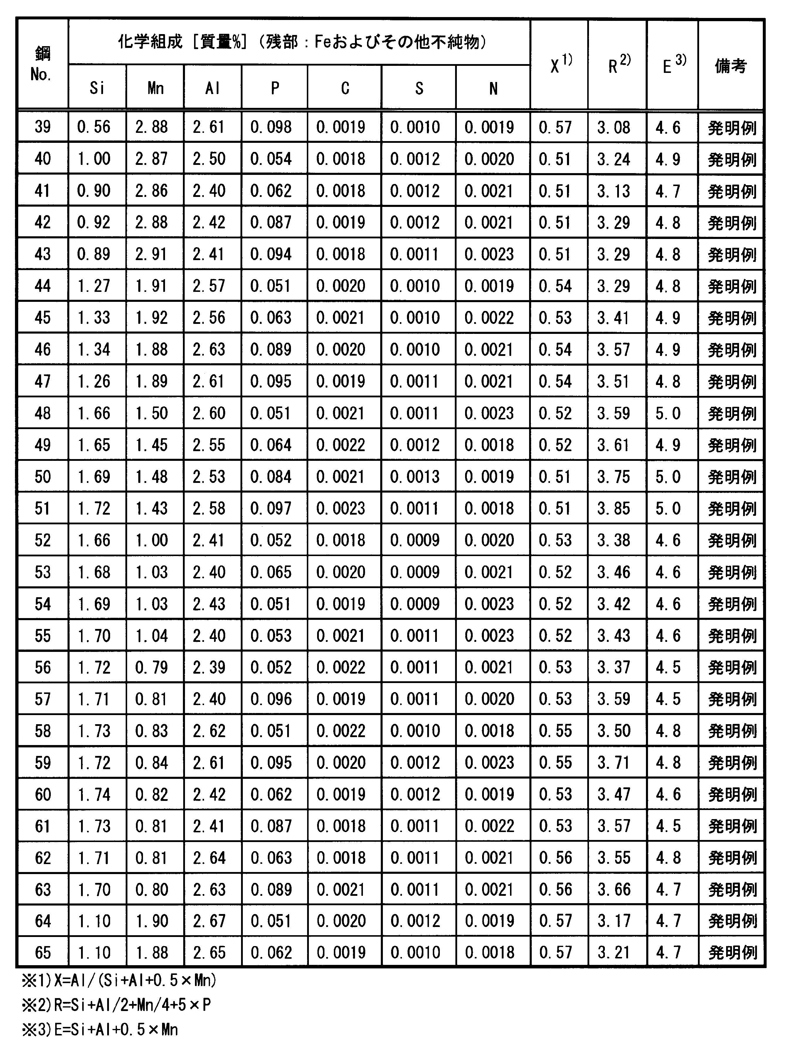
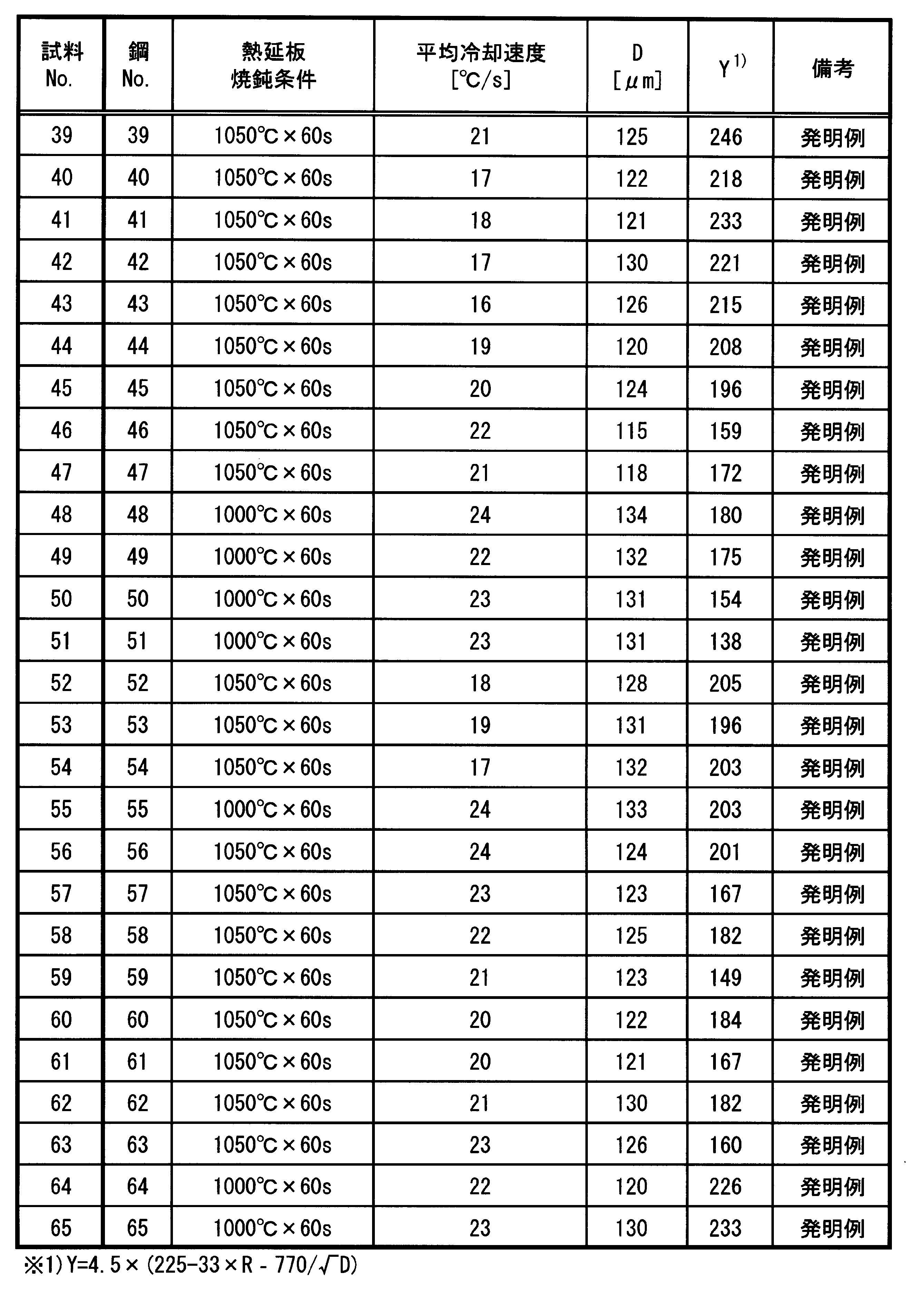
- Example 2 Steel No. having the chemical composition shown in Tables 5 and 6 below. 11 to 65 were melted in a vacuum and cast to obtain a slab. This slab was hot-rolled to obtain a hot-rolled sheet having a thickness of 2.0 mm. Next, in hot-rolled sheet annealing, after heating the hot-rolled sheet to 1000 ° C., the temperature of the hot-rolled sheet is maintained at 1000 ° C. or 1050 ° C. for 60 s, and the average cooling rate from 950 ° C. to 600 ° C. is shown in Table 7 below. The hot-rolled sheet was cooled from 1000 ° C. to room temperature so that the values shown in FIGS. The average crystal grain size (average crystal grain size of the steel sheet immediately before cold rolling) D [ ⁇ m] of the hot-rolled sheet annealed plate was measured. The average crystal grain size D [ ⁇ m] is shown in Tables 7 and 8.
- the hot-rolled sheet annealed sheet was cold-rolled to obtain a cold-rolled sheet having a thickness of 0.35 mm.
- the number of passes in this cold rolling was 6 passes.
- the rolling reduction in the first pass was 20%
- the total rolling reduction from the first pass to the second pass was 50%
- the total rolling reduction was 82.5%.
- this cold-rolled sheet was heated to 600 ° C.
- the temperature of the cold-rolled sheet was maintained at 600 ° C. for 20 s
- the cold-rolled sheet was further heated to 1050 ° C.
- the heated cold-rolled sheet was held at 1050 ° C. for 1 s to obtain non-oriented electrical steel sheets (Sample Nos. 11 to 65).
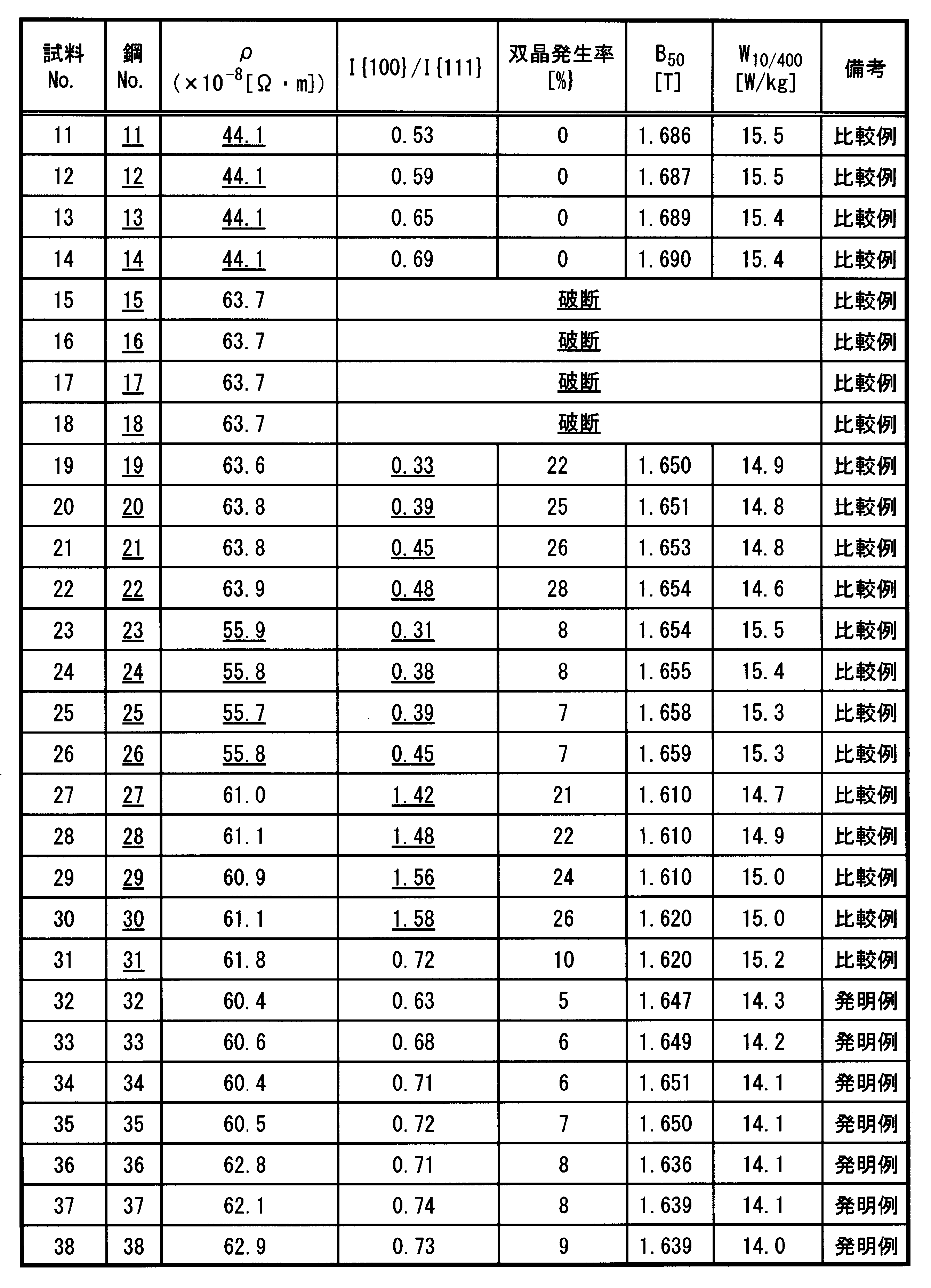
- a 55 mm square single plate test piece was punched from this non-oriented electrical steel sheet, and the specific resistance ⁇ [ ⁇ ⁇ m] at room temperature of this single plate test piece was measured. Further, the magnetic flux density B 50 [T] and W 10/400 [W / kg] at a magnetizing force of 5000 A / m of this single plate test piece were measured. Tables 9 and 10 show the results of ⁇ [ ⁇ ⁇ m], B 50 [T], and W 10/400 [W / kg]. In addition, any sample No. However, the average grain size of the non-oriented electrical steel sheet was about 100 ⁇ m.
- Sample No. In 11-14 the Si content, ⁇ and E were too small, so W 10/400 was high.
- Sample No. In 19-22 in addition to the Mn content being too high, X and I ⁇ 100 ⁇ / I ⁇ 111 ⁇ did not satisfy the above equations (12) and (18), respectively, so W 10/400 was high .
- Sample No. In 23-26 W 10/400 was high because the chemical composition and texture were inappropriate. These sample Nos. Then, in addition to the Mn content being too high and the Al content being too low, ⁇ was low and E was small.
- sample No. In 32 to 65, the chemical composition and production conditions of the steel were appropriate, so that the productivity (productivity and yield) in cold rolling was excellent. These sample Nos. Then, since the specific resistance and texture of the steel plate were appropriate, W 10/400 was low.
- FIG. 1 The graph showing the relationship between I ⁇ 100 ⁇ / I ⁇ 111 ⁇ and W 10/400 created from the data of 19-22 , 27-30 and 32-65 is shown. From FIG. 2, when I ⁇ 100 ⁇ / I ⁇ 111 ⁇ is in the range of 0.5 to 1.4, W 10/400 can be reduced to the minimum.
- an inexpensive non-oriented electrical steel sheet with further improved high-frequency iron loss and a method for producing the same can be provided, so that the industrial applicability of the present invention is great.
Landscapes
- Chemical & Material Sciences (AREA)
- Engineering & Computer Science (AREA)
- Mechanical Engineering (AREA)
- Organic Chemistry (AREA)
- Metallurgy (AREA)
- Materials Engineering (AREA)
- Physics & Mathematics (AREA)
- Crystallography & Structural Chemistry (AREA)
- Thermal Sciences (AREA)
- Manufacturing & Machinery (AREA)
- Electromagnetism (AREA)
- Dispersion Chemistry (AREA)
- Power Engineering (AREA)
- Manufacturing Of Steel Electrode Plates (AREA)
- Soft Magnetic Materials (AREA)
Abstract
Description
本願は、2015年3月17日に、日本に出願された特願2015-053095号に基づき優先権を主張し、その内容をここに援用する。
0.50≦Al/(Si+Al+0.5×Mn)≦0.83 (1)
1.28≦Si+Al/2+Mn/4+5×P≦3.90 (2)
4.0≦Si+Al+0.5×Mn≦7.0 (3)
0.50≦I{100}/I{111}≦1.40 (4)
0.50≦Al/(Si+Al+0.5×Mn)≦0.83 (5)
1.28≦Si+Al/2+Mn/4+5×P≦3.90 (6)
4.0≦Si+Al+0.5×Mn≦7.0 (7)
R=Si+Al/2+Mn/4+5×P (8)

以下、一実施形態に係る無方向性電磁鋼板における各構成について説明する。
まず、本実施形態に係る無方向性電磁鋼板の化学組成について述べる。以下において、各化学元素の含有量(%)は質量%で示されている。
Siは、鋼板の比抵抗を増加させて鋼板の鉄損を低減する。そのため、Si含有量が0.50%以上であることが必要である。また、Si含有量は、1.00%以上であると好ましく、1.20%以上であるとより好ましい。一方で、Si含有量が過剰であると冷間圧延時に鋼板が破断する恐れがある。また、本実施形態においては、後述のように、Si含有量を可能な限り低減してAl含有量を増加させている。さらには、Siは、鋼板のすべり系の活動を妨げるため、変形が生じた際に変形双晶の発達を促進する。この変形双晶は、磁壁の移動を妨げるので、打ち抜き後に変形双晶が多いと、ヒステリシス損が増加する。これらの観点から、Si含有量は、2.70%以下であることが必要である。また、Si含有量は、2.50%以下であると好ましく、2.00%以下であるとより好ましい。したがって、本実施形態の無方向性電磁鋼板のSi含有量は、0.50%~2.70%である。
Mnは、Sと結合してMnSになるため、Sによって鋼が脆化するのを防止する。そのため、Mn含有量は、0.10%以上であることが必要である。また、Mnは、Si、Alと同様に比抵抗を増加させて鋼板の鉄損を低減する。Mn含有量とSi含有量とが異なる同一比抵抗の2つの鋼を比較すると、Mn含有量が高い鋼の硬度は、Si含有量が高い鋼板の硬度よりも低い。よって、Mn含有量が高い鋼は、Si含有量が高い鋼と比べて冷間圧延時に破断が生じにくい。そのため、Mn含有量は、0.50%以上であると好ましく、1.00%以上であるとより好ましい。しかしながら、Mn含有量が過剰であると合金コストが増加する。この観点から、Mn含有量は、3.00%以下であることが必要である。また、Mn含有量は、2.50%以下であると好ましく、2.00%以下であるとより好ましい。したがって、本実施形態の無方向性電磁鋼板のMn含有量は、0.10%~3.00%である
Alは、SiおよびMnと同様に比抵抗を増加させて鋼板の鉄損を低減する。そして、Alが単位質量当たりの比抵抗の増加に及ぼす効果は、Siとほぼ同等であるが、Alが単位質量当たりの硬度上昇に及ぼす効果は、Siの約1/3~1/2である。よって、Alの含有量を増やすことによって高い生産性と高い比抵抗との両方を達成することができるため、Alは、本実施形態において重要な元素である。そのため、Al含有量は、1.00%以上であることが必要である。また、Al含有量は、1.50%以上であると好ましく、1.60%以上であるとより好ましい。一方で、Al含有量が過剰であると、飽和磁束密度が減少し、同一励磁条件における磁束密度も低下する。この観点から、Al含有量は、2.70%以下であることが必要である。また、Al含有量は、2.50%以下であると好ましく、2.40%以下であるとより好ましい。したがって、本実施形態の無方向性電磁鋼板のAl含有量は、1.00%~2.70%である。
Pは、無方向性電磁鋼板の集合組織を改善し、磁化を容易にする。また、Pは、打ち抜き時の加工性を改善する。そのため、P含有量は、0.050%以上であることが必要である。また、P含有量は、0.055%以上であると好ましく、0.060%以上であるとより好ましい。しかしながら、Si含有量とMn含有量とAl含有量との総量が大きく、比抵抗が高い無方向性電磁鋼板では、P含有量が0.100%を超えると、冷間圧延時に破断を生じる可能性がある。この観点から、P含有量は0.100%以下であることが必要である。また、P含有量は、0.090%以下であると好ましく、0.080%以下であるとより好ましい。したがって、本実施形態の無方向性電磁鋼板のP含有量は、0.050%~0.100%である。
残部はFeおよび不純物である。
本実施形態では、鋼板の比抵抗の変化量は、(Si+Al+0.5×Mn)の値にほぼ比例し、Al/(Si+Al+0.5×Mn)は、3つの化学元素(Si、Al、Mn)が比抵抗に及ぼす効果に占めるAlが比抵抗に及ぼす効果の比率を示す。(Si+Al+0.5×Mn)の値を維持したままAl/(Si+Al+0.5×Mn)の値が増加すると、鋼板の比抵抗は同等のまま冷間圧延の負荷を減らしたり冷間圧延時の鋼板の破断を防止したりすることができる。そのため、本実施形態では、Al/(Si+Al+0.5×Mn)は、0.50以上、すなわち、下記式(10)によって示される範囲である。この範囲では、Si含有量とAl含有量との総量に対するAl含有量の比率の増加に伴うヒステリシス損の増加によって、従来法においては鉄損が増加していた。一方で、本実施形態では、P含有量の範囲と集合組織とを制御することにより下記式(10)によって示される範囲内でも鉄損を維持もしくは低下させることができる。また、本実施形態では、Si含有量、Al含有量及びMn含有量が上述の範囲内であることが必要であるため、Al/(Si+Al+0.5×Mn)は、0.83以下、すなわち、下記式(11)によって示される範囲である。したがって、本実施形態では、Al/(Si+Al+0.5×Mn)は、下記式(12)を満足する。また、Al/(Si+Al+0.5×Mn)は、0.51以上であってもよく、0.80以下であってもよい。なお、以下では、下記式(13)で示されるように、Al/(Si+Al+0.5×Mn)をXと表現することもある。
Al/(Si+Al+0.5×Mn)≦0.83 (11)
0.50≦Al/(Si+Al+0.5×Mn)≦0.83 (12)
X=Al/(Si+Al+0.5×Mn) (13)
ここで、式中の各元素記号は鋼中の各元素の含有量(質量%)を示す。
Si、Al、Mn、およびPは、固溶強化能が高く、鋼板がこれら化学元素を過剰に含有すると冷間圧延中に鋼板が破断する恐れがある。そこで、下記式(14)に示すように、Si、Al、Mn、およびPの固溶強化能を表す指標として、固溶強化パラメータRを定義し、本実施形態では、この固溶強化パラメータRを3.90以下とする。また、本実施形態では、Si含有量、Al含有量、Mn含有量、およびP含有量が上述した範囲内であることが必要であるため、固溶強化パラメータRは、1.28以上である。したがって、固溶強化パラメータRは、下記式(15)に示すように、1.28~3.90である。また、固溶強化パラメータRは、1.50以上もしくは2.00以上であってもよく、3.80以下であってもよい。
1.28≦R≦3.90 (15)
ここで、式中の各元素記号は鋼中の各元素の含有量(質量%)を示す。
室温における比抵抗は、主にSi含有量、Al含有量、およびMn含有量によって定まる。高周波において低鉄損を確保する観点から、室温における比抵抗は60.0×10⁻⁸Ω・m以上であることが必要である。また、室温における比抵抗は、65.0×10⁻⁸Ω・m以上とすると好ましい。室温における比抵抗は、85.0×10⁻⁸Ω・m以下もしくは70.0×10⁻⁸Ω・m以下であってもよい。
なお、室温における比抵抗は公知の四端子法により測定する。鋼板のエッジから10cm以上離れた位置から少なくとも1つ試料を採取し、この試料から絶縁コーティングを除去してから比抵抗を測定する。絶縁コーティングの除去には、例えば20%の水酸化ナトリウム水溶液などのようなアルカリ水溶液を用いればよい。
4.0≦Si+Al+0.5×Mn≦7.0 (16)
E=Si+Al+0.5×Mn (17)
ここで、式中の各元素記号は鋼中の各元素の含有量(質量%)を示す。
無方向性電磁鋼板の平均結晶粒径(結晶粒の平均直径)は、30μm~200μmの範囲内であることが好ましい。平均結晶粒径が30μm以上であると、個々の再結晶粒の磁気特性が高いため、磁束密度及び鉄損が改善する。また、平均結晶粒径が200μm以下であると、渦電流損が減少し、さらに鉄損が低減する。
本実施形態に係る無方向性電磁鋼板は、下記式(18)に示すように、{111}面の強度I{111}に対する{100}面の強度I{100}の比率(I{100}/I{111})が0.50~1.40である集合組織を有する。図2に示すように、I{100}/I{111}が0.50未満であると、望ましい磁気特性が得られず、鉄損が増加する。一方、I{100}/I{111}が1.40を超えると、打ち抜き時に変形双晶が生じる結晶粒が著しく増加する。この変形双晶は、磁壁の移動を妨害するため、図2に示すように鉄損が劣化する。試料は、鋼板のエッジから10cm以上離れた位置から3つ採取する。これら試料の横断面(厚さ方向に垂直な断面)に対してエックス線回折法(反射法)を適用する。なお、測定する板厚位置(横断面の厚さ方向における位置)は、表面近傍(鋼板の表面から板厚の1/10の距離だけ離れた個所)及び板厚中心(鋼板の表面から板厚の1/2の距離だけ離れた個所)である。これら表面近傍と板厚中心との両方に対し、エックス線回折装置(エックス線回折法)を用いて反射法により3つの正極点図({200}面、{110}面、{211}面の正極点図)を測定する。これらの正極点図から計算により各板厚位置における結晶方位分布関数(ODF)を得る。その後、表面近傍のODFと板厚中心のODFとを平均化し、I{100}及びI{111}を決定する。
0.50≦I{100}/I{111}≦1.40 (18)
本実施形態では、本質的に高周波において低鉄損を達成することを前提としている。板厚が薄いと高周波において低鉄損を得ることができるため、板厚は0.40mm以下であることが必要である。また、板厚は、好ましくは0.30mm以下、より好ましくは0.20mm以下である。一方、板厚を過度に薄くすると鋼板の平坦度が劣化して鋼板の占積率が極端に低下したり、鉄心の生産性が低下したりする場合がある。そのため、板厚は0.05mm以上であることが必要である。また、板厚は、好ましくは0.10mm以上、より好ましくは0.15mm以上である。
本実施形態に係る無方向性電磁鋼板は、製造コストを低減する観点から下記実施形態に係る無方向性電磁鋼板の製造方法により製造することが好適である。
次に、一実施形態に係る無方向性電磁鋼板の製造方法における各工程について説明する。
熱間圧延工程においては、上述の化学組成を有するスラブに、熱間圧延を施して熱延板とする。
冷間圧延工程においては、上記熱間圧延工程後、熱延板に冷間圧延を施して冷延板とする。

仕上焼鈍工程においては、上記冷間圧延工程後、冷延板に仕上焼鈍を施して無方向性電磁鋼板とする。
本実施形態では、熱間圧延工程と冷間圧延工程との間に熱延板焼鈍工程を行ってもよい。熱延板焼鈍工程では、Al含有量が1.0%以上である鋼板の集合組織にPが与える効果をさらに高めることができ、高い磁束密度と低鉄損とをより安定的に確保できる。また、熱延板焼鈍工程では、熱間圧延時に導入された加工組織中の歪を解放し、熱延板の硬度を低下させる。そのため、熱延板焼鈍により、冷間圧延機への負荷を低減したり冷間圧延時の鋼板への損傷(例えば、リジングの発生)を低減したりできる。したがって、上記熱間圧延工程により得られた熱延板に熱延板焼鈍を施す熱延板焼鈍工程を行うことが好ましい。
下記表1に示す化学組成を有する鋼No.1~10を真空中で溶解し、鋳造してスラブを得た。このスラブを熱間圧延し2.0mmの板厚を有する熱延板を得た。次に、熱延板焼鈍において、この熱延板を1000℃まで加熱後、熱延板の温度を1000℃で60s保持し、950℃から600℃までの平均冷却速度が下記表2に示す値になるように熱延板を1000℃から室温まで冷却した。熱延板焼鈍後、熱延板を冷間圧延し、0.35mmの板厚を有する冷延板を得た。この冷延板の温度を1050℃で1s保持する仕上焼鈍を冷延板に対して施し、無方向性電磁鋼板(試料No.1~10)を得た。


上記表1に示した鋼No.1、3、4、5、7、および8を真空中で溶解し、鋳造してスラブを得た。このスラブを熱間圧延し2.0mmの板厚を有する熱延板を得た。次に、熱延板焼鈍において、この熱延板を下記表3に示す焼鈍温度まで加熱後、熱延板の温度をその温度に60s保持し、950℃から600℃までの平均冷却速度が下記表3に示す値になるように熱延板をその保持温度から室温まで冷却した。

上記表1に示した鋼No.6、7、及び8を真空中で溶解し、鋳造してスラブを得た。このスラブを熱間圧延し2.0mmの板厚を有する熱延板を得た。次に、熱延板焼鈍において、この熱延板を1000℃まで加熱後、熱延板の温度を1000℃に60s間保持し、950℃から600℃までの平均冷却速度が1℃/s~30℃/sになるように熱延板を1000℃から室温まで冷却した。その後、熱延板焼鈍板を冷間圧延して板厚0.35mmの冷延板を得た。引き続き、仕上焼鈍では、冷延板を1050℃まで加熱し、冷延板の温度を1050℃で1s保持した後、冷延板を1050℃から室温まで冷却して、無方向性電磁鋼板(試料No.6-e~8-f)を得た。試料No.6-f、7-f、8-fでは、表4に示すように、冷延板の温度を1050℃まで加熱する加熱過程において、冷延板の温度を600℃で20s間保持した。

下記表5及び6に示す化学組成を有する鋼No.11~65を真空中で溶解し、鋳造してスラブを得た。このスラブを熱間圧延し2.0mmの板厚を有する熱延板を得た。次に、熱延板焼鈍において、この熱延板を1000℃まで加熱後、熱延板の温度を1000℃または1050℃で60s保持し、950℃から600℃までの平均冷却速度が下記表7及び8に示す値になるように熱延板を1000℃から室温まで冷却した。この熱延板焼鈍板の平均結晶粒径(冷間圧延直前の鋼板の平均結晶粒径)D[μm]を測定した。平均結晶粒径D[μm]を表7及び8に示す。



Claims (3)
- 質量%で、
C:0%~0.0050%、
Si:0.50%~2.70%、
Mn:0.10%~3.00%、
Al:1.00%~2.70%、
P:0.050%~0.100%、
S:0%~0.0060%、
N:0%~0.0050%、
Ti:0%~0.008%、
V:0%~0.008%、
Nb:0%~0.008%、
Zr:0%~0.008%、
を含有し、残部がFeおよび不純物からなる化学組成を有し、
前記化学組成が下記式(1)、下記式(2)及び下記式(3)を満足し、
エックス線回折法により測定した正極点図から表面近傍の結晶方位分布関数と板厚中心の結晶方位分布関数との平均を得て決定される、{100}面の強度I{100}と{111}面の強度I{111}とが下記式(4)を満足し、
室温における比抵抗が60.0×10⁻⁸Ω・m以上であり、
板厚が0.05mm~0.40mmである
ことを特徴とする無方向性電磁鋼板。
0.50≦Al/(Si+Al+0.5×Mn)≦0.83 (1)
1.28≦Si+Al/2+Mn/4+5×P≦3.90 (2)
4.0≦Si+Al+0.5×Mn≦7.0 (3)
0.50≦I{100}/I{111}≦1.40 (4) - 質量%で、
C:0%~0.0050%、
Si:0.50%~2.70%、
Mn:0.10%~3.00%、
Al:1.00%~2.70%、
P:0.050%~0.100%、
S:0%~0.0060%、
N:0%~0.0050%、
Ti:0%~0.008%、
V:0%~0.008%、
Nb:0%~0.008%、
Zr:0%~0.008%、
を含有し、残部がFeおよび不純物からなる化学組成を有し、前記化学組成が下記式(5)、下記式(6)及び下記式(7)を満足するスラブに、熱間圧延を施して熱延板を製造する熱間圧延工程と、
前記熱間圧延工程後に、前記熱延板に冷間圧延を施して0.05mm~0.40mmの板厚を有する冷延板を製造する冷間圧延工程と、
前記冷間圧延工程後に、前記冷延板に仕上焼鈍を施す仕上焼鈍工程と
を有し、
前記冷間圧延工程では、前記冷間圧延の前に前記熱延板の平均結晶粒径D(μm)と下記式(8)で表される固溶強化パラメータRとが下記式(9)を満足し、
前記仕上焼鈍工程で前記冷延板を加熱する過程では、前記冷延板の温度を550℃~700℃の範囲内の一定温度で10~300s保つ
ことを特徴とする無方向性電磁鋼板の製造方法。
0.50≦Al/(Si+Al+0.5×Mn)≦0.83 (5)
1.28≦Si+Al/2+Mn/4+5×P≦3.90 (6)
4.0≦Si+Al+0.5×Mn≦7.0 (7)
R=Si+Al/2+Mn/4+5×P (8)

- 前記熱間圧延工程と前記冷間圧延工程との間に、前記熱延板に熱延板焼鈍を施す熱延板焼鈍工程をさらに有することを特徴とする請求項2に記載の無方向性電磁鋼板の製造方法。
Priority Applications (7)
| Application Number | Priority Date | Filing Date | Title |
|---|---|---|---|
| JP2017506496A JP6451832B2 (ja) | 2015-03-17 | 2016-03-10 | 無方向性電磁鋼板およびその製造方法 |
| CN201680007502.4A CN107208220B (zh) | 2015-03-17 | 2016-03-10 | 无方向性电磁钢板以及其制造方法 |
| PL16764840T PL3272894T3 (pl) | 2015-03-17 | 2016-03-10 | Blacha cienka z niezorientowanej stali elektrotechnicznej oraz sposób jej wytwarzania |
| KR1020177020820A KR101961057B1 (ko) | 2015-03-17 | 2016-03-10 | 무방향성 전자 강판 및 그 제조 방법 |
| US15/541,932 US11396681B2 (en) | 2015-03-17 | 2016-03-10 | Non-oriented electrical steel sheet and method for manufacturing thereof |
| EP16764840.1A EP3272894B1 (en) | 2015-03-17 | 2016-03-10 | Non-oriented electromagnetic steel sheet and method for manufacturing same |
| BR112017014208-2A BR112017014208B1 (pt) | 2015-03-17 | 2016-03-10 | Chapa de aço elétrico não-orientado e método para fabricação da mesma |
Applications Claiming Priority (2)
| Application Number | Priority Date | Filing Date | Title |
|---|---|---|---|
| JP2015053095 | 2015-03-17 | ||
| JP2015-053095 | 2015-03-17 |
Publications (1)
| Publication Number | Publication Date |
|---|---|
| WO2016148010A1 true WO2016148010A1 (ja) | 2016-09-22 |
Family
ID=56919197
Family Applications (1)
| Application Number | Title | Priority Date | Filing Date |
|---|---|---|---|
| PCT/JP2016/057572 Ceased WO2016148010A1 (ja) | 2015-03-17 | 2016-03-10 | 無方向性電磁鋼板およびその製造方法 |
Country Status (9)
| Country | Link |
|---|---|
| US (1) | US11396681B2 (ja) |
| EP (1) | EP3272894B1 (ja) |
| JP (1) | JP6451832B2 (ja) |
| KR (1) | KR101961057B1 (ja) |
| CN (1) | CN107208220B (ja) |
| BR (1) | BR112017014208B1 (ja) |
| PL (1) | PL3272894T3 (ja) |
| TW (1) | TWI604069B (ja) |
| WO (1) | WO2016148010A1 (ja) |
Cited By (5)
| Publication number | Priority date | Publication date | Assignee | Title |
|---|---|---|---|---|
| WO2022196800A1 (ja) | 2021-03-19 | 2022-09-22 | 日本製鉄株式会社 | 無方向性電磁鋼板およびその製造方法 |
| WO2022196807A1 (ja) | 2021-03-19 | 2022-09-22 | 日本製鉄株式会社 | 無方向性電磁鋼板およびその製造方法 |
| WO2022196805A1 (ja) | 2021-03-19 | 2022-09-22 | 日本製鉄株式会社 | 無方向性電磁鋼板およびその製造方法 |
| US11566303B2 (en) | 2018-02-16 | 2023-01-31 | Nippon Steel Corporation | Non-oriented electrical steel sheet and method for manufacturing non-oriented electrical steel sheet |
| WO2024150732A1 (ja) | 2023-01-10 | 2024-07-18 | 日本製鉄株式会社 | 無方向性電磁鋼板 |
Families Citing this family (10)
| Publication number | Priority date | Publication date | Assignee | Title |
|---|---|---|---|---|
| PL3570305T3 (pl) | 2017-01-10 | 2025-03-31 | Nippon Steel Corporation | Nawijany rdzeń i sposób wytwarzania |
| DE102017208146B4 (de) * | 2017-05-15 | 2019-06-19 | Thyssenkrupp Ag | NO-Elektroband für E-Motoren |
| WO2018220839A1 (ja) | 2017-06-02 | 2018-12-06 | 新日鐵住金株式会社 | 無方向性電磁鋼板 |
| TWI643962B (zh) * | 2017-06-07 | 2018-12-11 | 日商新日鐵住金股份有限公司 | Non-directional electromagnetic steel sheet |
| JP7010359B2 (ja) | 2018-02-16 | 2022-01-26 | 日本製鉄株式会社 | 無方向性電磁鋼板、及び無方向性電磁鋼板の製造方法 |
| WO2020094230A1 (de) | 2018-11-08 | 2020-05-14 | Thyssenkrupp Steel Europe Ag | Elektroband oder -blech für höherfrequente elektromotoranwendungen mit verbesserter polarisation und geringen ummagnetisierungsverlusten |
| EP4317474A4 (en) * | 2021-03-31 | 2024-12-04 | Nippon Steel Corporation | NON-ORIENTED ELECTROMAGNETIC STEEL SHEET |
| CN114713780B (zh) * | 2022-03-31 | 2024-03-22 | 江苏沙钢集团有限公司 | 一种提高硅钢钢水在薄带连铸工艺下凝固成带稳定性的方法 |
| EP4685259A1 (en) * | 2023-04-13 | 2026-01-28 | JFE Steel Corporation | Non-oriented electromagnetic steel sheet |
| CN120936738A (zh) * | 2023-04-13 | 2025-11-11 | 杰富意钢铁株式会社 | 无取向性电磁钢板 |
Citations (2)
| Publication number | Priority date | Publication date | Assignee | Title |
|---|---|---|---|---|
| JP2001158948A (ja) * | 1999-12-01 | 2001-06-12 | Kawasaki Steel Corp | 鉄損の低い無方向性電磁鋼板およびその製造方法 |
| JP2001200347A (ja) * | 2000-01-20 | 2001-07-24 | Kawasaki Steel Corp | 鉄損の低い無方向性電磁鋼板およびその製造方法 |
Family Cites Families (21)
| Publication number | Priority date | Publication date | Assignee | Title |
|---|---|---|---|---|
| JP2001181806A (ja) * | 1999-10-13 | 2001-07-03 | Nippon Steel Corp | 透磁率に優れた無方向性電磁鋼板とその熱延板およびその製造方法 |
| JP4023183B2 (ja) | 2002-02-26 | 2007-12-19 | 住友金属工業株式会社 | 回転機用無方向性電磁鋼板とその製造方法 |
| JP2005200756A (ja) | 2004-01-19 | 2005-07-28 | Sumitomo Metal Ind Ltd | 無方向性電磁鋼板の製造方法 |
| CN101218362B (zh) * | 2005-07-07 | 2010-05-12 | 住友金属工业株式会社 | 无方向性电磁钢板及其制造方法 |
| JP4658840B2 (ja) | 2006-03-20 | 2011-03-23 | 新日本製鐵株式会社 | 無方向性電磁鋼板の製造方法 |
| JPWO2007144964A1 (ja) | 2006-06-16 | 2009-10-29 | 新日本製鐵株式会社 | 高強度電磁鋼板およびその製造方法 |
| KR20100122116A (ko) * | 2008-04-14 | 2010-11-19 | 신닛뽄세이테쯔 카부시키카이샤 | 고강도 무방향성 전자기 강판 및 그 제조 방법 |
| JP5126788B2 (ja) * | 2008-07-30 | 2013-01-23 | 新日鐵住金株式会社 | 回転子用無方向性電磁鋼板およびその製造方法 |
| CN102459675B (zh) * | 2009-06-03 | 2016-06-01 | 新日铁住金株式会社 | 无方向性电磁钢板及其制造方法 |
| KR101296114B1 (ko) * | 2009-12-28 | 2013-08-19 | 주식회사 포스코 | 자성이 우수한 무방향성 전기강판 및 그 제조방법 |
| KR101286243B1 (ko) * | 2009-12-28 | 2013-07-15 | 주식회사 포스코 | 자성이 우수한 무방향성 전기강판 및 그 제조방법 |
| US20120267015A1 (en) * | 2009-12-28 | 2012-10-25 | Posco | Non-Oriented Electrical Steel Sheet Having Superior Magnetic Properties and a Production Method Therefor |
| MX2013009670A (es) * | 2011-02-24 | 2013-10-28 | Jfe Steel Corp | Lamina de acero electrico no orientado y metodo para fabricar la misma. |
| JP5780013B2 (ja) * | 2011-06-28 | 2015-09-16 | Jfeスチール株式会社 | 無方向性電磁鋼板の製造方法 |
| JP5972540B2 (ja) | 2011-08-23 | 2016-08-17 | 新日鐵住金株式会社 | 無方向性電磁鋼板 |
| JP5712863B2 (ja) | 2011-08-23 | 2015-05-07 | 新日鐵住金株式会社 | 無方向性電磁鋼板の製造方法 |
| JP5605518B2 (ja) | 2011-11-11 | 2014-10-15 | 新日鐵住金株式会社 | 無方向性電磁鋼板およびその製造方法 |
| US8840734B2 (en) * | 2012-02-14 | 2014-09-23 | Nippon Steel & Sumitomo Metal Corporation | Non-oriented electrical steel sheet |
| JP5892327B2 (ja) | 2012-03-15 | 2016-03-23 | Jfeスチール株式会社 | 無方向性電磁鋼板の製造方法 |
| US9570219B2 (en) | 2012-03-29 | 2017-02-14 | Nippon Steel & Sumitomo Metal Corporation | Non-oriented electrical steel sheet and method of manufacturing non-oriented electrical steel sheet |
| JP5648661B2 (ja) | 2012-09-13 | 2015-01-07 | 新日鐵住金株式会社 | 時効熱処理用無方向性電磁鋼板ならびに無方向性電磁鋼板およびその製造方法 |
-
2016
- 2016-03-10 JP JP2017506496A patent/JP6451832B2/ja active Active
- 2016-03-10 BR BR112017014208-2A patent/BR112017014208B1/pt active IP Right Grant
- 2016-03-10 CN CN201680007502.4A patent/CN107208220B/zh active Active
- 2016-03-10 PL PL16764840T patent/PL3272894T3/pl unknown
- 2016-03-10 EP EP16764840.1A patent/EP3272894B1/en active Active
- 2016-03-10 WO PCT/JP2016/057572 patent/WO2016148010A1/ja not_active Ceased
- 2016-03-10 US US15/541,932 patent/US11396681B2/en active Active
- 2016-03-10 KR KR1020177020820A patent/KR101961057B1/ko active Active
- 2016-03-14 TW TW105107783A patent/TWI604069B/zh active
Patent Citations (2)
| Publication number | Priority date | Publication date | Assignee | Title |
|---|---|---|---|---|
| JP2001158948A (ja) * | 1999-12-01 | 2001-06-12 | Kawasaki Steel Corp | 鉄損の低い無方向性電磁鋼板およびその製造方法 |
| JP2001200347A (ja) * | 2000-01-20 | 2001-07-24 | Kawasaki Steel Corp | 鉄損の低い無方向性電磁鋼板およびその製造方法 |
Non-Patent Citations (1)
| Title |
|---|
| See also references of EP3272894A4 * |
Cited By (10)
| Publication number | Priority date | Publication date | Assignee | Title |
|---|---|---|---|---|
| US11566303B2 (en) | 2018-02-16 | 2023-01-31 | Nippon Steel Corporation | Non-oriented electrical steel sheet and method for manufacturing non-oriented electrical steel sheet |
| WO2022196800A1 (ja) | 2021-03-19 | 2022-09-22 | 日本製鉄株式会社 | 無方向性電磁鋼板およびその製造方法 |
| WO2022196807A1 (ja) | 2021-03-19 | 2022-09-22 | 日本製鉄株式会社 | 無方向性電磁鋼板およびその製造方法 |
| WO2022196805A1 (ja) | 2021-03-19 | 2022-09-22 | 日本製鉄株式会社 | 無方向性電磁鋼板およびその製造方法 |
| KR20230142784A (ko) | 2021-03-19 | 2023-10-11 | 닛폰세이테츠 가부시키가이샤 | 무방향성 전자 강판 및 그 제조 방법 |
| KR20230144606A (ko) | 2021-03-19 | 2023-10-16 | 닛폰세이테츠 가부시키가이샤 | 무방향성 전자 강판 및 그 제조 방법 |
| KR20230145142A (ko) | 2021-03-19 | 2023-10-17 | 닛폰세이테츠 가부시키가이샤 | 무방향성 전자 강판 및 그 제조 방법 |
| WO2024150732A1 (ja) | 2023-01-10 | 2024-07-18 | 日本製鉄株式会社 | 無方向性電磁鋼板 |
| KR20250133748A (ko) | 2023-01-10 | 2025-09-08 | 닛폰세이테츠 가부시키가이샤 | 무방향성 전자 강판 |
| EP4650475A1 (en) | 2023-01-10 | 2025-11-19 | Nippon Steel Corporation | Non-oriented electromagnetic steel sheet |
Also Published As
| Publication number | Publication date |
|---|---|
| EP3272894A4 (en) | 2018-08-15 |
| JP6451832B2 (ja) | 2019-01-16 |
| JPWO2016148010A1 (ja) | 2017-11-02 |
| PL3272894T3 (pl) | 2019-12-31 |
| EP3272894B1 (en) | 2019-06-19 |
| KR101961057B1 (ko) | 2019-03-21 |
| TWI604069B (zh) | 2017-11-01 |
| BR112017014208B1 (pt) | 2021-08-03 |
| US20180002776A1 (en) | 2018-01-04 |
| CN107208220A (zh) | 2017-09-26 |
| BR112017014208A2 (ja) | 2018-03-06 |
| EP3272894A1 (en) | 2018-01-24 |
| TW201641710A (zh) | 2016-12-01 |
| KR20170100004A (ko) | 2017-09-01 |
| CN107208220B (zh) | 2019-03-01 |
| US11396681B2 (en) | 2022-07-26 |
Similar Documents
| Publication | Publication Date | Title |
|---|---|---|
| JP6451832B2 (ja) | 無方向性電磁鋼板およびその製造方法 | |
| TWI658152B (zh) | 無方向性電磁鋼板及無方向性電磁鋼板之製造方法 | |
| EP3859032A1 (en) | Non-oriented electromagnetic steel sheet and method for manufacturing same, and motor core and method for manufacturing same | |
| JP5601078B2 (ja) | 無方向性電磁鋼板およびその製造方法 | |
| KR102656381B1 (ko) | 무방향성 전자기 강판 | |
| WO2020091039A1 (ja) | 無方向性電磁鋼板 | |
| CN104520458B (zh) | 高强度电磁钢板及其制造方法 | |
| TWI829403B (zh) | 無方向性電磁鋼板及其製造方法 | |
| JP5716811B2 (ja) | 無方向性電磁鋼板の製造方法 | |
| JP2019183185A (ja) | 無方向性電磁鋼板 | |
| JP2015516503A (ja) | 無方向性電磁鋼板及びその製造方法 | |
| KR20240021880A (ko) | 무방향성 전자 강판과 그의 제조 방법 | |
| KR102706290B1 (ko) | 무방향성 전자 강판 및 그 제조 방법 | |
| JP6638359B2 (ja) | 無方向性電磁鋼板およびその製造方法 | |
| WO2024080140A1 (ja) | 無方向性電磁鋼板とその製造方法 | |
| JP4855221B2 (ja) | 分割コア用無方向性電磁鋼板 | |
| KR102961099B1 (ko) | 무방향성 전자 강판과 그의 제조 방법 | |
| CN117545868B (en) | Non-oriented electromagnetic steel sheet and method for producing same | |
| KR20240027787A (ko) | 무방향성 전자 강판과 그의 제조 방법 | |
| KR20250133748A (ko) | 무방향성 전자 강판 | |
| JP6780246B2 (ja) | 無方向性電磁鋼板、およびその製造方法 | |
| JP4192332B2 (ja) | 一方向性電磁鋼板の製造方法 |
Legal Events
| Date | Code | Title | Description |
|---|---|---|---|
| 121 | Ep: the epo has been informed by wipo that ep was designated in this application |
Ref document number: 16764840 Country of ref document: EP Kind code of ref document: A1 |
|
| ENP | Entry into the national phase |
Ref document number: 2017506496 Country of ref document: JP Kind code of ref document: A |
|
| REEP | Request for entry into the european phase |
Ref document number: 2016764840 Country of ref document: EP |
|
| WWE | Wipo information: entry into national phase |
Ref document number: 15541932 Country of ref document: US |
|
| REG | Reference to national code |
Ref country code: BR Ref legal event code: B01A Ref document number: 112017014208 Country of ref document: BR |
|
| ENP | Entry into the national phase |
Ref document number: 20177020820 Country of ref document: KR Kind code of ref document: A |
|
| NENP | Non-entry into the national phase |
Ref country code: DE |
|
| ENP | Entry into the national phase |
Ref document number: 112017014208 Country of ref document: BR Kind code of ref document: A2 Effective date: 20170629 |