WO2016151713A1 - 加工ノズル、加工ヘッド、加工装置、加工ノズルの制御方法および制御プログラム - Google Patents
加工ノズル、加工ヘッド、加工装置、加工ノズルの制御方法および制御プログラム Download PDFInfo
- Publication number
- WO2016151713A1 WO2016151713A1 PCT/JP2015/058627 JP2015058627W WO2016151713A1 WO 2016151713 A1 WO2016151713 A1 WO 2016151713A1 JP 2015058627 W JP2015058627 W JP 2015058627W WO 2016151713 A1 WO2016151713 A1 WO 2016151713A1
- Authority
- WO
- WIPO (PCT)
- Prior art keywords
- processing
- powder
- molten pool
- nozzle
- shape
- Prior art date
- Legal status (The legal status is an assumption and is not a legal conclusion. Google has not performed a legal analysis and makes no representation as to the accuracy of the status listed.)
- Ceased
Links
Images


Classifications
-
- B—PERFORMING OPERATIONS; TRANSPORTING
- B23—MACHINE TOOLS; METAL-WORKING NOT OTHERWISE PROVIDED FOR
- B23K—SOLDERING OR UNSOLDERING; WELDING; CLADDING OR PLATING BY SOLDERING OR WELDING; CUTTING BY APPLYING HEAT LOCALLY, e.g. FLAME CUTTING; WORKING BY LASER BEAM
- B23K26/00—Working by laser beam, e.g. welding, cutting or boring
- B23K26/14—Working by laser beam, e.g. welding, cutting or boring using a fluid stream, e.g. a jet of gas, in conjunction with the laser beam; Nozzles therefor
- B23K26/144—Working by laser beam, e.g. welding, cutting or boring using a fluid stream, e.g. a jet of gas, in conjunction with the laser beam; Nozzles therefor the fluid stream containing particles, e.g. powder
-
- B—PERFORMING OPERATIONS; TRANSPORTING
- B33—ADDITIVE MANUFACTURING TECHNOLOGY
- B33Y—ADDITIVE MANUFACTURING, i.e. MANUFACTURING OF THREE-DIMENSIONAL [3D] OBJECTS BY ADDITIVE DEPOSITION, ADDITIVE AGGLOMERATION OR ADDITIVE LAYERING, e.g. BY 3D PRINTING, STEREOLITHOGRAPHY OR SELECTIVE LASER SINTERING
- B33Y30/00—Apparatus for additive manufacturing; Details thereof or accessories therefor
-
- B—PERFORMING OPERATIONS; TRANSPORTING
- B22—CASTING; POWDER METALLURGY
- B22F—WORKING METALLIC POWDER; MANUFACTURE OF ARTICLES FROM METALLIC POWDER; MAKING METALLIC POWDER; APPARATUS OR DEVICES SPECIALLY ADAPTED FOR METALLIC POWDER
- B22F10/00—Additive manufacturing of workpieces or articles from metallic powder
- B22F10/20—Direct sintering or melting
- B22F10/25—Direct deposition of metal particles, e.g. direct metal deposition [DMD] or laser engineered net shaping [LENS]
-
- B—PERFORMING OPERATIONS; TRANSPORTING
- B22—CASTING; POWDER METALLURGY
- B22F—WORKING METALLIC POWDER; MANUFACTURE OF ARTICLES FROM METALLIC POWDER; MAKING METALLIC POWDER; APPARATUS OR DEVICES SPECIALLY ADAPTED FOR METALLIC POWDER
- B22F12/00—Apparatus or devices specially adapted for additive manufacturing; Auxiliary means for additive manufacturing; Combinations of additive manufacturing apparatus or devices with other processing apparatus or devices
- B22F12/50—Means for feeding of material, e.g. heads
- B22F12/53—Nozzles
-
- B—PERFORMING OPERATIONS; TRANSPORTING
- B22—CASTING; POWDER METALLURGY
- B22F—WORKING METALLIC POWDER; MANUFACTURE OF ARTICLES FROM METALLIC POWDER; MAKING METALLIC POWDER; APPARATUS OR DEVICES SPECIALLY ADAPTED FOR METALLIC POWDER
- B22F12/00—Apparatus or devices specially adapted for additive manufacturing; Auxiliary means for additive manufacturing; Combinations of additive manufacturing apparatus or devices with other processing apparatus or devices
- B22F12/50—Means for feeding of material, e.g. heads
- B22F12/57—Metering means
-
- B—PERFORMING OPERATIONS; TRANSPORTING
- B22—CASTING; POWDER METALLURGY
- B22F—WORKING METALLIC POWDER; MANUFACTURE OF ARTICLES FROM METALLIC POWDER; MAKING METALLIC POWDER; APPARATUS OR DEVICES SPECIALLY ADAPTED FOR METALLIC POWDER
- B22F12/00—Apparatus or devices specially adapted for additive manufacturing; Auxiliary means for additive manufacturing; Combinations of additive manufacturing apparatus or devices with other processing apparatus or devices
- B22F12/90—Means for process control, e.g. cameras or sensors
-
- B—PERFORMING OPERATIONS; TRANSPORTING
- B22—CASTING; POWDER METALLURGY
- B22F—WORKING METALLIC POWDER; MANUFACTURE OF ARTICLES FROM METALLIC POWDER; MAKING METALLIC POWDER; APPARATUS OR DEVICES SPECIALLY ADAPTED FOR METALLIC POWDER
- B22F3/00—Manufacture of workpieces or articles from metallic powder characterised by the manner of compacting or sintering; Apparatus specially adapted therefor ; Presses and furnaces
- B22F3/10—Sintering only
- B22F3/105—Sintering only by using electric current other than for infrared radiant energy, laser radiation or plasma ; by ultrasonic bonding
-
- B—PERFORMING OPERATIONS; TRANSPORTING
- B23—MACHINE TOOLS; METAL-WORKING NOT OTHERWISE PROVIDED FOR
- B23K—SOLDERING OR UNSOLDERING; WELDING; CLADDING OR PLATING BY SOLDERING OR WELDING; CUTTING BY APPLYING HEAT LOCALLY, e.g. FLAME CUTTING; WORKING BY LASER BEAM
- B23K26/00—Working by laser beam, e.g. welding, cutting or boring
- B23K26/02—Positioning or observing the workpiece, e.g. with respect to the point of impact; Aligning, aiming or focusing the laser beam
- B23K26/03—Observing, e.g. monitoring, the workpiece
- B23K26/032—Observing, e.g. monitoring, the workpiece using optical means
-
- B—PERFORMING OPERATIONS; TRANSPORTING
- B23—MACHINE TOOLS; METAL-WORKING NOT OTHERWISE PROVIDED FOR
- B23K—SOLDERING OR UNSOLDERING; WELDING; CLADDING OR PLATING BY SOLDERING OR WELDING; CUTTING BY APPLYING HEAT LOCALLY, e.g. FLAME CUTTING; WORKING BY LASER BEAM
- B23K26/00—Working by laser beam, e.g. welding, cutting or boring
- B23K26/02—Positioning or observing the workpiece, e.g. with respect to the point of impact; Aligning, aiming or focusing the laser beam
- B23K26/06—Shaping the laser beam, e.g. by masks or multi-focusing
- B23K26/0665—Shaping the laser beam, e.g. by masks or multi-focusing by beam condensation on the workpiece, e.g. for focusing
-
- B—PERFORMING OPERATIONS; TRANSPORTING
- B23—MACHINE TOOLS; METAL-WORKING NOT OTHERWISE PROVIDED FOR
- B23K—SOLDERING OR UNSOLDERING; WELDING; CLADDING OR PLATING BY SOLDERING OR WELDING; CUTTING BY APPLYING HEAT LOCALLY, e.g. FLAME CUTTING; WORKING BY LASER BEAM
- B23K26/00—Working by laser beam, e.g. welding, cutting or boring
- B23K26/70—Auxiliary operations or equipment
- B23K26/702—Auxiliary equipment
-
- B—PERFORMING OPERATIONS; TRANSPORTING
- B29—WORKING OF PLASTICS; WORKING OF SUBSTANCES IN A PLASTIC STATE IN GENERAL
- B29C—SHAPING OR JOINING OF PLASTICS; SHAPING OF MATERIAL IN A PLASTIC STATE, NOT OTHERWISE PROVIDED FOR; AFTER-TREATMENT OF THE SHAPED PRODUCTS, e.g. REPAIRING
- B29C35/00—Heating, cooling or curing, e.g. crosslinking or vulcanising; Apparatus therefor
- B29C35/02—Heating or curing, e.g. crosslinking or vulcanizing during moulding, e.g. in a mould
- B29C35/08—Heating or curing, e.g. crosslinking or vulcanizing during moulding, e.g. in a mould by wave energy or particle radiation
- B29C35/0805—Heating or curing, e.g. crosslinking or vulcanizing during moulding, e.g. in a mould by wave energy or particle radiation using electromagnetic radiation
-
- B—PERFORMING OPERATIONS; TRANSPORTING
- B29—WORKING OF PLASTICS; WORKING OF SUBSTANCES IN A PLASTIC STATE IN GENERAL
- B29C—SHAPING OR JOINING OF PLASTICS; SHAPING OF MATERIAL IN A PLASTIC STATE, NOT OTHERWISE PROVIDED FOR; AFTER-TREATMENT OF THE SHAPED PRODUCTS, e.g. REPAIRING
- B29C64/00—Additive manufacturing, i.e. manufacturing of three-dimensional [3D] objects by additive deposition, additive agglomeration or additive layering, e.g. by 3D printing, stereolithography or selective laser sintering
- B29C64/20—Apparatus for additive manufacturing; Details thereof or accessories therefor
- B29C64/205—Means for applying layers
- B29C64/209—Heads; Nozzles
-
- B—PERFORMING OPERATIONS; TRANSPORTING
- B29—WORKING OF PLASTICS; WORKING OF SUBSTANCES IN A PLASTIC STATE IN GENERAL
- B29C—SHAPING OR JOINING OF PLASTICS; SHAPING OF MATERIAL IN A PLASTIC STATE, NOT OTHERWISE PROVIDED FOR; AFTER-TREATMENT OF THE SHAPED PRODUCTS, e.g. REPAIRING
- B29C67/00—Shaping techniques not covered by groups B29C39/00 - B29C65/00, B29C70/00 or B29C73/00
-
- B—PERFORMING OPERATIONS; TRANSPORTING
- B22—CASTING; POWDER METALLURGY
- B22F—WORKING METALLIC POWDER; MANUFACTURE OF ARTICLES FROM METALLIC POWDER; MAKING METALLIC POWDER; APPARATUS OR DEVICES SPECIALLY ADAPTED FOR METALLIC POWDER
- B22F12/00—Apparatus or devices specially adapted for additive manufacturing; Auxiliary means for additive manufacturing; Combinations of additive manufacturing apparatus or devices with other processing apparatus or devices
- B22F12/30—Platforms or substrates
- B22F12/33—Platforms or substrates translatory in the deposition plane
-
- B—PERFORMING OPERATIONS; TRANSPORTING
- B22—CASTING; POWDER METALLURGY
- B22F—WORKING METALLIC POWDER; MANUFACTURE OF ARTICLES FROM METALLIC POWDER; MAKING METALLIC POWDER; APPARATUS OR DEVICES SPECIALLY ADAPTED FOR METALLIC POWDER
- B22F2999/00—Aspects linked to processes or compositions used in powder metallurgy
-
- B—PERFORMING OPERATIONS; TRANSPORTING
- B29—WORKING OF PLASTICS; WORKING OF SUBSTANCES IN A PLASTIC STATE IN GENERAL
- B29C—SHAPING OR JOINING OF PLASTICS; SHAPING OF MATERIAL IN A PLASTIC STATE, NOT OTHERWISE PROVIDED FOR; AFTER-TREATMENT OF THE SHAPED PRODUCTS, e.g. REPAIRING
- B29C35/00—Heating, cooling or curing, e.g. crosslinking or vulcanising; Apparatus therefor
- B29C35/02—Heating or curing, e.g. crosslinking or vulcanizing during moulding, e.g. in a mould
- B29C35/08—Heating or curing, e.g. crosslinking or vulcanizing during moulding, e.g. in a mould by wave energy or particle radiation
- B29C35/0805—Heating or curing, e.g. crosslinking or vulcanizing during moulding, e.g. in a mould by wave energy or particle radiation using electromagnetic radiation
- B29C2035/0838—Heating or curing, e.g. crosslinking or vulcanizing during moulding, e.g. in a mould by wave energy or particle radiation using electromagnetic radiation using laser
-
- B—PERFORMING OPERATIONS; TRANSPORTING
- B29—WORKING OF PLASTICS; WORKING OF SUBSTANCES IN A PLASTIC STATE IN GENERAL
- B29C—SHAPING OR JOINING OF PLASTICS; SHAPING OF MATERIAL IN A PLASTIC STATE, NOT OTHERWISE PROVIDED FOR; AFTER-TREATMENT OF THE SHAPED PRODUCTS, e.g. REPAIRING
- B29C64/00—Additive manufacturing, i.e. manufacturing of three-dimensional [3D] objects by additive deposition, additive agglomeration or additive layering, e.g. by 3D printing, stereolithography or selective laser sintering
- B29C64/10—Processes of additive manufacturing
- B29C64/141—Processes of additive manufacturing using only solid materials
- B29C64/153—Processes of additive manufacturing using only solid materials using layers of powder being selectively joined, e.g. by selective laser sintering or melting
-
- B—PERFORMING OPERATIONS; TRANSPORTING
- B29—WORKING OF PLASTICS; WORKING OF SUBSTANCES IN A PLASTIC STATE IN GENERAL
- B29K—INDEXING SCHEME ASSOCIATED WITH SUBCLASSES B29B, B29C OR B29D, RELATING TO MOULDING MATERIALS OR TO MATERIALS FOR MOULDS, REINFORCEMENTS, FILLERS OR PREFORMED PARTS, e.g. INSERTS
- B29K2105/00—Condition, form or state of moulded material or of the material to be shaped
- B29K2105/25—Solid
- B29K2105/251—Particles, powder or granules
-
- B—PERFORMING OPERATIONS; TRANSPORTING
- B33—ADDITIVE MANUFACTURING TECHNOLOGY
- B33Y—ADDITIVE MANUFACTURING, i.e. MANUFACTURING OF THREE-DIMENSIONAL [3D] OBJECTS BY ADDITIVE DEPOSITION, ADDITIVE AGGLOMERATION OR ADDITIVE LAYERING, e.g. BY 3D PRINTING, STEREOLITHOGRAPHY OR SELECTIVE LASER SINTERING
- B33Y50/00—Data acquisition or data processing for additive manufacturing
- B33Y50/02—Data acquisition or data processing for additive manufacturing for controlling or regulating additive manufacturing processes
-
- Y—GENERAL TAGGING OF NEW TECHNOLOGICAL DEVELOPMENTS; GENERAL TAGGING OF CROSS-SECTIONAL TECHNOLOGIES SPANNING OVER SEVERAL SECTIONS OF THE IPC; TECHNICAL SUBJECTS COVERED BY FORMER USPC CROSS-REFERENCE ART COLLECTIONS [XRACs] AND DIGESTS
- Y02—TECHNOLOGIES OR APPLICATIONS FOR MITIGATION OR ADAPTATION AGAINST CLIMATE CHANGE
- Y02P—CLIMATE CHANGE MITIGATION TECHNOLOGIES IN THE PRODUCTION OR PROCESSING OF GOODS
- Y02P10/00—Technologies related to metal processing
- Y02P10/25—Process efficiency
Definitions
- the present invention relates to a machining nozzle, a machining head, a machining apparatus, a machining nozzle control method, and a control program.
- Patent Document 1 is provided with a mechanism for finely adjusting the spot position of the laser emitted from the nozzle.
- An object of the present invention is to provide a technique for solving the above-described problems.
- a processing nozzle according to the present invention is formed by a powder injection means for injecting a powder material to a molten pool formed on a processing surface by energy rays, and the powder injection means. Adjusting means for adjusting the shape and / or position of the powder spot according to the shape of the molten pool.
- a processing nozzle control method includes: A detection step of detecting the shape of the molten pool when performing processing by injecting a powder material toward the molten pool formed on the processing surface by energy rays; An adjustment step of adjusting the shape and / or position of the powder spot formed by the powder injection means for injecting the powder material to the molten pool according to the shape of the molten pool; including.
- a processing nozzle control program includes: A detection step of detecting the shape of the molten pool when performing processing by injecting a powder material toward the molten pool formed on the processing surface by energy rays; An adjustment step of adjusting the shape and / or position of the powder spot formed by the powder injection means for injecting the powder material to the molten pool according to the shape of the molten pool; Is executed on the computer.
- the powder can be efficiently supplied from the processing nozzle.
- FIG. 1 is a schematic configuration diagram of a processing nozzle 100 according to the present embodiment.
- the processing nozzle 100 is a nozzle for performing processing by injecting the powder material 130 toward the molten pool 121 formed on the processing surface 120 by the energy beam 110.
- the processing nozzle 100 includes a powder injection unit 101 and an adjustment unit 102.
- the powder injection unit 101 injects the powder material 130 to the molten pool 121 formed on the processing surface 120 by the energy beam 110.
- the adjustment unit 102 adjusts the shape and / or position of the injection region (spot) of the powder material formed by the powder injection unit 101 according to the shape of the molten pool.
- a laser light source As a source of the energy beam 110, a laser light source is used here, but an LED, a halogen lamp, or a xenon lamp can be used.
- the energy beam used for melting the material is not limited to the laser beam, and any energy beam can be used as long as it can melt the processed material on the processed surface.
- an energy beam such as an electron beam or an electromagnetic wave in a microwave to ultraviolet region may be used.
- the injection region of the powder material can be changed in accordance with the molten pool without having to replace the processing nozzle. Efficiency can be improved.
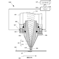
- FIG. 2 is a diagram for simply explaining the configuration and operation of the machining nozzle 200 according to the present embodiment.
- the processing nozzle 200 is a nozzle for performing processing by injecting the powder material 230 toward the molten pool 221 formed on the processing surface 220 by the laser beam 210 as an energy ray.
- the processing nozzle 200 includes a powder injection unit 201 and an adjustment unit 202.
- the powder injection unit 201 includes an inner casing 211 that forms a beam path through which the laser light 210 passes, and an outer casing 212 that is disposed via a gap 213 that serves as a flow path between the inner casing 211 and the powder material 230. And including.
- the inner casing 211 has a cylindrical shape and has a path through which the laser beam 210 passes, and emits the laser beam 210 from one end thereof.
- the outer surface of the inner casing 211 is narrowed toward the direction in which the laser light 210 is emitted.
- the outer casing 212 is also cylindrical and includes the inner casing 211, and the inner surface is narrowed in the emission direction of the laser light 210 emitted from the inner casing 211.
- the powder material 230 can be injected toward the molten pool 221.
- the gap 213 between the outer surface of the inner housing 211 and the inner surface of the outer housing 212 forms an injection port for the powder material 230, and the shape of the injection port is changed by the adjusting unit 202.
- the downstream ends of the inner casing 211 and the outer casing 212 are both represented as conical cylinder shapes, but the present invention is not limited to this. For example, both may have a polygonal pyramid shape. Further, the inner casing 211 may be cylindrical and only the downstream end of the outer casing 212 may be conical.
- the adjustment unit 202 adjusts the relative positions of the inner casing 211 and the outer casing 212.
- the adjustment unit 202 adjusts the relative horizontal position of the inner casing 211 and the outer casing 212 (a position on a plane perpendicular to the laser beam 210).
- only the outer casing 212 is horizontally moved (slided) in the direction opposite to the moving direction 222 to make a transition from the left state in FIG. 2 to the right state.
- the adjustment unit 202 adjusts the shape and / or position of the powder spot formed by the powder injection unit 201 according to the moving direction 222 of the molten pool 221 on the processing surface 220.
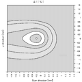
- FIG. 3 and 4 show the temperature distribution of the molten pool.
- the horizontal direction is the moving direction (scanning direction)
- the vertical direction is the Y direction (sub-scanning direction) orthogonal to the moving direction.
- the horizontal direction is the moving direction (scanning direction)
- the vertical direction is the direction (Z direction) orthogonal to the processing surface.
- the origin (0, 0) is the laser beam spot. From this temperature distribution, it can be seen that the molten pool spreads toward the downstream side in the moving direction. Therefore, it can be seen that the powder material should also be injected more downstream than the upstream side in the moving direction.
- the processing nozzle 200 includes, as the adjustment unit 202, an X direction driving unit 521, a Y direction driving unit 522, a driver 523 that drives these driving units, and a controller 524 that controls the driver 523. And a detection unit 525 that detects the shape of the molten pool 221.
- the detecting unit 525 is, for example, an imaging unit that images the processed surface 220 and detects the shape of the molten pool 221 from the captured image.
- the controller 524 instructs the driver 523 to move the outer casing 212 in accordance with the detected shape of the molten pool 221.
- the driver 523 transmits a drive command to the X direction drive unit 521 and the Y direction drive unit 522 in accordance with an instruction received from the controller 524. In this way, the horizontal position of the outer casing 212 with respect to the inner casing 211 is changed to adjust the shape and / or position of the powder spot.
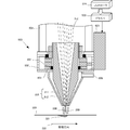
- FIG. 6 is a longitudinal sectional view showing the mechanical configuration of the machining nozzle 200.
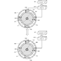
- FIG. 7 is a bottom view of the processing nozzle 200.
- the processing nozzle 200 is attached to a nozzle holder 602 fixed to the housing holder 601.
- the outer casing 212 is provided with a material supply unit 606.
- the inner casing 211 is fixed to the nozzle holder 602, and the outer casing 212 is movable in the horizontal direction with respect to the inner casing 211 on the XY stage 603.
- a drive motor 609 is provided as the adjustment unit 202.
- a seal 607 is attached to the upper end of the outer casing 212 so that the powder material does not leak from the gap with the inner casing 211 even when the outer casing 212 moves in the horizontal direction. ing.
- the machining nozzle 200 includes a drive motor 711 for the X-axis direction and a drive motor 712 for the Y-axis direction.
- the drive motors 711 and 712 change the flow of the powder material by moving the XY stage 603 and displacing the space (nozzle gap) between the inner casing 211 and the outer casing 212. That is, the outer casing 212 can be displaced in the XY directions based on the instruction value of the controller 524 following the changing scanning direction.
- a laser beam injection port 713 and a powder material injection port 714 appear at the bottom surface of the processing nozzle 200.
- the laser beam injection port 713 is a downstream end opening of the inner casing 211
- the powder material injection port 714 is an outer peripheral edge of the downstream end portion of the inner casing 211 and a downstream side of the outer casing 212. It is a gap with the inner periphery of the side end.
- the X-axis direction drive motor 711 and the Y-axis direction drive motor 712 change the horizontal position of the outer casing 212 relative to the inner casing 211, thereby changing the shape and position of the powder material injection port 714.
- the shape of the powder spot also changes. For example, as shown in FIG. 7, the state transitions between a state where the inner casing 211 and the outer casing 212 are arranged concentrically (upper figure) and a shifted state (lower figure).
- the injection region of the powder material can be changed in accordance with the molten pool without the need to replace the processing nozzle, and thus the processing accuracy and material can be changed.
- the utilization efficiency can be improved.
- FIG. 8 is a longitudinal sectional view for explaining the configuration of the machining nozzle 800 according to the present embodiment.
- FIG. 9 is a bottom view of the processing nozzle 800.
- the processing nozzle 800 according to the present embodiment has an outer casing 812 having a shape different from that of the outer casing 212 as compared to the second embodiment, and the inner casing 211 is moved in the horizontal direction by the drive motor 609. It is different in letting you. Since other configurations and operations are the same as those of the second embodiment, the same configurations and operations are denoted by the same reference numerals, and detailed description thereof is omitted.
- FIG. 10 is a longitudinal sectional view for explaining the configuration of the machining nozzle 1000 according to this embodiment.
- FIG. 11 is a bottom view of the processing nozzle 1000.
- the processing nozzle 1000 according to this embodiment differs from the second embodiment in that it has four piezoelectric elements 1001 to 1004 and a piezoelectric driver 1023 instead of the drive motors 711 and 712. Since other configurations and operations are the same as those of the second embodiment, the same configurations and operations are denoted by the same reference numerals, and detailed description thereof is omitted.
- the piezo elements 1001 to 1004 are used instead of the drive motor as the adjustment unit, the responsiveness of the change in the injection region of the powder material can be improved as compared with the second embodiment. .
- FIG. 12 is a longitudinal sectional view for explaining the configuration of the machining nozzle 1200 according to this embodiment.
- the processing nozzle 1200 according to the present embodiment is different from the fourth embodiment in that the inner casing 211 is moved using the piezo elements 1201 and 1202. Since other configurations and operations are the same as those in the fourth embodiment, the same configurations and operations are denoted by the same reference numerals, and detailed description thereof is omitted.
- the outer casing 812 is fixed and the inner casing 211 is moved using the piezo elements 1201 and 1202, the change in the injection region of the powder material compared to the second embodiment.
- the structure of the powder supply unit 606 can be simplified while improving the responsiveness.
- FIG. 13 is a longitudinal sectional view for explaining the configuration of the processing nozzle 1300 according to the present embodiment.
- the processing nozzle 1300 according to the present embodiment changes the relative angle formed by the axis of the inner casing 211 and the axis of the outer casing 212, thereby changing the shape of the powder injection port. Is different, and as a result, the shape of the powder spot is different. Since other configurations and operations are the same as those of the second embodiment, the same configurations and operations are denoted by the same reference numerals, and detailed description thereof is omitted.
- FIG. 13 is a diagram for simply explaining the configuration and operation of the machining nozzle 1300 according to the present embodiment.
- the processing nozzle 1300 is a nozzle for performing processing by injecting the powder material 230 toward the molten pool 221 formed on the processing surface 220 by the laser beam 210 as an energy ray.
- the processing nozzle 200 includes a powder injection unit 1301 and an adjustment unit 1302.
- the powder injection unit 1301 includes an inner casing 211 that constitutes a light beam path through which the laser light 210 passes, and an outer casing 1312 that is disposed via the inner casing 211 and the gap 213.
- the outer casing 1312 is also cylindrical and includes the inner casing 211, and the inner surface is narrowed in the emission direction of the laser light 210 emitted from the inner casing 211.
- the gap between the outer surface of the inner casing 211 and the inner surface of the outer casing 1312 forms an injection port for the powder material 230, and the shape of the injection port is changed by the adjusting unit 1302.
- the adjustment unit 1302 adjusts the relative positions of the inner casing 211 and the outer casing 1312.
- the adjustment unit 1302 adjusts the relative angle between the inner casing 211 and the outer casing 1312. In particular, by tilting only the outer casing 1312 in the opposite direction with respect to the moving direction 222, the state is shifted from the left side state in FIG. 2 to the right side state. Thereby, in the molten pool 221, the amount of the powder material 231 injected toward the downstream side in the movement direction from the laser beam 210 is larger than that of the powder material 232 injected toward the upstream side in the movement direction. That is, the adjustment unit 1302 adjusts the shape and / or position of the powder spot formed by the powder injection unit 1301 according to the moving direction 222 of the molten pool 221 on the processing surface 220.
- the processing nozzle 1300 includes, as the adjustment unit 1302, Z-direction drive units 1401 to 1404, a driver 1423 that drives these drive units, and a controller 1424 that controls the driver 1423.
- the angle of the outer casing 1312 with respect to the inner casing 211 is changed to adjust the shape and / or position of the powder spot.
- FIG. 15 is a longitudinal sectional view showing a mechanical configuration of the machining nozzle 1300.
- the inner casing 211 is fixed to the nozzle holder 602, and the outer casing 1312 can be displaced in the Z direction by the Z direction driving units 1401 to 1404 with respect to the inner casing 211. As a result, the inner casing 211 is displaced. Can be inclined with respect to Here, four piezoelectric elements are provided as an example of the Z-direction drive unit.
- a seal 607 is attached to the upper end of the outer casing 1312 so that the powder material does not leak from the gap with the inner casing 211 even when the outer casing 1312 is inclined.
- the shape and / or position of the powder spot formed by the powder injection unit 1301 is changed on the processing surface 220 by inclining the outer casing 1312 with respect to the inner casing 211. Adjustment was made according to the moving direction 222 of 221. Thereby, similarly to 2nd Embodiment, the injection area
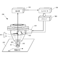
- the optical processing apparatus 1600 includes any one of the processing nozzles 100, 200, 800, 1000, 1200, and 1400 described in the above-described embodiment, and three-dimensionally melts the material with heat generated by the collected light. It is an apparatus that generates a modeled object (or overlay welding).
- an optical processing apparatus 1600 including the processing nozzle 200 will be described.
- the optical processing apparatus 1600 includes a light source 1601, an optical transmission unit 1615, a stage 1605, a material storage device 1606, a material supply unit 1630, a processing head 1608, and a control unit 1607.
- a laser light source is used as the light source 1601, but an LED, a halogen lamp, or a xenon lamp can be used.
- the energy beam used for melting the material is not limited to the laser beam, and any energy beam can be used as long as the powder material can be melted on the processed surface.
- an energy beam such as an electron beam or an electromagnetic wave in a microwave to ultraviolet region may be used.
- the light transmission unit 1615 is an optical fiber having a core diameter of ⁇ 0.01 to 1 mm, for example, and guides light generated by the light source 1601 to the processing head 1608.
- Stage 1605 is an X stage, an XY stage, or an XYZ stage. Each axis of XYX can be driven.
- the material container 1606 supplies a carrier gas containing a material to the processing head 1608 via the material supply unit 606.
- the material is particles such as metal particles and resin particles.
- the carrier gas is an inert gas, and may be, for example, argon gas, nitrogen gas, or helium gas.
- the material supply unit 606 is, for example, a resin or metal hose, and guides the powder flow in which the material is mixed into the carrier gas to the processing nozzle 200. However, when the material is a wire, no carrier gas is required.
- the machining head 1608 includes therein a focusing device that focuses light as energy rays, and a processing nozzle 200 is attached downstream of the focusing device.
- the laser beam supplied to the processing head 1608 is adjusted so as to be condensed on the processing surface 220 through an optical system including an internal lens or the like.
- the optical system is provided so as to be able to control the condensing position by controlling the lens interval and the like.
- the optical processing apparatus 1600 may include an attitude control mechanism and a position control mechanism for controlling the attitude and position of the machining head 1608. In this case, the attitude and position of the machining head 1608 are changed.
- the processing area on the processing surface is moved.
- the present invention is not limited to this, and the processing area on the processing surface may be moved by changing the posture and position of the stage 1605 while fixing the processing head 1608.
- the controller 524 inputs modeling conditions such as fine writing / bold writing and the shape of the modeled object, the output value of the laser light from the light source 1601, the position and orientation of the processing head 1608, the stage 1605 of the stage 1605 according to the input modeling conditions. While changing a position etc., the mechanical structure of the process nozzle 200 is changed, and a powder spot shape is changed. Thereby, the powder spot diameter by the powder material inject
- the modeled object 1610 is created on the stage 1605.
- Light emitted from the processing head 1608 is collected on the processing surface 220 on the modeled object 1610.
- the processing surface 220 is heated and condensed by light collection to form a molten pool in part.
- the material is injected from the processing nozzle 200 into the molten pool 221 on the processing surface 220. Then, the material melts into the molten pool 221. Thereafter, the molten pool 221 is cooled and solidified, whereby a material is deposited on the processed surface 220, and three-dimensional modeling is realized.
- the powder injection it is possible to adjust the powder injection by controlling the spot position and shape of the powder material in accordance with the shape of the molten pool. Therefore, the powder material can be efficiently supplied to the melting region.
- the present invention may be applied to a system composed of a plurality of devices, or may be applied to a single device. Furthermore, the present invention can also be applied to a case where an information processing program that implements the functions of the embodiments is supplied directly or remotely to a system or apparatus. Therefore, in order to realize the functions of the present invention on a computer, a program installed on the computer, a medium storing the program, and a WWW (World Wide Web) server that downloads the program are also included in the scope of the present invention. . In particular, at least a non-transitory computer readable medium storing a program for causing a computer to execute the processing steps included in the above-described embodiments is included in the scope of the present invention.
Landscapes
- Engineering & Computer Science (AREA)
- Physics & Mathematics (AREA)
- Chemical & Material Sciences (AREA)
- Optics & Photonics (AREA)
- Manufacturing & Machinery (AREA)
- Materials Engineering (AREA)
- Mechanical Engineering (AREA)
- Plasma & Fusion (AREA)
- Health & Medical Sciences (AREA)
- Analytical Chemistry (AREA)
- Automation & Control Theory (AREA)
- Electromagnetism (AREA)
- Toxicology (AREA)
- Oral & Maxillofacial Surgery (AREA)
- Thermal Sciences (AREA)
- Laser Beam Processing (AREA)
- Powder Metallurgy (AREA)
Abstract
Description
エネルギー線によって加工面上に形成された溶融プールに向けて粉体材料を射出させて加工を行なう際に、前記溶融プールの形状を検出する検出ステップと、
前記溶融プールに対して前記粉体材料を射出する粉体射出手段によって形成される粉体スポットの形状および/または位置を前記溶融プールの形状に合わせて調整する調整ステップと、
を含む。
エネルギー線によって加工面上に形成された溶融プールに向けて粉体材料を射出させて加工を行なう際に、前記溶融プールの形状を検出する検出ステップと、
前記溶融プールに対して前記粉体材料を射出する粉体射出手段によって形成される粉体スポットの形状および/または位置を前記溶融プールの形状に合わせて調整する調整ステップと、
をコンピュータに実行させる。
本発明の第1実施形態としての加工ノズル100について、図1を用いて説明する。図1は、本実施形態に係る加工ノズル100の概略構成図である。加工ノズル100は、エネルギー線110により加工面120上に形成された溶融プール121に向けて粉体材料130を射出させて加工を行なうためのノズルである。加工ノズル100は、粉体射出部101と、調整部102とを備える。
次に本発明の第2実施形態に係る加工ノズル200について、図2を用いて説明する。図2は、本実施形態に係る加工ノズル200の構成および動作を簡略的に説明するための図である。
次に本発明の第3実施形態に係る加工ノズル800について、図8、図9を用いて説明する。図8は、本実施形態に係る加工ノズル800の構成を説明するための縦断面図である。図9は、加工ノズル800の底面図である。本実施形態に係る加工ノズル800は、上記第2実施形態と比べると、外側筐体212とは異なる形状の外側筐体812を有し、駆動モータ609により、内側筐体211を水平方向に移動させる点で異なる。その他の構成および動作は、第2実施形態と同様であるため、同じ構成および動作については同じ符号を付してその詳しい説明を省略する。
[第4実施形態]
次に本発明の第4実施形態に係る加工ノズル1000について、図10、図11を用いて説明する。図10は、本実施形態に係る加工ノズル1000の構成を説明するための縦断面図である。図11は、加工ノズル1000の底面図である。本実施形態に係る加工ノズル1000は、上記第2実施形態と比べると、駆動モータ711、712の代わりに4つのピエゾ素子1001~1004とピエゾドライバ1023とを有する点で異なる。その他の構成および動作は、第2実施形態と同様であるため、同じ構成および動作については同じ符号を付してその詳しい説明を省略する。
次に本発明の第5実施形態に係る加工ノズル1200について、図12を用いて説明する。図12は、本実施形態に係る加工ノズル1200の構成を説明するための縦断面図である。本実施形態に係る加工ノズル1200は、上記第4実施形態と比べると、ピエゾ素子1201、1202を用いて内側筐体211を移動させる点で異なる。その他の構成および動作は、第4実施形態と同様であるため、同じ構成および動作については同じ符号を付してその詳しい説明を省略する。
次に本発明の第6実施形態に係る加工ノズル1300について、図13乃至図15を用いて説明する。図13は、本実施形態に係る加工ノズル1300の構成を説明するための縦断面図である。本実施形態に係る加工ノズル1300は、上記第2実施形態と比べると、内側筐体211の軸と外側筐体212の軸とが為す相対的な角度が変わることで、粉体射出口の形状が変わり、ひいては粉体スポットの形状が変わる点で異なる。その他の構成および動作は、第2実施形態と同様であるため、同じ構成および動作については同じ符号を付してその詳しい説明を省略する。
本発明の第7実施形態としての光加工装置(Optical Machining apparatus)について、図16を用いて説明する。光加工装置1600は、上述の実施形態で説明した加工ノズル100、200、800、1000、1200、1400のいずれかを含み、集光した光が生み出す熱で材料を溶融することにより三次元的な造形物(あるいは肉盛溶接)を生成する装置である。ここでは一例として、加工ノズル200を備えた光加工装置1600について説明する。
光加工装置1600は、光源1601、光伝送部1615、ステージ1605、材料収容装置1606、材料供給部1630、加工ヘッド1608および制御部1607を備えている。
次に、光加工装置1600の動作について説明する。造形物1610は、ステージ1605の上で作成される。加工ヘッド1608から射出される射出光は、造形物1610上の加工面220において集光される。加工面220は、集光によって昇温され、溶融され、一部に溶融プールを形成する。
以上、実施形態を参照して本願発明を説明したが、本願発明は上記実施形態に限定されるものではない。本願発明の構成や詳細には、本願発明のスコープ内で当業者が理解し得る様々な変更をすることができる。また、それぞれの実施形態に含まれる別々の特徴を如何様に組み合わせたシステムまたは装置も、本発明の範疇に含まれる。
Claims (9)
- エネルギー線によって加工面上に形成された溶融プールに対して粉体材料を射出する粉体射出手段と、
前記粉体射出手段によって形成される粉体スポットの形状および/または位置を前記溶融プールの形状に合わせて調整する調整手段と、
を備えた加工ノズル。 - 前記粉体射出手段は、
前記エネルギー線が通過するエネルギー線経路を構成する内側筐体と、
前記内側筐体と前記粉体材料の流路としての間隙を介して配置された外側筐体と、
を含み、
前記調整手段は、前記内側筐体と前記外側筐体の相対的な位置を調整する請求項1に記載の加工ノズル。 - 前記調整手段は、前記内側筐体と前記外側筐体の相対的な水平方向位置を調整する請求項2に記載の加工ノズル。
- 前記調整手段は、
前記粉体射出手段によって形成される粉体スポットの形状および/または位置を前記加工面上における前記溶融プールの移動方向に応じて調整する請求項1、2または3に記載の加工ノズル。 - 前記加工面を撮像して前記溶融プールの形状を検出する検出手段をさらに含む請求項1乃至4のいずれか1項に記載の加工ノズル。
- 請求項1乃至5のいずれ1項に記載の加工ノズルと、
前記エネルギー線を集束させる集束装置と、
を含むことを特徴とする加工ヘッド。 - 請求項6に記載の加工ヘッドと、
前記加工ヘッドに前記粉体材料を供給する材料供給部と、
前記加工ノズルを制御し、前記粉体材料のスポット径を制御する制御部と、
を備えた加工装置。 - エネルギー線によって加工面上に形成された溶融プールに向けて粉体材料を射出させて加工を行なう際に、前記溶融プールの形状を検出する検出ステップと、
前記溶融プールに対して前記粉体材料を射出する粉体射出手段によって形成される粉体スポットの形状および/または位置を前記溶融プールの形状に合わせて調整する調整ステップと、
を含む加工ノズルの制御方法。 - エネルギー線によって加工面上に形成された溶融プールに向けて粉体材料を射出させて加工を行なう際に、前記溶融プールの形状を検出する検出ステップと、
前記溶融プールに対して前記粉体材料を射出する粉体射出手段によって形成される粉体スポットの形状および/または位置を前記溶融プールの形状に合わせて調整する調整ステップと、
をコンピュータに実行させる加工ノズルの制御プログラム。
Priority Applications (4)
| Application Number | Priority Date | Filing Date | Title |
|---|---|---|---|
| PCT/JP2015/058627 WO2016151713A1 (ja) | 2015-03-20 | 2015-03-20 | 加工ノズル、加工ヘッド、加工装置、加工ノズルの制御方法および制御プログラム |
| JP2015549117A JP5997850B1 (ja) | 2015-03-20 | 2015-03-20 | 加工ノズル、加工ヘッド、加工装置、加工ノズルの制御方法および制御プログラム |
| US14/889,369 US20170087666A1 (en) | 2015-03-20 | 2015-03-20 | Processing nozzle, processing head, machining apparatus, and control method and control program of processing nozzle |
| EP15785038.9A EP3095592A4 (en) | 2015-03-20 | 2015-03-20 | Working nozzle, working head, working device, method for controlling working nozzle, and control program |
Applications Claiming Priority (1)
| Application Number | Priority Date | Filing Date | Title |
|---|---|---|---|
| PCT/JP2015/058627 WO2016151713A1 (ja) | 2015-03-20 | 2015-03-20 | 加工ノズル、加工ヘッド、加工装置、加工ノズルの制御方法および制御プログラム |
Publications (1)
| Publication Number | Publication Date |
|---|---|
| WO2016151713A1 true WO2016151713A1 (ja) | 2016-09-29 |
Family
ID=56977223
Family Applications (1)
| Application Number | Title | Priority Date | Filing Date |
|---|---|---|---|
| PCT/JP2015/058627 Ceased WO2016151713A1 (ja) | 2015-03-20 | 2015-03-20 | 加工ノズル、加工ヘッド、加工装置、加工ノズルの制御方法および制御プログラム |
Country Status (4)
| Country | Link |
|---|---|
| US (1) | US20170087666A1 (ja) |
| EP (1) | EP3095592A4 (ja) |
| JP (1) | JP5997850B1 (ja) |
| WO (1) | WO2016151713A1 (ja) |
Cited By (4)
| Publication number | Priority date | Publication date | Assignee | Title |
|---|---|---|---|---|
| JP2021024111A (ja) * | 2019-07-31 | 2021-02-22 | 技術研究組合次世代3D積層造形技術総合開発機構 | ノズル及び積層造形装置 |
| JP2022522186A (ja) * | 2019-02-27 | 2022-04-14 | オハイオ・ステイト・イノベーション・ファウンデーション | 運動量伝達法を用いた付加製造 |
| JP2022083439A (ja) * | 2020-11-24 | 2022-06-03 | コリア アトミック エナジー リサーチ インスティチュート | 金属コーティング方法、それにより形成されたコーティング層を含む金属部材及び燃料電池分離板 |
| DE112021005617T5 (de) | 2021-02-24 | 2023-08-24 | Mitsubishi Electric Corporation | Vorrichtung zur additiven Fertigung, System zur additiven Fertigung, Verfahren zur additiven Fertigung, Bearbeitungsprogrammerzeugungsprogramm und Lernvorrichtung |
Families Citing this family (14)
| Publication number | Priority date | Publication date | Assignee | Title |
|---|---|---|---|---|
| JP6801173B2 (ja) * | 2015-10-29 | 2020-12-16 | セイコーエプソン株式会社 | 三次元構造物の製造方法、その製造装置及びその制御プログラム |
| EP3332896A4 (en) * | 2016-10-05 | 2019-06-19 | Technology Research Association For Future Additiv | 3D PRINTING DEVICE, 3D PRINTING DEVICE CONTROL PROCEDURE, AND 3D PRINTING DEVICE CONTROL PROGRAM |
| CN107214958B (zh) * | 2017-07-27 | 2018-06-26 | 苏艳敏 | 一种双口径3d打印机喷头 |
| JP2019037997A (ja) * | 2017-08-23 | 2019-03-14 | 中村留精密工業株式会社 | レーザクラッディング装置 |
| CN107598163B (zh) * | 2017-09-01 | 2019-07-19 | 华中科技大学 | 一种适用于铺粉式增材制造的质量无损在线检测装备及方法 |
| JP6942014B2 (ja) | 2017-09-26 | 2021-09-29 | 技術研究組合次世代3D積層造形技術総合開発機構 | ノズル及び積層造形装置 |
| DE102018202203B4 (de) * | 2018-02-13 | 2022-06-23 | Fraunhofer-Gesellschaft zur Förderung der angewandten Forschung e.V. | Anordnung zur Justierung einer Pulverströmung in Bezug zur mittleren Längsachse eines Energiestrahls |
| JP7063670B2 (ja) * | 2018-03-26 | 2022-05-09 | 技術研究組合次世代3D積層造形技術総合開発機構 | ノズルおよび積層造形装置 |
| US11426818B2 (en) | 2018-08-10 | 2022-08-30 | The Research Foundation for the State University | Additive manufacturing processes and additively manufactured products |
| CN111251609A (zh) * | 2020-03-23 | 2020-06-09 | 麦递途医疗科技(上海)有限公司 | 一种打印头喷嘴组件及3d打印系统 |
| DE102021122972A1 (de) * | 2021-09-06 | 2023-03-09 | Rheinisch-Westfälische Technische Hochschule (RWTH) Aachen, Körperschaft des öffentlichen Rechts | Düsenvorrichtung und Verfahren zum Laserauftragsschweißen |
| DE102021133636B4 (de) | 2021-12-17 | 2024-03-07 | Fraunhofer-Gesellschaft zur Förderung der angewandten Forschung eingetragener Verein | Pulverzufuhrdüse, insbesondere für die Pulverzufuhr beim Laserauftragschweißen, und Verfahren zum Betrieb der Pulverzufuhrdüse |
| DE102021214891A1 (de) | 2021-12-22 | 2023-06-22 | HPL Technologies GmbH | Vorrichtung zum Beschichten von einem Werkstück |
| DE102024131460A1 (de) | 2024-10-29 | 2026-04-30 | TRUMPF Laser- und Systemtechnik SE | Vorrichtung und Verfahren zum Laserauftragschweißen |
Citations (6)
| Publication number | Priority date | Publication date | Assignee | Title |
|---|---|---|---|---|
| JPH10501463A (ja) * | 1994-01-27 | 1998-02-10 | クロマロイ ガス タービン コーポレイション | レーザーによる粉末金属クラッディングノズル |
| JPH11333584A (ja) * | 1998-05-26 | 1999-12-07 | Mitsubishi Heavy Ind Ltd | レーザ加工ヘッド |
| JP2002519200A (ja) * | 1998-06-30 | 2002-07-02 | ジオティー マズムダー | レーザクラッディング装置及び方法 |
| JP2006068819A (ja) * | 2004-08-31 | 2006-03-16 | Winkler & Duennebier Ag | 裁断ローラまたは型押しローラをレーザ肉盛溶接によって製作するための方法および装置 |
| JP2007222869A (ja) * | 2006-02-22 | 2007-09-06 | General Electric Co <Ge> | レーザネットシェイプ製造法のためのノズル |
| JP2011515099A (ja) | 2008-03-26 | 2011-05-19 | ダニスコ・ユーエス・インク | ジスルフィド結合含有タンパク質を生成するための宿主細胞及び方法 |
Family Cites Families (9)
| Publication number | Priority date | Publication date | Assignee | Title |
|---|---|---|---|---|
| DE9013943U1 (de) * | 1990-10-06 | 1991-01-03 | Trumpf GmbH & Co, 7257 Ditzingen | Laserdüse |
| JPH11285882A (ja) * | 1998-03-31 | 1999-10-19 | Amada Co Ltd | 制御機能付二重構造ノズル |
| EP1227910B1 (en) * | 1999-11-04 | 2007-07-25 | Aeromet Corporation | Control system for depositing powder to a molten puddle |
| US6995334B1 (en) * | 2003-08-25 | 2006-02-07 | Southern Methodist University | System and method for controlling the size of the molten pool in laser-based additive manufacturing |
| DE102008057309B3 (de) * | 2008-11-13 | 2009-12-03 | Trumpf Laser- Und Systemtechnik Gmbh | Verfahren und Laserbearbeitungsmaschine zum Ermitteln einer Dejustage einer Pulverzufuhrdüse der Laserbearbeitungsmaschine |
| JP5292256B2 (ja) * | 2009-10-20 | 2013-09-18 | 株式会社日立製作所 | レーザ加工ヘッド、及びレーザ肉盛方法 |
| JP5616769B2 (ja) * | 2010-12-13 | 2014-10-29 | 株式会社日立製作所 | レーザ加工ヘッド及び肉盛溶接方法 |
| WO2015146591A1 (ja) * | 2014-03-27 | 2015-10-01 | プライムアースEvエナジー 株式会社 | レーザ溶接装置、レーザ溶接方法及び電池ケース |
| WO2016139775A1 (ja) * | 2015-03-04 | 2016-09-09 | 技術研究組合次世代3D積層造形技術総合開発機構 | 加工ノズル、加工ヘッド、加工装置、その制御方法および制御プログラム |
-
2015
- 2015-03-20 WO PCT/JP2015/058627 patent/WO2016151713A1/ja not_active Ceased
- 2015-03-20 EP EP15785038.9A patent/EP3095592A4/en not_active Withdrawn
- 2015-03-20 JP JP2015549117A patent/JP5997850B1/ja active Active
- 2015-03-20 US US14/889,369 patent/US20170087666A1/en not_active Abandoned
Patent Citations (6)
| Publication number | Priority date | Publication date | Assignee | Title |
|---|---|---|---|---|
| JPH10501463A (ja) * | 1994-01-27 | 1998-02-10 | クロマロイ ガス タービン コーポレイション | レーザーによる粉末金属クラッディングノズル |
| JPH11333584A (ja) * | 1998-05-26 | 1999-12-07 | Mitsubishi Heavy Ind Ltd | レーザ加工ヘッド |
| JP2002519200A (ja) * | 1998-06-30 | 2002-07-02 | ジオティー マズムダー | レーザクラッディング装置及び方法 |
| JP2006068819A (ja) * | 2004-08-31 | 2006-03-16 | Winkler & Duennebier Ag | 裁断ローラまたは型押しローラをレーザ肉盛溶接によって製作するための方法および装置 |
| JP2007222869A (ja) * | 2006-02-22 | 2007-09-06 | General Electric Co <Ge> | レーザネットシェイプ製造法のためのノズル |
| JP2011515099A (ja) | 2008-03-26 | 2011-05-19 | ダニスコ・ユーエス・インク | ジスルフィド結合含有タンパク質を生成するための宿主細胞及び方法 |
Non-Patent Citations (1)
| Title |
|---|
| See also references of EP3095592A4 |
Cited By (8)
| Publication number | Priority date | Publication date | Assignee | Title |
|---|---|---|---|---|
| JP2022522186A (ja) * | 2019-02-27 | 2022-04-14 | オハイオ・ステイト・イノベーション・ファウンデーション | 運動量伝達法を用いた付加製造 |
| US12157168B2 (en) | 2019-02-27 | 2024-12-03 | Ohio State Innovation Foundation | Additive manufacturing using a momentum transfer method |
| JP2021024111A (ja) * | 2019-07-31 | 2021-02-22 | 技術研究組合次世代3D積層造形技術総合開発機構 | ノズル及び積層造形装置 |
| JP7184713B2 (ja) | 2019-07-31 | 2022-12-06 | 技術研究組合次世代3D積層造形技術総合開発機構 | ノズル及び積層造形装置 |
| JP2022083439A (ja) * | 2020-11-24 | 2022-06-03 | コリア アトミック エナジー リサーチ インスティチュート | 金属コーティング方法、それにより形成されたコーティング層を含む金属部材及び燃料電池分離板 |
| JP7373540B2 (ja) | 2020-11-24 | 2023-11-02 | コリア アトミック エナジー リサーチ インスティチュート | 金属コーティング方法、それにより形成されたコーティング層を含む金属部材及び燃料電池分離板 |
| DE112021005617T5 (de) | 2021-02-24 | 2023-08-24 | Mitsubishi Electric Corporation | Vorrichtung zur additiven Fertigung, System zur additiven Fertigung, Verfahren zur additiven Fertigung, Bearbeitungsprogrammerzeugungsprogramm und Lernvorrichtung |
| US12011779B2 (en) | 2021-02-24 | 2024-06-18 | Mitsubishi Electric Corporation | Additive manufacturing apparatus, additive manufacturing system, additive manufacturing method, storage medium, and learning device |
Also Published As
| Publication number | Publication date |
|---|---|
| US20170087666A1 (en) | 2017-03-30 |
| EP3095592A4 (en) | 2017-11-01 |
| EP3095592A1 (en) | 2016-11-23 |
| JP5997850B1 (ja) | 2016-09-28 |
| JPWO2016151713A1 (ja) | 2017-04-27 |
Similar Documents
| Publication | Publication Date | Title |
|---|---|---|
| JP5997850B1 (ja) | 加工ノズル、加工ヘッド、加工装置、加工ノズルの制御方法および制御プログラム | |
| JP6289565B2 (ja) | 加工ノズル、加工ヘッド、加工装置、加工方法および加工プログラム | |
| JP6234551B2 (ja) | 加工ノズル、加工ヘッド、加工装置、その制御方法および制御プログラム | |
| EP3862128B1 (en) | Method of controlling the cooling rate of a melt pool of a powder bed, and direct metal laser melting manufacturing system with in-line laser scanner | |
| TWI726855B (zh) | 造形裝置及造形方法 | |
| CN109789512B (zh) | 用于将第一和第二工件区段激光焊接的方法和激光加工机 | |
| JP6505022B2 (ja) | 部品製造装置および方法 | |
| JP5806113B2 (ja) | ファイバレーザを備えたレーザ溶接工具 | |
| JP6560678B2 (ja) | レーザー光線、レーザー工具、レーザー機械、機械コントローラを用いた工作物の機械加工方法 | |
| CN110709195B (zh) | 造型系统及造型方法 | |
| US20180318926A1 (en) | Additive manufacturing apparatus | |
| CN109475980A (zh) | 激光焊接、包覆和/或增材制造系统以及激光焊接、包覆和/或增材制造的方法 | |
| CN109570779A (zh) | 一种激光加工方法及激光加工系统 | |
| JP2011529401A5 (ja) | ||
| JP6134861B2 (ja) | 光加工ヘッド、光加工装置および光加工方法 | |
| KR100661427B1 (ko) | 레이저 용접 시스템 및 레이저 용접의 제어 방법 | |
| JP7382554B2 (ja) | レーザ加工装置及びそれを用いたレーザ加工方法 | |
| JP2018521217A (ja) | 少なくとも一つの三次元物体を付加的に製造する装置 | |
| CN108081602B (zh) | 用于添加式地制造三维物体的方法 | |
| JP5495574B2 (ja) | レーザはんだ付け方法 | |
| CN104228342A (zh) | 基于喷墨打印和选择性激光熔化的布线系统及方法 | |
| JP2010207878A (ja) | レーザ溶接装置 | |
| EP3978182B1 (en) | Laser machining device and laser machining method using same | |
| CN108136541A (zh) | 具有用于直接金属沉积的激光扫描头的喷嘴 | |
| JP7512851B2 (ja) | 積層造形装置、および、線状部材の製造方法 |
Legal Events
| Date | Code | Title | Description |
|---|---|---|---|
| ENP | Entry into the national phase |
Ref document number: 2015549117 Country of ref document: JP Kind code of ref document: A |
|
| REEP | Request for entry into the european phase |
Ref document number: 2015785038 Country of ref document: EP |
|
| WWE | Wipo information: entry into national phase |
Ref document number: 14889369 Country of ref document: US Ref document number: 2015785038 Country of ref document: EP |
|
| 121 | Ep: the epo has been informed by wipo that ep was designated in this application |
Ref document number: 15785038 Country of ref document: EP Kind code of ref document: A1 |
|
| NENP | Non-entry into the national phase |
Ref country code: DE |