WO2016151746A1 - 樹脂製容器の蓋構造 - Google Patents
樹脂製容器の蓋構造 Download PDFInfo
- Publication number
- WO2016151746A1 WO2016151746A1 PCT/JP2015/058840 JP2015058840W WO2016151746A1 WO 2016151746 A1 WO2016151746 A1 WO 2016151746A1 JP 2015058840 W JP2015058840 W JP 2015058840W WO 2016151746 A1 WO2016151746 A1 WO 2016151746A1
- Authority
- WO
- WIPO (PCT)
- Prior art keywords
- cap
- screw portion
- mouth
- lid structure
- peripheral surface
- Prior art date
- Legal status (The legal status is an assumption and is not a legal conclusion. Google has not performed a legal analysis and makes no representation as to the accuracy of the status listed.)
- Ceased
Links
Images




Classifications
-
- B—PERFORMING OPERATIONS; TRANSPORTING
- B65—CONVEYING; PACKING; STORING; HANDLING THIN OR FILAMENTARY MATERIAL
- B65D—CONTAINERS FOR STORAGE OR TRANSPORT OF ARTICLES OR MATERIALS, e.g. BAGS, BARRELS, BOTTLES, BOXES, CANS, CARTONS, CRATES, DRUMS, JARS, TANKS, HOPPERS, FORWARDING CONTAINERS; ACCESSORIES, CLOSURES, OR FITTINGS THEREFOR; PACKAGING ELEMENTS; PACKAGES
- B65D41/00—Caps, e.g. crown caps or crown seals, i.e. members having parts arranged for engagement with the external periphery of a neck or wall defining a pouring opening or discharge aperture; Protective cap-like covers for closure members, e.g. decorative covers of metal foil or paper
- B65D41/02—Caps or cap-like covers without lines of weakness, tearing strips, tags, or like opening or removal devices
- B65D41/04—Threaded or like caps or cap-like covers secured by rotation
- B65D41/0407—Threaded or like caps or cap-like covers secured by rotation with integral sealing means
- B65D41/0414—Threaded or like caps or cap-like covers secured by rotation with integral sealing means formed by a plug, collar, flange, rib or the like contacting the internal surface of a container neck
- B65D41/0421—Threaded or like caps or cap-like covers secured by rotation with integral sealing means formed by a plug, collar, flange, rib or the like contacting the internal surface of a container neck and combined with integral sealing means contacting other surfaces of a container neck
-
- B—PERFORMING OPERATIONS; TRANSPORTING
- B65—CONVEYING; PACKING; STORING; HANDLING THIN OR FILAMENTARY MATERIAL
- B65D—CONTAINERS FOR STORAGE OR TRANSPORT OF ARTICLES OR MATERIALS, e.g. BAGS, BARRELS, BOTTLES, BOXES, CANS, CARTONS, CRATES, DRUMS, JARS, TANKS, HOPPERS, FORWARDING CONTAINERS; ACCESSORIES, CLOSURES, OR FITTINGS THEREFOR; PACKAGING ELEMENTS; PACKAGES
- B65D41/00—Caps, e.g. crown caps or crown seals, i.e. members having parts arranged for engagement with the external periphery of a neck or wall defining a pouring opening or discharge aperture; Protective cap-like covers for closure members, e.g. decorative covers of metal foil or paper
- B65D41/02—Caps or cap-like covers without lines of weakness, tearing strips, tags, or like opening or removal devices
- B65D41/04—Threaded or like caps or cap-like covers secured by rotation
-
- B—PERFORMING OPERATIONS; TRANSPORTING
- B65—CONVEYING; PACKING; STORING; HANDLING THIN OR FILAMENTARY MATERIAL
- B65D—CONTAINERS FOR STORAGE OR TRANSPORT OF ARTICLES OR MATERIALS, e.g. BAGS, BARRELS, BOTTLES, BOXES, CANS, CARTONS, CRATES, DRUMS, JARS, TANKS, HOPPERS, FORWARDING CONTAINERS; ACCESSORIES, CLOSURES, OR FITTINGS THEREFOR; PACKAGING ELEMENTS; PACKAGES
- B65D41/00—Caps, e.g. crown caps or crown seals, i.e. members having parts arranged for engagement with the external periphery of a neck or wall defining a pouring opening or discharge aperture; Protective cap-like covers for closure members, e.g. decorative covers of metal foil or paper
- B65D41/02—Caps or cap-like covers without lines of weakness, tearing strips, tags, or like opening or removal devices
- B65D41/04—Threaded or like caps or cap-like covers secured by rotation
- B65D41/0471—Threaded or like caps or cap-like covers secured by rotation with means for positioning the cap on the container, or for limiting the movement of the cap, or for preventing accidental loosening of the cap
-
- B—PERFORMING OPERATIONS; TRANSPORTING
- B65—CONVEYING; PACKING; STORING; HANDLING THIN OR FILAMENTARY MATERIAL
- B65D—CONTAINERS FOR STORAGE OR TRANSPORT OF ARTICLES OR MATERIALS, e.g. BAGS, BARRELS, BOTTLES, BOXES, CANS, CARTONS, CRATES, DRUMS, JARS, TANKS, HOPPERS, FORWARDING CONTAINERS; ACCESSORIES, CLOSURES, OR FITTINGS THEREFOR; PACKAGING ELEMENTS; PACKAGES
- B65D51/00—Closures not otherwise provided for
- B65D51/16—Closures not otherwise provided for with means for venting air or gas
- B65D51/1633—Closures not otherwise provided for with means for venting air or gas whereby venting occurs by automatic opening of the closure, container or other element
- B65D51/1661—Closures not otherwise provided for with means for venting air or gas whereby venting occurs by automatic opening of the closure, container or other element by means of a passage for the escape of gas between the closure and the lip of the container mouth
Definitions
- the present invention relates to a lid structure for a resin container, and more specifically, a cap having a mouth portion having a male screw portion on the outer peripheral surface and a female screw portion having a plurality of protrusions intermittently connected in the circumferential direction on the inner peripheral surface.
- the male screw part has at least a part of the circumferential direction having one screw part in which the number of threads between the front end and the end of the mouth part is one, and the mouth part
- the present invention relates to a lid structure for a resin container in which the female screw portion of the cap is screwed into a male screw portion, and the mouth portion is wound and sealed with the cap.
- the inventor when the male screw portion has one screw portion where the number of threads between the front end and the end of the mouth portion is one in a part in the circumferential direction, It has been found that the force to prevent the female screw portion from being pushed up in the portion is weakened. In this case, when the internal pressure in the resin container increases, the sealed state in the resin container is hindered, and carbonic acid may escape. In order to solve this problem, it is conceivable to change the design of the mouth so that one screw portion does not occur, but this also involves a change in the design of the cap. In addition, there are also inconveniences such as increasing the height of the mouth by increasing the screw thread, becoming a special specification and making the mouth standard unusable.
- an object of the present invention is to provide a lid structure for a resin container that suitably keeps the sealed state in the resin container simply by changing the configuration of the cap.
- the lid structure of the resin container according to the present invention is A mouth portion having a male screw portion on the outer peripheral surface; A cap having a female screw portion on the inner peripheral surface, the plurality of protrusions being intermittently continuous in the circumferential direction,
- the male screw portion has one screw portion in which at least a part of the circumferential direction has one screw thread between the distal end and the end of the mouth portion,
- a resin container lid structure in which the female screw portion of the cap is screwed into the male screw portion of the mouth portion, and the mouth portion is wound and sealed by the cap,
- the projecting portion of the female screw portion mounted on the lower side of the one screw portion in the male screw portion, and an extended projection having a circumferential length longer than the circumferential length of the other projecting portion Is provided.
- a gap is formed in the female threaded part of the cap in order to reduce the weight and to remove the residue remaining in the female threaded part when the cap is attached, and to efficiently release the internal pressure.
- the plurality of protrusions are intermittently connected in the circumferential direction.
- the inventor is engaged with one screw portion in the shape of the female screw portion of the cap in which a plurality of protrusions are intermittently connected, without changing the shape of the male screw portion of the mouth portion, for the above problem. It has been found that the protrusions (that are arranged on the lower side of one screw part) can be reinforced by increasing the length thereof to prevent the female screw part from being pushed up. In other words, the push-up of the female screw part is accompanied by the deformation of the protrusion part, but the deformation of the protrusion part can be suppressed by increasing the length of the protrusion part. Pushing up is suppressed.
- the protrusion disposed below the one screw portion is an extended protrusion having a circumferential length longer than the circumferential length of the other protrusion. Raising can be suppressed, and pushing up of the top surface of the cap can be suppressed. Therefore, the sealed state in the resin container can be suitably maintained only by changing the configuration of the cap.
- the extended protrusion is wound around the cap by a minimum amount necessary for sealing the mouth from a maximum winding state where the cap is tightly wound around the mouth. It is preferable that it is provided in a range arranged below the one screw portion over the tightened minimum winding state.
- the mouth in order to seal the mouth with the cap, it is not always necessary to wrap the cap to the mouth to the maximum extent (maximum tightening state).
- maximum tightening state When tightened (minimum winding state), the mouth can be sealed. That is, the mouth portion can be in a hermetically sealed state as long as the tightening amount is between the maximum winding state and the minimum winding state.
- the extending projection part is provided in the range by which the extending projection part is arrange
- the maximum winding state In any amount of tightening between the minimum tightening state, the extended protrusion is positioned below one screw portion, and the push-up of the female screw portion can be suppressed with higher accuracy.
- the protruding height of the extending protrusion from the inner peripheral surface of the cap is higher than the protruding height of the other protrusions.
- the female screw portion can be further prevented from being pushed up, and the top surface of the cap can be further restrained from being pushed up. .
- the end edge of the extending protrusion is angular.
- the extended protrusion is strongly caught by one screw portion. Therefore, the push-up of the female screw part can be further suppressed, and the push-up of the top surface of the cap can be further suppressed.
- a rib that connects between an outer seal portion that seals an outer peripheral surface of the mouth portion of the cap and an inner peripheral surface of the cap is provided at least in a portion corresponding to the one screw portion. Is preferred.
- the top surface of the cap is pushed up because the top surface portion of the cap expands and deforms.
- the rib since the rib is provided between the outer seal portion and the inner peripheral surface of the cap, the rib can suppress the top surface portion of the cap from expanding and deforming at a portion corresponding to the one screw portion. be able to. Therefore, it is possible to further suppress the top surface of the cap from being pushed up.
- lid structure Cap cross section front view Description perspective view of the lid structure in the maximum winding state Description perspective view of the lid structure in the minimum winding state (A) Cross-sectional view showing a state in which the extended protrusion is positioned below one screw portion, (b) Cross-sectional view showing a state in which another protrusion is positioned below the one screw portion Cross section of cap
- the lid structure S of the resin container according to the present embodiment includes a mouth portion 10 having a male screw portion 12 on the outer peripheral surface 11 and a female screw portion 22 in which a plurality of protrusions 23 are intermittently connected in the circumferential direction.
- a male screw part 12 having at least a part in the circumferential direction and a single screw part 13a having one screw thread between the tip and the end of the mouth part 10.
- the female screw portion 22 of the cap 20 is screwed into the male screw portion 12 of the mouth portion 10, and the mouth portion 10 is wound and sealed with the cap 20.
- the protruding portion 23 of the female screw portion 22 disposed below the one screw portion 13a of the male screw portion 12 is extended so that the circumferential length is longer than the circumferential length of the other protruding portion 23.
- Protrusions 24 and 25 are provided. Thereby, the force which prevents the female screw part 22 from being pushed up can be reinforced, and the top face 26 of the cap 20 can be prevented from being pushed up.
- a plastic bottle 1 hereinafter referred to as a resin container
- the lid structure S includes a mouth portion 10 of the bottle 1 and a cap 20 attached to the mouth portion 10.
- the mouth portion 10 has a male screw portion 12 on the outer peripheral surface 11, and the cap 20 has a female screw portion 22 on the inner peripheral surface 21.
- the female screw portion 22 of the cap 20 is screwed into the male screw portion 12 of the mouth portion 10, and the mouth portion 10 is wound and sealed with the cap 20.
- the bottle 1 can be integrally molded by a stretch molding method such as biaxial stretch blow molding using a thermoplastic resin such as polyethylene, polypropylene, or polyethylene terephthalate as a main material.
- the capacity of the bottle 1 is not particularly limited, and can be about 200 ml to 2 liters which are generally distributed.
- the liquid with which the bottle 1 is filled is not particularly limited.
- beverages such as drinking water, tea, fruit juice, coffee, cocoa, soft drinks, alcoholic beverages, milk beverages, soups, and liquid seasonings such as sauces and soy sauces. Fees.
- the lid structure S in this embodiment is stored in a place where the atmospheric temperature is high, the internal pressure in the bottle 1 is particularly increased due to the occurrence of carbonic acid loss from the liquid in addition to the thermal expansion of the contents. This is particularly preferable when the bottle 1 is filled with a carbonated beverage.
- the lid structure S in the present embodiment can also be suitably used for a non-carbonated beverage.
- the male screw portion 12 in the mouth portion 10 is formed by intermittently connecting a screw thread 13 protruding in a radial direction (a direction perpendicular to the outer peripheral surface 11) from the outer peripheral surface 11 in a spiral shape in the circumferential direction.
- the male screw part 12 has the one screw part 13a in which the number of the screw threads 13 in the middle is one from the front-end
- the female screw portion 22 in the cap 20 includes a plurality of protrusions 23 intermittently connected in the circumferential direction. Then, the male screw portion 12 (screw thread 13) and the female screw portion 22 (projection) so that the screw thread 13 of the male screw portion 12 is accommodated in a gap formed between the two protrusion portions 23 arranged in the vertical direction. Part 23) is formed in a complementary manner.
- two extending projections 24 and 25 having a circumferential length longer than the circumferential length of the other projections 23 among the projections 23 are continuously provided.
- the extended protrusions 24 and 25 are located below the one screw portion 13a of the male screw portion 12 (the end side of the mouth portion 10) when the mouth portion 10 is wound and sealed with the cap 20.
- the mouth portion 10 can be sealed. In other words, the mouth portion 10 can be in a sealed state as long as the amount of winding is between the maximum winding state and the minimum winding state.
- the difference in the amount of tightening between the maximum winding state and the minimum winding state is a central angle of 35 ° when the outer peripheral surface 11 of the mouth portion 10 is a circumference. Corresponds to the length of the arc.
- the length of each of the extending protrusions 24 and 25 is a length corresponding to the length of an arc having a central angle of 35 ° when the outer peripheral surface 11 of the mouth 10 is a circumference. That is, the extended protrusions 24 and 25 are provided in a range of an arc having a central angle of 70 °.
- the extended protrusion 24 is arranged below the one screw portion 13a.
- the extended protrusion 25 is one. It arrange
- both extending protrusions 24 and 25 are disposed below one screw portion 13a. That is, the extended protrusions 24 and 25 are provided in a range in which the extended protrusion 24 and / or the extended protrusion 25 are arranged below the one screw portion 13a from the maximum winding state to the minimum winding state. It is in the state that was.
- FIG. 5A shows a state in which the extended protrusion 24 is positioned below the one screw portion 13a
- FIG. 5B shows another protrusion 23 positioned below the one screw portion 13a. Indicates the state.
- the protrusion height from the inner peripheral surface 21 of the cap 20 is higher than the protrusion height of the other protrusions 23.
- the extended protrusion 24 has a tip edge 24a that is angular.
- the protruding height from the inner peripheral surface 21 of the cap 20 is set higher than the protruding height of the other protruding portions 23, and the leading edge thereof. Is angry.
- an outer seal portion 27 that seals the outer peripheral surface 11 of the mouth portion 10 is formed on the inner side surface 26 a of the top surface 26 of the cap 20 so as to protrude.
- a rib 28 connecting the outer seal portion 27 and the inner peripheral surface 21 of the cap 20 is provided in a portion corresponding to the one screw portion 13a when the mouth portion 10 is tightly sealed by the cap 20 and sealed. is there. More specifically, ribs 28 are provided above the extended protrusions 24 and 25, respectively.
- the extended protrusion 24 and / or the extended protrusion 25 is disposed below the one screw portion 13 a. That is, when the internal pressure in the bottle 1 increases and the top surface 26 of the cap 20 is pushed up, the one screw portion 13a engages with the extended protrusion 24 and / or the extended protrusion 25. Become.
- the force to prevent the female screw portion 12 to be engaged from being pushed up is usually weak.
- the extending protrusions 24 and 25 to be engaged are in the circumferential direction. The length is long and the deformation can be suppressed, and the one screw portion 13a suppresses the female screw portion 12 from being pushed up.
- the protrusion height from the inner peripheral surface 21 of the cap 20 is higher than the protrusion height of the other protrusions 23.
- the area where the extended protrusion 24 abuts against the one screw portion 13a is increased.
- the extended protrusion 24 has a square end edge 24a, and the extended protrusion 24 is strongly hooked by the one screw portion 13a.
- the push-up of the female screw portion 13 is further suppressed.
- the extended protrusion 25 has the same shape as the extended protrusion 24 and has the same effect.
- the rib 28 which connects between the outer seal part 27 and the internal peripheral surface 21 of the cap 20 is provided in the part corresponding to the one screw part 13a, it suppresses that the top
- the force that prevents the female screw portion 23 from being pushed up in the one screw portion 13a is reinforced, and the top surface 26 of the cap 20 is prevented from expanding and deforming.
- the push-up of the top surface 26 of the cap 20 can be suppressed.
- the hermetic state in the bottle 1 can be suitably maintained only by changing the configuration of the cap 20.
- the configuration in which the two extending protrusions 24 and 25 are continuously provided has been described as an example.
- the embodiment of the present invention is not limited to this.
- a configuration in which one extended protrusion having a length obtained by combining the two extended protrusions 24 and 25 may be provided.
- what is necessary is just to change suitably the length dimension of the extension protrusion parts 24 and 25 according to the length of the circumferential direction of the one screw part in resin-made containers.
- the extended protrusions 24 and 25 extend from the maximum winding state to the minimum winding state, and the extension protrusion 24 and / or the extension protrusion 25 is below the one screw portion 13a.
- the embodiment of the present invention is not limited to this.
- the extension protrusions 24 and 25 are provided with the single screw portion 13a only when the maximum winding state is only, the minimum winding state is only, or only when the amount of tightening is between the maximum winding state and the minimum winding state. It is good also as a structure arrange
- the protruding height from the inner peripheral surface 21 of the cap 20 in the extended protruding portion 24 is higher than the protruding height of the other protruding portions 23.
- the configuration in which the leading edge 24a is squared has been described as an example.
- the embodiment of the present invention is not limited to this.
- the protruding height from the inner peripheral surface 21 may be the same as that of the other protrusions 23, and the tip edge 24a may be configured with a corner cut off. Similar changes can be made to the extended protrusions 25.
- the configuration in which the rib 28 that connects the outer seal portion 27 and the inner peripheral surface 21 of the cap 20 is provided in the portion corresponding to the one screw portion 13a has been described as an example.
- the embodiment of the present invention is not limited to this.
- the configuration may be such that the rib 28 is not provided, or the configuration in which the rib 28 is provided in addition to the portion corresponding to the one screw portion 13a.
- the present invention can be used, for example, for a lid structure of a resin container in which a liquid is filled.
Landscapes
- Engineering & Computer Science (AREA)
- Mechanical Engineering (AREA)
- Closures For Containers (AREA)
Abstract
キャップの構成を変更するのみで樹脂製容器内の密閉状態を好適に保つ。樹脂製容器(1)の蓋構造(S)は、雄ネジ部(12)を外周面(11)に有する口部(10)と、複数の突起部(23)が周方向に断続的に連なってなる雌ネジ部(22)を内周面(21)に有するキャップ(20)とを有し、雄ネジ部(12)が、口部(10)の周方向の一部において、口部(10)の先端から末端の間におけるネジ山数が一本である一ネジ部分を有し、口部(10)の雄ネジ部(12)にキャップ(20)の雌ネジ部(22)を螺合させて口部(10)をキャップ(20)により巻き締めて密閉する。そして、蓋構造(S)では、雄ネジ部(12)における一ネジ部分(13a)の下側に配置される雌ネジ部(22)における突起部(24,25)であって、他の突起部(23)の周方向の長さより周方向の長さが長い延設突起部(24,25)を設けてある。
Description
本発明は、樹脂製容器の蓋構造、詳しくは、雄ネジ部を外周面に有する口部と、複数の突起部が周方向に断続的に連なってなる雌ネジ部を内周面に有するキャップと、を有し、前記雄ネジ部は、少なくとも周方向の一部において、前記口部の先端から末端の間におけるネジ山数が一本である一ネジ部分を有し、前記口部の前記雄ネジ部に前記キャップの前記雌ネジ部を螺合させて前記口部を前記キャップにより巻き締めて密閉する樹脂製容器の蓋構造に関する。
例えば、炭酸飲料を樹脂製容器に充填した場合、炭酸飲料は雰囲気温度が高い場所で保管されると、内容物が熱膨張し、さらに、液中から炭酸が抜けていき、これに伴い樹脂製容器内の内圧が高まる。内圧が高まるとキャップの天面が押し上げられる状態となるが、口部に設けた雄ネジ部とキャップの雌ネジ部とが螺合状態にあるため、雄ネジ部がその下側の雌ネジ部の押上げを防ぎ、これにより、キャップの天面の押し上げが抑制される。この結果、樹脂製容器内は密閉状態に保たれ、炭酸の抜けが抑制される。
これに対し、発明者は、雄ネジ部が、周方向の一部において、口部の先端から末端の間におけるネジ山数が一本となる一ネジ部分を有している場合、その一ネジ部分において雌ネジ部の押上げを防ぐ力が弱くなることを見出した。この場合、樹脂製容器内の内圧が高まったときに、樹脂製容器内の密閉状態が妨げられ、炭酸が抜けてしまう虞がある。これを解決するため、一ネジ部分が生じないように口部を設計変更することが考えられるが、これはキャップの設計変更も伴わせることになる。また、ネジ山を増やすことで口部高さが増加する、特殊仕様になり口部規格が汎用でなくなる、などの不都合もある。
そこで、本発明の目的は、キャップの構成を変更するのみで樹脂製容器内の密閉状態を好適に保つ樹脂製容器の蓋構造を提供することにある。
本発明に係る樹脂製容器の蓋構造は、
雄ネジ部を外周面に有する口部と、
複数の突起部が周方向に断続的に連なってなる雌ネジ部を内周面に有するキャップと、を有し、
前記雄ネジ部は、少なくとも周方向の一部において、前記口部の先端から末端の間におけるネジ山数が一本である一ネジ部分を有し、
前記口部の前記雄ネジ部に前記キャップの前記雌ネジ部を螺合させて前記口部を前記キャップにより巻き締めて密閉する樹脂製容器の蓋構造であって、
前記雄ネジ部における前記一ネジ部分の下側に載置される前記雌ネジ部における前記突起部であって、他の前記突起部の周方向の長さより周方向の長さが長い延設突起部を設けてある。
雄ネジ部を外周面に有する口部と、
複数の突起部が周方向に断続的に連なってなる雌ネジ部を内周面に有するキャップと、を有し、
前記雄ネジ部は、少なくとも周方向の一部において、前記口部の先端から末端の間におけるネジ山数が一本である一ネジ部分を有し、
前記口部の前記雄ネジ部に前記キャップの前記雌ネジ部を螺合させて前記口部を前記キャップにより巻き締めて密閉する樹脂製容器の蓋構造であって、
前記雄ネジ部における前記一ネジ部分の下側に載置される前記雌ネジ部における前記突起部であって、他の前記突起部の周方向の長さより周方向の長さが長い延設突起部を設けてある。
通常、軽量化の要請と、キャップ装着時にこぼれて雌ネジ部に残留した残留物を取り除けるようにするため、及び、内部の圧力を効率よく逃がすために、キャップの雌ネジ部には隙間を形成し、複数の突起部が周方向に断続的に連なるようにしてある。そして、発明者は、上記課題に対して、口部の雄ネジ部の形状を変更することなく、複数の突起部が断続的に連なるキャップの雌ネジ部の形状において、一ネジ部分と係合する(即ち一ネジ部分の下側に配置される)突起部について、その長さを長くすることで雌ネジ部の押上げを防ぐ力を補強できることを見出した。つまり、雌ネジ部の押上げは、突起部の変形を伴うものであるが、突起部の長さを長くすることで、突起部の変形を抑制することができ、その結果、雌ネジ部の押上げが抑制される。
そして、上記構成では、一ネジ部分の下側に配置される突起部を、他の突起部の周方向の長さより周方向の長さが長い延設突起部としてあるから、雌ネジ部の押上げを抑制することができ、キャップの天面の押し上げを抑制することができる。したがって、キャップの構成を変更するのみで樹脂製容器内の密閉状態を好適に保つことができる。
以下、本発明の樹脂製容器の蓋構造の好適な態様について説明する。但し、以下に記載する好適な態様例によって、本発明の範囲が限定される訳ではない。
1つの態様として、前記延設突起部は、前記キャップを前記口部に最大限巻き締めた最大巻締状態から、前記口部を密閉するために最小限必要とされる量だけ前記キャップを巻き締めた最小巻締状態にわたって、前記一ネジ部分の下側に配置される範囲に設けられていると好適である。
即ち、キャップにより口部を密閉状態とするのに、キャップを必ずしも口部に最大限まで巻き締めた状態(最大巻締状態)とする必要はなく、最小限必要とされる巻き締め量まで巻き締めれば(最小巻締状態)、口部を密閉状態とすることが可能となる。つまり、最大巻締状態と最小巻締状態との間の巻き締め量であれば口部を密閉状態とすることができる。そして、上記構成によれば、最大巻締状態から最小巻締状態にわたって延設突起部が一ネジ部分の下側に配置される範囲に延設突起部を設けてあるから、最大巻締状態と最小巻締状態との間のどの巻き締め量でも、延設突起部が一ネジ部分の下側に位置することとなり、より確度高く雌ネジ部の押上げを抑制することができる。
1つの態様として、前記延設突起部の前記キャップの内周面からの突出高さを、他の前記突起部の突出高さより高くしてあると好適である。
この構成によれば、延設突起部が一ネジ部分と当接する面積が広くなるから、雌ネジ部の押上げを一層抑制することができ、キャップの天面の押し上げを一層抑制することができる。
1つの態様として、前記延設突起部の先端縁を角張らせてあると好適である。
この構成によれば、延設突起部の先端縁を角張らせることにより、延設突起部が一ネジ部分により強く引っかかることとなる。これにより、雌ネジ部の押上げを一層抑制することができ、キャップの天面の押し上げを一層抑制することができる。
1つの態様として、前記キャップにおける前記口部の外周面をシールするアウターシール部と前記キャップの内周面との間を接続するリブを、少なくとも前記一ネジ部分と対応する部分に設けてあると好適である。
即ち、キャップの天面の押し上げは、キャップの天面部分が膨張変形することに起因する。そして、この構成によれば、アウターシール部とキャップの内周面との間にリブを設けるから、一ネジ部分と対応する部分について、キャップの天面部分が膨張変形することをリブにより抑制することができる。したがって、キャップの天面の押し上げを一層抑制することができる。
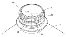
本発明に係る樹脂製容器の蓋構造の実施形態について、図面を参照して説明する。本実施形態に係る樹脂製容器の蓋構造Sは、雄ネジ部12を外周面11に有する口部10と、複数の突起部23が周方向に断続的に連なってなる雌ネジ部22を内周面21に有するキャップ20と、を有し、雄ネジ部12は、少なくとも周方向の一部で、口部10の先端から末端の間におけるネジ山数が一本である一ネジ部分13aを有する。そして、口部10の雄ネジ部12にキャップ20の雌ネジ部22を螺合させて口部10をキャップ20により巻き締めて密閉する。また、雄ネジ部12における一ネジ部分13aの下側に配置される雌ネジ部22における突起部23であって、他の突起部23の周方向の長さより周方向の長さが長い延設突起部24,25を設けてある。これにより、雌ネジ部22の押上げを防ぐ力を補強することができ、キャップ20の天面26の押し上げを抑制することができる。以下、本実施形態の蓋構造Sを、樹脂製容器としてプラスチックボトル1(以下、ボトル1と称する)に適用した例について詳細に説明する。
図1に示すように、蓋構造Sは、ボトル1の口部10と、口部10に装着するキャップ20とから構成される。口部10は雄ネジ部12を外周面11に有し、キャップ20は雌ネジ部22を内周面21に有する。そして、蓋構造Sでは、口部10の雄ネジ部12にキャップ20の雌ネジ部22を螺合させて口部10をキャップ20により巻き締めて密閉する。
なお、ボトル1は、例えば、ポリエチレン、ポリプロピレン、ポリエチレンテレフタレート等の熱可塑性樹脂を主材料として、二軸延伸ブロー成型等の延伸成形法によって一体的に成型することができる。ボトル1の容量は特に限定されず、一般的に流通している200ミリリットル~2リットル程度とすることができる。
また、ボトル1に充填させる液体は特に限定されず、例えば、飲料水、茶、果汁、コーヒー、ココア、清涼飲料水、アルコール飲料、乳飲料、スープなどの飲料や、ソースや醤油などの液体調味料などが挙げられる。なお、本実施形態における蓋構造Sは、雰囲気温度が高い場所で保管されたときに、内容物の熱膨張に加えて液中から炭酸抜けが起こることにより、ボトル1内の内圧が特に高まることとなる炭酸飲料をボトル1に充填させる場合に特に好適である。ただし、炭酸飲料でなくとも、内容物の熱膨張によりボトル1内の内圧が高まることとなるため、本実施形態における蓋構造Sは、非炭酸飲料についても好適に用いることができる。
口部10における雄ネジ部12は、その外周面11から径方向(外周面11に垂直な方向)に突出するネジ山13が周方向に螺旋状で断続的に連なったものである。そして、雄ネジ部12は、少なくとも周方向の一部において、口部10の先端から末端に間におけるネジ山13の数が一本である一ネジ部分13aを有する。
図1,2に示すように、キャップ20における雌ネジ部22は、複数の突起部23が周方向に断続的に連なってなる。そして、縦方向に並ぶ2つの突起部23の間に形成される間隙に雄ネジ部12のネジ山13が収容されるように、雄ネジ部12(ネジ山13)と雌ネジ部22(突起部23)とは相補的に形成されている。
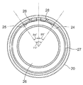
雌ネジ部22において、突起部23のうち、他の突起部23の周方向の長さより周方向の長さが長い2つの延設突起部24,25が連続して設けられている。そして、この延設突起部24,25は、口部10をキャップ20により巻き締めて密閉するときに、雄ネジ部12における一ネジ部分13aの下側(口部10の末端側)に位置するように配置されている。
なお、キャップ20により口部10を密閉状態とするのに、必ずしも、キャップ20を口部10に最大限まで巻き締めた状態(最大巻締状態)とする必要はなく、最小限必要とされる巻き締め量まで巻き締めれば(最小巻締状態)、口部10を密閉状態とすることが可能となる。つまり、最大巻締状態と最小巻締状態との間の巻き締め量であれば口部10を密閉状態とすることができる。また、本実施形態における蓋構造Sでは、最大巻締状態と最小巻締状態との間の巻き締め量の差は、口部10の外周面11を円周とするときの中心角35°の円弧の長さに相当する。
そこで、この各延設突起部24,25の長さは、口部10の外周面11を円周とするときの中心角35°の円弧の長さに相当する長さとしてある。つまり、中心角70°の円弧の範囲で延設突起部24,25が設けられた状態となっている。そして、最大巻締状態(図3参照)においては、延設突起部24が一ネジ部分13aの下側に配置され、最小巻締状態(図4参照)においては、延設突起部25が一ネジ部分13aの下側に配置される。そして、最大巻締状態と最小巻締状態の間の巻き締め量のとき(図1参照)は、両延設突起部24,25が一ネジ部分13aの下側に配置される。つまり、延設突起部24,25は、最大巻締状態から最小巻締状態にわたって、延設突起部24又は/及び延設突起部25が一ネジ部分13aの下側に配置される範囲に設けられた状態となっている。
また、図5(a)は延設突起部24が一ネジ部分13aの下側に位置した状態を示し、図5(b)は他の突起部23が一ネジ部分13aの下側に位置した状態を示す。図5(a),(b)に示すように、延設突起部24において、キャップ20の内周面21からの突出高さは、他の突起部23の突出高さより高くしてある。また、延設突起部24は、その先端縁24aを角張らせてある。なお、延設突起部25についても、延設突起部24と同様に、キャップ20の内周面21からの突出高さを、他の突起部23の突出高さより高くしてあり、その先端縁を角張らせてある。
図5,6に示すように、キャップ20の天面26の内側面26aには、口部10の外周面11をシールするアウターシール部27を突出形成してある。そして、このアウターシール部27とキャップ20の内周面21との間を接続するリブ28を、口部10をキャップ20により巻き締めて密閉するときに一ネジ部分13aと対応する部分に設けてある。より具体的には、各延設突起部24,25の上方に、それぞれリブ28を設けてある。
次に、口部10をキャップ20により巻き締めて密閉したときの状態について説明する。このとき、図1,3,4に示すように、一ネジ部分13aの下側に延設突起部24又は/及び延設突起部25が配置される。つまり、ボトル1内の内圧が高まり、キャップ20の天面26が押し上げられる状態となったときに、一ネジ部分13aが延設突起部24又は/及び延設突起部25と係合することとなる。一ネジ部分13aについては係合する雌ネジ部12の押上げを防ぐ力が通常弱くなるのであるが、本実施形態における蓋構造Sでは、係合する延設突起部24,25は周方向の長さが長く、その変形を抑制することができ、一ネジ部分13aにより雌ネジ部12の押上げが抑制される。
また、図5(a),(b)に示すように、延設突起部24において、キャップ20の内周面21からの突出高さは、他の突起部23の突出高さより高くしてあり、これにより、延設突起部24が一ネジ部分13aと当接する面積が広くなる。そして、延設突起部24は、その先端縁24aを角張らせてあり、延設突起部24が一ネジ部分13aにより強く引っかかることとなる。これらにより、雌ネジ部13の押上げが一層抑制される。なお、延設突起部25においても、延設突起部24と同形状であり、同様の作用効果を奏する。
また、アウターシール部27とキャップ20の内周面21との間を接続するリブ28を一ネジ部分13aと対応する部分に設けてあるから、キャップ20の天面26が膨張変形することを抑制することができ、これにより、キャップ20の天面26の押し上げが一層抑制される。
以上のように、本実施形態における蓋構造Sでは、一ネジ部分13aにおける雌ネジ部23の押上げを防ぐ力を補強するとともに、キャップ20の天面26が膨張変形することを抑制するから、キャップ20の天面26の押し上げを抑制することができる。このように、本実施形態における蓋構造Sでは、キャップ20の構成を変更するのみでボトル1内の密閉状態を好適に保つことができる。
〔その他の実施形態〕
最後に、本発明に係る樹脂製容器の蓋構造のその他の実施形態について説明する。なお、以下のそれぞれの実施形態で開示される構成は、矛盾が生じない限り、他の実施形態で開示される構成と組み合わせて適用することも可能である。
最後に、本発明に係る樹脂製容器の蓋構造のその他の実施形態について説明する。なお、以下のそれぞれの実施形態で開示される構成は、矛盾が生じない限り、他の実施形態で開示される構成と組み合わせて適用することも可能である。
(1)上記の実施形態では、2つの延設突起部24,25が連続して設けられた構成を例として説明した。しかし、本発明の実施形態はこれに限定されない。例えば、2つの延設突起部24,25を合わせた長さの1つの延設突起部を設けた構成としても良い。また、延設突起部24,25の長さ寸法は、樹脂製容器における一ネジ部分の周方向の長さに応じて適宜変更すればよい。
(2)上記の実施形態では、延設突起部24,25が、最大巻締状態から最小巻締状態にわたって、延設突起部24又は/及び延設突起部25が一ネジ部分13aの下側に配置される範囲に設けられた構成を例として説明した。しかし、本発明の実施形態はこれに限定されない。例えば、最大巻締状態のみ、最小巻締状態のみ、又は、最大巻締状態と最小巻締状態の間の任意の巻き締め量のときのみに、延設突起部24,25が一ネジ部分13aの下側に配置される構成としても良い。
(3)上記の実施形態では、図5(a)に示すように、延設突起部24におけるキャップ20の内周面21からの突出高さが、他の突起部23の突出高さより高く、その先端縁24aを角張らせてある構成を例として説明した。しかし、本発明の実施形態はこれに限定されない。例えば、内周面21からの突出高さは他の突起部23と同じであってもよく、また、先端縁24aは角を削った構成としても良い。なお、延設突起部25についても同様の変更が可能である。
(4)上記の実施形態では、アウターシール部27とキャップ20の内周面21との間を接続するリブ28を、一ネジ部分13aと対応する部分に設けた構成を例として説明した。しかし、本発明の実施形態はこれに限定されない。例えば、リブ28を設けない構成としても良く、また、一ネジ部分13aと対応する部分以外にもリブ28を設けた構成としても良い。
(5)その他の構成に関しても、本明細書において開示された実施形態は全ての点で例示であって、本発明の範囲はそれらによって限定されることはないと理解されるべきである。当業者であれば、本発明の趣旨を逸脱しない範囲で、適宜改変が可能であることを容易に理解できるであろう。従って、本発明の趣旨を逸脱しない範囲で改変された別の実施形態も、当然、本発明の範囲に含まれる。
本発明は、例えば液体を内部に充填させる樹脂製容器の蓋構造に利用することができる。
S 蓋構造
1 樹脂製容器
10 口部
11 外周面
12 雄ネジ部
13a 一ネジ部分
20 キャップ
21 内周面
22 雌ネジ部
23 突起部
24,25 延設突起部
24a,25a 先端縁
27 アウターシール部
28 リブ
1 樹脂製容器
10 口部
11 外周面
12 雄ネジ部
13a 一ネジ部分
20 キャップ
21 内周面
22 雌ネジ部
23 突起部
24,25 延設突起部
24a,25a 先端縁
27 アウターシール部
28 リブ
Claims (5)
- 雄ネジ部を外周面に有する口部と、
複数の突起部が周方向に断続的に連なってなる雌ネジ部を内周面に有するキャップと、を有し、
前記雄ネジ部が、少なくとも前記口部の周方向の一部において、前記口部の先端から末端の間におけるネジ山数が一本である一ネジ部分を有し、
前記口部の前記雄ネジ部に前記キャップの前記雌ネジ部を螺合させて前記口部を前記キャップにより巻き締めて密閉する樹脂製容器の蓋構造であって、
前記雄ネジ部における前記一ネジ部分の下側に配置される前記雌ネジ部における前記突起部であって、他の前記突起部の周方向の長さより周方向の長さが長い延設突起部を設けてある蓋構造。 - 前記延設突起部は、前記キャップを前記口部に最大限巻き締めた最大巻締状態から、前記口部を密閉するために最小限必要とされる量だけ前記キャップを巻き締めた最小巻締状態にわたって、前記一ネジ部分の下側に配置される範囲に設けられている請求項1に記載の蓋構造。
- 前記延設突起部の前記キャップの内周面からの突出高さを、他の前記突起部の突出高さより高くしてある請求項1又は2に記載の蓋構造。
- 前記延設突起部の先端縁を角張らせてある請求項1~3のいずれか1項に記載の蓋構造。
- 前記キャップにおける前記口部の外周面をシールするアウターシール部と前記キャップの内周面との間を接続するリブを、少なくとも前記一ネジ部分と対応する部分に設けてある請求項1~4のいずれか1項に記載の蓋構造。
Priority Applications (6)
| Application Number | Priority Date | Filing Date | Title |
|---|---|---|---|
| SG11201707785WA SG11201707785WA (en) | 2015-03-24 | 2015-03-24 | Lid assembly for resin container |
| JP2017507202A JP6595579B2 (ja) | 2015-03-24 | 2015-03-24 | 樹脂製容器の蓋構造 |
| PCT/JP2015/058840 WO2016151746A1 (ja) | 2015-03-24 | 2015-03-24 | 樹脂製容器の蓋構造 |
| ES15886299T ES2805097T3 (es) | 2015-03-24 | 2015-03-24 | Conjunto de tapa para un recipiente de resina |
| EP15886299.5A EP3275801B1 (en) | 2015-03-24 | 2015-03-24 | Lid assembly for resin container |
| TW105108670A TWI603896B (zh) | 2015-03-24 | 2016-03-21 | 樹脂容器的蓋構造 |
Applications Claiming Priority (1)
| Application Number | Priority Date | Filing Date | Title |
|---|---|---|---|
| PCT/JP2015/058840 WO2016151746A1 (ja) | 2015-03-24 | 2015-03-24 | 樹脂製容器の蓋構造 |
Publications (1)
| Publication Number | Publication Date |
|---|---|
| WO2016151746A1 true WO2016151746A1 (ja) | 2016-09-29 |
Family
ID=56978847
Family Applications (1)
| Application Number | Title | Priority Date | Filing Date |
|---|---|---|---|
| PCT/JP2015/058840 Ceased WO2016151746A1 (ja) | 2015-03-24 | 2015-03-24 | 樹脂製容器の蓋構造 |
Country Status (6)
| Country | Link |
|---|---|
| EP (1) | EP3275801B1 (ja) |
| JP (1) | JP6595579B2 (ja) |
| ES (1) | ES2805097T3 (ja) |
| SG (1) | SG11201707785WA (ja) |
| TW (1) | TWI603896B (ja) |
| WO (1) | WO2016151746A1 (ja) |
Cited By (2)
| Publication number | Priority date | Publication date | Assignee | Title |
|---|---|---|---|---|
| WO2019064450A1 (ja) * | 2017-09-28 | 2019-04-04 | サントリーホールディングス株式会社 | 内圧が陽圧となるボトルに用いるキャップ、及び、当該キャップを取り付けたボトル |
| JP2022086922A (ja) * | 2020-11-30 | 2022-06-09 | 株式会社吉野工業所 | ねじキャップ付き容器 |
Families Citing this family (3)
| Publication number | Priority date | Publication date | Assignee | Title |
|---|---|---|---|---|
| CA3001196C (en) * | 2015-10-23 | 2023-08-22 | Husky Injection Molding Systems Ltd. | Containers and closures |
| US10543960B2 (en) * | 2017-11-28 | 2020-01-28 | Thermos L.L.C. | Lid for a beverage container |
| IT202100001430A1 (it) | 2021-01-26 | 2022-07-26 | Sacmi | Tappo per contenitore. |
Citations (4)
| Publication number | Priority date | Publication date | Assignee | Title |
|---|---|---|---|---|
| US4090629A (en) * | 1977-08-22 | 1978-05-23 | International Tools (1973) Limited | Spiral lock safety closure |
| JP2004035066A (ja) * | 2002-07-04 | 2004-02-05 | Toppan Printing Co Ltd | 径歪み矯正リブ付キャップ |
| GB2476089A (en) * | 2009-12-10 | 2011-06-15 | Beeson & Sons Ltd | Container closure assembly with tamper evident ring |
| JP2013189246A (ja) * | 2012-02-14 | 2013-09-26 | Nihon Yamamura Glass Co Ltd | 樹脂製キャップ |
Family Cites Families (1)
| Publication number | Priority date | Publication date | Assignee | Title |
|---|---|---|---|---|
| US20090045158A1 (en) * | 2007-08-14 | 2009-02-19 | Alcoa Closure Systems International, Inc. | Threaded closure with internal ribs |
-
2015
- 2015-03-24 ES ES15886299T patent/ES2805097T3/es active Active
- 2015-03-24 EP EP15886299.5A patent/EP3275801B1/en active Active
- 2015-03-24 JP JP2017507202A patent/JP6595579B2/ja active Active
- 2015-03-24 SG SG11201707785WA patent/SG11201707785WA/en unknown
- 2015-03-24 WO PCT/JP2015/058840 patent/WO2016151746A1/ja not_active Ceased
-
2016
- 2016-03-21 TW TW105108670A patent/TWI603896B/zh active
Patent Citations (4)
| Publication number | Priority date | Publication date | Assignee | Title |
|---|---|---|---|---|
| US4090629A (en) * | 1977-08-22 | 1978-05-23 | International Tools (1973) Limited | Spiral lock safety closure |
| JP2004035066A (ja) * | 2002-07-04 | 2004-02-05 | Toppan Printing Co Ltd | 径歪み矯正リブ付キャップ |
| GB2476089A (en) * | 2009-12-10 | 2011-06-15 | Beeson & Sons Ltd | Container closure assembly with tamper evident ring |
| JP2013189246A (ja) * | 2012-02-14 | 2013-09-26 | Nihon Yamamura Glass Co Ltd | 樹脂製キャップ |
Cited By (7)
| Publication number | Priority date | Publication date | Assignee | Title |
|---|---|---|---|---|
| WO2019064450A1 (ja) * | 2017-09-28 | 2019-04-04 | サントリーホールディングス株式会社 | 内圧が陽圧となるボトルに用いるキャップ、及び、当該キャップを取り付けたボトル |
| CN111132908A (zh) * | 2017-09-28 | 2020-05-08 | 三得利控股株式会社 | 用于内压为正压的瓶的盖、以及安装有该盖的瓶 |
| EP3521195A4 (en) * | 2017-09-28 | 2020-07-22 | Suntory Holdings Limited | CAP INTENDED TO BE USED WITH A BOTTLE HAVING A POSITIVE INTERNAL PRESSURE, AND BOTTLE WITH A CAP ATTACHED TO IT |
| JPWO2019064450A1 (ja) * | 2017-09-28 | 2020-09-10 | サントリーホールディングス株式会社 | 内圧が陽圧となるボトルに用いるキャップ、及び、当該キャップを取り付けたボトル |
| CN111132908B (zh) * | 2017-09-28 | 2022-07-05 | 三得利控股株式会社 | 瓶 |
| JP2022086922A (ja) * | 2020-11-30 | 2022-06-09 | 株式会社吉野工業所 | ねじキャップ付き容器 |
| JP7588935B2 (ja) | 2020-11-30 | 2024-11-25 | 株式会社吉野工業所 | ねじキャップ付き容器 |
Also Published As
| Publication number | Publication date |
|---|---|
| EP3275801A4 (en) | 2018-12-19 |
| EP3275801A1 (en) | 2018-01-31 |
| ES2805097T3 (es) | 2021-02-10 |
| JPWO2016151746A1 (ja) | 2018-01-25 |
| TW201641379A (zh) | 2016-12-01 |
| TWI603896B (zh) | 2017-11-01 |
| SG11201707785WA (en) | 2017-10-30 |
| JP6595579B2 (ja) | 2019-10-23 |
| EP3275801B1 (en) | 2020-05-27 |
Similar Documents
| Publication | Publication Date | Title |
|---|---|---|
| JP6595579B2 (ja) | 樹脂製容器の蓋構造 | |
| US9676531B2 (en) | Membrane, and a neck including such membrane | |
| JP2004520233A (ja) | 使い勝手のよいキャップアセンブリのためのプラグシール | |
| US20110108509A1 (en) | Container closure | |
| WO2004110888A1 (ja) | 合成樹脂製キャップ、閉止装置、および容器詰め飲料 | |
| WO2000056616A1 (en) | Closure with seal member | |
| WO2018047711A1 (ja) | 樹脂製キャップ | |
| JP6207896B2 (ja) | プラスチックキャップ及びキャップ付ポリエステルボトル | |
| JP2004352261A (ja) | 耐内圧性とラベル貼付性とに優れたプラスチックキャップ | |
| JP6956749B2 (ja) | 内圧が陽圧となるボトル | |
| JP2016043989A (ja) | 注出口栓及び包装容器 | |
| US20120097677A1 (en) | Hermetic Container | |
| WO2015194040A1 (ja) | 樹脂製キャップ | |
| WO2020179608A1 (ja) | キャップ | |
| JP4309175B2 (ja) | プラスチックキャップ | |
| JP7811439B2 (ja) | 樹脂製キャップ | |
| JP2018020814A (ja) | 合成樹脂製キャップ | |
| KR200315375Y1 (ko) | 봉인구조를 갖는 튜브용기 뚜껑 | |
| KR20160002181U (ko) | 포장용기 뚜껑 | |
| JP2019167139A (ja) | 樹脂製キャップ及びこの樹脂製キャップと容器口部の組み合わせ | |
| AU2018288101B2 (en) | Container spout portion, resin made container having the container spout portion and preform having the container spout portion | |
| JP2018020815A (ja) | 合成樹脂製キャップ | |
| JPH0721553U (ja) | プラスチック製のねじキャップ | |
| WO2021060252A1 (ja) | キャップ | |
| KR20210105249A (ko) | 용기의 밀봉 구조 및 이를 구비한 용기 |
Legal Events
| Date | Code | Title | Description |
|---|---|---|---|
| 121 | Ep: the epo has been informed by wipo that ep was designated in this application |
Ref document number: 15886299 Country of ref document: EP Kind code of ref document: A1 |
|
| WWE | Wipo information: entry into national phase |
Ref document number: 11201707785W Country of ref document: SG |
|
| ENP | Entry into the national phase |
Ref document number: 2017507202 Country of ref document: JP Kind code of ref document: A |
|
| NENP | Non-entry into the national phase |
Ref country code: DE |