WO2016151781A1 - 加工ノズル、加工ヘッド、加工装置 - Google Patents
加工ノズル、加工ヘッド、加工装置 Download PDFInfo
- Publication number
- WO2016151781A1 WO2016151781A1 PCT/JP2015/059003 JP2015059003W WO2016151781A1 WO 2016151781 A1 WO2016151781 A1 WO 2016151781A1 JP 2015059003 W JP2015059003 W JP 2015059003W WO 2016151781 A1 WO2016151781 A1 WO 2016151781A1
- Authority
- WO
- WIPO (PCT)
- Prior art keywords
- processing
- supply path
- powder
- nozzle
- supply
- Prior art date
- Legal status (The legal status is an assumption and is not a legal conclusion. Google has not performed a legal analysis and makes no representation as to the accuracy of the status listed.)
- Ceased
Links
Images




Classifications
-
- B—PERFORMING OPERATIONS; TRANSPORTING
- B23—MACHINE TOOLS; METAL-WORKING NOT OTHERWISE PROVIDED FOR
- B23K—SOLDERING OR UNSOLDERING; WELDING; CLADDING OR PLATING BY SOLDERING OR WELDING; CUTTING BY APPLYING HEAT LOCALLY, e.g. FLAME CUTTING; WORKING BY LASER BEAM
- B23K26/00—Working by laser beam, e.g. welding, cutting or boring
- B23K26/14—Working by laser beam, e.g. welding, cutting or boring using a fluid stream, e.g. a jet of gas, in conjunction with the laser beam; Nozzles therefor
- B23K26/1462—Nozzles; Features related to nozzles
- B23K26/1464—Supply to, or discharge from, nozzles of media, e.g. gas, powder, wire
- B23K26/1476—Features inside the nozzle for feeding the fluid stream through the nozzle
-
- B—PERFORMING OPERATIONS; TRANSPORTING
- B22—CASTING; POWDER METALLURGY
- B22F—WORKING METALLIC POWDER; MANUFACTURE OF ARTICLES FROM METALLIC POWDER; MAKING METALLIC POWDER; APPARATUS OR DEVICES SPECIALLY ADAPTED FOR METALLIC POWDER
- B22F10/00—Additive manufacturing of workpieces or articles from metallic powder
- B22F10/20—Direct sintering or melting
- B22F10/25—Direct deposition of metal particles, e.g. direct metal deposition [DMD] or laser engineered net shaping [LENS]
-
- B—PERFORMING OPERATIONS; TRANSPORTING
- B22—CASTING; POWDER METALLURGY
- B22F—WORKING METALLIC POWDER; MANUFACTURE OF ARTICLES FROM METALLIC POWDER; MAKING METALLIC POWDER; APPARATUS OR DEVICES SPECIALLY ADAPTED FOR METALLIC POWDER
- B22F12/00—Apparatus or devices specially adapted for additive manufacturing; Auxiliary means for additive manufacturing; Combinations of additive manufacturing apparatus or devices with other processing apparatus or devices
- B22F12/38—Housings, e.g. machine housings
-
- B—PERFORMING OPERATIONS; TRANSPORTING
- B22—CASTING; POWDER METALLURGY
- B22F—WORKING METALLIC POWDER; MANUFACTURE OF ARTICLES FROM METALLIC POWDER; MAKING METALLIC POWDER; APPARATUS OR DEVICES SPECIALLY ADAPTED FOR METALLIC POWDER
- B22F12/00—Apparatus or devices specially adapted for additive manufacturing; Auxiliary means for additive manufacturing; Combinations of additive manufacturing apparatus or devices with other processing apparatus or devices
- B22F12/40—Radiation means
- B22F12/44—Radiation means characterised by the configuration of the radiation means
-
- B—PERFORMING OPERATIONS; TRANSPORTING
- B22—CASTING; POWDER METALLURGY
- B22F—WORKING METALLIC POWDER; MANUFACTURE OF ARTICLES FROM METALLIC POWDER; MAKING METALLIC POWDER; APPARATUS OR DEVICES SPECIALLY ADAPTED FOR METALLIC POWDER
- B22F12/00—Apparatus or devices specially adapted for additive manufacturing; Auxiliary means for additive manufacturing; Combinations of additive manufacturing apparatus or devices with other processing apparatus or devices
- B22F12/50—Means for feeding of material, e.g. heads
- B22F12/53—Nozzles
-
- B—PERFORMING OPERATIONS; TRANSPORTING
- B23—MACHINE TOOLS; METAL-WORKING NOT OTHERWISE PROVIDED FOR
- B23K—SOLDERING OR UNSOLDERING; WELDING; CLADDING OR PLATING BY SOLDERING OR WELDING; CUTTING BY APPLYING HEAT LOCALLY, e.g. FLAME CUTTING; WORKING BY LASER BEAM
- B23K26/00—Working by laser beam, e.g. welding, cutting or boring
- B23K26/14—Working by laser beam, e.g. welding, cutting or boring using a fluid stream, e.g. a jet of gas, in conjunction with the laser beam; Nozzles therefor
- B23K26/144—Working by laser beam, e.g. welding, cutting or boring using a fluid stream, e.g. a jet of gas, in conjunction with the laser beam; Nozzles therefor the fluid stream containing particles, e.g. powder
-
- B—PERFORMING OPERATIONS; TRANSPORTING
- B23—MACHINE TOOLS; METAL-WORKING NOT OTHERWISE PROVIDED FOR
- B23K—SOLDERING OR UNSOLDERING; WELDING; CLADDING OR PLATING BY SOLDERING OR WELDING; CUTTING BY APPLYING HEAT LOCALLY, e.g. FLAME CUTTING; WORKING BY LASER BEAM
- B23K26/00—Working by laser beam, e.g. welding, cutting or boring
- B23K26/34—Laser welding for purposes other than joining
- B23K26/342—Build-up welding
-
- B—PERFORMING OPERATIONS; TRANSPORTING
- B29—WORKING OF PLASTICS; WORKING OF SUBSTANCES IN A PLASTIC STATE IN GENERAL
- B29C—SHAPING OR JOINING OF PLASTICS; SHAPING OF MATERIAL IN A PLASTIC STATE, NOT OTHERWISE PROVIDED FOR; AFTER-TREATMENT OF THE SHAPED PRODUCTS, e.g. REPAIRING
- B29C64/00—Additive manufacturing, i.e. manufacturing of three-dimensional [3D] objects by additive deposition, additive agglomeration or additive layering, e.g. by 3D printing, stereolithography or selective laser sintering
- B29C64/10—Processes of additive manufacturing
- B29C64/141—Processes of additive manufacturing using only solid materials
-
- B—PERFORMING OPERATIONS; TRANSPORTING
- B29—WORKING OF PLASTICS; WORKING OF SUBSTANCES IN A PLASTIC STATE IN GENERAL
- B29C—SHAPING OR JOINING OF PLASTICS; SHAPING OF MATERIAL IN A PLASTIC STATE, NOT OTHERWISE PROVIDED FOR; AFTER-TREATMENT OF THE SHAPED PRODUCTS, e.g. REPAIRING
- B29C64/00—Additive manufacturing, i.e. manufacturing of three-dimensional [3D] objects by additive deposition, additive agglomeration or additive layering, e.g. by 3D printing, stereolithography or selective laser sintering
- B29C64/10—Processes of additive manufacturing
- B29C64/141—Processes of additive manufacturing using only solid materials
- B29C64/153—Processes of additive manufacturing using only solid materials using layers of powder being selectively joined, e.g. by selective laser sintering or melting
-
- B—PERFORMING OPERATIONS; TRANSPORTING
- B29—WORKING OF PLASTICS; WORKING OF SUBSTANCES IN A PLASTIC STATE IN GENERAL
- B29C—SHAPING OR JOINING OF PLASTICS; SHAPING OF MATERIAL IN A PLASTIC STATE, NOT OTHERWISE PROVIDED FOR; AFTER-TREATMENT OF THE SHAPED PRODUCTS, e.g. REPAIRING
- B29C64/00—Additive manufacturing, i.e. manufacturing of three-dimensional [3D] objects by additive deposition, additive agglomeration or additive layering, e.g. by 3D printing, stereolithography or selective laser sintering
- B29C64/20—Apparatus for additive manufacturing; Details thereof or accessories therefor
- B29C64/205—Means for applying layers
- B29C64/209—Heads; Nozzles
-
- B—PERFORMING OPERATIONS; TRANSPORTING
- B29—WORKING OF PLASTICS; WORKING OF SUBSTANCES IN A PLASTIC STATE IN GENERAL
- B29C—SHAPING OR JOINING OF PLASTICS; SHAPING OF MATERIAL IN A PLASTIC STATE, NOT OTHERWISE PROVIDED FOR; AFTER-TREATMENT OF THE SHAPED PRODUCTS, e.g. REPAIRING
- B29C67/00—Shaping techniques not covered by groups B29C39/00 - B29C65/00, B29C70/00 or B29C73/00
-
- B—PERFORMING OPERATIONS; TRANSPORTING
- B33—ADDITIVE MANUFACTURING TECHNOLOGY
- B33Y—ADDITIVE MANUFACTURING, i.e. MANUFACTURING OF THREE-DIMENSIONAL [3D] OBJECTS BY ADDITIVE DEPOSITION, ADDITIVE AGGLOMERATION OR ADDITIVE LAYERING, e.g. BY 3D PRINTING, STEREOLITHOGRAPHY OR SELECTIVE LASER SINTERING
- B33Y10/00—Processes of additive manufacturing
-
- B—PERFORMING OPERATIONS; TRANSPORTING
- B33—ADDITIVE MANUFACTURING TECHNOLOGY
- B33Y—ADDITIVE MANUFACTURING, i.e. MANUFACTURING OF THREE-DIMENSIONAL [3D] OBJECTS BY ADDITIVE DEPOSITION, ADDITIVE AGGLOMERATION OR ADDITIVE LAYERING, e.g. BY 3D PRINTING, STEREOLITHOGRAPHY OR SELECTIVE LASER SINTERING
- B33Y30/00—Apparatus for additive manufacturing; Details thereof or accessories therefor
-
- B—PERFORMING OPERATIONS; TRANSPORTING
- B22—CASTING; POWDER METALLURGY
- B22F—WORKING METALLIC POWDER; MANUFACTURE OF ARTICLES FROM METALLIC POWDER; MAKING METALLIC POWDER; APPARATUS OR DEVICES SPECIALLY ADAPTED FOR METALLIC POWDER
- B22F12/00—Apparatus or devices specially adapted for additive manufacturing; Auxiliary means for additive manufacturing; Combinations of additive manufacturing apparatus or devices with other processing apparatus or devices
- B22F12/22—Driving means
- B22F12/226—Driving means for rotary motion
-
- Y—GENERAL TAGGING OF NEW TECHNOLOGICAL DEVELOPMENTS; GENERAL TAGGING OF CROSS-SECTIONAL TECHNOLOGIES SPANNING OVER SEVERAL SECTIONS OF THE IPC; TECHNICAL SUBJECTS COVERED BY FORMER USPC CROSS-REFERENCE ART COLLECTIONS [XRACs] AND DIGESTS
- Y02—TECHNOLOGIES OR APPLICATIONS FOR MITIGATION OR ADAPTATION AGAINST CLIMATE CHANGE
- Y02P—CLIMATE CHANGE MITIGATION TECHNOLOGIES IN THE PRODUCTION OR PROCESSING OF GOODS
- Y02P10/00—Technologies related to metal processing
- Y02P10/25—Process efficiency
Definitions
- the present invention relates to a machining nozzle, a machining head, and a machining apparatus.
- Patent Document 1 discloses a technique for supplying a plurality of types of powders while changing the distribution rate.
- Table 1 discloses a technique for gradually changing the powder mixing ratio from the first layer to the fifth layer.
- Paragraph 0058 discloses that the concentration position of the powder flow 4 discharged from the gap at the tip of the inner nozzle 31 and the outer nozzle 32 changes as the inner nozzle 31 moves up and down.
- the powder is injected from only one supply path 41 in both the configuration of FIG. 5 and the configuration of FIG. That is, only one type of powder can be supplied at a time. For this reason, when a plurality of types of powders are to be supplied to the processed surface, they must be mixed and supplied in advance, causing segregation during the supply, and the desired composition cannot be realized.
- An object of the present invention is to provide a technique for solving the above-described problems.
- a processing nozzle comprises: A processing nozzle for injecting a powder material to a molten pool formed on a processing surface by laser light, An inner casing constituting an optical path through which the laser beam passes; An outer casing disposed through a gap as the first supply path of the inner casing and the powder material; With A second powder supply path and a third supply path having a diameter different from that of the second supply path are provided inside the outer casing.
- a machining head comprises: It includes the processing nozzle described above and a focusing device for focusing the laser beam.
- a processing apparatus includes: The above processing head; A material supply unit for supplying the powder material to the processing head; It is provided with.
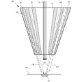
- a processing nozzle 100 as a first embodiment of the present invention will be described with reference to FIGS. 1 to 4.
- the processing nozzle 100 is a nozzle for injecting the powder material 130 to the molten pool 151 formed on the processing surface 150 by the laser beam 110.
- the processing nozzle 100 includes an inner casing 101 that constitutes an optical path 111 through which the laser light 110 passes, and an outer casing 102 that is disposed via a gap as the supply path 103 for the inner casing 101 and the powder material 130. It is equipped with.
- powder supply paths 121 and 122 are further provided in the outer casing 102.
- the powder supply paths 121 and 122 have different diameters.
- three supply paths 121 and three supply paths 122 are provided.
- the outer casing 102 has a cylindrical shape, and the supply path 121 and the supply path 122 are alternately provided in a circumferential shape inside the outer casing 102.
- FIG. 2 is an end view showing the downstream end of the processing nozzle 100. As shown in FIG. 2, at the downstream end of the processing nozzle 100, an opening 201 of the optical path 111, an opening 203 of the supply path 103, an opening 221 of the supply path 121, and an opening 222 of the supply path 122 Is provided.
- FIG. 3 is a cross-sectional view taken along the line AA in FIG.
- the powder material 131 supplied from the ring-shaped supply path 103 forms a very thin flow in a ring shape and converges in a narrow range.
- more powder material than the supply path 103 is supplied to the processing surface 150 from the six supply paths 121 and 122 arranged on the circumference.
- the supply path 121 is formed to have a diameter larger than that of the supply path 122, and more powder material is supplied from the supply path 121 to the processing surface 150 than the supply path 122.
- the powder material is supplied by changing the one used among these supply channels. For example, when performing high-definition modeling, the powder material is accurately supplied from one point toward the other using only the supply path 103.
- Laminating a plurality of different materials means, for example, laminating an adhesion layer on copper (base material) and then laminating iron. Further, by supplying powders having the same material but different particle diameters using different supply paths, it is possible to perform modeling with accuracy and speed according to the modeling conditions.
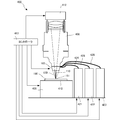
- the optical processing apparatus 400 provided with the processing nozzle 100 will be described with reference to FIG.
- the optical processing apparatus 400 is an apparatus that generates a three-dimensional shaped object (or overlay welding) by melting a material with heat generated by collected light.
- the optical processing apparatus 400 includes a light source 412, a stage 405, material storage devices 421 to 423, material supply units 424 to 426, a processing head 408, and a control unit 413.
- a laser light source is used as the light source 412, but an LED, a halogen lamp, or a xenon lamp can be used. Further, for example, an electron beam may be used.
- Stage 405 is an X stage, an XY stage, or an XYZ stage.
- the material storage devices 421 to 423 supply a carrier gas containing a material to the processing nozzle 100 via the material supply units 424 to 426.
- the material is particles such as metal particles and resin particles.
- the carrier gas is an inert gas, and for example, argon gas, nitrogen gas, helium gas, or the like can be used.
- the processing head 408 focuses the laser light from the light source 412 by an optical system including a lens or the like provided therein, and a processing nozzle 100 is attached to the downstream end thereof.
- the controller 413 inputs modeling conditions such as fine writing / bold writing and the shape of the modeled object, and according to the input modeling conditions, the output value of the laser beam from the light source 412, the position and orientation of the processing head 408, the stage 405 While changing a position etc., the processing nozzle 100 is controlled and a powder spot shape is changed.
- the controller 413 controls the material supply units 424 to 426 to control the type and amount of material injected from the nozzle 100.
- FIG. 5 is a cross-sectional view for explaining the configuration of the machining nozzle 500 according to the present embodiment.
- the processing nozzle 500 according to the present embodiment is different from the first embodiment in that it has flappers 501 and 502. Since other configurations and operations are the same as those of the first embodiment, the same configurations and operations are denoted by the same reference numerals, and detailed description thereof is omitted.
- the flow of the powder material discharged from the supply paths 121 and 122 can be changed by the flappers 501 and 502. That is, the powder material discharged from the supply path 121 can be supplied to the powder spot 511, and the powder material discharged from the supply path 122 can be supplied to the powder spot 512.
- each of the powder spots 511 and 512 has a lower temperature than the molten pool 151 of the processing surface 150. It has become.
- the flappers 501 and 502 are controlled so that the respective powder materials are supplied to the powder spots 511 and 512 that match the melting temperature of each powder material.
- FIG. 6 is a perspective view for explaining the configuration of the machining nozzle 600 according to the present embodiment.
- the processing nozzle 600 according to the present embodiment is different from the first embodiment in that it includes a rotation unit 602 that rotates the outer casing 102 in the rotation direction 601 with respect to the inner casing 101. Since other configurations and operations are the same as those of the first embodiment, the same configurations and operations are denoted by the same reference numerals, and detailed description thereof is omitted.
- the outer casing 102 can be rotated in accordance with the direction (scanning direction) 651 in which the molten pool 151 travels on the processing surface 150. That is, the arrangement of the supply paths 121 and 122 provided in the outer casing 102 with respect to the molten pool 151 can be changed according to the scanning direction 651. For example, when it is desired to supply a large amount of powder material in the scanning direction 651 of the molten pool 151, the outer casing 102 may be rotated 180 degrees from the state shown in FIG. That is, if two of the three supply passages 121 are arranged in front of the molten pool 151, the amount of powder material supplied to the front increases compared to the rear. Further, for example, when it is desired to supply a large amount of powder material to be supplied using the supply path 122 to the rear of the molten pool 151 in the scanning direction 651, the outer casing 102 is rotated 180 degrees from the state of FIG. Good.
Landscapes
- Engineering & Computer Science (AREA)
- Materials Engineering (AREA)
- Chemical & Material Sciences (AREA)
- Physics & Mathematics (AREA)
- Optics & Photonics (AREA)
- Manufacturing & Machinery (AREA)
- Mechanical Engineering (AREA)
- Plasma & Fusion (AREA)
- Toxicology (AREA)
- General Health & Medical Sciences (AREA)
- Health & Medical Sciences (AREA)
- Laser Beam Processing (AREA)
- Powder Metallurgy (AREA)
- Welding Or Cutting Using Electron Beams (AREA)
Abstract
Description
レーザ光によって加工面上に形成された溶融プールに対して粉体材料を射出するための加工ノズルであって、
前記レーザ光が通過する光経路を構成する内側筐体と、
前記内側筐体と粉体材料の第1供給路としての間隙を介して配置された外側筐体と、
を備え、
前記外側筐体内部に、粉体の第2供給路と、前記第2供給路と異なる径を有する第3供給路とを備えた。
上述の加工ノズルと、前記レーザ光を集束させる集束装置と、を含むことを特徴とする。
上述の加工ヘッドと、
前記加工ヘッドに前記粉体材料を供給する材料供給部と、
を備えたことを特徴とする。
本発明の第1実施形態としての加工ノズル100について、図1乃至図4を用いて説明する。加工ノズル100は、レーザ光110によって加工面150上に形成された溶融プール151に対して粉体材料130を射出するためのノズルである。
次に本発明の第2実施形態に係る加工ノズル500について、図5を用いて説明する。図5は、本実施形態に係る加工ノズル500の構成を説明するための断面図である。本実施形態に係る加工ノズル500は、上記第1実施形態と比べると、フラッパ501、502を有する点で異なる。その他の構成及び動作は、第1実施形態と同様であるため、同じ構成及び動作については同じ符号を付してその詳しい説明を省略する。
次に本発明の第3実施形態に係る加工ノズル600について、図6を用いて説明する。図6は、本実施形態に係る加工ノズル600の構成を説明するための斜視図である。本実施形態に係る加工ノズル600は、上記第1実施形態と比べると、内側筐体101に対して外側筐体102を回転方向601に回動させる回動部602を有する点で異なる。その他の構成及び動作は、第1実施形態と同様であるため、同じ構成及び動作については同じ符号を付してその詳しい説明を省略する。
以上、実施形態を参照して本願発明を説明したが、本願発明は上記実施形態に限定されるものではない。本願発明の構成や詳細には、本願発明のスコープ内で当業者が理解し得る様々な変更をすることができる。また、それぞれの実施形態に含まれる別々の特徴を如何様に組み合わせたシステムまたは装置も、本発明の範疇に含まれる。
Claims (6)
- レーザ光によって加工面上に形成された溶融プールに対して粉体材料を射出するための加工ノズルであって、
前記レーザ光が通過する光経路を構成する内側筐体と、
前記内側筐体と粉体材料の第1供給路としての間隙を介して配置された外側筐体と、
を備え、
前記外側筐体内部に、粉体の第2供給路と、前記第2供給路と異なる径を有する第3供給路とを備えたことを特徴とする加工ノズル。 - 前記外側筐体は、円筒形状であって、
前記第2供給路と前記第3供給路とは、それぞれ少なくとも2つ備え、前記外側筐体内部において、周状に、交互に設けられたことを特徴とする請求項1に記載の加工ノズル。 - 前記外側筐体と前記加工面との間に、前記第1、第2粉体供給路から吐出された粉体材料の射出方向を変更するフラッパをさらに設けたことを特徴とする請求項1または2に記載の加工ノズル。
- 前記外側筐体を回転する回転手段をさらに備えたことを特徴とする請求項1、2または3に記載の加工ノズル。
- 請求項1乃至4のいずれか1項に記載の加工ノズルと、
前記レーザ光を集束させる集束装置と、
を含むことを特徴とする加工ヘッド。 - 請求項5に記載の加工ヘッドと、
前記加工ヘッドに前記粉体材料を供給する材料供給部と、
を備えたことを特徴とする加工装置。
Priority Applications (4)
| Application Number | Priority Date | Filing Date | Title |
|---|---|---|---|
| EP15886334.0A EP3159094B1 (en) | 2015-03-24 | 2015-03-24 | Processing nozzle, processing head, processing device |
| US15/119,350 US20170050268A1 (en) | 2015-03-24 | 2015-03-24 | Processing nozzle, processing head, and machining apparatus |
| JP2016510887A JP6092467B2 (ja) | 2015-03-24 | 2015-03-24 | 加工ノズル、加工ヘッド、加工装置 |
| PCT/JP2015/059003 WO2016151781A1 (ja) | 2015-03-24 | 2015-03-24 | 加工ノズル、加工ヘッド、加工装置 |
Applications Claiming Priority (1)
| Application Number | Priority Date | Filing Date | Title |
|---|---|---|---|
| PCT/JP2015/059003 WO2016151781A1 (ja) | 2015-03-24 | 2015-03-24 | 加工ノズル、加工ヘッド、加工装置 |
Publications (1)
| Publication Number | Publication Date |
|---|---|
| WO2016151781A1 true WO2016151781A1 (ja) | 2016-09-29 |
Family
ID=56978816
Family Applications (1)
| Application Number | Title | Priority Date | Filing Date |
|---|---|---|---|
| PCT/JP2015/059003 Ceased WO2016151781A1 (ja) | 2015-03-24 | 2015-03-24 | 加工ノズル、加工ヘッド、加工装置 |
Country Status (4)
| Country | Link |
|---|---|
| US (1) | US20170050268A1 (ja) |
| EP (1) | EP3159094B1 (ja) |
| JP (1) | JP6092467B2 (ja) |
| WO (1) | WO2016151781A1 (ja) |
Cited By (12)
| Publication number | Priority date | Publication date | Assignee | Title |
|---|---|---|---|---|
| IT201600103310A1 (it) * | 2016-10-14 | 2018-04-14 | Prima Ind Spa | Macchina operatrice laser per la produzione additiva tramite trattamento termico laser, in particolare fusione, e relativo procedimento |
| JP6362797B1 (ja) * | 2016-12-28 | 2018-07-25 | 三菱電機株式会社 | 合金成形品の製造方法 |
| CN110355364A (zh) * | 2018-03-26 | 2019-10-22 | 技术研究组合次世代3D积层造形技术综合开发机构 | 喷嘴及层叠造型装置 |
| WO2020250462A1 (ja) * | 2019-06-11 | 2020-12-17 | 三菱重工工作機械株式会社 | 三次元積層装置および方法 |
| WO2020250464A1 (ja) * | 2019-06-11 | 2020-12-17 | 三菱重工工作機械株式会社 | 表面加工装置および方法並びに三次元積層装置 |
| WO2021020011A1 (ja) * | 2019-07-31 | 2021-02-04 | 技術研究組合次世代3D積層造形技術総合開発機構 | ノズル及び積層造形装置 |
| JP2023529229A (ja) * | 2020-06-15 | 2023-07-07 | ローベルト ボツシユ ゲゼルシヤフト ミツト ベシユレンクテル ハフツング | 摩擦制動体を製造する方法、および摩擦制動体を製造する装置 |
| JP2024016853A (ja) * | 2020-03-26 | 2024-02-07 | 株式会社プロテリアル | 混合粉末の製造方法、混合粉末の製造装置、付加製造方法および付加製造装置 |
| JP7473719B1 (ja) | 2023-04-28 | 2024-04-23 | シェンシー テクノロジー (シャンハイ) カンパニー リミテッド | 合金ターゲット材料の製造装置及び製造方法 |
| WO2024156620A1 (de) * | 2023-01-27 | 2024-08-02 | TRUMPF Laser- und Systemtechnik AG | Strahldüse mit einem pulverabschnitt und einem vorschubabschnitt |
| WO2024202209A1 (ja) * | 2023-03-31 | 2024-10-03 | 株式会社荏原製作所 | 造形ノズル |
| US12350756B2 (en) | 2016-10-14 | 2025-07-08 | Prima Industrie S.P.A | Laser operating machine for additive manufacturing by laser thermal treatment, in particular by fusion, and corresponding method |
Families Citing this family (18)
| Publication number | Priority date | Publication date | Assignee | Title |
|---|---|---|---|---|
| GB2521386A (en) | 2013-12-18 | 2015-06-24 | Ibm | Improvements in 3D printing |
| JP6801173B2 (ja) * | 2015-10-29 | 2020-12-16 | セイコーエプソン株式会社 | 三次元構造物の製造方法、その製造装置及びその制御プログラム |
| US10150249B2 (en) * | 2015-12-29 | 2018-12-11 | Western Digital Technologies, Inc. | Dual head extruder for three-dimensional additive printer |
| US10150239B2 (en) | 2015-12-29 | 2018-12-11 | Western Digital Technologies, Inc. | Extruder for three-dimensional additive printer |
| WO2018022107A1 (en) * | 2016-07-29 | 2018-02-01 | Hewlett-Packard Development Company, L.P. | Laser melting of build materials |
| CN107671981B (zh) * | 2017-10-20 | 2019-12-27 | 龙泉市金宏瓷业有限公司 | 一种陶瓷3d打印机喷嘴多级控制机构及控制方法 |
| US10500788B2 (en) * | 2017-11-07 | 2019-12-10 | Thermwood Corporation | Apparatus and methods for additive manufacturing at ambient temperature |
| CN107839055B (zh) * | 2017-11-20 | 2019-05-21 | 龙泉市金宏瓷业有限公司 | 陶瓷打印机喷头 |
| US11426818B2 (en) | 2018-08-10 | 2022-08-30 | The Research Foundation for the State University | Additive manufacturing processes and additively manufactured products |
| KR102205851B1 (ko) * | 2018-12-26 | 2021-01-20 | 한국해양대학교 산학협력단 | 폐쇄형 기포를 갖는 다공 금속용 3차원 프린터 및 이를 이용한 3차원 프린팅 방법 |
| FR3091195B1 (fr) * | 2018-12-28 | 2022-10-14 | Fives Machining | Tete d’impression 3d par projection de poudre |
| US11219951B2 (en) | 2019-07-03 | 2022-01-11 | Directed Metal 3D, S.L. | Multi-mode laser device for metal manufacturing applications |
| DE102019124518B4 (de) * | 2019-09-12 | 2025-07-31 | Trumpf Laser- Und Systemtechnik Gmbh | Materialabscheidungseinheit mit mehrfacher Materialfokuszone sowie Verfahren zum Auftragschweißen |
| FR3118598B1 (fr) * | 2021-01-04 | 2023-06-23 | Sotimeco | Tete d’impression 3d a laser |
| JP7486440B2 (ja) * | 2021-01-14 | 2024-05-17 | 株式会社荏原製作所 | Am装置に使用されるdedノズルおよびdedノズルに着脱可能なアダプタ |
| JP7701391B2 (ja) * | 2021-01-29 | 2025-07-01 | ニデックマシンツール株式会社 | シールドガス噴出装置、及び加工装置 |
| DE102021122972A1 (de) | 2021-09-06 | 2023-03-09 | Rheinisch-Westfälische Technische Hochschule (RWTH) Aachen, Körperschaft des öffentlichen Rechts | Düsenvorrichtung und Verfahren zum Laserauftragsschweißen |
| KR102678642B1 (ko) * | 2021-11-29 | 2024-06-27 | 한국전자기술연구원 | 금속 3d프린터용 금속분말 주입장치 및 이를 이용한 금속 3d프린터 |
Citations (4)
| Publication number | Priority date | Publication date | Assignee | Title |
|---|---|---|---|---|
| JP2007222869A (ja) * | 2006-02-22 | 2007-09-06 | General Electric Co <Ge> | レーザネットシェイプ製造法のためのノズル |
| JP2009505812A (ja) * | 2005-08-23 | 2009-02-12 | ハードウェア プロプライエタリー リミテッド | 粉体放出ノズル |
| JP2012125772A (ja) * | 2010-12-13 | 2012-07-05 | Hitachi Ltd | レーザ加工ヘッド及び肉盛溶接方法 |
| EP2502729A1 (en) * | 2011-03-25 | 2012-09-26 | BAE Systems Plc | Additive layer manufacturing |
Family Cites Families (36)
| Publication number | Priority date | Publication date | Assignee | Title |
|---|---|---|---|---|
| US3851604A (en) * | 1971-05-18 | 1974-12-03 | E Seifert | Device for metering granular material |
| US4467171A (en) * | 1982-09-30 | 1984-08-21 | The United States Of America As Represented By The United States Department Of Energy | Laser cutting nozzle |
| US5043548A (en) * | 1989-02-08 | 1991-08-27 | General Electric Company | Axial flow laser plasma spraying |
| JPH04120259A (ja) * | 1990-09-10 | 1992-04-21 | Agency Of Ind Science & Technol | レーザ溶射法による機器・部材の製造方法および装置 |
| DE4120790A1 (de) * | 1991-06-24 | 1993-01-14 | Verkehrswesen Hochschule | Duese zum oberflaechenbehandeln metallischer werkstuecke |
| FR2685922B1 (fr) * | 1992-01-07 | 1995-03-24 | Strasbourg Elec | Buse coaxiale de traitement superficiel sous irradiation laser, avec apport de materiaux sous forme de poudre. |
| US5477026A (en) * | 1994-01-27 | 1995-12-19 | Chromalloy Gas Turbine Corporation | Laser/powdered metal cladding nozzle |
| US5837960A (en) * | 1995-08-14 | 1998-11-17 | The Regents Of The University Of California | Laser production of articles from powders |
| US5961862A (en) * | 1995-11-30 | 1999-10-05 | The Regents Of The University Of California | Deposition head for laser |
| US6127651A (en) * | 1996-04-29 | 2000-10-03 | Westinghouse Electric Company Llc | Welding apparatus and method |
| US6046426A (en) * | 1996-07-08 | 2000-04-04 | Sandia Corporation | Method and system for producing complex-shape objects |
| US5993554A (en) * | 1998-01-22 | 1999-11-30 | Optemec Design Company | Multiple beams and nozzles to increase deposition rate |
| DE19909390C1 (de) * | 1999-03-04 | 2000-11-09 | Fraunhofer Ges Forschung | Bearbeitungskopf und Verfahren zur Oberflächenbearbeitung von Werkstücken mittels Laserstrahl |
| US6388227B1 (en) * | 1999-07-15 | 2002-05-14 | Plasma Laser Technologies Ltd. | Combined laser and plasma-arc processing torch and method |
| DE19935274C1 (de) * | 1999-07-27 | 2001-01-25 | Fraunhofer Ges Forschung | Vorrichtung und Verfahren zur Herstellung von Bauteilen aus einer Werkstoffkombination |
| US6534745B1 (en) * | 1999-09-27 | 2003-03-18 | Mathew T. J. Lowney | Nozzle particularly suited to direct metal deposition |
| EP1234625A1 (de) * | 2001-02-21 | 2002-08-28 | Trumpf Werkzeugmaschinen GmbH + Co. KG | Verfahren und Vorrichtung zur Herstellung eines Formkörpers durch selektives Laserschmelzen |
| US6894247B2 (en) * | 2002-07-26 | 2005-05-17 | Honeywell International, Inc. | Powder feed splitter for hand-held laser powder fusion welding torch |
| JP4038724B2 (ja) * | 2003-06-30 | 2008-01-30 | トヨタ自動車株式会社 | レーザクラッド加工装置およびレーザクラッド加工方法 |
| ITTV20030155A1 (it) * | 2003-12-05 | 2005-06-06 | Lzh Laser Zentrum Hannover E V | Metodo e apparecchiatura migliorati per la sinterizzazione di materiali inorganici e prodotti cosi' ottenuti. |
| US7030337B2 (en) * | 2003-12-19 | 2006-04-18 | Honeywell International, Inc. | Hand-held laser welding wand having removable filler media delivery extension tips |
| JP4299157B2 (ja) * | 2004-02-03 | 2009-07-22 | トヨタ自動車株式会社 | 粉末金属肉盛ノズル |
| EP1759791A1 (en) * | 2005-09-05 | 2007-03-07 | Nederlandse Organisatie voor toegepast- natuurwetenschappelijk onderzoek TNO | Apparatus and method for building a three-dimensional article |
| US7458765B2 (en) * | 2005-09-23 | 2008-12-02 | Fraunhofer Usa | Diamond hard coating of ferrous substrates |
| US8629368B2 (en) * | 2006-01-30 | 2014-01-14 | Dm3D Technology, Llc | High-speed, ultra precision manufacturing station that combines direct metal deposition and EDM |
| DE102007043146B4 (de) * | 2007-09-05 | 2013-06-06 | Fraunhofer-Gesellschaft zur Förderung der angewandten Forschung e.V. | Bearbeitungskopf mit integrierter Pulverzuführung zum Auftragsschweißen mit Laserstrahlung |
| US8800480B2 (en) * | 2007-10-10 | 2014-08-12 | Ronald Peter Whitfield | Laser cladding device with an improved nozzle |
| GB2465950B (en) * | 2007-10-10 | 2012-10-03 | Ronald Peter Whitfield | Laser cladding device with an improved nozzle |
| US8505414B2 (en) * | 2008-06-23 | 2013-08-13 | Stanley Black & Decker, Inc. | Method of manufacturing a blade |
| JP5292256B2 (ja) * | 2009-10-20 | 2013-09-18 | 株式会社日立製作所 | レーザ加工ヘッド、及びレーザ肉盛方法 |
| GB2476835B (en) * | 2010-01-12 | 2012-02-01 | Rolls Royce Plc | Spray nozzle |
| US8769833B2 (en) * | 2010-09-10 | 2014-07-08 | Stanley Black & Decker, Inc. | Utility knife blade |
| EP2688730A1 (en) * | 2011-03-25 | 2014-01-29 | BAE Systems Plc. | Additive layer manufacturing |
| WO2013174449A1 (en) * | 2012-05-25 | 2013-11-28 | European Space Agency | Multi-wire feeder method and system for alloy sample formation and additive manufacturing |
| US9174388B2 (en) * | 2012-08-16 | 2015-11-03 | Stratasys, Inc. | Draw control for extrusion-based additive manufacturing systems |
| FR3008637B1 (fr) * | 2013-07-17 | 2015-08-14 | Snecma | Cloche de protection pour une buse de projection lors d'un procede de rechargement |
-
2015
- 2015-03-24 US US15/119,350 patent/US20170050268A1/en not_active Abandoned
- 2015-03-24 EP EP15886334.0A patent/EP3159094B1/en active Active
- 2015-03-24 WO PCT/JP2015/059003 patent/WO2016151781A1/ja not_active Ceased
- 2015-03-24 JP JP2016510887A patent/JP6092467B2/ja active Active
Patent Citations (4)
| Publication number | Priority date | Publication date | Assignee | Title |
|---|---|---|---|---|
| JP2009505812A (ja) * | 2005-08-23 | 2009-02-12 | ハードウェア プロプライエタリー リミテッド | 粉体放出ノズル |
| JP2007222869A (ja) * | 2006-02-22 | 2007-09-06 | General Electric Co <Ge> | レーザネットシェイプ製造法のためのノズル |
| JP2012125772A (ja) * | 2010-12-13 | 2012-07-05 | Hitachi Ltd | レーザ加工ヘッド及び肉盛溶接方法 |
| EP2502729A1 (en) * | 2011-03-25 | 2012-09-26 | BAE Systems Plc | Additive layer manufacturing |
Non-Patent Citations (1)
| Title |
|---|
| See also references of EP3159094A4 * |
Cited By (26)
| Publication number | Priority date | Publication date | Assignee | Title |
|---|---|---|---|---|
| IT201600103310A1 (it) * | 2016-10-14 | 2018-04-14 | Prima Ind Spa | Macchina operatrice laser per la produzione additiva tramite trattamento termico laser, in particolare fusione, e relativo procedimento |
| WO2018069808A1 (en) * | 2016-10-14 | 2018-04-19 | Prima Industrie S.P.A. | Laser operating machine for additive manufacturing by laser thermal treatment, in particular by fusion, and corresponding method |
| US12350756B2 (en) | 2016-10-14 | 2025-07-08 | Prima Industrie S.P.A | Laser operating machine for additive manufacturing by laser thermal treatment, in particular by fusion, and corresponding method |
| JP6362797B1 (ja) * | 2016-12-28 | 2018-07-25 | 三菱電機株式会社 | 合金成形品の製造方法 |
| US10702919B2 (en) | 2016-12-28 | 2020-07-07 | Mitsubishi Electric Corporation | Method for manufacturing alloy molded product |
| CN110355364A (zh) * | 2018-03-26 | 2019-10-22 | 技术研究组合次世代3D积层造形技术综合开发机构 | 喷嘴及层叠造型装置 |
| JP7274948B2 (ja) | 2019-06-11 | 2023-05-17 | ニデックマシンツール株式会社 | 三次元積層装置および方法 |
| WO2020250464A1 (ja) * | 2019-06-11 | 2020-12-17 | 三菱重工工作機械株式会社 | 表面加工装置および方法並びに三次元積層装置 |
| WO2020250462A1 (ja) * | 2019-06-11 | 2020-12-17 | 三菱重工工作機械株式会社 | 三次元積層装置および方法 |
| US12409497B2 (en) | 2019-06-11 | 2025-09-09 | Mitsubishi Heavy Industries Machine Tool Co., Ltd. | Three-dimensional deposition device and method |
| CN113365777A (zh) * | 2019-06-11 | 2021-09-07 | 三菱重工工作机械株式会社 | 表面加工装置、方法及三维层叠装置 |
| JP2020199536A (ja) * | 2019-06-11 | 2020-12-17 | 三菱重工工作機械株式会社 | 三次元積層装置および方法 |
| JP7184713B2 (ja) | 2019-07-31 | 2022-12-06 | 技術研究組合次世代3D積層造形技術総合開発機構 | ノズル及び積層造形装置 |
| JP2021024111A (ja) * | 2019-07-31 | 2021-02-22 | 技術研究組合次世代3D積層造形技術総合開発機構 | ノズル及び積層造形装置 |
| WO2021020011A1 (ja) * | 2019-07-31 | 2021-02-04 | 技術研究組合次世代3D積層造形技術総合開発機構 | ノズル及び積層造形装置 |
| US12365033B2 (en) | 2019-07-31 | 2025-07-22 | Shibaura Machine Co., Ltd. | Nozzle and additive manufacturing apparatus |
| JP2024016853A (ja) * | 2020-03-26 | 2024-02-07 | 株式会社プロテリアル | 混合粉末の製造方法、混合粉末の製造装置、付加製造方法および付加製造装置 |
| JP7715179B2 (ja) | 2020-03-26 | 2025-07-30 | 株式会社プロテリアル | 混合粉末の製造方法、混合粉末の製造装置、付加製造方法および付加製造装置 |
| JP2023529229A (ja) * | 2020-06-15 | 2023-07-07 | ローベルト ボツシユ ゲゼルシヤフト ミツト ベシユレンクテル ハフツング | 摩擦制動体を製造する方法、および摩擦制動体を製造する装置 |
| JP7554540B2 (ja) | 2020-06-15 | 2024-09-20 | ローベルト ボツシユ ゲゼルシヤフト ミツト ベシユレンクテル ハフツング | 摩擦制動体を製造する方法、および摩擦制動体を製造する装置 |
| US12485504B2 (en) | 2020-06-15 | 2025-12-02 | Robert Bosch Gmbh | Method for producing a friction brake body |
| WO2024156620A1 (de) * | 2023-01-27 | 2024-08-02 | TRUMPF Laser- und Systemtechnik AG | Strahldüse mit einem pulverabschnitt und einem vorschubabschnitt |
| WO2024202209A1 (ja) * | 2023-03-31 | 2024-10-03 | 株式会社荏原製作所 | 造形ノズル |
| JP7473719B1 (ja) | 2023-04-28 | 2024-04-23 | シェンシー テクノロジー (シャンハイ) カンパニー リミテッド | 合金ターゲット材料の製造装置及び製造方法 |
| US12227833B2 (en) | 2023-04-28 | 2025-02-18 | Supermag Technology (Shanghai) Co., Ltd. | Preparation device and preparation method for alloy targets |
| JP2024159377A (ja) * | 2023-04-28 | 2024-11-08 | シェンシー テクノロジー (シャンハイ) カンパニー リミテッド | 合金ターゲット材料の製造装置及び製造方法 |
Also Published As
| Publication number | Publication date |
|---|---|
| JPWO2016151781A1 (ja) | 2017-04-27 |
| US20170050268A1 (en) | 2017-02-23 |
| EP3159094A4 (en) | 2018-03-14 |
| EP3159094A1 (en) | 2017-04-26 |
| JP6092467B2 (ja) | 2017-03-08 |
| EP3159094B1 (en) | 2019-05-08 |
Similar Documents
| Publication | Publication Date | Title |
|---|---|---|
| JP6092467B2 (ja) | 加工ノズル、加工ヘッド、加工装置 | |
| JP6151436B2 (ja) | 三次元積層造形用ノズル、光加工ヘッド及び三次元積層造形装置 | |
| US7358457B2 (en) | Nozzle for laser net shape manufacturing | |
| US10442001B2 (en) | Rapid manufacturing method and device for the same comprising oppositely-directed protective gas streams parallel to the powder layer | |
| JP6234551B2 (ja) | 加工ノズル、加工ヘッド、加工装置、その制御方法および制御プログラム | |
| JP5869182B1 (ja) | 積層造形物の製造方法 | |
| JP7093770B2 (ja) | 積層造形装置 | |
| US6396025B1 (en) | Powder feed nozzle for laser welding | |
| WO2018181334A1 (ja) | 造形システム及び造形方法 | |
| KR20150063400A (ko) | 레이저 분말 적층 용접 장치를 위한 분말 노즐 | |
| JP6123023B1 (ja) | 加工用ノズルおよび光加工装置 | |
| JP2016128190A (ja) | ホットワイヤレーザクラッディング法及びそれに用いる材料 | |
| JP7362306B2 (ja) | 三次元積層装置および方法 | |
| JP2012192436A (ja) | レーザクラッディング方法 | |
| JP2016074018A (ja) | 粉体肉盛ノズル | |
| CN101909807B (zh) | 使用能稳定孔隙的喷嘴的激光焊接方法 | |
| JPWO2020213051A1 (ja) | 金属造形用シールドガスノズル、及びレーザ金属造形装置 | |
| US20180178326A1 (en) | Vacuum sls method for the additive manufacture of metallic components | |
| Suder et al. | Root stability in hybrid laser welding | |
| JP6509483B2 (ja) | 溶断装置 | |
| Jayanth et al. | Modeling of laser based direct metal deposition process | |
| Bridgeman | Investigation of plasma transferred arc dynamic effects in wire+ arc additive manufacturing | |
| Negi et al. | Retrofitment of laser cladding system with CNC machine for hybrid layer manufacturing | |
| JP6833755B2 (ja) | 溶接装置及び接合部材の製造方法 | |
| Watkins et al. | A method of layer height control in direct laser fabrication of 304L stainless steel |
Legal Events
| Date | Code | Title | Description |
|---|---|---|---|
| ENP | Entry into the national phase |
Ref document number: 2016510887 Country of ref document: JP Kind code of ref document: A |
|
| WWE | Wipo information: entry into national phase |
Ref document number: 15119350 Country of ref document: US |
|
| 121 | Ep: the epo has been informed by wipo that ep was designated in this application |
Ref document number: 15886334 Country of ref document: EP Kind code of ref document: A1 |
|
| REEP | Request for entry into the european phase |
Ref document number: 2015886334 Country of ref document: EP |
|
| WWE | Wipo information: entry into national phase |
Ref document number: 2015886334 Country of ref document: EP |
|
| NENP | Non-entry into the national phase |
Ref country code: DE |