WO2016151793A1 - 回転機械の羽根車、コンプレッサ、過給機及び回転機械の羽根車の製造方法 - Google Patents
回転機械の羽根車、コンプレッサ、過給機及び回転機械の羽根車の製造方法 Download PDFInfo
- Publication number
- WO2016151793A1 WO2016151793A1 PCT/JP2015/059092 JP2015059092W WO2016151793A1 WO 2016151793 A1 WO2016151793 A1 WO 2016151793A1 JP 2015059092 W JP2015059092 W JP 2015059092W WO 2016151793 A1 WO2016151793 A1 WO 2016151793A1
- Authority
- WO
- WIPO (PCT)
- Prior art keywords
- impeller
- plating film
- electroless plating
- compressor
- rotary machine
- Prior art date
- Legal status (The legal status is an assumption and is not a legal conclusion. Google has not performed a legal analysis and makes no representation as to the accuracy of the status listed.)
- Ceased
Links
Images





Classifications
-
- F—MECHANICAL ENGINEERING; LIGHTING; HEATING; WEAPONS; BLASTING
- F04—POSITIVE - DISPLACEMENT MACHINES FOR LIQUIDS; PUMPS FOR LIQUIDS OR ELASTIC FLUIDS
- F04D—NON-POSITIVE-DISPLACEMENT PUMPS
- F04D29/00—Details, component parts, or accessories
- F04D29/26—Rotors specially for elastic fluids
- F04D29/28—Rotors specially for elastic fluids for centrifugal or helico-centrifugal pumps for radial-flow or helico-centrifugal pumps
- F04D29/284—Rotors specially for elastic fluids for centrifugal or helico-centrifugal pumps for radial-flow or helico-centrifugal pumps for compressors
-
- C—CHEMISTRY; METALLURGY
- C23—COATING METALLIC MATERIAL; COATING MATERIAL WITH METALLIC MATERIAL; CHEMICAL SURFACE TREATMENT; DIFFUSION TREATMENT OF METALLIC MATERIAL; COATING BY VACUUM EVAPORATION, BY SPUTTERING, BY ION IMPLANTATION OR BY CHEMICAL VAPOUR DEPOSITION, IN GENERAL; INHIBITING CORROSION OF METALLIC MATERIAL OR INCRUSTATION IN GENERAL
- C23C—COATING METALLIC MATERIAL; COATING MATERIAL WITH METALLIC MATERIAL; SURFACE TREATMENT OF METALLIC MATERIAL BY DIFFUSION INTO THE SURFACE, BY CHEMICAL CONVERSION OR SUBSTITUTION; COATING BY VACUUM EVAPORATION, BY SPUTTERING, BY ION IMPLANTATION OR BY CHEMICAL VAPOUR DEPOSITION, IN GENERAL
- C23C18/00—Chemical coating by decomposition of either liquid compounds or solutions of the coating forming compounds, without leaving reaction products of surface material in the coating; Contact plating
- C23C18/16—Chemical coating by decomposition of either liquid compounds or solutions of the coating forming compounds, without leaving reaction products of surface material in the coating; Contact plating by reduction or substitution, e.g. electroless plating
- C23C18/1601—Process or apparatus
- C23C18/1633—Process of electroless plating
- C23C18/1635—Composition of the substrate
- C23C18/1637—Composition of the substrate metallic substrate
-
- C—CHEMISTRY; METALLURGY
- C23—COATING METALLIC MATERIAL; COATING MATERIAL WITH METALLIC MATERIAL; CHEMICAL SURFACE TREATMENT; DIFFUSION TREATMENT OF METALLIC MATERIAL; COATING BY VACUUM EVAPORATION, BY SPUTTERING, BY ION IMPLANTATION OR BY CHEMICAL VAPOUR DEPOSITION, IN GENERAL; INHIBITING CORROSION OF METALLIC MATERIAL OR INCRUSTATION IN GENERAL
- C23C—COATING METALLIC MATERIAL; COATING MATERIAL WITH METALLIC MATERIAL; SURFACE TREATMENT OF METALLIC MATERIAL BY DIFFUSION INTO THE SURFACE, BY CHEMICAL CONVERSION OR SUBSTITUTION; COATING BY VACUUM EVAPORATION, BY SPUTTERING, BY ION IMPLANTATION OR BY CHEMICAL VAPOUR DEPOSITION, IN GENERAL
- C23C18/00—Chemical coating by decomposition of either liquid compounds or solutions of the coating forming compounds, without leaving reaction products of surface material in the coating; Contact plating
- C23C18/16—Chemical coating by decomposition of either liquid compounds or solutions of the coating forming compounds, without leaving reaction products of surface material in the coating; Contact plating by reduction or substitution, e.g. electroless plating
- C23C18/48—Coating with alloys
- C23C18/50—Coating with alloys with alloys based on iron, cobalt or nickel
-
- F—MECHANICAL ENGINEERING; LIGHTING; HEATING; WEAPONS; BLASTING
- F01—MACHINES OR ENGINES IN GENERAL; ENGINE PLANTS IN GENERAL; STEAM ENGINES
- F01D—NON-POSITIVE DISPLACEMENT MACHINES OR ENGINES, e.g. STEAM TURBINES
- F01D5/00—Blades; Blade-carrying members; Heating, heat-insulating, cooling or antivibration means on the blades or the members
- F01D5/12—Blades
- F01D5/28—Selecting particular materials; Particular measures relating thereto; Measures against erosion or corrosion
- F01D5/288—Protective coatings for blades
-
- F—MECHANICAL ENGINEERING; LIGHTING; HEATING; WEAPONS; BLASTING
- F01—MACHINES OR ENGINES IN GENERAL; ENGINE PLANTS IN GENERAL; STEAM ENGINES
- F01D—NON-POSITIVE DISPLACEMENT MACHINES OR ENGINES, e.g. STEAM TURBINES
- F01D9/00—Stators
- F01D9/02—Nozzles; Nozzle boxes; Stator blades; Guide conduits, e.g. individual nozzles
- F01D9/026—Scrolls for radial machines or engines
-
- F—MECHANICAL ENGINEERING; LIGHTING; HEATING; WEAPONS; BLASTING
- F02—COMBUSTION ENGINES; HOT-GAS OR COMBUSTION-PRODUCT ENGINE PLANTS
- F02B—INTERNAL-COMBUSTION PISTON ENGINES; COMBUSTION ENGINES IN GENERAL
- F02B39/00—Component parts, details, or accessories relating to, driven charging or scavenging pumps, not provided for in groups F02B33/00 - F02B37/00
-
- F—MECHANICAL ENGINEERING; LIGHTING; HEATING; WEAPONS; BLASTING
- F02—COMBUSTION ENGINES; HOT-GAS OR COMBUSTION-PRODUCT ENGINE PLANTS
- F02M—SUPPLYING COMBUSTION ENGINES IN GENERAL WITH COMBUSTIBLE MIXTURES OR CONSTITUENTS THEREOF
- F02M26/00—Engine-pertinent apparatus for adding exhaust gases to combustion-air, main fuel or fuel-air mixture, e.g. by exhaust gas recirculation [EGR] systems
- F02M26/02—EGR systems specially adapted for supercharged engines
- F02M26/04—EGR systems specially adapted for supercharged engines with a single turbocharger
- F02M26/06—Low pressure loops, i.e. wherein recirculated exhaust gas is taken out from the exhaust downstream of the turbocharger turbine and reintroduced into the intake system upstream of the compressor
-
- F—MECHANICAL ENGINEERING; LIGHTING; HEATING; WEAPONS; BLASTING
- F04—POSITIVE - DISPLACEMENT MACHINES FOR LIQUIDS; PUMPS FOR LIQUIDS OR ELASTIC FLUIDS
- F04D—NON-POSITIVE-DISPLACEMENT PUMPS
- F04D29/00—Details, component parts, or accessories
- F04D29/02—Selection of particular materials
- F04D29/023—Selection of particular materials especially adapted for elastic fluid pumps
-
- F—MECHANICAL ENGINEERING; LIGHTING; HEATING; WEAPONS; BLASTING
- F02—COMBUSTION ENGINES; HOT-GAS OR COMBUSTION-PRODUCT ENGINE PLANTS
- F02B—INTERNAL-COMBUSTION PISTON ENGINES; COMBUSTION ENGINES IN GENERAL
- F02B37/00—Engines characterised by provision of pumps driven at least for part of the time by exhaust
-
- F—MECHANICAL ENGINEERING; LIGHTING; HEATING; WEAPONS; BLASTING
- F05—INDEXING SCHEMES RELATING TO ENGINES OR PUMPS IN VARIOUS SUBCLASSES OF CLASSES F01-F04
- F05D—INDEXING SCHEME FOR ASPECTS RELATING TO NON-POSITIVE-DISPLACEMENT MACHINES OR ENGINES, GAS-TURBINES OR JET-PROPULSION PLANTS
- F05D2220/00—Application
- F05D2220/40—Application in turbochargers
-
- F—MECHANICAL ENGINEERING; LIGHTING; HEATING; WEAPONS; BLASTING
- F05—INDEXING SCHEMES RELATING TO ENGINES OR PUMPS IN VARIOUS SUBCLASSES OF CLASSES F01-F04
- F05D—INDEXING SCHEME FOR ASPECTS RELATING TO NON-POSITIVE-DISPLACEMENT MACHINES OR ENGINES, GAS-TURBINES OR JET-PROPULSION PLANTS
- F05D2230/00—Manufacture
- F05D2230/30—Manufacture with deposition of material
- F05D2230/31—Layer deposition
-
- F—MECHANICAL ENGINEERING; LIGHTING; HEATING; WEAPONS; BLASTING
- F05—INDEXING SCHEMES RELATING TO ENGINES OR PUMPS IN VARIOUS SUBCLASSES OF CLASSES F01-F04
- F05D—INDEXING SCHEME FOR ASPECTS RELATING TO NON-POSITIVE-DISPLACEMENT MACHINES OR ENGINES, GAS-TURBINES OR JET-PROPULSION PLANTS
- F05D2300/00—Materials; Properties thereof
- F05D2300/60—Properties or characteristics given to material by treatment or manufacturing
- F05D2300/604—Amorphous
-
- F—MECHANICAL ENGINEERING; LIGHTING; HEATING; WEAPONS; BLASTING
- F05—INDEXING SCHEMES RELATING TO ENGINES OR PUMPS IN VARIOUS SUBCLASSES OF CLASSES F01-F04
- F05D—INDEXING SCHEME FOR ASPECTS RELATING TO NON-POSITIVE-DISPLACEMENT MACHINES OR ENGINES, GAS-TURBINES OR JET-PROPULSION PLANTS
- F05D2300/00—Materials; Properties thereof
- F05D2300/60—Properties or characteristics given to material by treatment or manufacturing
- F05D2300/611—Coating
-
- F—MECHANICAL ENGINEERING; LIGHTING; HEATING; WEAPONS; BLASTING
- F05—INDEXING SCHEMES RELATING TO ENGINES OR PUMPS IN VARIOUS SUBCLASSES OF CLASSES F01-F04
- F05D—INDEXING SCHEME FOR ASPECTS RELATING TO NON-POSITIVE-DISPLACEMENT MACHINES OR ENGINES, GAS-TURBINES OR JET-PROPULSION PLANTS
- F05D2300/00—Materials; Properties thereof
- F05D2300/60—Properties or characteristics given to material by treatment or manufacturing
- F05D2300/6111—Properties or characteristics given to material by treatment or manufacturing functionally graded coating
Definitions
- the present disclosure relates to an impeller of a rotating machine, a compressor including the impeller, a supercharger, and a method of manufacturing the impeller.
- An exhaust gas recirculation (EGR) system is often used in automobile internal combustion engines, particularly diesel engines. Since a part of the exhaust gas is introduced into the compressor of the turbocharger provided in the internal combustion engine adopting the EGR system, erosion (erosion) due to droplets contained in the exhaust gas is generated in the compressor impeller. It's easy to do. For this reason, Ni—P plating is applied to compressor impellers made of Al alloy or the like as a measure against erosion. In addition, the compressor impeller of the supercharger generates stress due to centrifugal force generated at high speed rotation and stress due to the difference in thermal elongation between the Ni-P-based plating film and the Al alloy. Therefore, the plating film is required to have not only erosion resistance but also crack resistance (fatigue strength) and peel resistance (back surface strength). Once a crack is generated in the plating film, the crack then propagates to the base material, leading to damage to the base material.
- EGR exhaust gas recirculation
- Ni-P alloy plating is applied to the compressor impeller of a turbocharger installed in a marine diesel engine adopting an EGR system in order to improve erosion resistance and corrosion resistance (corrosion). Is disclosed.
- the plating film thickness In order to improve the erosion resistance of the plating film, it is conceivable to increase the plating film thickness. However, if the plating film is excessively increased, the plating film tends to peel from the base material interface and the fatigue of the plating film surface Increased risk of cracking. On the other hand, reducing the plating film thickness reduces the risk of fatigue cracking, but may reduce erosion resistance. Thus, erosion resistance and crack resistance are incompatible with each other, and it is not easy to make these properties compatible.
- At least one embodiment of the present invention is the formation of a plating film that achieves both erosion resistance and crack resistance (fatigue strength) by forming a plating film in an impeller of a rotary machine. It aims to make possible.
- An impeller of a rotary machine is: An impeller of a rotating machine, A base material of the impeller constituted by Al or Al alloy; An electroless plating film provided so as to cover the base material and forming a surface layer of the impeller, and The electroless plating film is a Ni—P alloy having an amorphous structure and having a P content of 5 wt% or more and 11 wt% or less in the electroless plating film.
- the electroless plating film since the electroless plating film has an amorphous structure, it has high strength and can improve erosion resistance.
- the P content of the electroless plating film is 5% by weight or more and 11% by weight or less, it is possible to realize good crack resistance (fatigue strength) while having high Vickers hardness. The occurrence of cracks in the impeller can be suppressed.
- membrane can form uniform film
- the electroless plating film has a film thickness of 15 ⁇ m or more and 60 ⁇ m or less.
- the film thickness of the electroless plating film is less than 15 ⁇ m, it is difficult to sufficiently exhibit erosion resistance and crack resistance.
- the film thickness exceeds 60 ⁇ m, the effect of improving the erosion resistance and crack resistance is limited, and conversely, the time required for the plating treatment becomes longer and the cost is increased.
- the configuration (9) by setting the film thickness of the electroless plating film to 15 ⁇ m or more, the erosion resistance and the crack resistance can be exhibited, and by setting the film thickness to 60 ⁇ m or less, the plating process can be performed at low cost.
- the electroless plating film has a Vickers hardness of 500 HV or more and 700 HV or less. According to the configuration (3), since the electroless plating film has a Vickers hardness of 500 HV or more, it can exhibit erosion resistance, and on the other hand, it has a Vickers hardness of 700 HV or less and thus has excellent crack resistance. Can be realized.
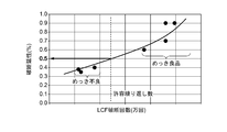
- the breaking ductility (once, not repeatedly) of the electroless plating film is not less than 0.5% strain. According to the configuration (4), if it has a fracture characteristic of a strain of 0.5% or more, a plating film having high fatigue fracture resistance can be formed, and an allowable number of repetitions can be satisfied in a low cycle fatigue test. Thereby, generation
- the impeller is a compressor impeller of a supercharger.
- the erosion resistance and crack resistance (fatigue strength) of the compressor impeller can be improved by using the impeller of the configuration as a compressor impeller of a supercharger that rotates at high speed. . Thereby, a long-life compressor impeller can be realized.
- a compressor according to at least one embodiment of the present invention includes: A compressor impeller formed by the impeller of any one of the configurations (1) to (5) is provided. According to the configuration (6), it is possible to extend the life of the compressor by providing the compressor impeller having high erosion resistance and crack resistance (fatigue strength).
- the supercharger according to at least one embodiment of the present invention is: A compressor having the configuration (6); A turbine for driving the compressor; It has. According to the configuration (7), by providing a compressor having a compressor impeller having high erosion resistance and crack resistance (fatigue strength), a long-life supercharger that can withstand high-speed rotation for a long time is realized. it can.
- the compressor in an intake passage of an internal combustion engine,
- the turbine is configured to be driven by exhaust from the internal combustion engine;
- a part of the exhaust gas is circulated in the intake passage upstream of the compressor.
- intake air including exhaust gas including droplets and high erosion property is introduced into a compressor of the supercharger.
- the turbocharger having the configuration (7) has the configuration (6), and has an improved erosion resistance and crack resistance (fatigue strength). Therefore, a long-life supercharger that can withstand high-speed rotation for a long period of time can be realized.
- a method of manufacturing an impeller for a rotary machine includes: A method of manufacturing an impeller for a rotary machine, Forming an electroless plating film as a surface layer of the impeller so as to cover a base of the impeller constituted by Al or an Al alloy,
- the electroless plating film is a Ni—P alloy having an amorphous structure and having a P content of 5 wt% or more and 11 wt% or less in the electroless plating film.
- the electroless plating film is formed on the surface. Since the electroless plating film has an amorphous structure, it has high strength and good erosion resistance. Moreover, since the P content of the electroless plating film is 5% by weight or more and 11% by weight or less, good crack resistance (fatigue strength) can be realized while having high Vickers hardness. Moreover, since the said electroless-plating film
- a test piece is further cut out from the impeller on which the electroless plating film is formed, and the test piece is further used to evaluate the fracture ductility of the electroless plating film.
- the hardness and ductility of the plating film vary depending on the plating process conditions, for example, the total area of the object to be plated with respect to the plating process liquid during the plating process, the flow rate of the plating process liquid and the relative speed of the object to be plated. According to the method (10), since the evaluation is performed using the test piece cut out from the impeller on which the electroless plating film is formed, the fracture ductility of the electroless plating film in the actual impeller can be accurately evaluated.
- the test piece is obtained from the rear surface of the hub by projecting the blade root portion of the hub of the impeller onto the rear surface side of the hub.
- the impeller generates stress due to centrifugal force generated by rotation, but as shown in FIG. 14, the blade root portion of the impeller is a place where the greatest stress is generated.
- the ductility of the test piece is grasped from the back side of the hub by collecting the region where the blade root portion of the hub is projected on the back side of the hub, thereby grasping the fracture ductility under the severest stress conditions. it can.
- the method further includes a step of changing a plating condition of the electroless plating film.
- the fracture ductility of the electroless plating film can be set to a threshold value or more by changing the plating condition of the plating film based on the result of the fracture ductility.
- the erosion resistance and crack resistance (fatigue strength) of the impeller can be improved at the same time, thereby extending the service life of the impeller and the equipment provided with the impeller. Is possible.
- an expression indicating that things such as “identical”, “equal”, and “homogeneous” are in an equal state not only represents an exactly equal state, but also has a tolerance or a difference that can provide the same function. It also represents the existing state.
- expressions representing shapes such as quadrangular shapes and cylindrical shapes represent not only geometrically strict shapes such as quadrangular shapes and cylindrical shapes, but also irregularities and chamfers as long as the same effects can be obtained. A shape including a part or the like is also expressed.
- the expressions “comprising”, “comprising”, “comprising”, “including”, or “having” one constituent element are not exclusive expressions for excluding the existence of other constituent elements.
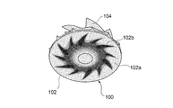
- FIG. 14 shows a compressor impeller of a supercharger provided in an internal combustion engine for a vehicle.
- a strain distribution generated in a compressor impeller 100 provided with a conventional Ni—P plating film is applied to the rear surface 102 a of the hub 102.
- the projected analysis results are shown. From FIG. 14, it can be seen that the greatest distortion, that is, stress is generated in the region 102 b in which the root portion of the blade 104 is projected in the bubb 102.
- This stress is mainly generated by the centrifugal force generated by the high-speed rotation of the turbocharger, and is generated by the difference in thermal elongation between the Ni—P-based plating film and the base material composed of an Al alloy or the like. Things are added.
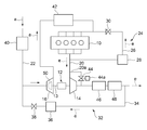
- the supercharger 12 is provided in a vehicular internal combustion engine, for example, a diesel engine 10 employing an EGR system.
- the supercharger 12 is provided in the exhaust passage 20 of the diesel engine 10, and includes an exhaust turbine 14 that is rotated by exhaust e, and a compressor 16 that is linked to the exhaust turbine 14 via a rotary shaft 13.
- the compressor 16 is provided in the intake passage 22 and supplies intake air a to the diesel engine 10. A part of the exhaust gas is circulated to the intake passage 22 upstream of the compressor 16.
- a high pressure EGR system 24 branches from an exhaust passage 20 upstream of the exhaust turbine 14 and is connected to an intake passage 22 upstream of the compressor 16.
- a part of the exhaust e discharged from the diesel engine 10 is returned to the intake passage 22 on the inlet side of the diesel engine 10 via the high pressure EGR passage 26.
- an EGR cooler 28 and an EGR valve 30 are provided in the high-pressure EGR path 26.
- the low pressure EGR system 32 has a low pressure EGR path 34 that branches from the exhaust path 20 downstream of the exhaust turbine 14 and is connected to an intake path 22 upstream of the compressor 16.
- a part of the exhaust e discharged from the diesel engine 10 is returned to the intake passage 22 on the inlet side of the compressor 16 via the low pressure EGR passage 34.
- an EGR cooler 36 and an EGR valve 38 are provided in the low pressure EGR path 34.
- an air cleaner 40 is provided in the intake passage 22 upstream of the compressor 16, and an intercooler 42 is provided in the intake passage 22 downstream of the compressor 16.
- an exhaust bypass path 20 a is connected to the exhaust path 20 so as to straddle the exhaust turbine 14.
- a waste valve 44 is provided in the exhaust bypass passage 20a, and an actuator 44a for adjusting the opening degree of the waste valve 44 is provided.
- the compressor is, for example, the compressor 16 provided in the supercharger 12 shown in FIG.
- the compressor 16 includes a compressor impeller 50 provided at one end of the rotary shaft 13 inside a compressor housing (not shown).
- the compressor impeller 50 has a configuration as shown in FIG. 13, for example.
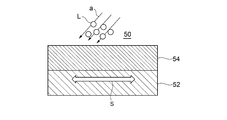
- the compressor impeller 50 has an electroless plating film 54 formed on the surface of a substrate 52 made of Al or an Al alloy.
- the electroless plating film 54 is made of a Ni—P alloy having an amorphous structure and having a P content of 5 wt% or more and 11 wt% or less.
- the electroless plating film 54 Since the electroless plating film 54 has an amorphous structure, the electroless plating film 54 has high strength and can exhibit high erosion resistance, and has a high Vickers hardness because the P content is 5 wt% or more and 11 wt% or less. Good crack resistance (fatigue strength) can be realized. This makes it possible to achieve both erosion resistance and crack resistance. Further, since the electroless plating film 54 is an electroless plating film, it is possible to form a uniform film such as a film thickness, and the two characteristics of the plating film can be exhibited uniformly over a wide range. As shown in FIG. 2, foreign matter such as droplets L may be mixed in the intake air a. For example, when the low-pressure EGR system 32 shown in FIG.
- the exhaust e containing water droplets L is circulated through the low-pressure EGR passage 34 and supplied to the compressor together with the intake air a.
- the electroless plating film 54 has good erosion resistance and crack resistance, and therefore erodes the exhaust e. It is difficult to prevent cracks from occurring.
- FIG. 3 is a test result showing the relationship between the P content of the electroless plating film 54 and the erosion resistance
- FIG. 4 is a fracture of the P content of the electroless plating film 54 and the low cycle fatigue (LCF) test. It is a test result which shows the relationship with a lifetime.
- Low cycle fatigue (LCF) refers to fatigue failure that occurs in a member when a large repetitive load that causes plastic deformation is applied to the member.
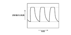
- FIG. 5 shows an example of a repetitive load applied to the compressor impeller in the LCF test. The horizontal axis represents time, and the vertical axis represents the rotational speed of the supercharger equipped with the compressor impeller. The repeated load applied to the electroless plating film 54 increases or decreases as the rotational speed of the supercharger increases or decreases.
- the P content is set to 5% by weight or more and 11% by weight or less from the viewpoint of achieving both erosion resistance and LCF fracture life.
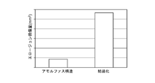
- FIG. 6 is a test result showing the relationship between the difference in the crystal structure of the electroless plating film 54 and the erosion resistance
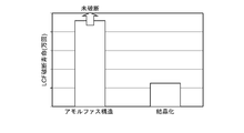
- FIG. 7 shows the relationship between the difference in the crystal structure of the electroless plating film 54 and the LCF fracture life. It is a test result shown. “Crystallation” in these figures indicates that the electroless plating film 54 having an amorphous structure is crystallized by heat treatment or the like. As shown in FIGS. 6 and 7, when the electroless plating film 54 is crystallized, the erosion resistance and the LCF rupture life are rapidly reduced. Based on these results, the electroless plating film 54 has an amorphous structure from the viewpoint of improving erosion resistance and LCF fracture life.
- the electroless plating film 54 has a film thickness of 15 ⁇ m or more and 60 ⁇ m or less. If the film thickness of the electroless plating film 54 is less than 15 ⁇ m, it may be difficult to sufficiently exhibit erosion resistance and crack resistance. On the other hand, even when the film thickness exceeds 60 ⁇ m, the effect of improving the erosion resistance and crack resistance is limited, and conversely, the time required for the plating treatment becomes longer and the cost is increased. Therefore, by setting the film thickness of the electroless plating film 54 to 15 ⁇ m or more, the erosion resistance and the crack resistance can be exhibited, and by setting the film thickness to 60 ⁇ m or less, the cost of the plating process can be reduced.
- FIG. 8 shows test results showing the relationship between the film thickness of the electroless plating film 54 and the erosion resistance.
- FIG. 9 shows test results showing the relationship between the corrosion resistance and film thickness of the electroless plating film 54.
- FIG. 8 when the film thickness of the electroless plating film 54 is about 1 to 2 ⁇ m, erosion resistance cannot be exhibited, and when the film thickness is 15 to 60 ⁇ m, high erosion resistance can be exhibited.
- Lines A, B, and C in FIG. 9 indicate the degree of progress of corrosion of the electroless plating film 54 when the corrosive environment is different.
- FIG. 9 shows that the required life can be satisfied even in the most severe corrosive environment when the film thickness of the electroless plating film 54 is 15 ⁇ m or more.
- the electroless plating film 54 has a Vickers hardness of 500 HV or more and 700 HV or less. In this case, since the electroless plating film 54 has a Vickers hardness of 500 HV or more, it can exhibit erosion resistance, and on the other hand, since it has a Vickers hardness of 700 HV or less, high crack resistance can be realized.
- the fracture life of the LCF fracture test clears the allowable number of repetitions. No cracks.
- the electroless plating film 54 having the above-described structure is a plating film having high fatigue fracture resistance, the generation of cracks in the impeller can be suppressed, and the life of the impeller can be extended.
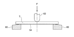
- the fracture ductility is measured, for example, by a test as shown in FIG. In FIG. 11, both ends of a flat test piece T having a rectangular cross section are placed on a support base 60 with the surface on which the electroless plating film 54 is formed facing downward.
- the indenter 62 is applied to the middle upper surface in the axial direction of the test piece T, and a load F is applied downward to cause a predetermined distortion. This operation is performed while changing the load until the plating film breaks.
- the compressor impeller 50 having the above-described configuration as a compressor impeller of the supercharger 12 that rotates at high speed, the erosion resistance of the compressor impeller 50 can be improved and the progress of cracks can be suppressed. It is possible to extend the life of the turbocharger 12 equipped with Further, even when the turbocharger 12 is provided in the diesel engine 10 having the low pressure EGR system 32 and the intake air a including the droplets and the exhaust having high erosion property is introduced into the compressor 16, the turbocharger 12 can withstand high-speed rotation for a long period of time. Can extend the service life.
- the manufacturing method of the impeller of the rotary machine is provided on the surface of the compressor impeller 50 so as to cover the compressor impeller 50 made of Al or Al alloy.
- a step (S14) of forming an electroless plating film 54 is provided.
- the electroless plating film 54 is an Ni—P alloy having an amorphous structure and having a P content in the electroless plating film 54 of 5 wt% or more and 11 wt% or less.
- the compressor impeller 50 manufactured by the above method has an electroless plating film 54 formed on the surface. Since the electroless plating film 54 has an amorphous structure, it has high strength and good erosion resistance. Moreover, since P content is 5 weight% or more and 11 weight% or less, it has favorable crack resistance (fatigue strength), having high Vickers hardness. In addition, since the electroless plating film 54 can form a uniform film such as a film thickness, high erosion resistance and crack resistance (fatigue strength) can be exhibited uniformly throughout the plating film.
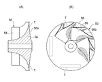
- Step S12 for evaluating the fracture ductility is further provided. That is, as shown in FIG. 13, the test piece T is cut out from the compressor impeller 50, and the fracture ductility is measured using the test piece T.
- the hardness and ductility of the plating film vary depending on the plating process conditions, for example, the total area of the object to be plated with respect to the plating process liquid during the plating process, the flow rate of the plating process liquid and the relative speed of the object to be plated. Since the fracture ductility is evaluated using the test piece T cut out from the compressor impeller 50 on which the electroless plating film 54 is formed, the fracture ductility of the electroless plating film 54 in the actually manufactured compressor impeller 50 is accurately determined. I can grasp.
- the test piece T takes a region 56 b obtained by projecting the blade root of the hub 56 of the compressor impeller 50 toward the back surface 56 a of the hub 56 from the back surface 56 a of the hub 56. .
- the compressor impeller 50 is stressed due to the centrifugal force generated by the rotation, but as shown in FIG. 14, the blade root portion of the hub 56 is a place where the greatest stress is generated.
- the plating conditions for example, the flow of the plating treatment liquid and the object to be plated are formed
- the electroless plating film 54 is formed.
- step S18 for changing the relative speed, plating time, etc.
- a pre-processing S10 of the test piece T cut out prior to step S12 is performed.
- the pretreatment S10 includes, for example, an alkaline degreasing step S10a that removes oils and fats adhering to the surface of the test piece T using an alkaline solution, and the surface of the test piece T after degreasing using an acid solution or an alkaline solution
- the plating film forming step S14 as an exemplary embodiment, first, Zn is plated on the surface of the test piece T, and then the Ni—P alloy is replaced with Zn to form the electroless plating film 54. .
- a step S20 for performing surface finishing of the test piece T and an inspection step S22 for inspecting the finished test piece T are performed.
- an electroless plating film that can achieve both good erosion resistance and good crack resistance (fatigue strength) can be formed on an impeller of a rotary machine, The service life of the impeller and the equipment including the impeller can be extended.
Landscapes
- Engineering & Computer Science (AREA)
- Chemical & Material Sciences (AREA)
- Mechanical Engineering (AREA)
- General Engineering & Computer Science (AREA)
- Materials Engineering (AREA)
- Combustion & Propulsion (AREA)
- General Chemical & Material Sciences (AREA)
- Chemical Kinetics & Catalysis (AREA)
- Metallurgy (AREA)
- Organic Chemistry (AREA)
- Structures Of Non-Positive Displacement Pumps (AREA)
- Chemically Coating (AREA)
- Supercharger (AREA)
Abstract
Description
また、過給機のコンプレッサ羽根車には、高速回転で発生する遠心力による応力と、Ni-P系めっき皮膜とAl合金との熱伸び差とによる応力とが発生する。そのため、めっき皮膜には耐エロージョン性だけでなく、耐き裂性(疲労強度)及び耐剥離性(堺面強度)が要求される。
一旦、めっき皮膜にき裂が発生すると、その後、該き裂は母材に進展し、母材の破損につながる。
このように、耐エロージョン性と耐き裂性とは両立しにくい関係にあり、これらの性質を両立させることは容易ではない。
回転機械の羽根車であって、
Al又はAl合金によって構成される前記羽根車の基材と、
前記基材を覆うように設けられて前記羽根車の表面層を形成する無電解めっき皮膜と、を備え、
前記無電解めっき皮膜は、アモルファス構造を有し、且つ、前記無電解めっき皮膜中におけるP含有率が5重量%以上11重量%以下であるNi-P系合金である。
また、前記無電解めっき皮膜は、膜厚など均一な皮膜形成が可能となるため、広範囲にわたってめっき皮膜の前記特性を均一に発揮できる。
前記無電解めっき皮膜は、15μm以上60μm以下の膜厚を有する。
前記無電解めっき皮膜の膜厚が15μm未満では、耐エロージョン性及び耐き裂性を十分に発揮することが難しい。他方、60μmを超える膜厚としても耐エロージョン性や耐き裂性の向上効果は限定的であるし、逆に、めっき処理に要する時間が長くなり、高コストとなる。
前記構成(9)によれば、前記無電解めっき皮膜の膜厚を15μm以上とすることで、耐エロージョン性及び耐き裂性を発揮でき、かつ60μm以下とすることで、めっき処理を低コスト化できる。
前記無電解めっき皮膜は、500HV以上700HV以下のビッカース硬さを有する。
前記構成(3)によれば、前記無電解めっき皮膜は、500HV以上のビッカース硬さを有するため、耐エロージョン性を発揮でき、他方、700HV以下のビッカース硬さであるため、優れた耐き裂性を実現できる。
前記無電解めっき皮膜の破断延性(繰り返しではなく1回)が歪み0.5%以上である。
前記構成(4)によれば、歪み0.5%以上の破断特性を有すれば、耐疲労破断性の高いめっき皮膜を形成でき、低サイクル疲労試験で許容繰返し数を満足することができる。これにより、羽根車のき裂の発生を抑制でき、羽根車を長寿命化できる。
前記羽根車は、過給機のコンプレッサ羽根車である。
前記構成(5)によれば、前記構成の羽根車を高速回転する過給機のコンプレッサ羽根車として用いることで、該コンプレッサ羽根車の耐エロージョン性及び耐き裂性(疲労強度)を向上できる。これによって、長寿命のコンプレッサ羽根車を実現できる。
前記構成(1)~(5)の何れかの羽根車によって形成されるコンプレッサ羽根車を有する。
前記構成(6)によれば、高い耐エロージョン性及び耐き裂性(疲労強度)を有するコンプレッサ羽根車を備えることで、コンプレッサの長寿命化が可能になる。
前記構成(6)のコンプレッサと、
前記コンプレッサを駆動するためのタービンと、
を備えている。
前記構成(7)によれば、高い耐エロージョン性及び耐き裂性(疲労強度)を有するコンプレッサ羽根車を有するコンプレッサを備えることで、高速回転に長期間耐え得る長寿命の過給機を実現できる。
前記コンプレッサは、内燃機関の吸気路に設けられ、
前記タービンは、前記内燃機関からの排気によって駆動されるように構成され、
前記コンプレッサの上流側において、前記排気の一部が前記吸気路に循環されるように構成される。
前記構成(8)のように、例えば、EGRシステムを採用した内燃機関に設けられる過給機では、過給機のコンプレッサに液滴を含みエロージョン性が高い排気を含む吸気が導入される。
これに対し、前記構成(8)によれば、前記構成(7)を有する過給機は、前記構成(6)を有し、耐エロージョン性及び耐き裂性(疲労強度)が向上したコンプレッサを備えているので、高速回転に長期間耐え得る長寿命な過給機を実現できる。
回転機械の羽根車の製造方法であって、
Al又はAl合金によって構成される前記羽根車の基材を覆うように、前記羽根車の表面層として無電解めっき皮膜を形成するステップを備え、
前記無電解めっき皮膜は、アモルファス構造を有し、且つ、前記無電解めっき皮膜中におけるP含有率が5重量%以上11重量%以下であるNi-P系合金である。
また、前記無電解めっき皮膜は、膜厚など均一な皮膜形成が可能となるため、広範囲にわたってめっき皮膜の前記特性を均一に発揮できる。
前記無電解めっき皮膜が形成された前記羽根車から試験片を切り出し、該試験片を用いて前記無電解めっき皮膜の破断延性を評価するステップをさらに備える。
めっき処理条件、例えば、めっき処理時におけるめっき処理液に対する被めっき処理物の総面積や、めっき処理液の流れと被めっき処理物との相対速度等によって、めっき皮膜の硬さや延性が変化する。
前記(10)の方法によれば、無電解めっき皮膜が形成された羽根車から切り出した試験片を使って評価するので、実物の羽根車における無電解めっき皮膜の破断延性を正確に評価できる。
前記試験片は前記羽根車のハブのブレード根元部を前記ハブの背面側に投影した領域を前記ハブの背面から採取する。
羽根車には、回転によって発生する遠心力などに起因した応力が発生するが、図14にも示すように、羽根車のブレード根元部は最も大きな応力が発生する場所である。
前記構成(11)によれば、試験片を前記ハブのブレード根元部を前記ハブの背面側に投影した領域をハブの背面側から採取することで、最も厳しい応力条件下での破断延性を把握できる。
前記破断延性が閾値を下回る場合、前記無電解めっき皮膜のめっき条件を変更するステップをさらに備える。
前記(12)の方法によれば、前記破断延性の結果に基き、前記めっき皮膜のめっき条件を変更することで、前記無電解めっき皮膜の破断延性を閾値以上とすることができる。
例えば、「ある方向に」、「ある方向に沿って」、「平行」、「直交」、「中心」、「同心」或いは「同軸」等の相対的或いは絶対的な配置を表す表現は、厳密にそのような配置を表すのみならず、公差、若しくは、同じ機能が得られる程度の角度や距離をもって相対的に変位している状態も表すものとする。
例えば、「同一」、「等しい」及び「均質」等の物事が等しい状態であることを表す表現は、厳密に等しい状態を表すのみならず、公差、若しくは、同じ機能が得られる程度の差が存在している状態も表すものとする。
例えば、四角形状や円筒形状等の形状を表す表現は、幾何学的に厳密な意味での四角形状や円筒形状等の形状を表すのみならず、同じ効果が得られる範囲で、凹凸部や面取り部等を含む形状も表すものとする。
一方、一つの構成要素を「備える」、「具える」、「具備する」、「含む」、又は「有する」という表現は、他の構成要素の存在を除外する排他的な表現ではない。
過給機12は、ディーゼルエンジン10の排気路20に設けられ、排気eによって回転する排気タービン14と、排気タービン14と回転軸13を介して連動するコンプレッサ16とを備えている。コンプレッサ16は吸気路22に設けられ、吸気aをディーゼルエンジン10に供給する。排気の一部はコンプレッサ16の上流側の吸気路22に循環される。
高圧EGRシステム24において、ディーゼルエンジン10から排出された排気eの一部は、高圧EGR路26を介してディーゼルエンジン10の入口側で吸気路22に戻される。
例示的な構成では、高圧EGR路26にEGRクーラ28及びEGRバルブ30が設けられる。
低圧EGRシステム32において、ディーゼルエンジン10から排出された排気eの一部は、低圧EGR路34を介してコンプレッサ16の入口側の吸気路22に戻される。
例示的な構成では、低圧EGR路34にEGRクーラ36及びEGRバルブ38が設けられる。
また、排気タービン14を跨ぐように、排気路20に排気バイパス路20aが接続されている。排気バイパス路20aにウェイストバルブ44が設けられ、ウェイストバルブ44の開度を調整するアクチュエータ44aが設けられる。
さらに、排気タービン14の下流側の排気路20に、排気中の粒子状物質を捕捉するDPFフィルタ48と、排気中のNOxをNO2に酸化し、NO2の酸化作用でDPFフィルタ48に捕捉された粒子状物質を燃焼させる酸化触媒46が設けられる。
コンプレッサ羽根車50は、図2に模式的に示すように、Al又はAl合金で構成される基材52の表面に、無電解めっき皮膜54が形成されている。無電解めっき皮膜54は、アモルファス構造を有し、かつ皮膜中におけるP含有率が5重量%以上11重量%以下のNi-P系合金で構成されている。
また、無電解めっき皮膜54は無電解めっき皮膜であるため、膜厚など均一な皮膜形成が可能となり、広範囲においてめっき皮膜の前記2つの特性を均一に発揮できる。
図2に示すように、吸気aには液滴Lなどの異物が混入している場合がある。例えば、図1に示す低圧EGRシステム32を採用する場合、水滴Lを含む排気eが低圧EGR路34を介して循環されて吸気aとともにコンプレッサに供給される。このように、吸気a中に異物(例えば、液滴L)が混ざっている場合においても、無電解めっき皮膜54は良好な耐エロージョン性及び耐き裂性を有するため、排気eに対して浸食されにくく、且つき裂の発生を抑制できる。
図5は、LCF試験においてコンプレッサ羽根車に加えられる繰り返し荷重の一例を示し、横軸は時間を、縦軸は該コンプレッサ羽根車を備えた過給機の回転数を示している。該過給機の回転数の増減により無電解めっき皮膜54に加えられる繰り返し荷重が増減する。
以上の結果を踏まえて、無電解めっき皮膜54では、耐エロージョン性及びLCF破断寿命を両立させる観点から、P含有率は5重量%以上11重量%以下としている。
図6及び図7に示すように、無電解めっき皮膜54が結晶化すると、耐エロージョン性及びLCF破断寿命が急激に低下する。
これらの結果を踏まえて、無電解めっき皮膜54は、耐エロージョン性及びLCF破断寿命を改善する観点から、アモルファス構造としている。
従って、無電解めっき皮膜54の膜厚を15μm以上とすることで、耐エロージョン性及び耐き裂性を発揮でき、かつ60μm以下とすることで、めっき処理を低コスト化できる。
図8に示すように、無電解めっき皮膜54の膜厚が1~2μm程度では耐エロージョン性を発揮できず、膜厚が15~60μmの範囲では高い耐エロージョン性を発揮できる。図9中のラインA、B及びCは、腐食環境が異なる場合の無電解めっき皮膜54の腐食の進行度を示している。図9から、無電解めっき皮膜54の膜厚が15μm以上のとき、最も厳しい腐食環境でも要求寿命を満足できることがわかる。
これによって、前記構成を有する無電解めっき皮膜54は、耐疲労破断の高いめっき皮膜であるため、羽根車のき裂の発生を抑制でき、羽根車を長寿命化できる。
破断延性は、例えば、図11に示すような試験によって測定する。図11において、断面長方形の平板状の試験片Tの両端を、無電解めっき皮膜54が形成された面を下方にして支持台60の上に載置する。次に、圧子62を試験片Tの軸方向真ん中上面に当て下方へ荷重Fを付加し、所定の歪みを生じさせる。この操作をめっき皮膜が破断するまで荷重を変えて行う。
また、過給機12が低圧EGRシステム32を備えたディーゼルエンジン10に設けられ、コンプレッサ16に液滴を含みエロージョン性が高い排気を含む吸気aが導入される場合でも、高速回転に長期間耐えることができ、長寿命化できる。
無電解めっき皮膜54は、アモルファス構造を有し、且つ、無電解めっき皮膜54中におけるP含有率が5重量%以上11重量%以下であるNi-P系合金である。
また、無電解めっき皮膜54は、膜厚など均一な皮膜形成が可能となるため、めっき皮膜全域で高い耐エロージョン性及び耐き裂性(疲労強度)を均一に発揮できる。
即ち、図13に示すように、コンプレッサ羽根車50から試験片Tを切り出し、試験片Tを用いて破断延性を測定する。
めっき処理条件、例えば、めっき処理時におけるめっき処理液に対する被めっき処理物の総面積や、めっき処理液の流れと被めっき処理物との相対速度等によって、めっき皮膜の硬さや延性が変化する。
無電解めっき皮膜54が形成されたコンプレッサ羽根車50から切り出した試験片Tを使って破断延性を評価するので、実際に製造されたコンプレッサ羽根車50における無電解めっき皮膜54の破断延性を正確に把握できる。
コンプレッサ羽根車50には、回転によって発生する遠心力などに起因した応力が発生するが、図14にも示すように、ハブ56のブレード根元部は最も大きな応力が発生する場所である。
試験片Tを前記領域56bから採取することで、最も厳しい応力条件下での破断延性を把握できる。
これによって、破断延性の結果に基き、無電解めっき皮膜54のめっき条件を変更することで、無電解めっき皮膜54の破断延性を閾値以上とすることができる。
前処理S10は、例えば、試験片Tの表面に付着した油脂類をアルカリ液などを使って除去するアルカリ脱脂ステップS10aと、脱脂後の試験片Tに対し、酸液又はアルカリ液を用いて表面に形成された不動態膜(アルミナ膜)を除去するエッチング処理S10bと、エッチング処理後、酸などに溶解しにくいCやSiが黒い微粉末状となって残るスマットを除去するスマット除去ステップS10cとを行う。
例示的な実施形態では、めっき膜厚形成ステップS14の後、試験片Tの表面仕上げを行うステップS20及び仕上げ後の試験片Tを検査する検査ステップS22を行う。
12 過給機
13 回転軸
14 排気タービン
16 コンプレッサ
20 排気路
22 吸気路
24 高圧EGRシステム
26 高圧EGR路
28、36 EGRクーラ
30、38 EGRバルブ
32 低圧EGRシステム
34 低圧EGR路
40 エアクリーナ
42 インタクーラ
44 ウェイストバルブ
44a アクチュエータ
46 酸化触媒
48 DPFフィルタ
50、100 コンプレッサ羽根車
52 基材
54 無電解めっき皮膜
56、102 ハブ
56a、102a 背面
58、104 ブレード
60 支持台
62 圧子
C き裂
S 歪み
a 吸気
e 排気
Claims (12)
- 回転機械の羽根車であって、
Al又はAl合金によって構成される前記羽根車の基材と、
前記基材を覆うように設けられて前記羽根車の表面層を形成する無電解めっき皮膜と、を備え、
前記無電解めっき皮膜は、アモルファス構造を有し、且つ、前記無電解めっき皮膜中におけるP含有率が5重量%以上11重量%以下であるNi-P系合金であることを特徴とする回転機械の羽根車。 - 前記無電解めっき皮膜は、15μm以上60μm以下の膜厚を有することを特徴とする請求項1に記載の回転機械の羽根車。
- 前記無電解めっき皮膜は、500HV以上700HV以下のビッカース硬さを有することを特徴とする請求項1又は2に記載の回転機械の羽根車。
- 前記無電解めっき皮膜の破断延性は歪み0.5%以上であることを特徴とする請求項1乃至3の何れか1項に記載の回転機械の羽根車。
- 前記羽根車は、過給機のコンプレッサ羽根車であることを特徴とする請求項1乃至4の何れか1項に記載の回転機械の羽根車。
- 請求項1乃至5の何れか1項に記載の羽根車によって形成されるコンプレッサ羽根車を有するコンプレッサ。
- 請求項6に記載のコンプレッサと、
前記コンプレッサを駆動するためのタービンと、
を備えることを特徴とする過給機。 - 前記コンプレッサは、内燃機関の吸気路に設けられ、
前記タービンは、前記内燃機関からの排気によって駆動されるように構成され、
前記コンプレッサの上流側において、前記排気の一部が前記吸気路に循環されるように構成されたことを特徴とする請求項7に記載の過給機。 - 回転機械の羽根車の製造方法であって、
Al又はAl合金によって構成される前記羽根車の基材を覆うように、前記羽根車の表面層として無電解めっき皮膜を形成するステップを備え、
前記無電解めっき皮膜は、アモルファス構造を有し、且つ、前記無電解めっき皮膜中におけるP含有率が5重量%以上11重量%以下であるNi-P系合金であることを特徴とする回転機械の羽根車の製造方法。 - 前記無電解めっき皮膜が形成された前記羽根車から試験片を切り出し、該試験片を用いて前記無電解めっき皮膜の破断延性を評価するステップをさらに備えることを特徴とする請求項9に記載の回転機械の羽根車の製造方法。
- 前記試験片は、前記羽根車のハブのブレード根元部を前記ハブの背面側に投影した領域を前記ハブの背面から採取することを特徴とする請求項10に記載の回転機械の羽根車の製造方法。
- 前記破断延性が閾値を下回る場合、前記無電解めっき皮膜のめっき条件を変更するステップをさらに備えることを特徴とする請求項10又は11に記載の回転機械の羽根車の製造方法。
Priority Applications (6)
| Application Number | Priority Date | Filing Date | Title |
|---|---|---|---|
| US15/546,453 US20180045215A1 (en) | 2015-03-25 | 2015-03-25 | Impeller for rotary machine, compressor, supercharger, and method for producing impeller for rotary machine |
| CN202111253581.6A CN114060101A (zh) | 2015-03-25 | 2015-03-25 | 旋转机械的叶轮、压缩机、增压器以及旋转机械的叶轮的制造方法 |
| EP15886346.4A EP3276143B1 (en) | 2015-03-25 | 2015-03-25 | Impeller for rotary machine, compressor, supercharger, and method for manufacturing impeller for rotary machine |
| CN201580075410.5A CN107208545A (zh) | 2015-03-25 | 2015-03-25 | 旋转机械的叶轮、压缩机、增压器以及旋转机械的叶轮的制造方法 |
| JP2017507241A JP6386162B2 (ja) | 2015-03-25 | 2015-03-25 | 回転機械の羽根車、コンプレッサ、過給機及び回転機械の羽根車の製造方法 |
| PCT/JP2015/059092 WO2016151793A1 (ja) | 2015-03-25 | 2015-03-25 | 回転機械の羽根車、コンプレッサ、過給機及び回転機械の羽根車の製造方法 |
Applications Claiming Priority (1)
| Application Number | Priority Date | Filing Date | Title |
|---|---|---|---|
| PCT/JP2015/059092 WO2016151793A1 (ja) | 2015-03-25 | 2015-03-25 | 回転機械の羽根車、コンプレッサ、過給機及び回転機械の羽根車の製造方法 |
Publications (1)
| Publication Number | Publication Date |
|---|---|
| WO2016151793A1 true WO2016151793A1 (ja) | 2016-09-29 |
Family
ID=56977433
Family Applications (1)
| Application Number | Title | Priority Date | Filing Date |
|---|---|---|---|
| PCT/JP2015/059092 Ceased WO2016151793A1 (ja) | 2015-03-25 | 2015-03-25 | 回転機械の羽根車、コンプレッサ、過給機及び回転機械の羽根車の製造方法 |
Country Status (5)
| Country | Link |
|---|---|
| US (1) | US20180045215A1 (ja) |
| EP (1) | EP3276143B1 (ja) |
| JP (1) | JP6386162B2 (ja) |
| CN (2) | CN107208545A (ja) |
| WO (1) | WO2016151793A1 (ja) |
Cited By (5)
| Publication number | Priority date | Publication date | Assignee | Title |
|---|---|---|---|---|
| JP2018080652A (ja) * | 2016-11-17 | 2018-05-24 | 株式会社名光精機 | インペラ及びその製造方法 |
| WO2018147169A1 (ja) * | 2017-02-10 | 2018-08-16 | 三菱重工業株式会社 | 耐環境性部材、並びに、これを用いた羽根車、圧縮機及びエンジン |
| JP2019039434A (ja) * | 2018-11-19 | 2019-03-14 | 三菱重工業株式会社 | 積層部材、並びに、これを用いた羽根車、圧縮機及びエンジン |
| JP2019039435A (ja) * | 2018-11-19 | 2019-03-14 | 三菱重工業株式会社 | 積層部材、並びに、これを用いた羽根車、圧縮機及びエンジン |
| WO2019130405A1 (ja) | 2017-12-25 | 2019-07-04 | 三菱重工エンジン&ターボチャージャ株式会社 | コンプレッサホイールおよび過給機 |
Families Citing this family (3)
| Publication number | Priority date | Publication date | Assignee | Title |
|---|---|---|---|---|
| JP6593732B2 (ja) * | 2016-06-01 | 2019-10-23 | 三菱重工エンジン&ターボチャージャ株式会社 | 回転機械用羽根車、コンプレッサ、過給機、及び回転機械用羽根車の製造方法 |
| US11566631B2 (en) * | 2021-03-29 | 2023-01-31 | Garrett Transportation I Inc. | Turbocharger compressor wheels having a bi-layered coating and methods for manufacturing the same |
| US12404867B2 (en) | 2023-03-10 | 2025-09-02 | Garrett Transportation I Inc. | Wheels having a bi-layered coating including a hard coating layer and methods for making the same |
Citations (3)
| Publication number | Priority date | Publication date | Assignee | Title |
|---|---|---|---|---|
| JPH06322557A (ja) * | 1993-05-06 | 1994-11-22 | Mitsubishi Electric Corp | 耐食性摺接部材およびその製造方法 |
| JP2009270152A (ja) * | 2008-05-07 | 2009-11-19 | Nakayama Steel Works Ltd | 高耐食性アモルファス合金 |
| JP2014163345A (ja) * | 2013-02-27 | 2014-09-08 | Mitsubishi Heavy Ind Ltd | 舶用ディーゼル機関の排気再循環システム |
Family Cites Families (11)
| Publication number | Priority date | Publication date | Assignee | Title |
|---|---|---|---|---|
| CN2427647Y (zh) * | 2000-03-06 | 2001-04-25 | 岳勇 | 高耐腐蚀高耐磨耗的防砂抽油泵 |
| JP2004176082A (ja) * | 2002-11-25 | 2004-06-24 | Osaka Gas Co Ltd | 高耐食性部材及びその製造方法 |
| JP2007197766A (ja) * | 2006-01-26 | 2007-08-09 | Mitsubishi Heavy Ind Ltd | 防食コーティングを施した回転機械 |
| JP2007245567A (ja) * | 2006-03-16 | 2007-09-27 | Fujifilm Corp | 機能性膜含有構造体及びその製造方法 |
| JP4709731B2 (ja) * | 2006-11-17 | 2011-06-22 | 三菱重工業株式会社 | 耐食性めっき層形成方法および回転機械 |
| JP2010202900A (ja) * | 2009-03-02 | 2010-09-16 | Alps Electric Co Ltd | 電気接点の製造方法 |
| JP5406569B2 (ja) * | 2009-03-12 | 2014-02-05 | 株式会社クレハ | ポリグリコール酸系樹脂組成物およびその成形体 |
| US20110027576A1 (en) * | 2009-07-28 | 2011-02-03 | General Electric Company | Sealing of pinholes in electroless metal coatings |
| US20110206532A1 (en) * | 2010-02-23 | 2011-08-25 | General Electric Company | Electroless metal coatings |
| CN102321887B (zh) * | 2011-10-18 | 2013-06-05 | 上海西工压缩机配件有限公司 | 经复合表面改性的38CrMoAl压缩机叶片及其制备工艺 |
| ITCO20120015A1 (it) * | 2012-04-12 | 2013-10-13 | Nuovo Pignone Srl | Metodo per la prevenzione della corrosione e componente ottenuto mediante tale metodo |
-
2015
- 2015-03-25 WO PCT/JP2015/059092 patent/WO2016151793A1/ja not_active Ceased
- 2015-03-25 EP EP15886346.4A patent/EP3276143B1/en active Active
- 2015-03-25 CN CN201580075410.5A patent/CN107208545A/zh active Pending
- 2015-03-25 JP JP2017507241A patent/JP6386162B2/ja active Active
- 2015-03-25 US US15/546,453 patent/US20180045215A1/en not_active Abandoned
- 2015-03-25 CN CN202111253581.6A patent/CN114060101A/zh active Pending
Patent Citations (3)
| Publication number | Priority date | Publication date | Assignee | Title |
|---|---|---|---|---|
| JPH06322557A (ja) * | 1993-05-06 | 1994-11-22 | Mitsubishi Electric Corp | 耐食性摺接部材およびその製造方法 |
| JP2009270152A (ja) * | 2008-05-07 | 2009-11-19 | Nakayama Steel Works Ltd | 高耐食性アモルファス合金 |
| JP2014163345A (ja) * | 2013-02-27 | 2014-09-08 | Mitsubishi Heavy Ind Ltd | 舶用ディーゼル機関の排気再循環システム |
Cited By (9)
| Publication number | Priority date | Publication date | Assignee | Title |
|---|---|---|---|---|
| JP2018080652A (ja) * | 2016-11-17 | 2018-05-24 | 株式会社名光精機 | インペラ及びその製造方法 |
| WO2018147169A1 (ja) * | 2017-02-10 | 2018-08-16 | 三菱重工業株式会社 | 耐環境性部材、並びに、これを用いた羽根車、圧縮機及びエンジン |
| CN110225998A (zh) * | 2017-02-10 | 2019-09-10 | 三菱重工业株式会社 | 耐环境性构件和使用该耐环境性构件的叶轮、压缩机以及发动机 |
| CN110225998B (zh) * | 2017-02-10 | 2023-08-11 | 三菱重工业株式会社 | 叶轮、压缩机以及发动机 |
| WO2019130405A1 (ja) | 2017-12-25 | 2019-07-04 | 三菱重工エンジン&ターボチャージャ株式会社 | コンプレッサホイールおよび過給機 |
| US11300140B2 (en) | 2017-12-25 | 2022-04-12 | Mitsubishi Heavy Industries Engine & Turbocharger, Ltd. | Compressor wheel and supercharger |
| EP3712401B1 (en) * | 2017-12-25 | 2024-08-14 | Mitsubishi Heavy Industries Engine & Turbocharger, Ltd. | Compressor wheel and supercharger |
| JP2019039434A (ja) * | 2018-11-19 | 2019-03-14 | 三菱重工業株式会社 | 積層部材、並びに、これを用いた羽根車、圧縮機及びエンジン |
| JP2019039435A (ja) * | 2018-11-19 | 2019-03-14 | 三菱重工業株式会社 | 積層部材、並びに、これを用いた羽根車、圧縮機及びエンジン |
Also Published As
| Publication number | Publication date |
|---|---|
| CN114060101A (zh) | 2022-02-18 |
| EP3276143A1 (en) | 2018-01-31 |
| JPWO2016151793A1 (ja) | 2017-08-03 |
| EP3276143B1 (en) | 2019-02-06 |
| EP3276143A4 (en) | 2018-04-25 |
| CN107208545A (zh) | 2017-09-26 |
| US20180045215A1 (en) | 2018-02-15 |
| JP6386162B2 (ja) | 2018-09-05 |
Similar Documents
| Publication | Publication Date | Title |
|---|---|---|
| JP6386162B2 (ja) | 回転機械の羽根車、コンプレッサ、過給機及び回転機械の羽根車の製造方法 | |
| JP6295008B2 (ja) | 回転機械の羽根車、コンプレッサ、過給機及び回転機械の羽根車の製造方法 | |
| EP1995412A2 (en) | Sheath for use on airfoil components | |
| EP4067668B1 (en) | Turbocharger compressor wheels having a bi-layered coating and methods for manufacutring the same | |
| JP2008111425A (ja) | ガスタービンエンジン圧縮機用摩擦皮膜 | |
| WO2006126993A1 (en) | Turbocharger compressor having improved erosion-corrosion resistance | |
| US20070140853A1 (en) | Dovetail surface enhancement for durability | |
| CN109312660B (zh) | 旋转机械用叶轮、压缩机、增压器及旋转机械用叶轮的制造方法 | |
| JP2014163345A (ja) | 舶用ディーゼル機関の排気再循環システム | |
| US10266958B2 (en) | Hot corrosion-protected articles and manufacture methods | |
| JP6486978B2 (ja) | 積層部材、並びに、これを用いた羽根車、圧縮機及びエンジン | |
| US11225876B2 (en) | Diffusion barrier to prevent super alloy depletion into nickel-CBN blade tip coating | |
| US20130011270A1 (en) | Coatings for gas turbine components | |
| EP3839095A1 (en) | Barrier to prevent super alloy depletion into nickel-cbn blade tip coating | |
| US20250163814A1 (en) | Wheels having a bi-layered coating and methods for making the same | |
| US20130323066A1 (en) | Maskant for fluoride ion cleaning | |
| JP6625959B2 (ja) | インペラ及びその製造方法 | |
| EP3090075B1 (en) | Hot corrosion-protected article and manufacture method therefor |
Legal Events
| Date | Code | Title | Description |
|---|---|---|---|
| 121 | Ep: the epo has been informed by wipo that ep was designated in this application |
Ref document number: 15886346 Country of ref document: EP Kind code of ref document: A1 |
|
| ENP | Entry into the national phase |
Ref document number: 2017507241 Country of ref document: JP Kind code of ref document: A |
|
| WWE | Wipo information: entry into national phase |
Ref document number: 15546453 Country of ref document: US |
|
| REEP | Request for entry into the european phase |
Ref document number: 2015886346 Country of ref document: EP |
|
| NENP | Non-entry into the national phase |
Ref country code: DE |