WO2016151897A1 - 弁開閉時期制御装置 - Google Patents
弁開閉時期制御装置 Download PDFInfo
- Publication number
- WO2016151897A1 WO2016151897A1 PCT/JP2015/077089 JP2015077089W WO2016151897A1 WO 2016151897 A1 WO2016151897 A1 WO 2016151897A1 JP 2015077089 W JP2015077089 W JP 2015077089W WO 2016151897 A1 WO2016151897 A1 WO 2016151897A1
- Authority
- WO
- WIPO (PCT)
- Prior art keywords
- current
- phase
- state
- drive current
- drive
- Prior art date
- Legal status (The legal status is an assumption and is not a legal conclusion. Google has not performed a legal analysis and makes no representation as to the accuracy of the status listed.)
- Ceased
Links
Images


Classifications
-
- F—MECHANICAL ENGINEERING; LIGHTING; HEATING; WEAPONS; BLASTING
- F01—MACHINES OR ENGINES IN GENERAL; ENGINE PLANTS IN GENERAL; STEAM ENGINES
- F01L—CYCLICALLY OPERATING VALVES FOR MACHINES OR ENGINES
- F01L1/00—Valve-gear or valve arrangements, e.g. lift-valve gear
- F01L1/34—Valve-gear or valve arrangements, e.g. lift-valve gear characterised by the provision of means for changing the timing of the valves without changing the duration of opening and without affecting the magnitude of the valve lift
- F01L1/344—Valve-gear or valve arrangements, e.g. lift-valve gear characterised by the provision of means for changing the timing of the valves without changing the duration of opening and without affecting the magnitude of the valve lift changing the angular relationship between crankshaft and camshaft, e.g. using helicoidal gear
- F01L1/356—Valve-gear or valve arrangements, e.g. lift-valve gear characterised by the provision of means for changing the timing of the valves without changing the duration of opening and without affecting the magnitude of the valve lift changing the angular relationship between crankshaft and camshaft, e.g. using helicoidal gear making the angular relationship oscillate, e.g. non-homokinetic drive
-
- F—MECHANICAL ENGINEERING; LIGHTING; HEATING; WEAPONS; BLASTING
- F01—MACHINES OR ENGINES IN GENERAL; ENGINE PLANTS IN GENERAL; STEAM ENGINES
- F01L—CYCLICALLY OPERATING VALVES FOR MACHINES OR ENGINES
- F01L1/00—Valve-gear or valve arrangements, e.g. lift-valve gear
- F01L1/34—Valve-gear or valve arrangements, e.g. lift-valve gear characterised by the provision of means for changing the timing of the valves without changing the duration of opening and without affecting the magnitude of the valve lift
- F01L1/344—Valve-gear or valve arrangements, e.g. lift-valve gear characterised by the provision of means for changing the timing of the valves without changing the duration of opening and without affecting the magnitude of the valve lift changing the angular relationship between crankshaft and camshaft, e.g. using helicoidal gear
- F01L1/3442—Valve-gear or valve arrangements, e.g. lift-valve gear characterised by the provision of means for changing the timing of the valves without changing the duration of opening and without affecting the magnitude of the valve lift changing the angular relationship between crankshaft and camshaft, e.g. using helicoidal gear using hydraulic chambers with variable volume to transmit the rotating force
-
- F—MECHANICAL ENGINEERING; LIGHTING; HEATING; WEAPONS; BLASTING
- F16—ENGINEERING ELEMENTS AND UNITS; GENERAL MEASURES FOR PRODUCING AND MAINTAINING EFFECTIVE FUNCTIONING OF MACHINES OR INSTALLATIONS; THERMAL INSULATION IN GENERAL
- F16K—VALVES; TAPS; COCKS; ACTUATING-FLOATS; DEVICES FOR VENTING OR AERATING
- F16K31/00—Actuating devices; Operating means; Releasing devices
- F16K31/02—Actuating devices; Operating means; Releasing devices electric; magnetic
- F16K31/06—Actuating devices; Operating means; Releasing devices electric; magnetic using a magnet, e.g. diaphragm valves, cutting off by means of a liquid
- F16K31/10—Actuating devices; Operating means; Releasing devices electric; magnetic using a magnet, e.g. diaphragm valves, cutting off by means of a liquid with additional mechanism between armature and closure member
- F16K31/105—Actuating devices; Operating means; Releasing devices electric; magnetic using a magnet, e.g. diaphragm valves, cutting off by means of a liquid with additional mechanism between armature and closure member for rotating valves
-
- F—MECHANICAL ENGINEERING; LIGHTING; HEATING; WEAPONS; BLASTING
- F01—MACHINES OR ENGINES IN GENERAL; ENGINE PLANTS IN GENERAL; STEAM ENGINES
- F01L—CYCLICALLY OPERATING VALVES FOR MACHINES OR ENGINES
- F01L1/00—Valve-gear or valve arrangements, e.g. lift-valve gear
- F01L1/34—Valve-gear or valve arrangements, e.g. lift-valve gear characterised by the provision of means for changing the timing of the valves without changing the duration of opening and without affecting the magnitude of the valve lift
- F01L1/344—Valve-gear or valve arrangements, e.g. lift-valve gear characterised by the provision of means for changing the timing of the valves without changing the duration of opening and without affecting the magnitude of the valve lift changing the angular relationship between crankshaft and camshaft, e.g. using helicoidal gear
- F01L1/3442—Valve-gear or valve arrangements, e.g. lift-valve gear characterised by the provision of means for changing the timing of the valves without changing the duration of opening and without affecting the magnitude of the valve lift changing the angular relationship between crankshaft and camshaft, e.g. using helicoidal gear using hydraulic chambers with variable volume to transmit the rotating force
- F01L2001/34423—Details relating to the hydraulic feeding circuit
- F01L2001/34426—Oil control valves
- F01L2001/3443—Solenoid driven oil control valves
-
- F—MECHANICAL ENGINEERING; LIGHTING; HEATING; WEAPONS; BLASTING
- F01—MACHINES OR ENGINES IN GENERAL; ENGINE PLANTS IN GENERAL; STEAM ENGINES
- F01L—CYCLICALLY OPERATING VALVES FOR MACHINES OR ENGINES
- F01L2800/00—Methods of operation using a variable valve timing mechanism
-
- F—MECHANICAL ENGINEERING; LIGHTING; HEATING; WEAPONS; BLASTING
- F01—MACHINES OR ENGINES IN GENERAL; ENGINE PLANTS IN GENERAL; STEAM ENGINES
- F01L—CYCLICALLY OPERATING VALVES FOR MACHINES OR ENGINES
- F01L2800/00—Methods of operation using a variable valve timing mechanism
- F01L2800/01—Starting
-
- F—MECHANICAL ENGINEERING; LIGHTING; HEATING; WEAPONS; BLASTING
- F01—MACHINES OR ENGINES IN GENERAL; ENGINE PLANTS IN GENERAL; STEAM ENGINES
- F01L—CYCLICALLY OPERATING VALVES FOR MACHINES OR ENGINES
- F01L2800/00—Methods of operation using a variable valve timing mechanism
- F01L2800/09—Calibrating
Definitions
- the present invention relates to a valve opening / closing timing control device that controls a relative rotation phase of a driven side rotating body with respect to a driving side rotating body that rotates in synchronization with a crankshaft of an internal combustion engine.
- valve opening / closing timing control device that can change the opening / closing timings of an intake valve and an exhaust valve in accordance with the operating state of an internal combustion engine (hereinafter also referred to as “engine”) has been put into practical use.
- This valve opening / closing timing control device changes the relative rotation phase of the driven-side rotator relative to the rotation of the drive-side rotator by the operation of the engine (hereinafter also simply referred to as “relative rotation phase”), thereby rotating the driven-side rotation. It has a mechanism that changes the opening and closing timing of the intake and exhaust valves that are opened and closed as the body rotates.
- the optimal opening / closing timing of the intake / exhaust valve varies depending on the engine operating conditions such as when the engine is started and when the vehicle is running.
- the relative rotation phase is constrained to a predetermined phase between the most retarded angle phase and the most advanced angle phase, so that the intake / exhaust valve opening / closing timing optimum for engine start is achieved and the drive side rotation
- the partition portion of the fluid pressure chamber formed by the body and the driven-side rotating body is prevented from swinging and generating sound. For this reason, it is desirable that the relative rotational phase is constrained to a predetermined phase before the engine is stopped.
- Patent Document 1 discloses a valve opening / closing timing control device capable of locking a relative rotation phase to an intermediate lock phase based on an engine stop signal.
- advance control, retard control, intermediate phase holding control, and lock control at an intermediate lock phase are performed with one hydraulic control valve (electromagnetic valve). These controls are performed by changing the position of the spool of the hydraulic control valve according to the drive current (power supply amount) applied to the electromagnetic solenoid.
- drive current power supply amount
- FIG. 21 of Patent Document 1 shows that when the drive current is changed from 0 to the maximum, “locking to the intermediate lock phase by retarding operation”, “retarding operation in the unlocked state”, “ A case where control is performed so as to switch between five states of “intermediate phase holding”, “advance angle operation in unlocked state”, and “lock to intermediate lock phase by advance angle operation” is disclosed.
- a general valve opening / closing timing control device has two solenoid valves: a solenoid valve that performs phase control such as advance angle control, retard angle control, and intermediate phase retention; and a solenoid valve that performs lock control such as locking and unlocking at an intermediate lock phase. It has a solenoid valve. Therefore, each solenoid valve is controlled to switch between three states or two states. Therefore, it is easy to assign the movable range of the spool in each solenoid valve to the position of each phase control or lock control, and the controllability is enhanced by widening the range of drive current that can maintain one state. be able to. Further, since the phase control and the lock control are performed by independent solenoid valves, for example, when the phase is displaced in the unlocked state, the lock state is not erroneously switched.
- the valve opening / closing timing control device disclosed in Patent Document 1 since the above four or five states are controlled by a single hydraulic control valve, spools that can maintain the respective states are controlled. The control position and the range of drive current are narrowed. For this reason, in each state, the control range of the drive current is expanded to the vicinity of the boundary between adjacent states so as to improve the controllability as much as possible.
- the upper limit value and the lower limit value of the drive current that is, the value of the drive current that can maintain the state in the vicinity of the boundary between adjacent states (hereinafter referred to as the boundary current) is: Normally, it is set only when the vehicle is manufactured, and is not changed thereafter. In addition, the boundary current may change due to reasons such as changes in the external environment and deterioration of the hydraulic control valve itself.
- the characteristic configuration of the valve opening / closing timing control device includes a drive-side rotator that rotates synchronously with a drive shaft of an internal combustion engine, and the drive-side rotator inside the drive-side rotator.
- a driven-side rotating body that is disposed coaxially with the axial center of the internal combustion engine and rotates integrally with a valve opening / closing cam shaft of the internal combustion engine, and a most advanced angle phase in a relative rotational phase of the driven-side rotating body with respect to the driving-side rotating body
- An intermediate lock mechanism that selectively switches between a locked state in which the displacement of the relative rotational phase is restrained by hydraulic fluid supplied at an intermediate lock phase that is between the most retarded angle phase and the unlocked state in which the locked state is released And the position of the spool is changed by changing the drive current applied to the drive source, and the hydraulic oil is selectively supplied or discharged according to the position of the spool.
- an electromagnetic valve that selectively switches between supply and discharge of hydraulic oil to the intermediate lock mechanism and is displaced in an advance angle direction or a retard angle direction, and during the predetermined operation of the internal combustion engine, the drive current is The value of the drive current that is different from the value of the drive current at the time of switching from the unlocked state to the locked state by changing, and that maintains the unlocked state becomes a boundary current. In that it is configured to be set.
- the driving current is changed to be different from a driving current value when the driving current is changed to switch from the unlocked state to the locked state, and
- the value of the drive current that maintains the unlocked state is set as the boundary current.
- an advance displacement in which the relative rotation phase is displaced in the advance direction across the intermediate lock phase, and a retard direction in which the relative rotation phase is over the intermediate lock phase It is preferable that the drive current is changed so that the retarded displacement that is displaced in the direction alternately occurs.
- valve opening / closing timing control device when at least one of the advance angle displacement and the retard angle displacement occurs a plurality of times, the value of the drive current when the actuator is displaced twice in the same direction. Is preferably set so that the value of the driving current after the value of the driving current is closer to the value for switching to the locked state.
- valve opening / closing timing control device when switching to the locked state at any one of the advance angle displacement and the retard angle displacement, when subsequently displacing in the direction switched to the lock state
- the value of the applied drive current is preferably the boundary current.
- the drive current is changed so that the advance displacement and the retard displacement are alternately generated even when the boundary current of either the advance displacement or the retard displacement is set first.
- the other boundary current by displacing the relative rotational phase.
- the predetermined operation time is a start time of the internal combustion engine.
- the boundary current can be set when the internal combustion engine is started, so the drive current that can maintain the unlocked state in the vicinity of the drive current that always switches to the locked state is set as the boundary current. can do. As a result, switching of a plurality of states in the electromagnetic valve can be reliably controlled.
- the predetermined operation time is a time of switching to the locked state in spite of application of the driving current for maintaining the unlocked state.
- valve opening / closing timing control device when switching to the locked state unlike the driver's intention, the valve opening / closing timing control device can be operated according to the driver's intention by newly setting the boundary current. it can.
- the drive that maintains the unlocked state during the predetermined operation than the predetermined value when the predetermined operation is when the internal combustion engine is started It is preferable that the predetermined value in the case of switching to the locked state despite the application of current is larger.
- the predetermined value can be increased so that it will never switch back to the locked state.
- FIG. 2 is a cross-sectional view taken along the line II-II in FIG.
- valve open / close timing control device 10 according to an embodiment of the present invention mounted on an engine E as an internal combustion engine will be described in detail with reference to the drawings.
- a valve opening / closing timing control device 10 shown in FIG. 1 includes a housing 1 that rotates synchronously with a crankshaft C, and a camshaft for opening and closing a valve of an engine E that is disposed coaxially with an axis X of the housing 1 inside the housing 1. 101 and an internal rotor 2 that rotates integrally.
- the camshaft 101 is a rotating shaft of the cam 104 that controls the opening and closing of the intake valve 103 of the engine E.
- the crankshaft C is an example of a drive shaft
- the housing 1 is an example of a drive side rotator
- the internal rotor 2 is an example of a driven side rotator.
- the housing 1 and the internal rotor 2 are combined, and the fixing bolt 5 is inserted through the center, and the male screw of the fixing bolt 5 and the female screw of the camshaft 101 are screwed together. Thereby, the fixing bolt 5 is fixed to the camshaft 101 and the internal rotor 2 is also fixed to the camshaft 101.
- the housing 1 is configured by assembling a front plate 11, an external rotor 12 externally mounted on the internal rotor 2, and a rear plate 13 including a timing sprocket 15 with fastening bolts 16.
- the inner rotor 2 and the outer rotor 12 are configured to be rotatable relative to each other about the axis X.
- a return spring 70 for applying an urging force in the rotation direction about the axis X.
- the return spring 70 is a biasing force until the relative rotational phase of the internal rotor 2 with respect to the housing 1 (hereinafter also simply referred to as “relative rotational phase”) reaches a predetermined relative rotational phase on the advance side from the most retarded state. And the biasing force does not act in a region where the relative rotational phase is on the advance side of the predetermined rotational phase.
- the crankshaft C When the crankshaft C is rotationally driven, the rotational driving force is transmitted to the timing sprocket 15 via the power transmission member 102, and the housing 1 is rotationally driven in the rotational direction S shown in FIG.
- the housing 1 As the housing 1 is driven to rotate, the internal rotor 2 is driven to rotate in the rotational direction S, the camshaft 101 rotates, and the cam 104 pushes down the intake valve 103 of the engine E to open it.
- the outer rotor 12 is formed with three projecting portions 14 projecting radially inward and contacting the outer peripheral surface of the inner rotor 2 so as to be separated from each other along the rotational direction S.
- a fluid pressure chamber 4 is formed between the rotor 2 and the external rotor 12.
- the fluid pressure chamber 4 is divided into an advance chamber 41 and a retard chamber 42 by a protruding portion 21 formed in a portion facing the fluid pressure chamber 4 in the outer peripheral surface of the internal rotor 2.
- the hydraulic oil is supplied to and discharged from the advance chamber 41 and the retard chamber 42, or the supply and discharge of the hydraulic oil are shut off, so that the hydraulic pressure of the hydraulic oil is applied to the projecting portion 21, and the relative rotational phase is advanced in the advance direction S1. Alternatively, it is displaced in the retarding direction S2 or is held at an arbitrary phase.
- the relative rotational phase when the protruding portion 21 reaches the moving end in the advance direction S1 is referred to as the most advanced angle phase
- the relative rotational phase when the protruding portion 21 reaches the moving end in the retard direction S2 is the maximum. This is called a retarded phase.
- the absolute value of the relative rotation phase and the displacement direction of the relative rotation phase are detected by a crank angle sensor and a cam angle sensor (not shown) and input to an ECU (electronic control unit) (not shown).
- the internal rotor 2 is supplied to and discharged from an advance passage 43 communicating with the advance chamber 41, a retard passage 44 communicating with the retard chamber 42, and an intermediate lock mechanism 8 described later.
- An unlock passage 45 through which the working oil flows and a lock discharge passage 46 through which the working oil discharged from the intermediate lock mechanism 8 to the outside of the valve timing control device 10 flows are formed.
- the valve timing control device 10 includes an intermediate lock mechanism 8 that restricts the relative rotation phase to an intermediate lock phase P between the most advanced angle phase and the most retarded angle phase.
- the intermediate lock mechanism 8 includes a first lock member 81, a first spring 82, a second lock member 83, a second spring 84, a first recess 85, and a second recess 86. Composed.
- the first lock member 81 and the second lock member 83 are plate-shaped members, and are movable with respect to the external rotor 12 so as to be able to approach and separate toward the inner rotor 2 in a posture parallel to the axis X. It is supported.
- the first recess 85 is formed in a groove shape along the direction of the axis X on the outer periphery of the inner rotor 2
- the second recess 86 is a groove along the direction of the axis X on the outer periphery of the inner rotor 2. It is partitioned into a shape.
- the unlocking channel 45 is connected to the bottom surface of each of the deep groove of the first recess 85 and the deep groove of the second recess 86, and hydraulic fluid flows through the unlocking channel 45 when in the locked state.
- the first lock member 81 and the second lock member 83 receive the hydraulic pressure of the hydraulic oil.
- this hydraulic pressure exceeds the urging force of the first spring 82 and the second spring 84, the first lock member 81 and the second lock member 83 are separated from the first concave portion 85 and the second concave portion 86, respectively, and become unlocked.
- the lock discharge channel 46 is also connected to the bottom surfaces of the deep groove of the first recess 85 and the deep groove of the second recess 86, but the lock discharge channel 46 is supplied to the first recess 85 and the second recess 86.
- the hydraulic fluid is not allowed to flow, and only the hydraulic fluid discharged from the first recess 85 and the second recess 86 to the outside of the valve opening / closing timing control device 10 is allowed to flow.
- an OCV (oil control valve) 51 is disposed inside the inner rotor 2 and coaxially with the axis X.
- the OCV 51 is an example of a solenoid valve.
- the OCV 51 includes a spool 52, a coil spring 53 that biases the spool 52, and an electromagnetic solenoid 54 that drives the spool 52.
- the electromagnetic solenoid 54 is an example of a drive source. Moreover, since the structure of the electromagnetic solenoid 54 is well-known, detailed description is abbreviate
- the spool 52 is accommodated in the accommodating space 5a which is a hole having a circular cross section formed in the fixing bolt 5, and slides along the direction of the axis X.
- the spool 52 has a main discharge channel 52a which is a bottomed hole having a circular cross section along the direction of the axis X.
- the coil spring 53 is disposed in the inner part of the accommodation space 5a, and always urges the spool 52 in the direction of the electromagnetic solenoid 54 (left direction in FIG. 1).
- the spool 52 does not jump out of the storage space 5a by the stopper 55 attached to the storage space 5a.
- a step formed in the main discharge channel 52 a holds one of the coil springs 53.
- a partition 5d is inserted at the boundary between the accommodation space 5a and a bottomed hole having a small inner diameter formed continuously from the housing space 5a, and the partition 5d holds the other of the coil springs 53.
- the OCV 51 is configured to adjust the position of the spool 52 by changing the current applied to the electromagnetic solenoid 54 from 0 to the maximum.
- the value of the current applied to the electromagnetic solenoid 54 is controlled by the ECU.
- the OCV 51 switches the supply, discharge, and holding of the hydraulic oil to the advance chamber 41 and the retard chamber 42 according to the position of the spool 52, and switches the supply and discharge of the hydraulic oil to the intermediate lock mechanism 8.
- the hydraulic oil stored in the oil pan 61 is pumped up by a mechanical oil pump 62 that is driven by transmission of the rotational driving force of the crankshaft C, and circulates through the supply flow path 47. To do.
- the hydraulic oil that has flowed through the supply flow path 47 is supplied to the advance flow path 43, the retard flow path 44, and the lock release flow path 45 via the OCV 51.
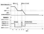
- FIG. 3 shows the operation configuration of the OCV 51 when the position of the spool 52 changes from W1 to W5 according to the current applied to the electromagnetic solenoid.
- the valve opening / closing timing control device 10 applies a drive current to the electromagnetic solenoid 54 to move the spool 52 of the OCV 51 along the axis X and stop it at a desired position.
- “locking to the intermediate locking phase by retarding operation (W1)”, “retarding operation in the unlocked state (W2)”, “intermediate phase holding (W3)”, “advance in the unlocked state” It is configured to be switched to five states, “angular operation (W4)” and “lock to intermediate lock phase by advance operation (W5)”.
- the OCV 51 is configured to be switchable between four states W1 to W4.
- the timing for resetting the boundary current includes, for example, when the engine E is started (hereinafter simply referred to as starting).
- starting the reason for the change in the external environment and the deterioration of the OCV 51 itself despite the application of the boundary current to the electromagnetic solenoid 54 that has been able to maintain the retarded angle operating state and the advanced angle operating state in the unlocked state until then.
- the value of the boundary current has been changed due to the change to the locked state (hereinafter referred to as “when unexpected lock occurs”).
- resetting is not limited to these two cases.
- the boundary current may be reset in any case such as when the battery is replaced or when the vehicle is inspected.
- start time and the unexpected lock occurrence are examples of “a predetermined operation of the internal combustion engine”.
- FIG. 4 shows an overall flowchart of the boundary current resetting procedure at the time of starting and unexpected lock occurrence.
- the control shown in the flowchart in the present application is performed by the ECU.
- the reset end flag of the retard side boundary current I ret is set to 0 before resetting at the time of starting, and the flag is set to 1 when resetting is completed.
- the reset end flag of the advance side boundary current I adv is set to 0 before resetting, and the flag is set to 1 when resetting is completed.
- the retard lock flag is 0 when the drive current I is applied to the electromagnetic solenoid 54 and the retard operation state is maintained, and the switch to the retard lock state has been made. Sometimes the retard lock flag is 1. Similarly, when the drive current I is applied to the electromagnetic solenoid 54 and the advance angle operating state is maintained, the advance angle lock flag is 0, and when the advance angle lock state is switched, the advance angle lock flag is 1.
- the relative rotation phase is locked at the intermediate lock phase P by the intermediate lock mechanism 8.
- the electromagnetic solenoid 54 is not energized yet, so that the locked state is continuously maintained. Thereafter, the electromagnetic solenoid 54 is energized to switch to the unlocked state (S402), and the values of the initial boundary current on the retard side and the advance side are set (S403).
- the value of the initial boundary current is a value that can ensure that the relative rotation phase is in the retarded angle operating state or the advanced angle operating state, and may be, for example, the value of the boundary current that has been set and operated normally.
- the resetting is not performed until the unexpected lock occurs (No in S407). If the unexpected lock occurs (Yes in S407), the unexpected lock boundary current reset subroutine (S408) is performed.
- FIG. 5 shows a flowchart of the procedure for resetting the retarded boundary current I ret at the start
- FIG. 7 shows a time chart of the actual relative rotation phase ⁇ and the drive current I in the reset procedure.
- initial currents in the retarded operating state and the advanced operating state are set by the ECU (S403), and the retarded side boundary current resetting subroutine (S404). ) Is started.
- the retard side boundary current resetting subroutine first, it is confirmed whether or not the reset of the retard side boundary current I ret has been completed with the retard side boundary current reset end flag, and the flag is 0. If there is (Yes in S501 in FIG. 5), the initial current to enter the retarded operation state is applied to the electromagnetic solenoid 54 as the drive current I (S502). If the locked state is not switched by the application of the initial current (No in S503), the actual relative rotation phase ⁇ is displaced from the intermediate lock phase P in the retarding direction S2 and becomes the W2 state as in the state C of FIG.
- the retard side boundary current I ret the value obtained by subtracting the value of the drive current I when applied to the electromagnetic solenoid 54 next time from the initial current by the retard side current change amount ⁇ (second period) Current) (S505).
- the retard side current change amount ⁇ is, for example, 5 mA.
- the second-phase current is more easily switched to the locked state than the initial current.
- the retard lock flag remains 0 (S506), and the reset end flag for the retard side boundary current I ret also remains 0, and the subroutine (S404) is terminated.
- the advance side boundary current resetting subroutine (S405 in FIG. 4) is executed. A detailed description of this subroutine will be given later. Regardless of the execution result of this subroutine, the resetting of the retard side boundary current I ret has not been completed. Therefore, the resetting is not completed (No in S406), and after the advance side boundary current resetting subroutine is executed. The retard side boundary current reset subroutine (S404) is executed again.
- the second phase current is applied to the electromagnetic solenoid 54 as the drive current I (S502), and if it still does not switch to the locked state (No in S503), FIG.
- the actual relative rotational phase ⁇ is displaced from the intermediate lock phase P in the retarding direction S2 to be in the W2 state.
- the ECU does not switch to the locked state in the second phase current, and re-establishes the retard side boundary current I ret . It is determined that the setting is incomplete. A value obtained by further reducing the value of the drive current I by the retarded-side current change amount ⁇ from the second-phase current when applied to the electromagnetic solenoid 54 for the third time in order to reset the retarded-side boundary current I ret. As (third phase current) (S505), the retard side boundary current resetting subroutine is terminated.
- the third phase current is applied as the drive current I to the electromagnetic solenoid 54 (S502).
- the lock state is switched (Yes in S503), so that the actual relative rotation phase ⁇ is constrained by the intermediate lock phase P and becomes the W1 state as in the G state of FIG. Thereby, it turned out that the electric current of the boundary which W2 and W1 switch exists between a 2nd period electric current and a 3rd period electric current.
- switching to the locked state is because the actual relative rotational phase ⁇ was not displaced to the retard side from the retard side folding threshold a for a predetermined time after applying the third phase current to the electromagnetic solenoid 54. It is determined (see FIG. 7).
- the second-phase current which is the drive current I immediately before switching from the unlocked state to the locked state, may be used as the boundary current.
- the retard lock flag is set to 1 (S509) and the reset end flag of the retard side boundary current I ret is set. Is also set to 1 (S510), and the subroutine (S404) is terminated.
- the sum of the retard side current change amount ⁇ and the retard side current margin ⁇ m is an example of a predetermined value.
- the retarding side boundary current resetting subroutine is continued until the advancement side boundary current resetting subroutine is completed. Need to run. In this case, since the reset end flag of the retard side boundary current I ret is already 1 (No in S501), the retard side boundary current I ret is applied as the drive current I (S511 in FIG. 5 and FIG. 7). I state, K state).
- FIG. 6 shows a flowchart of a procedure for resetting the advance side boundary current I adv at the start
- FIG. 7 shows a time chart of the actual relative rotational phase ⁇ and the drive current I in the reset procedure.
- the leading side boundary current is A reset subroutine is executed.
- this subroutine first, it is confirmed whether or not the resetting of the advance side boundary current I adv has been completed with the advance side boundary current resetting completion flag, and if the flag is 0 (see FIG. 6). (Yes in S601), the initial current that is already set to advance is applied to the electromagnetic solenoid 54 as the drive current I (S602, state D in FIG. 7). As a result, the actual relative rotational phase ⁇ is displaced toward the advance side. If the lock state is not switched by application of the initial current (No in S603), the actual relative rotation phase ⁇ exceeds the intermediate lock phase P and reaches the advance side, and enters the W4 state.
- the process returns to the beginning of the subroutine and the above flow is repeated. Since the actual relative rotational phase ⁇ is displaced to the advance side with respect to the advance side folding threshold value b during the repetition, if the state is reached (Yes in S604), the ECU has not switched to the locked state with the initial current. That is, it is determined that the advance side boundary current I adv has not been reset.
- the value of the drive current I when applied to the electromagnetic solenoid 54 next time to reset the advance side boundary current I adv is a value obtained by adding the advance side current change amount ⁇ to the initial current (second phase current).
- the advance angle side current change amount ⁇ is, for example, 5 mA.
- the second-phase current is more easily switched to the locked state than the initial current.
- the advance angle lock flag remains 0 (S606)
- the advance side boundary current I adv reset end flag remains 0 (S607)
- the subroutine (S405) is terminated.
- the retard side boundary current resetting subroutine described above is executed. Regardless of the execution result of this subroutine, resetting of the advance side boundary current I adv is incomplete, so resetting is not completed (No in S406), and after the retard side boundary current resetting subroutine is executed. The advance side boundary current reset subroutine is executed again.
- the second phase current is applied to the electromagnetic solenoid 54 as the drive current I (S602), and if it still does not switch to the locked state (No in S603), FIG.
- the actual relative rotation phase ⁇ is displaced from the intermediate lock phase P in the advance direction S1, and becomes the W4 state.
- the ECU does not switch to the locked state in the second phase current, and the advance side boundary current I adv is restored . It is determined that the setting is incomplete. A value obtained by adding the value of the drive current I when applied to the electromagnetic solenoid 54 for the third time in order to reset the advance side boundary current I adv to the second phase current by the advance side current change amount ⁇ . As (third phase current) (S605), the advance side boundary current resetting subroutine is terminated.
- the retard side boundary current resetting subroutine and the advance side boundary current resetting subroutine are executed alternately.
- the electromagnetic solenoid 54 has a drive current I as the fourth period current obtained by adding only the advance side current change amount ⁇ to the third period current. Even if it applied to, it did not switch to the locked state. As shown in the L state of FIG.
- the fourth current which is the drive current I immediately before switching from the unlocked state to the locked state, may be set as the boundary current.
- the advance angle lock flag is set to 1 (S609), and the reset end flag of the advance angle side boundary current I adv is set. Is also set to 1 (S610), and the advance side boundary current resetting subroutine is terminated.
- the sum of the advance angle side current change amount ⁇ and the advance angle side current margin ⁇ m is an example of a predetermined value.
- the retard side boundary current reset subroutine is also completed. ing. Since the resetting of both the retarded side and the advanced side boundary currents has been completed, the resetting flow is temporarily terminated (Yes in S406 in FIG. 4). After completion of the resetting flow, as shown by the M state in FIG. 7, the actual relative rotational phase ⁇ is displaced to the intermediate lock phase P in the unlocked state, and this state is maintained.
- the re-setting flow is repeated until the engine E is stopped by turning off the ignition switch (No in S409). However, unless the engine E is started (No in S401), the boundary current is not reset until the unexpected lock occurs (No in S407).
- the lock is performed in the vicinity of switching to the locked state as much as possible.
- the drive current I that can maintain the release state can be set as the boundary current. As a result, switching of the five states can be reliably performed.
- the reset side boundary current I ret is reset and the advance side boundary current I adv is reset in parallel. It is possible to reduce the time until the resetting is completed as compared with the case where each resetting is performed independently.
- the drive current I is changed so as to approach the lock state by a predetermined amount (the retard side current change amount ⁇ and the advance side current change amount ⁇ ) from the initial current in the unlocked state.
- FIG. 4 shows a flowchart of a procedure for resetting the retarded boundary current I ret when unexpected lock occurs
- FIG. 9 shows a time chart of the actual relative rotational phase ⁇ and the drive current I in the reset procedure.
- the actual relative rotational phase ⁇ is on the more advanced side than the intermediate lock phase P, and the phase is held so as not to be displaced (W3 state).
- the drive current I hereinafter referred to as the original retard angle side boundary current
- W2 the retard angle operating state
- the ECU determines that the OCV 51 is not in the retarded angle operating state (W2) but in the retarded angle locked state (W1). This is because the retard side boundary current I ret has changed to the increasing side due to a change in the external environment, deterioration of the OCV 51 itself, etc., so the value of the original retard side boundary current becomes the control range of the retard lock state. It is thought that it has been.
- the value of the original retard side boundary current is reset to a new value of the retard side boundary current I ret so as to surely enter the retarded operating state by the procedure as shown in FIG.
- the ECU is initially on the advanced angle side with respect to the intermediate lock phase P, and when trying to displace to the retard angle side, the retard side It is determined that the locked state is reached at the intermediate lock phase P without being able to reach.
- FIG. 9 shows the latter case.
- the first locking member 81 of the intermediate locking mechanism 8 is advanced to the first recess 85 since it is switched to the locked state. It is pressed against the side wall. Therefore, even if the drive current I that maintains the phase (W3) is applied to the electromagnetic solenoid 54, the first lock member 81 can be moved to the advance side only by supplying hydraulic fluid from the lock release passage 45. There is a concern that the first recess 85 may not be smoothly removed due to the frictional force between the wall surface.
- the first lock member 81 when a drive current I that causes the advance angle operation state (W4) is applied to the electromagnetic solenoid 54, the first lock member 81 is separated from the advance side wall surface of the first recess 85. 1 The lock member 81 can be removed (S803, state D in FIG. 9).
- the advance side boundary current I adv is also measured in the advance direction S1 in the same manner. Even if the relative rotational phase ⁇ is being displaced, even if it switches to an unintentional locked state, the advance side boundary current I adv should be reset quickly to reach the target relative rotational phase ⁇ smoothly. Can do.
- the present invention can be used for a valve opening / closing timing control device that controls a relative rotation phase of a driven side rotating body with respect to a driving side rotating body that rotates in synchronization with a crankshaft of an internal combustion engine.
Landscapes
- Engineering & Computer Science (AREA)
- General Engineering & Computer Science (AREA)
- Mechanical Engineering (AREA)
- Valve Device For Special Equipments (AREA)
- Magnetically Actuated Valves (AREA)
Abstract
弁開閉時期制御装置は、駆動側回転体と、従動側回転体と、駆動側回転体に対する従動側回転体の相対回転位相における中間ロック位相で相対回転位相の変位を拘束するロック状態と該ロック状態が解除されたロック解除状態とを選択的に切り替える中間ロック機構と、駆動源へ印加する駆動電流を変化させて相対回転位相を進角方向又は遅角方向に変位させると共に中間ロック機構にロック状態とロック解除状態とを切り替えさせる電磁弁とを備える。内燃機関の所定の作動時において、弁開閉時期制御装置は、駆動電流を変化させてロック解除状態からロック状態に切り替わったときの駆動電流の値に対して、所定の値だけ異なり、且つ、ロック解除状態に切り替わる駆動電流の値を境界電流に設定する。
Description
本発明は、内燃機関のクランクシャフトと同期して回転する駆動側回転体に対する従動側回転体の相対回転位相を制御する弁開閉時期制御装置に関する。
近年、内燃機関(以下「エンジン」とも称する)の運転状況に応じて吸気弁及び排気弁の開閉時期を変更可能とする弁開閉時期制御装置が実用化されている。この弁開閉時期制御装置は、例えば、エンジンの作動による駆動側回転体の回転に対する従動側回転体の相対回転位相(以下、単に「相対回転位相」とも称する)を変化させることにより、従動側回転体の回転に伴って開閉される吸排気弁の開閉時期を変更する機構を有している。
一般に、吸排気弁の最適な開閉時期はエンジンの始動時や車両の走行時などエンジンの運転状況により異なる。エンジンの始動時には、相対回転位相を最遅角位相と最進角位相との間の所定位相に拘束することにより、エンジンの始動に最適な吸排気弁の開閉時期を実現すると共に、駆動側回転体と従動側回転体によって形成される流体圧室の仕切部が揺動して打音が発生するのを抑制している。そのため、エンジンを停止させる前には、相対回転位相を所定位相に拘束しておくことが望まれる。
特許文献1には、エンジンの停止信号に基づいて相対回転位相を中間ロック位相にロックさせることができる弁開閉時期制御装置が開示されている。この弁開閉時期制御装置においては、1個の油圧制御弁(電磁弁)で進角制御、遅角制御、中間位相保持制御、中間ロック位相でのロック制御を行う。これらの制御は、油圧制御弁のスプールの位置を電磁ソレノイドへ印加する駆動電流(給電量)に応じて変化させることにより行われる。具体的には、特許文献1の図6には、駆動電流を0から最大まで変化させたときに、(1)「全ドレン」、「進角作動による中間ロック位相へのロック」、「ロック解除した状態での進角作動」、「中間位相保持」、「ロック解除した状態での遅角作動」の4つの状態を切り替えるよう制御される場合と、(2)「ロック解除した状態での遅角作動」、「中間位相保持」、「ロック解除した状態での進角作動」、「進角作動による中間ロック位相へのロック」、「全ドレン」の4つの状態を切り替えるよう制御される場合とが開示されている。
また、特許文献1の図21には、駆動電流を0から最大まで変化させたときに、「遅角作動による中間ロック位相へのロック」、「ロック解除した状態での遅角作動」、「中間位相保持」、「ロック解除した状態での進角作動」、「進角作動による中間ロック位相へのロック」の5つの状態を切り替えるよう制御される場合が開示されている。
一般的な弁開閉時期制御装置は、進角制御、遅角制御、中間位相保持という位相制御を行う電磁弁と、中間ロック位相でのロック、ロック解除というロック制御を行う電磁弁の2個の電磁弁を備えている。そのため、各々の電磁弁では3つの状態、又は、2つの状態を切り替える制御がなされる。よって、それぞれの電磁弁におけるスプールの可動範囲を各位相制御又はロック制御の位置に振り分けることは容易であると共に、1つの状態を維持することができる駆動電流の範囲を広くして制御性を高めることができる。また、位相制御とロック制御とは独立した電磁弁で行われるので、例えばロック解除の状態で位相を変位させているときに、誤ってロック状態に切り替わることはない。
一方、特許文献1に開示された弁開閉時期制御装置では、1個の油圧制御弁で上記の4つ又は5つの状態を切り替える制御が行われるので、それぞれの状態を維持することができるスプールの制御位置、及び、駆動電流の範囲が狭くなる。そのため、各状態においては、隣接する状態の境界近傍まで駆動電流の制御範囲を広げて、少しでも制御性を高めるようにしている。一方、各状態における、駆動電流の上限値と下限値、すなわち、隣接する状態との境界近傍で、且つ、当該状態を維持することができる駆動電流の値(以下、境界電流と称する)は、通常は車両製造時にのみ設定され、その後は変更されない。また、境界電流は、外部環境の変化や油圧制御弁自体の劣化等の理由により変化する場合がある。
油圧制御弁の構造上、「遅角作動による中間ロック位相へのロック」と「ロック解除した状態での遅角作動」は互いに隣接する状態である。また、「進角作動による中間ロック位相へのロック」と「ロック解除した状態での進角作動」も互いに隣接する状態である。そのため、隣接する状態の境界近傍まで駆動電流の制御範囲を広げた場合、上記の理由により「ロック解除した状態での遅角作動」の境界電流や「ロック解除した状態での進角作動」の境界電流が変化すると、車両製造時に設定した「ロック解除した状態での遅角作動」や「ロック解除した状態での進角作動」の境界電流の値を電磁ソレノイドに印加しているにもかかわらず「遅角作動による中間ロック位相へのロック」や「進角作動による中間ロック位相へのロック」の状態に切り替わるおそれがあった。この場合、進角作動や遅角作動の途中で中間ロック位相にロックされてしまう。このように、4つ又は5つの状態を切り替える制御が行われる油圧制御弁を弁開閉時期制御装置に用いる場合には、境界電流の設定に関して更なる改良の余地があった。
このように、エンジンの作動中に境界電流の再設定が可能な弁開閉時期制御装置が求められている。
上記課題を解決するために、本発明に係る弁開閉時期制御装置の特徴構成は、内燃機関の駆動軸と同期回転する駆動側回転体と、前記駆動側回転体の内側で前記駆動側回転体の軸心と同軸心に配置され、前記内燃機関の弁開閉用のカムシャフトと一体回転する従動側回転体と、前記駆動側回転体に対する前記従動側回転体の相対回転位相における最進角位相と最遅角位相の間にある中間ロック位相で供給される作動油によって前記相対回転位相の変位を拘束するロック状態と該ロック状態が解除されたロック解除状態とを選択的に切り替える中間ロック機構と、駆動源へ印加される駆動電流が変化することによってスプールの位置が変更され、前記スプールの位置に応じて作動油が選択的に供給又は排出されることにより、前記相対回転位相が進角方向又は遅角方向に変位すると共に前記中間ロック機構への作動油の供給と排出とを選択的に切り替える電磁弁とを備え、前記内燃機関の所定の作動時において、前記駆動電流が変化することによって前記ロック解除状態から前記ロック状態に切り替わったときの前記駆動電流の値に対して、所定の値だけ異なり、且つ、前記ロック解除状態を維持する前記駆動電流の値が境界電流に設定されるように構成される点にある。
このような特徴構成とすれば、内燃機関の所定の作動時において、駆動電流を変化させてロック解除状態からロック状態に切り替わったときの駆動電流の値に対して、所定の値だけ異なり、且つ、ロック解除状態を維持する駆動電流の値を境界電流に設定する。これにより、例えば、外部環境の変化や電磁弁の劣化等の理由によりロック解除状態からロック状態に切り替わる駆動電流(境界電流)に変化が生じていた場合でも、できるだけロック状態に切り替わる駆動電流の近傍で、ロック解除状態を維持することができる駆動電流を新たな境界電流に設定することができる。その結果、電磁弁における複数の状態の切り替えの制御を確実に行うことができる。
本発明に係る弁開閉時期制御装置においては、前記相対回転位相が前記中間ロック位相を跨いで進角方向へ変位する進角変位と、前記相対回転位相が前記中間ロック位相を跨いで遅角方向へ変位する遅角変位とが交互に発生するように前記駆動電流を変化させると好適である。
このような構成とすれば、進角変位と遅角変位とが交互に発生するように駆動電流を変化させて相対回転位相を変位させることにより、遅角側の境界電流の設定と進角側の境界電流の設定とを並行して行うことができ、各々を独立して設定する場合と比較して、設定を完了するまでの時間を短縮することができる。
本発明に係る弁開閉時期制御装置においては、前記進角変位と前記遅角変位との少なくとも一方が複数回発生する場合に、連続する2回の同方向へ変位するときの前記駆動電流の値は、先の前記駆動電流の値よりも後の前記駆動電流の値の方が前記ロック状態に切り替わる値に近くなるように設定されると好適である。
このような構成とすれば、駆動電流を繰り返し印加するたびにロック状態に切り替わる値に近づくので、ロック解除状態での遅角作動と進角作動を行うことができる駆動電流の範囲を広げることができ、電磁弁の制御性を高めることができる。
本発明に係る弁開閉時期制御装置においては、前記進角変位と前記遅角変位のいずれかのときに前記ロック状態に切り替わった場合は、その後に前記ロック状態に切り替わった方向に変位するときに印加される前記駆動電流の値は前記境界電流であると好適である。
このような構成とすれば、進角変位と遅角変位のいずれか一方の境界電流が先に設定された場合でも、進角変位と遅角変位とが交互に発生するように駆動電流を変化させて相対回転位相を変位させて、いずれか他方の境界電流を設定することができる。
本発明に係る弁開閉時期制御装置においては、前記所定の作動時とは、前記内燃機関の始動時であると好適である。
このような構成とすれば、内燃機関の始動時に境界電流を設定することができるので、常にロック状態に切り替わる駆動電流の近傍で、ロック解除状態を維持することができる駆動電流を境界電流に設定することができる。その結果、電磁弁における複数の状態の切り替えの制御を確実に行うことができる。
本発明に係る弁開閉時期制御装置においては、前記所定の作動時とは、前記ロック解除状態を維持する前記駆動電流を印加したにも関わらず前記ロック状態に切り替わった時であると好適である。
このような構成とすれば、運転者の意思とは異なってロック状態に切り替わった場合、境界電流を新たに設定することにより、運転者の意思に沿って弁開閉時期制御装置を作動させることができる。
本発明に係る弁開閉時期制御装置においては、前記所定の作動時が前記内燃機関の始動時である場合の前記所定の値よりも、前記所定の作動時が前記ロック解除状態を維持する前記駆動電流を印加したにも関わらず前記ロック状態に切り替わった時である場合の前記所定の値の方が大きいと好適である。
運転者の意思とは異なってロック状態に切り替わる方が運転中には危険度が高いため、所定の値を大きくして、二度と意に反してロック状態に切り替わらないようにすることができる。
1.弁開閉時期制御装置の構成
以下に、内燃機関としてのエンジンEに搭載された本発明の実施形態に係る弁開閉時期制御装置10について、図面に基づいて詳細に説明する。
以下に、内燃機関としてのエンジンEに搭載された本発明の実施形態に係る弁開閉時期制御装置10について、図面に基づいて詳細に説明する。
〔全体構成〕
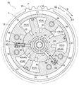
図1に示す弁開閉時期制御装置10は、クランクシャフトCと同期回転するハウジング1と、ハウジング1の内側でハウジング1の軸心Xと同軸心に配置され、エンジンEの弁開閉用のカムシャフト101と一体回転する内部ロータ2とを備えている。カムシャフト101は、エンジンEの吸気弁103の開閉を制御するカム104の回転軸である。なお、クランクシャフトCは駆動軸の一例であり、ハウジング1は駆動側回転体の一例であり、内部ロータ2は従動側回転体の一例である。
図1に示す弁開閉時期制御装置10は、クランクシャフトCと同期回転するハウジング1と、ハウジング1の内側でハウジング1の軸心Xと同軸心に配置され、エンジンEの弁開閉用のカムシャフト101と一体回転する内部ロータ2とを備えている。カムシャフト101は、エンジンEの吸気弁103の開閉を制御するカム104の回転軸である。なお、クランクシャフトCは駆動軸の一例であり、ハウジング1は駆動側回転体の一例であり、内部ロータ2は従動側回転体の一例である。
ハウジング1と内部ロータ2を組み合わせた状態で固定ボルト5を中心に挿通し、固定ボルト5の雄ねじとカムシャフト101の雌ねじとを螺着する。これにより、固定ボルト5がカムシャフト101に対して固定されると共に、内部ロータ2もカムシャフト101に対して固定される。
ハウジング1は、フロントプレート11と、内部ロータ2に外装される外部ロータ12と、タイミングスプロケット15を備えるリヤプレート13とを締結ボルト16により組み付けて構成される。内部ロータ2と外部ロータ12とは、軸心Xを中心にして相対回転自在に構成されている。
ハウジング1とカムシャフト101との間には、軸心Xを中心とする回転方向に付勢力を作用させる戻しばね70を備えている。この戻しばね70は、ハウジング1に対する内部ロータ2の相対回転位相(以下、単に「相対回転位相」とも称する)が最遅角にある状態から進角側の所定の相対回転位相に達するまで付勢力を作用させ、相対回転位相が所定回転位相より進角側の領域では付勢力を作用させない機能を有する。
クランクシャフトCが回転駆動すると、動力伝達部材102を介してタイミングスプロケット15にその回転駆動力が伝達され、ハウジング1が図2に示す回転方向Sに回転駆動する。ハウジング1の回転駆動に伴い、内部ロータ2が回転方向Sに回転駆動してカムシャフト101が回転し、カム104がエンジンEの吸気弁103を押し下げて開弁させる。
図2に示すように、外部ロータ12に、径方向内側に突出し且つ内部ロータ2の外周面に当接する3個の突出部14を回転方向Sに沿って互いに離間させて形成することにより、内部ロータ2と外部ロータ12との間に流体圧室4が形成されている。内部ロータ2の外周面のうち流体圧室4に面する部分に形成された突出部21によって、流体圧室4は進角室41と遅角室42とに分割されている。
進角室41及び遅角室42には作動油が供給、排出され、又はその給排が遮断されることにより、突出部21に作動油の油圧を作用させて相対回転位相を進角方向S1又は遅角方向S2へ変位させ、あるいは、任意の位相に保持する。突出部21が進角方向S1の移動端に達した状態での相対回転位相を最進角位相と称し、突出部21が遅角方向S2の移動端に達した状態での相対回転位相を最遅角位相と称する。なお、相対回転位相の絶対値や相対回転位相の変位方向は不図示のクランク角センサやカム角センサにより検出されて、不図示のECU(電子制御ユニット)に入力される。
図2に示すように、内部ロータ2には、進角室41に連通する進角流路43と、遅角室42に連通する遅角流路44と、後述する中間ロック機構8に給排する作動油が流通するロック解除流路45と、中間ロック機構8から弁開閉時期制御装置10の外部へ排出される作動油が流通するロック排出流路46が形成されている。
〔中間ロック機構〕
弁開閉時期制御装置10は、相対回転位相を最進角位相と最遅角位相との間の中間ロック位相Pに拘束する中間ロック機構8を備えている。図2に示すように、中間ロック機構8は、第1ロック部材81と、第1スプリング82と、第2ロック部材83と、第2スプリング84と、第1凹部85と、第2凹部86により構成される。
弁開閉時期制御装置10は、相対回転位相を最進角位相と最遅角位相との間の中間ロック位相Pに拘束する中間ロック機構8を備えている。図2に示すように、中間ロック機構8は、第1ロック部材81と、第1スプリング82と、第2ロック部材83と、第2スプリング84と、第1凹部85と、第2凹部86により構成される。
第1ロック部材81と第2ロック部材83はプレート状の部材で構成され、軸心Xに平行な姿勢で内部ロータ2の方向に向けて接近、離間できるように外部ロータ12に対し移動自在に支持されている。第1凹部85は、内部ロータ2の外周に軸心Xの方向に沿って溝状に区画形成されており、第2凹部86は、内部ロータ2の外周に軸心Xの方向に沿って溝状に区画形成されている。
図2に示すように、第1凹部85と第2凹部86から作動油が排出された状態における中間ロック位相Pでは、第1スプリング82の付勢力により内部ロータ2に向けて移動した第1ロック部材81が第1凹部85と嵌合する。また、第2スプリング84の付勢力により内部ロータ2に向けて移動した第2ロック部材83が第2凹部86と嵌合する。これにより、相対回転位相を中間ロック位相Pに拘束する。これがロック状態である。
ロック解除流路45は、第1凹部85の深い溝と第2凹部86の深い溝のそれぞれの底面に接続されており、ロック状態にあるときに作動油がロック解除流路45を流通して第1凹部85と第2凹部86に供給されると、第1ロック部材81と第2ロック部材83は作動油の油圧を受ける。この油圧が第1スプリング82と第2スプリング84の付勢力を上回ると第1ロック部材81と第2ロック部材83は第1凹部85と第2凹部86からそれぞれ離間し、ロック解除状態となる。
ロック排出流路46も、第1凹部85の深い溝と第2凹部86の深い溝のそれぞれの底面に接続されているが、ロック排出流路46は第1凹部85と第2凹部86に供給される作動油の流通を許容せず、第1凹部85と第2凹部86から弁開閉時期制御装置10の外部へ排出される作動油の流通のみを許容するように構成されている。
〔OCV〕
図1に示すように、本実施形態においては、OCV(オイルコントロールバルブ)51が、内部ロータ2の内側で且つ軸心Xと同軸心に配設されている。OCV51は電磁弁の一例である。OCV51は、スプール52と、スプール52を付勢するコイルスプリング53と、スプール52を駆動する電磁ソレノイド54とを備えて構成される。電磁ソレノイド54は駆動源の一例である。また、電磁ソレノイド54の構成は、公知なので詳細な説明を省略する。
図1に示すように、本実施形態においては、OCV(オイルコントロールバルブ)51が、内部ロータ2の内側で且つ軸心Xと同軸心に配設されている。OCV51は電磁弁の一例である。OCV51は、スプール52と、スプール52を付勢するコイルスプリング53と、スプール52を駆動する電磁ソレノイド54とを備えて構成される。電磁ソレノイド54は駆動源の一例である。また、電磁ソレノイド54の構成は、公知なので詳細な説明を省略する。
スプール52は、固定ボルト5に形成された断面円形の孔である収容空間5aに収容されており、軸心Xの方向に沿って摺動する。スプール52は軸心Xの方向に沿った断面円形の有底穴である主排出流路52aを有している。
コイルスプリング53は収容空間5aの奥部に配設されており、スプール52を電磁ソレノイド54の方向(図1の左方向)に常時付勢している。スプール52は、収容空間5aに取り付けられたストッパ55により、収容空間5aから飛び出さない。主排出流路52aに形成された段差がコイルスプリング53の一方を保持している。収容空間5aとそこから連続して形成されている内径の小さい有底穴との境界にはパーティション5dが挿入されており、パーティション5dはコイルスプリング53の他方を保持している。電磁ソレノイド54に給電すると、電磁ソレノイド54に設けられたプッシュピン54aが、スプール52の端部を押圧する。その結果、スプール52はコイルスプリング53の付勢力に抗してカムシャフト101の方向に摺動する。OCV51は、電磁ソレノイド54への印加電流を0から最大まで変化させることにより、スプール52の位置調節ができるように構成されている。電磁ソレノイド54への印加電流の値は、ECUによって制御される。
OCV51は、スプール52の位置に応じて進角室41及び遅角室42への作動油の供給、排出、保持を切り換えると共に、中間ロック機構8への作動油の供給と排出を切り換える。
〔油路構成〕
図1に示すように、オイルパン61に貯留されている作動油は、クランクシャフトCの回転駆動力が伝達されることにより駆動する機械式のオイルポンプ62によって汲み上げられ、供給流路47を流通する。供給流路47を流通した作動油は、OCV51を経由して、進角流路43、遅角流路44、ロック解除流路45に供給される。
図1に示すように、オイルパン61に貯留されている作動油は、クランクシャフトCの回転駆動力が伝達されることにより駆動する機械式のオイルポンプ62によって汲み上げられ、供給流路47を流通する。供給流路47を流通した作動油は、OCV51を経由して、進角流路43、遅角流路44、ロック解除流路45に供給される。
〔OCVの動作〕
図3に、電磁ソレノイド54へ印加電流に応じてスプール52の位置がW1~W5に変化したときのOCV51の作動構成を示す。図3に示すように、本実施形態に係る弁開閉時期制御装置10は、電磁ソレノイド54へ駆動電流を印加してOCV51のスプール52を軸心Xに沿って移動させて所望の位置で停止させることにより「遅角作動による中間ロック位相へのロック(W1)」、「ロック解除した状態での遅角作動(W2)」、「中間位相保持(W3)」、「ロック解除した状態での進角作動(W4)」、「進角作動による中間ロック位相へのロック(W5)」の5つの状態に切り替えられるように構成されている。
図3に、電磁ソレノイド54へ印加電流に応じてスプール52の位置がW1~W5に変化したときのOCV51の作動構成を示す。図3に示すように、本実施形態に係る弁開閉時期制御装置10は、電磁ソレノイド54へ駆動電流を印加してOCV51のスプール52を軸心Xに沿って移動させて所望の位置で停止させることにより「遅角作動による中間ロック位相へのロック(W1)」、「ロック解除した状態での遅角作動(W2)」、「中間位相保持(W3)」、「ロック解除した状態での進角作動(W4)」、「進角作動による中間ロック位相へのロック(W5)」の5つの状態に切り替えられるように構成されている。
詳細な説明は省略するが、ロック排出流路46を有しない弁開閉時期制御装置の場合は、OCV51はW1~W4の4つの状態に切り換え可能に構成される。
2.境界電流の再設定の手順
〔全体のフロー〕
次に、弁開閉時期制御装置10において、遅角作動による中間ロック位相Pへのロックの状態(以下、遅角ロック状態と称する)とロック解除した状態での遅角作動の状態(以下、遅角作動状態と称する)の境界近傍で、且つ、遅角作動状態を維持することができる駆動電流Iの値を再設定する手順について説明する。併せて、進角作動による中間ロック位相Pへのロックの状態(以下、進角ロック状態と称する)とロック解除した状態での進角作動の状態(以下、進角作動状態と称する)の境界近傍で、且つ、進角作動状態を維持することができる駆動電流Iの値を再設定する手順について説明する。以下、これら両方の駆動電流Iの値を「境界電流」と総称し、遅角作動状態を維持する境界電流を「遅角側境界電流Iret」、進角作動状態を維持する境界電流を「進角側境界電流Iadv」と称する。
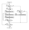
境界電流を再設定するタイミングとして、例えば、エンジンEの始動時(以下、単に始動時と称する)が挙げられる。また、それまでロック解除状態で遅角作動状態や進角作動状態の維持が可能であった境界電流を電磁ソレノイド54に印加したにも関わらず、外部環境の変化やOCV51自体の劣化等の理由により境界電流の値が変化していたためロック状態に切り替わってしまった場合(以下、「意外ロック発生時」と称する)が挙げられる。ただし、再設定を行うのはこれら2つの場合に限るものではなく、例えば、バッテリーを交換した時や、車両点検を受けた時など、任意の場合に境界電流を再設定してもよい。なお、始動時と意外ロック発生時は「内燃機関の所定の作動時」の一例である。
図4に、上述した始動時と意外ロック発生時における境界電流の再設定手順の全体のフローチャートを示す。以下、本願においてフローチャートに示す制御は、ECUにより行われるものとする。ECUにおいて、始動時の再設定を行う前は、遅角側境界電流Iretの再設定終了フラグは0になり再設定が完了したら当該フラグは1になるように設定されている。同様に、再設定を行う前は、進角側境界電流Iadvの再設定終了フラグは0になり、再設定が完了したら当該フラグは1になるように設定されている。また、始動時の境界電流の再設定中において、電磁ソレノイド54に駆動電流Iを印加して遅角作動状態を維持しているときには遅角ロックフラグは0であり、遅角ロック状態に切り替わったときには遅角ロックフラグは1になる。同様に、電磁ソレノイド54に駆動電流Iを印加して進角作動状態を維持しているときには進角ロックフラグは0であり、進角ロック状態に切り替わったときには進角ロックフラグは1になる。
エンジンEが停止しているときは、中間ロック機構8により相対回転位相は中間ロック位相Pでロック状態になっている。車両のイグニッションスイッチをオンにしてエンジンEを始動させると(S401のYes)、電磁ソレノイド54はまだ通電されていないので引き続きロック状態が維持されている。その後、電磁ソレノイド54への通電によりロック解除状態に切り替わり(S402)、遅角側と進角側の初期境界電流の値がそれぞれ設定される(S403)。初期境界電流の値は、相対回転位相を確実に遅角作動状態又は進角作動状態にすることができる値であり、例えば、以前に設定されて正常に作動した境界電流の値でもよい。その後、遅角側境界電流再設定サブルーチン(S404)と、進角側境界電流再設定サブルーチン(S405)を実行する。両方の再設定が完了したら(S406のYes)、再設定のフローを終了し、未完了であれば(S406のNo)再設定が完了するまでサブルーチンの実行を繰り返す。
エンジンEの始動時でなければ(S401のNo)、意外ロック発生時までは再設定は行われない(S407のNo)。意外ロックが発生したら(S407のYes)、意外ロック時境界電流再設定サブルーチン(S408)を行う。
上記の再設定のフローはイグニッションスイッチをオフにしてエンジンEが停止するまで繰り返される(S409のNo)。
〔遅角側境界電流の再設定フロー〕
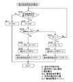
次に、遅角側境界電流再設定サブルーチン(S404)について説明する。図5に、始動時において遅角側境界電流Iretの再設定手順のフローチャートを示し、図7に、当該再設定手順における実相対回転位相φと駆動電流Iのタイムチャートを示す。
次に、遅角側境界電流再設定サブルーチン(S404)について説明する。図5に、始動時において遅角側境界電流Iretの再設定手順のフローチャートを示し、図7に、当該再設定手順における実相対回転位相φと駆動電流Iのタイムチャートを示す。
図7に示すA状態は、車両のイグニッションスイッチをオンにしてエンジンEを始動させた状態である(図4のS401のYes)。このとき電磁ソレノイド54はまだ通電されておらず、実相対回転位相φは中間ロック位相Pでロック状態が維持されている。その後、OCV51が位相保持(W3)状態になるような駆動電流Iを電磁ソレノイド54に印加すると、中間ロック機構8はロック解除状態に切り替えられるが(S402)、実相対回転位相φは中間ロック位相P(正確には±3CA(クランクアングル)の範囲内)が維持されたままである(図7のB状態)。
次に、上述のように遅角作動状態と進角作動状態のそれぞれの初期境界電流(以下、単に初期電流と称する)がECUにより設定され(S403)、遅角側境界電流再設定サブルーチン(S404)が開始される。
遅角側境界電流再設定サブルーチンにおいては、まず、遅角側境界電流の再設定終了フラグにより、既に遅角側境界電流Iretの再設定が完了したか否かを確認し、フラグが0であれば(図5のS501のYes)、遅角作動状態となる初期電流が駆動電流Iとして電磁ソレノイド54に印加される(S502)。初期電流の印加でロック状態に切り替わらなければ(S503のNo)、図7のC状態のように、実相対回転位相φは中間ロック位相Pから遅角方向S2へ変位し、W2状態になる。
実相対回転位相φが遅角側折り返し閾値aよりも進角側にあるときは(S504のNo)、遅角側境界電流再設定サブルーチンの最初に戻り上記フローが繰り返される。繰り返される間に実相対回転位相φが遅角側折り返し閾値aよりも遅角側に変位するので、その状態になれば(S504のYes)、ECUは、初期電流ではロック状態に切り替わらなかった、すなわち、遅角側境界電流Iretの再設定は未完了であると判断する。そして、遅角側境界電流Iretの再設定をするために次回電磁ソレノイド54に印加するときの駆動電流Iの値を、初期電流から遅角側電流変化量αだけ減じた値(第二期電流)と設定する(S505)。遅角側電流変化量αは例えば5mAである。本実施形態においては、初期電流と比べて第二期電流の方がよりロック状態に切り替わりやすい電流である。また、遅角ロックフラグは0のままで(S506)、遅角側境界電流Iretの再設定終了フラグも0のままで、サブルーチン(S404)を終了する。
次に進角側境界電流再設定サブルーチン(図4のS405)が実行される。このサブルーチンの詳細な説明は後述する。このサブルーチンの実行結果に関わらず遅角側境界電流Iretの再設定は未完了なので、再設定は完了しておらず(S406のNo)、進角側境界電流再設定サブルーチンが実行された後、再度、遅角側境界電流再設定サブルーチン(S404)が実行される。
遅角側境界電流再設定サブルーチンの二度目の実行においては、第二期電流が駆動電流Iとして電磁ソレノイド54に印加され(S502)、それでもロック状態に切り替わらなければ(S503のNo)、図7のE状態のように、実相対回転位相φは中間ロック位相Pから遅角方向S2へ変位し、W2状態になる。
実相対回転位相φが遅角側折り返し閾値aよりも遅角側に変位すれば(S504のYes)、ECUは、第二期電流ではロック状態に切り替わらず、遅角側境界電流Iretの再設定は未完了であると判断する。そして、遅角側境界電流Iretの再設定をするために三回目に電磁ソレノイド54に印加するとき駆動電流Iの値を、第二期電流からさらに遅角側電流変化量αだけ減じた値(第三期電流)として(S505)、遅角側境界電流再設定サブルーチンを終了する。
次に、進角側境界電流再設定サブルーチン(S405)が再度実行された後、その後、第三期電流を駆動電流Iとして電磁ソレノイド54に印加する(S502)。第三期電流を印加したときはロック状態に切り替わったので(S503のYes)、図7のG状態のように、実相対回転位相φは中間ロック位相Pに拘束され、W1状態になる。これにより、W2とW1が切り替わる境界の電流は、第二期電流と第三期電流の間にあることが分かった。なお、ロック状態に切り替わったとは、第三期電流を電磁ソレノイド54に印加した後、所定時間の間実相対回転位相φが遅角側折り返し閾値aよりも遅角側に変位しなかったことにより判定される(図7参照)。
この結果より、ロック解除状態からロック状態に切り替わる直前の駆動電流Iである第二期電流を境界電流にしてもよいが、もし第二期電流の方が第三期電流よりもW2とW1の境界に近ければ、今回境界電流を再設定しても、エンジンEの作動中に再び境界電流が変化してしまうおそれがある。そこで、本実施形態においては、第三期電流に遅角側電流変化量αを加え(=第二期電流)、さらに遅角側電流マージンαmを加えた値を遅角側境界電流Iretに設定する(S508)。これにより遅角ロック状態に切り替わったと共に遅角側境界電流Iretの再設定が完了したので、遅角ロックフラグを1にすると共に(S509)、遅角側境界電流Iretの再設定終了フラグも1にして(S510)、サブルーチン(S404)を終了する。なお、遅角側電流変化量αと遅角側電流マージンαmの和は所定の値の一例である。
図7のH状態にあるように、遅角側境界電流Iretの再設定が完了しても、進角側境界電流再設定サブルーチンが終了するまでは、引き続き遅角側境界電流再設定サブルーチンを実行する必要がある。この場合には、既に遅角側境界電流Iretの再設定終了フラグは1なので(S501のNo)、遅角側境界電流Iretを駆動電流Iとして印加する(図5のS511、図7のI状態、K状態)。
〔進角側境界電流の再設定フロー〕
次に、進角側境界電流再設定サブルーチン(図4のS405)について説明する。図6に、始動時において進角側境界電流Iadvの再設定手順のフローチャートを示し、図7に、当該再設定手順における実相対回転位相φと駆動電流Iのタイムチャートを示す。
次に、進角側境界電流再設定サブルーチン(図4のS405)について説明する。図6に、始動時において進角側境界電流Iadvの再設定手順のフローチャートを示し、図7に、当該再設定手順における実相対回転位相φと駆動電流Iのタイムチャートを示す。
図7のC状態のように、実相対回転位相φが中間ロック位相Pから遅角方向S2へ変位(W2状態)し、遅角側境界電流再設定サブルーチンが終了した後、進角側境界電流再設定サブルーチンが実行される。当該サブルーチンにおいては、まず、進角側境界電流の再設定終了フラグにより、既に進角側境界電流Iadvの再設定が完了したか否かを確認し、フラグが0であれば(図6のS601のYes)、既に設定されている進角作動状態となる初期電流が駆動電流Iとして電磁ソレノイド54に印加される(S602、図7のDの状態)。これにより、実相対回転位相φは進角側に向かって変位する。そして初期電流の印加でロック状態に切り替わらなければ(S603のNo)、実相対回転位相φは中間ロック位相Pを越えて進角側に到達し、W4状態になる。
実相対回転位相φが進角側折り返し閾値bよりも遅角側にあるときは(S604のNo)、サブルーチンの最初に戻り上記フローが繰り返される。繰り返される間に実相対回転位相φが進角側折り返し閾値bよりも進角側に変位するので、その状態になれば(S604のYes)、ECUは、初期電流ではロック状態に切り替わらなかった、すなわち、進角側境界電流Iadvの再設定は未完了であると判断する。そして、進角側境界電流Iadvの再設定をするために次回電磁ソレノイド54に印加するとき駆動電流Iの値を、初期電流に進角側電流変化量βだけ加えた値(第二期電流)とする(S605)。進角側電流変化量βは例えば5mAである。本実施形態においては、初期電流と比べて第二期電流の方がよりロック状態に切り替わりやすい電流である。また、進角ロックフラグは0のままで(S606)、進角側境界電流Iadvの再設定終了フラグも0のままで(S607)、サブルーチン(S405)を終了する。
次に上述した遅角側境界電流再設定サブルーチンが実行される。このサブルーチンの実行結果に関わらず進角側境界電流Iadvの再設定は未完了なので、再設定は完了しておらず(S406のNo)、遅角側境界電流再設定サブルーチンが実行された後、再度、進角側境界電流再設定サブルーチンが実行される。
進角側境界電流再設定サブルーチンの二度目の実行においては、第二期電流が駆動電流Iとして電磁ソレノイド54に印加され(S602)、それでもロック状態に切り替わらなければ(S603のNo)、図7のF状態のように、実相対回転位相φは中間ロック位相Pから進角方向S1へ変位し、W4状態になる。
実相対回転位相φが進角側折り返し閾値bよりも進角側に変位すれば(S604のYes)、ECUは、第二期電流ではロック状態に切り替わらず、進角側境界電流Iadvの再設定は未完了と判断する。そして、進角側境界電流Iadvの再設定をするために三回目に電磁ソレノイド54に印加するとき駆動電流Iの値を、第二期電流にさらに進角側電流変化量βだけ加えた値(第三期電流)として(S605)、進角側境界電流再設定サブルーチンを終了する。
このようにして、遅角側境界電流再設定サブルーチンと進角側境界電流再設定サブルーチンとを交互に実行する。そして、進角側境界電流再設定サブルーチンにおいて、図7のJ状態で示すように、第三期電流にさらに進角側電流変化量βだけ加えた第四期電流を駆動電流Iとして電磁ソレノイド54に印加してもロック状態には切り替わらなかった。図7のL状態で示すように、第四期電流にさらに進角側電流変化量βだけ加えた第五期電流を駆動電流Iとして電磁ソレノイド54に印加したときはロック状態に切り替わったので(S603のYes)、実相対回転位相φは中間ロック位相Pに拘束され、W5状態になる。これにより、W4とW5が切り替わる境界の電流は、第四期電流と第五期電流の間にあることが分かった。なお、ロック状態に切り替わったことは、第五期電流を電磁ソレノイド54に印加した後、所定時間の間実相対回転位相φが進角側折り返し閾値bよりも進角側に変位しなかったことにより判定される(図7参照)。
この結果より、ロック解除状態からロック状態に切り替わる直前の駆動電流Iである第四期電流を境界電流にしてもよいが、もし第四期電流の方が第五期電流よりもW5とW4の境界に近ければ、今回進角側境界電流Iadvを再設定しても、エンジンEの作動中に再び境界電流が変化してしまうおそれがある。そこで、本実施形態においては、第五期電流から進角側電流変化量βを減じ(=第四期電流)、さらに進角側電流マージンβmを減じた値を進角側境界電流Iadvに設定する(S608)。これにより進角ロック状態に切り替わったと共に進角側境界電流Iadvの再設定が完了したので、進角ロックフラグを1にすると共に(S609)、進角側境界電流Iadvの再設定終了フラグも1にして(S610)、進角側境界電流再設定サブルーチンを終了する。進角側電流変化量βと進角側電流マージンβmの和は所定の値の一例である。
遅角側境界電流Iretは図7のG状態のときに既に決まり、遅角側境界電流Iretの再設定終了フラグも1になっているので、遅角側境界電流再設定サブルーチンも終了している。遅角側と進角側の両方の境界電流の再設定が完了したので、再設定フローを一旦終了するが(図4のS406のYes)。再設定フローの終了後は、図7のM状態で示すように、ロック解除された状態で実相対回転位相φを中間ロック位相Pに変位させ、その状態を保持する。
再設定のフローはイグニッションスイッチをオフにしてエンジンEが停止するまで繰り返される(S409のNo)。ただし、エンジンEの始動時でなければ(S401のNo)、意外ロック発生時までは境界電流の再設定は行われない(S407のNo)。
このように、エンジンEの始動時に境界電流を再設定することにより、外部環境の変化やOCV51の劣化等の理由により境界電流に変化が生じていた場合でも、できるだけロック状態に切り替わる近傍で、ロック解除状態を維持することができる駆動電流Iを境界電流に設定することができる。その結果、5つの状態の切り替えの制御を確実に行うことができる。
また、遅角側と進角側に交互に実相対回転位相φを変位させることにより、遅角側境界電流Iretの再設定と進角側境界電流Iadvの再設定とを並行して行うことができ、各々を独立して再設定を行う場合と比較して、再設定を完了するまでの時間を短縮することができる。さらに、ロック解除状態で初期電流から所定の大きさ(遅角側電流変化量αと進角側電流変化量β)だけロック状態に近づくように駆動電流Iを変化させ、ロック状態に切り替わったらその直前に電磁ソレノイド54に印加した駆動電流Iにマージンを考慮して境界電流を規定することにより、ロック解除状態での遅角作動と進角作動を行うことができる駆動電流Iの範囲を広げてOCV51の制御性を高めることができる。
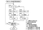
〔意外ロック発生時の境界電流の再設定フロー〕
次に、意外ロック時境界電流再設定サブルーチン(図4のS408)について説明する。図4に示すように、意外ロック発生時はエンジンEの始動時ではないので(S401のNo)、車両走行時等に発生する。図8に、意外ロック発生時において遅角側境界電流Iretの再設定手順のフローチャートを示し、図9に、当該再設定手順における実相対回転位相φと駆動電流Iのタイムチャートを示す。
次に、意外ロック時境界電流再設定サブルーチン(図4のS408)について説明する。図4に示すように、意外ロック発生時はエンジンEの始動時ではないので(S401のNo)、車両走行時等に発生する。図8に、意外ロック発生時において遅角側境界電流Iretの再設定手順のフローチャートを示し、図9に、当該再設定手順における実相対回転位相φと駆動電流Iのタイムチャートを示す。
図9に示すように、A状態では、実相対回転位相φが中間ロック位相Pよりも進角側にあり、その位相が変位しないように保持されている(W3状態)。そこから、中間ロック位相Pを跨いで遅角側に実相対回転位相φを変位させるため、遅角作動状態(W2)になるような駆動電流I(以下、原遅角側境界電流と称する)を電磁ソレノイド54に印加したところ(図9のB状態)、所定の時間が経過しても中間ロック位相Pで拘束されたままで、所望の遅角側の位相に到達しなかった(図9のC状態)。そのため、ECUはOCV51が遅角作動状態(W2)ではなく、遅角ロック状態(W1)になったと判定する。これは、外部環境の変化やOCV51自体の劣化等の理由により遅角側境界電流Iretが増加側に変化していたため、原遅角側境界電流の値が遅角ロック状態の制御範囲になってしまったと考えられる。
そこで、図8に示すような手順で、原遅角側境界電流の値を確実に遅角作動状態になるような新たな遅角側境界電流Iretの値に設定し直す。まず、意に反して中間ロック位相Pになって所定時間経過後に、目標相対回転位相θとこのときの実相対回転位相(=中間ロック位相P)φの大小比較を行い、目標相対回転位相θの方が大きければ(S801のNo)、ECUは、最初は中間ロック位相Pよりも遅角側にあって、進角側に変位しようとしたときに、進角側に到達できずに、中間ロック位相Pでロック状態になったと判定する。また、目標相対回転位相θの方が小さければ(S801のYes)、ECUは、最初は中間ロック位相Pよりも進角側にあって、遅角側に変位しようとしたときに、遅角側に到達できずに、中間ロック位相Pでロック状態になったと判定する。図9は後者の場合を示している。
今後、原遅角側境界電流に対し、二度とロック状態に切り替わらない駆動電流Iの値を新たな遅角側境界電流Iretとして再設定し、電磁ソレノイド54に印加することが必要である。そのため、意外ロック時には、始動時に再設定した遅角側境界電流Iretである、原遅角側境界電流には遅角側電流変化量αと遅角側電流マージンαmの和よりもさらに大きい値である遅角側意外ロック補正値γを加えて、新たな遅角側境界電流Iretにする(S802)。
遅角側境界電流Iretの再設定と並行して、ロック状態をロック解除状態に切り替える必要がある。ただし、今回は、実相対回転位相φを遅角方向S2に向けて変位させている最中にロック状態に切り替わったので、中間ロック機構8の第1ロック部材81は第1凹部85の進角側の壁面に押し付けられている。そのため、位相が保持される(W3)ような駆動電流Iを電磁ソレノイド54に印加しても、単にロック解除流路45から作動油が供給されるだけで第1ロック部材81は進角側の壁面との間の摩擦力により第1凹部85からスムーズに抜けないおそれがある。そこで、第1ロック部材81を第1凹部85の進角側の壁面から離間する方向に実相対回転位相φを変位させつつロック解除するとよい。本実施形態の場合は、進角作動状態(W4)になるような駆動電流Iを電磁ソレノイド54に印加すると、第1ロック部材81を第1凹部85の進角側の壁面から離間させつつ第1ロック部材81を抜くことができる(S803、図9のD状態)。
次に、再度目標相対回転位相θに向けて再設定した遅角側境界電流Iretを電磁ソレノイド54に印加して(S804)、中間ロック位相Pでロック状態に切り替わることなく目標相対回転位相θに到達させることができた(S805のYes、図9のE状態)。目標相対回転位相θに到達した後は、図9のF状態で示すように、その位相を保持する。
これにより、例えば、車両走行中に、それまでロック解除状態で遅角作動状態や進角作動状態の維持が可能であった境界電流を電磁ソレノイド54に印加したにも関わらず、外部環境の変化やOCV51自体の劣化等の理由により境界電流の値が変化していたためロック状態に切り替わってしまった場合にも、迅速に新たな遅角側境界電流Iretの再設定を行い、目標相対回転位相θに到達させることが可能になる。
本実施形態では遅角側境界電流Iretの再設定について説明したが、図8のS806~S808にあるように、進角側境界電流Iadvについても同様のやり方で、進角方向S1に実相対回転位相φを変位させている最中に意図せぬロック状態に切り替わったとしても、迅速に進角側境界電流Iadvの再設定を行って、目標相対回転位相θにスムーズに到達させることができる。
本発明は、内燃機関のクランクシャフトと同期して回転する駆動側回転体に対する従動側回転体の相対回転位相を制御する弁開閉時期制御装置に利用することが可能である。
1 ハウジング(駆動側回転体)
2 内部ロータ(従動側回転体)
8 中間ロック機構
10 弁開閉時期制御装置
51 OCV(電磁弁)
52 スプール
54 電磁ソレノイド(駆動源)
101 カムシャフト
C クランクシャフト(駆動軸)
E エンジン(内燃機関)
Iadv 進角側境界電流(駆動境界電流)
Iret 遅角側境界電流(境界電流)
P 中間ロック位相
X 軸心
2 内部ロータ(従動側回転体)
8 中間ロック機構
10 弁開閉時期制御装置
51 OCV(電磁弁)
52 スプール
54 電磁ソレノイド(駆動源)
101 カムシャフト
C クランクシャフト(駆動軸)
E エンジン(内燃機関)
Iadv 進角側境界電流(駆動境界電流)
Iret 遅角側境界電流(境界電流)
P 中間ロック位相
X 軸心
Claims (7)
- 内燃機関の駆動軸と同期回転する駆動側回転体と、
前記駆動側回転体の内側で前記駆動側回転体の軸心と同軸心に配置され、前記内燃機関の弁開閉用のカムシャフトと一体回転する従動側回転体と、
前記駆動側回転体に対する前記従動側回転体の相対回転位相における最進角位相と最遅角位相の間にある中間ロック位相で供給される作動油によって前記相対回転位相の変位を拘束するロック状態と該ロック状態が解除されたロック解除状態とを選択的に切り替える中間ロック機構と、
駆動源へ印加される駆動電流が変化することによってスプールの位置が変更され、前記スプールの位置に応じて作動油が選択的に供給又は排出されることにより、前記相対回転位相が進角方向又は遅角方向に変位すると共に前記中間ロック機構への作動油の供給と排出とを選択的に切り替える電磁弁とを備え、
前記内燃機関の所定の作動時において、前記駆動電流が変化することによって前記ロック解除状態から前記ロック状態に切り替わったときの前記駆動電流の値に対して、所定の値だけ異なり、且つ、前記ロック解除状態を維持する前記駆動電流の値が境界電流に設定されるように構成される弁開閉時期制御装置。 - 前記相対回転位相が前記中間ロック位相を跨いで進角方向へ変位する進角変位と、前記相対回転位相が前記中間ロック位相を跨いで遅角方向へ変位する遅角変位とが交互に発生するように前記駆動電流を変化させる請求項1に記載の弁開閉時期制御装置。
- 前記進角変位と前記遅角変位との少なくとも一方が複数回発生する場合に、連続する2回の同方向へ変位するときの前記駆動電流の値は、先の前記駆動電流の値よりも後の前記駆動電流の値の方が前記ロック状態に切り替わる値に近くなるように設定される請求項2に記載の弁開閉時期制御装置。
- 前記進角変位と前記遅角変位のいずれかのときに前記ロック状態に切り替わった場合は、その後に前記ロック状態に切り替わった方向に変位するときに印加される前記駆動電流の値は前記境界電流である請求項2又は3に記載の弁開閉時期制御装置。
- 前記所定の作動時とは、前記内燃機関の始動時である請求項1~4のいずれか一項に記載の弁開閉時期制御装置。
- 前記所定の作動時とは、前記ロック解除状態を維持する前記駆動電流を印加したにも関わらず前記ロック状態に切り替わった時である請求項1に記載の弁開閉時期制御装置。
- 前記所定の作動時が前記内燃機関の始動時である場合の前記所定の値よりも、前記所定の作動時が前記ロック解除状態を維持する前記駆動電流を印加したにも関わらず前記ロック状態に切り替わった時である場合の前記所定の値の方が大きい請求項1に記載の弁開閉時期制御装置。
Priority Applications (3)
| Application Number | Priority Date | Filing Date | Title |
|---|---|---|---|
| EP15886449.6A EP3276132B1 (en) | 2015-03-23 | 2015-09-25 | Valve open/close period control device |
| CN201580077365.7A CN107429580B (zh) | 2015-03-23 | 2015-09-25 | 阀正时控制装置 |
| US15/558,091 US10550736B2 (en) | 2015-03-23 | 2015-09-25 | Valve opening and closing timing control apparatus |
Applications Claiming Priority (2)
| Application Number | Priority Date | Filing Date | Title |
|---|---|---|---|
| JP2015059588A JP6402663B2 (ja) | 2015-03-23 | 2015-03-23 | 弁開閉時期制御装置 |
| JP2015-059588 | 2015-03-23 |
Publications (1)
| Publication Number | Publication Date |
|---|---|
| WO2016151897A1 true WO2016151897A1 (ja) | 2016-09-29 |
Family
ID=56977183
Family Applications (1)
| Application Number | Title | Priority Date | Filing Date |
|---|---|---|---|
| PCT/JP2015/077089 Ceased WO2016151897A1 (ja) | 2015-03-23 | 2015-09-25 | 弁開閉時期制御装置 |
Country Status (5)
| Country | Link |
|---|---|
| US (1) | US10550736B2 (ja) |
| EP (1) | EP3276132B1 (ja) |
| JP (1) | JP6402663B2 (ja) |
| CN (1) | CN107429580B (ja) |
| WO (1) | WO2016151897A1 (ja) |
Cited By (1)
| Publication number | Priority date | Publication date | Assignee | Title |
|---|---|---|---|---|
| US20180051599A1 (en) * | 2015-03-23 | 2018-02-22 | Aisin Seiki Kabushiki Kaisha | Valve opening and closing timing control apparatus |
Families Citing this family (4)
| Publication number | Priority date | Publication date | Assignee | Title |
|---|---|---|---|---|
| JP6673167B2 (ja) * | 2016-11-29 | 2020-03-25 | 株式会社デンソー | バルブタイミング調整装置、および、バルブタイミング調整装置の製造方法 |
| JP2019085940A (ja) * | 2017-11-08 | 2019-06-06 | アイシン精機株式会社 | 弁開閉時期制御装置 |
| JP2019199870A (ja) | 2018-05-18 | 2019-11-21 | アイシン精機株式会社 | 弁開閉時期制御装置 |
| JP2019203494A (ja) * | 2018-05-18 | 2019-11-28 | アイシン精機株式会社 | 弁開閉時期制御装置 |
Citations (3)
| Publication number | Priority date | Publication date | Assignee | Title |
|---|---|---|---|---|
| JP2003172109A (ja) * | 2001-12-05 | 2003-06-20 | Aisin Seiki Co Ltd | 弁開閉時期制御装置 |
| JP2006170024A (ja) * | 2004-12-14 | 2006-06-29 | Aisin Seiki Co Ltd | 弁開閉時期制御装置 |
| JP2008255914A (ja) * | 2007-04-06 | 2008-10-23 | Denso Corp | バルブタイミング調整装置及びバルブタイミング調整装置用の電子制御装置 |
Family Cites Families (5)
| Publication number | Priority date | Publication date | Assignee | Title |
|---|---|---|---|---|
| JP4126600B2 (ja) | 2002-09-26 | 2008-07-30 | アイシン精機株式会社 | 弁開閉時期制御装置の制御機構 |
| JP5013323B2 (ja) | 2008-12-09 | 2012-08-29 | 株式会社デンソー | 内燃機関の可変バルブタイミング制御装置 |
| JP5994297B2 (ja) * | 2012-03-08 | 2016-09-21 | アイシン精機株式会社 | 弁開閉時期制御装置 |
| JP5851898B2 (ja) * | 2012-03-21 | 2016-02-03 | 日立オートモティブシステムズ株式会社 | 可変バルブタイミング機構の制御装置 |
| JP6402663B2 (ja) * | 2015-03-23 | 2018-10-10 | アイシン精機株式会社 | 弁開閉時期制御装置 |
-
2015
- 2015-03-23 JP JP2015059588A patent/JP6402663B2/ja not_active Expired - Fee Related
- 2015-09-25 US US15/558,091 patent/US10550736B2/en not_active Expired - Fee Related
- 2015-09-25 CN CN201580077365.7A patent/CN107429580B/zh not_active Expired - Fee Related
- 2015-09-25 EP EP15886449.6A patent/EP3276132B1/en not_active Not-in-force
- 2015-09-25 WO PCT/JP2015/077089 patent/WO2016151897A1/ja not_active Ceased
Patent Citations (3)
| Publication number | Priority date | Publication date | Assignee | Title |
|---|---|---|---|---|
| JP2003172109A (ja) * | 2001-12-05 | 2003-06-20 | Aisin Seiki Co Ltd | 弁開閉時期制御装置 |
| JP2006170024A (ja) * | 2004-12-14 | 2006-06-29 | Aisin Seiki Co Ltd | 弁開閉時期制御装置 |
| JP2008255914A (ja) * | 2007-04-06 | 2008-10-23 | Denso Corp | バルブタイミング調整装置及びバルブタイミング調整装置用の電子制御装置 |
Cited By (2)
| Publication number | Priority date | Publication date | Assignee | Title |
|---|---|---|---|---|
| US20180051599A1 (en) * | 2015-03-23 | 2018-02-22 | Aisin Seiki Kabushiki Kaisha | Valve opening and closing timing control apparatus |
| US10550736B2 (en) * | 2015-03-23 | 2020-02-04 | Aisin Seiki Kabushiki Kaisha | Valve opening and closing timing control apparatus |
Also Published As
| Publication number | Publication date |
|---|---|
| EP3276132A4 (en) | 2018-04-11 |
| CN107429580B (zh) | 2019-07-30 |
| EP3276132B1 (en) | 2019-03-27 |
| US20180051599A1 (en) | 2018-02-22 |
| CN107429580A (zh) | 2017-12-01 |
| JP2016180318A (ja) | 2016-10-13 |
| US10550736B2 (en) | 2020-02-04 |
| EP3276132A1 (en) | 2018-01-31 |
| JP6402663B2 (ja) | 2018-10-10 |
Similar Documents
| Publication | Publication Date | Title |
|---|---|---|
| JP6402663B2 (ja) | 弁開閉時期制御装置 | |
| JP5979115B2 (ja) | 弁開閉時期制御装置 | |
| WO2010109971A1 (ja) | 弁開閉時期制御装置 | |
| US9903235B2 (en) | Valve timing control apparatus | |
| JP2013047504A (ja) | ソレノイドバルブ及び弁開閉時期制御装置 | |
| JP2013015057A (ja) | バルブ特性調整装置 | |
| JP2015028308A (ja) | 弁開閉時期制御装置 | |
| JP2009068500A (ja) | 内燃機関用バルブタイミング調整装置 | |
| WO2013129110A1 (ja) | 内燃機関の可変バルブタイミング制御装置 | |
| JP5979093B2 (ja) | 弁開閉時期制御装置 | |
| JP6141435B2 (ja) | バルブタイミング調整装置の制御装置 | |
| JP5793107B2 (ja) | 内燃機関の可変動弁装置 | |
| JP7439803B2 (ja) | バルブタイミング調整システムおよび電子制御装置 | |
| US20210172347A1 (en) | Valve opening and closing timing control device | |
| JP6589342B2 (ja) | 弁開閉時期制御装置 | |
| WO2015129484A1 (ja) | ソレノイドバルブ | |
| US10526930B2 (en) | Valve timing control system and control command unit | |
| JP5974517B2 (ja) | 弁開閉時期制御装置 | |
| JP6104392B2 (ja) | バルブタイミング調整装置 | |
| JP2015124620A (ja) | 制御弁 | |
| JP2020183746A (ja) | 弁開閉時期制御装置 | |
| US20170298788A1 (en) | Valve opening/closing timing control apparatus | |
| JP2019199871A (ja) | 弁開閉時期制御装置 | |
| JP2018053734A (ja) | 弁開閉時期制御装置 | |
| JP2018119431A (ja) | 弁開閉時期制御装置 |
Legal Events
| Date | Code | Title | Description |
|---|---|---|---|
| 121 | Ep: the epo has been informed by wipo that ep was designated in this application |
Ref document number: 15886449 Country of ref document: EP Kind code of ref document: A1 |
|
| REEP | Request for entry into the european phase |
Ref document number: 2015886449 Country of ref document: EP |
|
| WWE | Wipo information: entry into national phase |
Ref document number: 15558091 Country of ref document: US |
|
| NENP | Non-entry into the national phase |
Ref country code: DE |