WO2016152223A1 - 防振装置 - Google Patents
防振装置 Download PDFInfo
- Publication number
- WO2016152223A1 WO2016152223A1 PCT/JP2016/051731 JP2016051731W WO2016152223A1 WO 2016152223 A1 WO2016152223 A1 WO 2016152223A1 JP 2016051731 W JP2016051731 W JP 2016051731W WO 2016152223 A1 WO2016152223 A1 WO 2016152223A1
- Authority
- WO
- WIPO (PCT)
- Prior art keywords
- actuator
- housing
- vibration
- mounting
- actuator case
- Prior art date
- Legal status (The legal status is an assumption and is not a legal conclusion. Google has not performed a legal analysis and makes no representation as to the accuracy of the status listed.)
- Ceased
Links
Images

Classifications
-
- F—MECHANICAL ENGINEERING; LIGHTING; HEATING; WEAPONS; BLASTING
- F16—ENGINEERING ELEMENTS AND UNITS; GENERAL MEASURES FOR PRODUCING AND MAINTAINING EFFECTIVE FUNCTIONING OF MACHINES OR INSTALLATIONS; THERMAL INSULATION IN GENERAL
- F16F—SPRINGS; SHOCK-ABSORBERS; MEANS FOR DAMPING VIBRATION
- F16F15/00—Suppression of vibrations in systems; Means or arrangements for avoiding or reducing out-of-balance forces, e.g. due to motion
- F16F15/02—Suppression of vibrations of non-rotating, e.g. reciprocating systems; Suppression of vibrations of rotating systems by use of members not moving with the rotating systems
- F16F15/022—Suppression of vibrations of non-rotating, e.g. reciprocating systems; Suppression of vibrations of rotating systems by use of members not moving with the rotating systems using dampers and springs in combination
-
- B—PERFORMING OPERATIONS; TRANSPORTING
- B60—VEHICLES IN GENERAL
- B60K—ARRANGEMENT OR MOUNTING OF PROPULSION UNITS OR OF TRANSMISSIONS IN VEHICLES; ARRANGEMENT OR MOUNTING OF PLURAL DIVERSE PRIME-MOVERS IN VEHICLES; AUXILIARY DRIVES FOR VEHICLES; INSTRUMENTATION OR DASHBOARDS FOR VEHICLES; ARRANGEMENTS IN CONNECTION WITH COOLING, AIR INTAKE, GAS EXHAUST OR FUEL SUPPLY OF PROPULSION UNITS IN VEHICLES
- B60K5/00—Arrangement or mounting of internal-combustion or jet-propulsion units
- B60K5/12—Arrangement of engine supports
- B60K5/1208—Resilient supports
-
- B—PERFORMING OPERATIONS; TRANSPORTING
- B60—VEHICLES IN GENERAL
- B60K—ARRANGEMENT OR MOUNTING OF PROPULSION UNITS OR OF TRANSMISSIONS IN VEHICLES; ARRANGEMENT OR MOUNTING OF PLURAL DIVERSE PRIME-MOVERS IN VEHICLES; AUXILIARY DRIVES FOR VEHICLES; INSTRUMENTATION OR DASHBOARDS FOR VEHICLES; ARRANGEMENTS IN CONNECTION WITH COOLING, AIR INTAKE, GAS EXHAUST OR FUEL SUPPLY OF PROPULSION UNITS IN VEHICLES
- B60K5/00—Arrangement or mounting of internal-combustion or jet-propulsion units
- B60K5/12—Arrangement of engine supports
- B60K5/1283—Adjustable supports, e.g. the mounting or the characteristics being adjustable
-
- F—MECHANICAL ENGINEERING; LIGHTING; HEATING; WEAPONS; BLASTING
- F16—ENGINEERING ELEMENTS AND UNITS; GENERAL MEASURES FOR PRODUCING AND MAINTAINING EFFECTIVE FUNCTIONING OF MACHINES OR INSTALLATIONS; THERMAL INSULATION IN GENERAL
- F16F—SPRINGS; SHOCK-ABSORBERS; MEANS FOR DAMPING VIBRATION
- F16F13/00—Units comprising springs of the non-fluid type as well as vibration-dampers, shock-absorbers, or fluid springs
- F16F13/04—Units comprising springs of the non-fluid type as well as vibration-dampers, shock-absorbers, or fluid springs comprising both a plastics spring and a damper, e.g. a friction damper
-
- F—MECHANICAL ENGINEERING; LIGHTING; HEATING; WEAPONS; BLASTING
- F16—ENGINEERING ELEMENTS AND UNITS; GENERAL MEASURES FOR PRODUCING AND MAINTAINING EFFECTIVE FUNCTIONING OF MACHINES OR INSTALLATIONS; THERMAL INSULATION IN GENERAL
- F16F—SPRINGS; SHOCK-ABSORBERS; MEANS FOR DAMPING VIBRATION
- F16F15/00—Suppression of vibrations in systems; Means or arrangements for avoiding or reducing out-of-balance forces, e.g. due to motion
- F16F15/02—Suppression of vibrations of non-rotating, e.g. reciprocating systems; Suppression of vibrations of rotating systems by use of members not moving with the rotating systems
- F16F15/03—Suppression of vibrations of non-rotating, e.g. reciprocating systems; Suppression of vibrations of rotating systems by use of members not moving with the rotating systems using magnetic or electromagnetic means
-
- F—MECHANICAL ENGINEERING; LIGHTING; HEATING; WEAPONS; BLASTING
- F16—ENGINEERING ELEMENTS AND UNITS; GENERAL MEASURES FOR PRODUCING AND MAINTAINING EFFECTIVE FUNCTIONING OF MACHINES OR INSTALLATIONS; THERMAL INSULATION IN GENERAL
- F16F—SPRINGS; SHOCK-ABSORBERS; MEANS FOR DAMPING VIBRATION
- F16F15/00—Suppression of vibrations in systems; Means or arrangements for avoiding or reducing out-of-balance forces, e.g. due to motion
- F16F15/02—Suppression of vibrations of non-rotating, e.g. reciprocating systems; Suppression of vibrations of rotating systems by use of members not moving with the rotating systems
- F16F15/04—Suppression of vibrations of non-rotating, e.g. reciprocating systems; Suppression of vibrations of rotating systems by use of members not moving with the rotating systems using elastic means
- F16F15/08—Suppression of vibrations of non-rotating, e.g. reciprocating systems; Suppression of vibrations of rotating systems by use of members not moving with the rotating systems using elastic means with rubber springs ; with springs made of rubber and metal
-
- F—MECHANICAL ENGINEERING; LIGHTING; HEATING; WEAPONS; BLASTING
- F16—ENGINEERING ELEMENTS AND UNITS; GENERAL MEASURES FOR PRODUCING AND MAINTAINING EFFECTIVE FUNCTIONING OF MACHINES OR INSTALLATIONS; THERMAL INSULATION IN GENERAL
- F16F—SPRINGS; SHOCK-ABSORBERS; MEANS FOR DAMPING VIBRATION
- F16F7/00—Vibration-dampers; Shock-absorbers
- F16F7/10—Vibration-dampers; Shock-absorbers using inertia effect
- F16F7/1005—Vibration-dampers; Shock-absorbers using inertia effect characterised by active control of the mass
- F16F7/1011—Vibration-dampers; Shock-absorbers using inertia effect characterised by active control of the mass by electromagnetic means
Definitions
- the present invention relates to a vibration isolator.
- This application claims priority based on Japanese Patent Application No. 2015-64062 for which it applied to Japan on March 26, 2015, and uses the content here.
- Patent Document 1 a first mounting member connected to one of a vibration generating unit and a vibration receiving unit, a second mounting member connected to the other, and input vibration
- the actuator is attenuated and absorbed by reciprocating the mover in accordance with the actuator, the actuator case that houses the actuator inside, the actuator case, and the actuator connector and the external power supply are electrically connected
- a vibration isolator in which an actuator case is formed by insert molding using the terminal as an insert product.
- the conventional vibration isolator has a problem that it is difficult to manufacture the actuator case because it is formed by insert molding using a terminal as an insert.
- the present invention has been made in view of such circumstances, and an object of the present invention is to provide a vibration isolator that can be easily manufactured while maintaining the internal sealing performance of the actuator case.
- the vibration isolator of the present invention includes a first mounting member connected to one of the vibration generating unit and the vibration receiving unit, a second mounting member connected to the other, and a mover according to input vibration.
- An actuator that attenuates and absorbs input vibration by reciprocating, an actuator case that houses the actuator, and a relay connector that is attached to the actuator case and electrically connects the connector of the actuator and an external power source
- the relay connector comprises a terminal for connecting the connector of the actuator and the external power source, and a housing in which the terminal is housed, and the actuator case includes the An insertion hole is formed through which the terminal is inserted, and a mounting cylinder surrounding the insertion hole protrudes. Is, inside one of of said hollow mounting and the housing, the other is fitted airtightly through the packing.
- the actuator case can be easily manufactured while maintaining the sealing performance inside the actuator case.
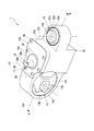
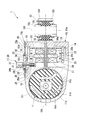
- FIG. 2 is a cross-sectional view of the vibration isolator of FIG. 1 taken along line II-II.
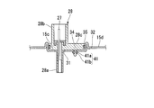
- the vibration isolator shown in FIG. 1 and FIG. 2 it is a part of top view which looked at the cover body from the inner side of an actuator case.
- the vibration isolator 1 includes a first mounting member 11 connected to one of a vibration generating unit and a vibration receiving unit, a second mounting member 12 connected to the other, and a mover according to input vibration.
- the actuator 14 that attenuates and absorbs input vibration by reciprocating the actuator 13, the actuator case 15 that accommodates the actuator 14 inside, the connector 16 of the actuator 14 and an external power source (not shown) And a relay connector 17 for electrically connecting the two.
- the first mounting member 11 and the second mounting member 12 are respectively an inner cylinder 11a, 12a, an outer cylinder 11b, 12b that surrounds the inner cylinder 11a, 12a from the outside in the radial direction, an inner cylinder 11a, 12a, and an outer cylinder 11b. , 12b, and elastic bodies 11c, 12c.
- the inner cylinders 11a and 12a and the outer cylinders 11b and 12b are made of, for example, a metal material or a resin material, and the elastic bodies 11c and 12c are made of, for example, a rubber material.
- the first attachment member 11 is formed with a larger diameter than the second attachment member 12.
- the outer cylinder 11 b of the first attachment member 11 is formed to have a larger diameter than the outer cylinder 12 b of the second attachment member 12.
- the volume of the elastic body 11 c of the first mounting member 11 is larger than that of the elastic body 12 c of the second mounting member 12.
- the spring constant of the first attachment member 11 is lower than the spring constant of the second attachment member 12.
- the first central axis O1 is a connecting axis that connects the second central axis O2 to the first central axis O1 and the second central axis O2, and is orthogonal to both the first central axis O1 and the second central axis O2. It extends in parallel along the imaginary axis when rotated 90 ° around O3.
- the vibration isolator 1 is configured such that, for example, when the first central axis O1 extends in the horizontal direction, the second central axis O2 extends in the vertical direction.
- the actuator 14 has a support shaft 18 extending in the direction of the connection axis O3, an annular core 19 fitted to the support shaft 18 from the outside, and is fitted to the support shaft 18 from the outside, and the winding core 19 is connected to the connection axis.
- Two annular holders 20 sandwiched in the O3 direction, coils 21 held by the respective holders 20, a cylindrical mover 13 surrounding the winding core 19 and the holder 20 over the entire circumference around the connecting axis O3, and movable
- a plurality of pairs of permanent magnets 23 disposed on the inner peripheral surface of the child 13 and an elastic support 22 for connecting the mover 13 and the support shaft 18 are provided.
- Both ends of the support shaft 18 in the direction of the connecting axis O3 are fitted in mounting holes formed in portions of the inner surface of the actuator case 15 that are opposed to each other in the direction of the connecting axis O3.
- the holder 20 connects the inner cylinder 20a fitted to the support shaft 18 from the outside, the outer cylinder 20b surrounding the inner cylinder 20a, and the ends on the core 19 side of the inner cylinder 20a and the outer cylinder 20b. Connecting plate 20c.
- the holder 20 is provided with a connector 16 for supplying power to the coil 21. A part of the connector 16 protrudes from the holder 20 toward the other end opening 15e of the actuator case 15 described later.
- the holder 20 is provided with a surrounding cylinder 24 that protrudes toward the other end opening 15 e of the actuator case 15 and surrounds the part of the connector 16.
- the part of the surrounding cylinder 24 and the connector 16 is disposed on the outer cylinder 20b of the two holders 20 located on the first mounting member 11 side.
- the mover 13 is disposed in the actuator case 15 so as to be able to reciprocate so as to approach one of the first mounting member 11 and the second mounting member 12 and to be separated from the other.
- the mover 13 is disposed so as to be able to reciprocate along the direction of the connecting axis O3.
- the pair of permanent magnets 23 are arranged such that opposite magnetic poles face each other across the connecting axis O3.
- a plurality of pairs of permanent magnets 23 are arranged continuously along the direction of the connecting axis O3, and in each permanent magnet 23 adjacent in this direction, opposite magnetic poles are adjacent to each other.
- the elastic support body 22 is formed in a plate shape that can be elastically deformed, and a through-hole into which the support shaft 18 is fitted is formed. The elastic support 22 is connected to the end of the mover 13 on the second attachment member 12 side.
- the actuator case 15 connects the first mounting member 11 and the second mounting member 12.
- the outer cylinders 11 b and 12 b of the first attachment member 11 and the second attachment member 12 are fitted in the outer cylinders 11 d and 12 d, and the outer cylinders 11 d and 12 d are connected to the actuator case 15. It is integrally formed.
- the actuator case 15 is formed in a cylindrical shape with one end closed and the other end opened, and a main body portion 15a in which the actuator 14 is accommodated, and a lid body 15b for closing the other end opening 15e of the main body portion 15a. And.
- the main body 15a and the lid 15b may be integrally formed.
- the actuator case 15 is formed in a cylindrical shape extending in parallel with the second central axis O2.
- An annular seal rubber 25 is disposed between the peripheral edge of the other end opening 15e in the main body 15a and the lid 15b.
- the lid body 15b is fixed to the main body portion 15a by a plurality of screws 26.
- the relay connector 17 includes a terminal 27 that connects the connector 16 of the actuator 14 and an external power source (not shown), and a housing 28 in which the terminal 27 is housed.
- the housing 28 is formed in a cylindrical shape extending in parallel with the second central axis O2, and the terminal 27 is formed in a rod shape extending in parallel with the second central axis O2.
- the housing 28 is located between the inner connecting portion 28a fitted to the surrounding cylinder 24 of the actuator 14, the outer connecting portion 28b protruding outward from the actuator case 15, and the inner connecting portion 28a and the outer connecting portion 28b. , And a flange portion 28c protruding outward in the radial direction.
- the housing 28 is integrally formed of, for example, a thermoplastic resin.
- the actuator case 15 is formed with an insertion hole 31 into which the terminal 27 of the relay connector 17 is inserted, and a mounting cylinder 32 surrounding the insertion hole 31 is provided so as to protrude.
- an insertion hole 31 is formed in the lid body 15b.
- the inner coupling portion 28 a of the housing 28 is inserted into the insertion hole 31, and the inner coupling portion 28 a is fitted into the surrounding cylinder 24 of the actuator 14 through the insertion hole 31, so that the terminal 27 is connected to the actuator 14.
- the mounting cylinder 32 extends in parallel with the second central axis O2.
- a portion (hereinafter referred to as an inner portion) 15c located inside the mounting cylinder 32 is located inside the actuator case 15 more than a portion (hereinafter referred to as an outer portion) 15d positioned outside the mounting cylinder 32. It is overhanging.
- the inner portion 15c may protrude beyond the actuator case 15 from the outer portion 15d.
- the other of the mounting cylinder 32 and the housing 28 is airtightly fitted inside the one of the mounting cylinder 32 and the housing 28 via an annular packing 35.
- the flange portion 28 c of the housing 28 is fitted into the mounting cylinder 32 via the packing 35.
- a cylinder may be provided in the housing 28, and the mounting cylinder 32 may be fitted therein.
- the mounting cylinder 32 is formed in a cylindrical shape, and the packing 35 is formed in an annular shape. Thereby, the radial compressive force applied to the packing 35 can be made uniform over the entire circumference.
- An annular groove extending over the entire circumference is formed on the outer peripheral surface of the flange portion 28c, and a packing 35 is fitted in the annular groove.
- the packing 35 is entirely covered with the mounting cylinder 32 and the flange portion 28c. Further, the packing 35 is not limited to an annular shape that continuously extends over the entire circumference, and may be an annular shape that has a C shape with a part cut away, for example.
- the mounting cylinder 32 protrudes from both the front and back surfaces of the outer portion 15d of the lid body 15b.
- the length of the mounting cylinder 32 can be increased while suppressing the amount of protrusion from the outer portion 15d of the lid 15b of the mounting cylinder 32, and the rigidity of the mounting cylinder 32 can be easily increased. It becomes possible. Therefore, the sealing performance between the mounting cylinder 32 and the housing 28 can be reliably ensured.
- the packing 35 is disposed on a portion of the inner peripheral surface of the mounting cylinder 32 that is located on the same plane as the front and back surfaces of the outer portion 15 d of the lid body 15 b.
- the mounting cylinder 32 is formed by drawing the lid 15b.
- the opening peripheral edge of the mounting cylinder 32 in the outer portion 15d of the lid body 15b is folded back in the direction opposite to the direction in which the lid body 15b is squeezed when the mounting cylinder 32 is formed.
- the mounting cylinder 32 and the lid body 15b may be separated from each other. In this case, the mounting cylinder 32 and the lid body 15b may be bonded or welded. Further, when the mounting cylinder 32 and the lid body 15b are integrated, they may be formed by casting or injection molding.
- an attachment hole 34 into which the fitting protrusion 33 formed on the housing 28 is fitted is formed in the inner portion 15c of the lid 15b.
- a plurality of fitting protrusions 33 are formed on the flange portion 28 c of the housing 28 and protrude toward the inside of the actuator case 15.
- the fitting protrusion 33 initially has a rod shape as shown by a two-dot chain line in FIG. 2 and FIG. 3 after being fitted into the mounting hole 34.
- a portion protruding from the back surface of the lid body 15b to the inside of the actuator case 15 is heated and crushed toward the back surface of the lid body 15b to be expanded into a locking portion and adhered to the back surface of the lid body 15b.
- the flange 28c and the fitting protrusion 33 sandwich the inner portion 15c of the lid 15b, so that the housing 28 is fixed to the lid 15b.
- the fitting protrusion 33 does not need to adhere
- the vibration isolator 1 described above When the vibration isolator 1 described above is disposed in the vehicle so that vibration is input in the direction of the connecting axis O3, when a vibration having a frequency component that cannot be absorbed by the first mounting member 11 is input, the mover The input vibration is attenuated and absorbed by reciprocating 13 in the direction of the connecting axis O3 with the amplitude and frequency calculated by the control means (not shown) in phase opposite to the input vibration.
- the first mounting member 11 causes much of the input vibration from the engine. Attenuates and absorbs. Therefore, the specification of the actuator 14 can be suppressed to the minimum necessary, and an increase in the cost of the vibration isolator 1 can be suppressed.
- the vibration isolator 1 since the housing 28 is airtightly fitted in the mounting cylinder 32 via the annular packing 35, the vibration is input to the vibration isolator 1. Even if the housing 28 is deformed or displaced with respect to the actuator case 15 due to vibration, as long as the housing 28 is fitted in the mounting cylinder 32, the inner peripheral surface of the mounting cylinder 32 and the housing 28 It becomes possible to make it difficult to release the sealing property between the outer peripheral surface of the first and second outer surfaces. Therefore, communication through the insertion hole 31 between the inside and outside of the actuator case 15 can be easily and reliably prevented.
- the vibration isolator 1 can be easily manufactured as compared with a case where the actuator case is formed by insert molding using a terminal as an insert.
- the housing 28 is disposed inside the mounting cylinder 32, the protrusion of the housing 28 from the actuator case 15 can be suppressed. Therefore, the bulkiness of the vibration isolator 1 can be suppressed.
- the housing 28 is fitted into the mounting cylinder 32 but also the fitting projection 33 of the housing 28 is fitted into the mounting hole 34 of the actuator case 15, so that the housing 28 is attached to the actuator case 15. It can be firmly fixed.
- the mounting hole 34 is formed in a portion of the actuator case 15 that is positioned inside the mounting cylinder 32 and is hermetically sealed to the outside of the actuator case 15 by the packing 35. Communication between the inside and the outside of the case 15 through the mounting hole 34 can be prevented.
- the present invention is not limited to this, and the tubular first mounting member, the second mounting member disposed radially inside the first mounting member, the first mounting member, and the second mounting member And a movable plate that defines a liquid chamber between the elastic body and a movable member connected to the movable plate. By reciprocating the movable member, the movable plate is vibrated and input.
- the present invention can also be applied to a vibration isolator including an actuator that attenuates and absorbs vibration and an actuator case that accommodates the actuator inside.
- a shaft portion 41a protruding from the flange portion 28c and a tip portion of the shaft portion 41a are formed to be elastically deformable, and the flange portion 28c side from the tip is formed.
- a fitting protrusion 41 having a locking portion 41b that gradually increases in diameter as it goes to the position may be adopted.
- the locking portion 41 b is slidably brought into contact with the peripheral edge of the opening of the mounting hole 34 in the actuator case 15 and deformed to reduce the diameter. When passing through 34, it is restored and deformed. Thereby, the housing 28 is fixed to the lid 15b by the flange portion 28c and the engaging portion 41b of the fitting protrusion 41 sandwiching the inner portion 15c of the lid 15b.
- ADVANTAGE OF THE INVENTION According to this invention, it can manufacture easily, maintaining the sealing performance inside the actuator case.
Landscapes
- Engineering & Computer Science (AREA)
- General Engineering & Computer Science (AREA)
- Mechanical Engineering (AREA)
- Physics & Mathematics (AREA)
- Acoustics & Sound (AREA)
- Aviation & Aerospace Engineering (AREA)
- Chemical & Material Sciences (AREA)
- Combustion & Propulsion (AREA)
- Electromagnetism (AREA)
- Transportation (AREA)
- Combined Devices Of Dampers And Springs (AREA)
- Vibration Prevention Devices (AREA)
Abstract
本発明は、第1取付け部材(11)、および第2取付け部材(12)と、入力振動に応じて可動子(13)を往復動させることにより、入力振動を減衰、吸収させるアクチュエータ(14)と、アクチュエータ(14)を内部に収容するアクチュエータケース(15)と、アクチュエータケース(15)に取り付けられ、アクチュエータ(14)のコネクタ(16)と外部電源とを電気的に接続する中継コネクタ(17)と、を備え、中継コネクタ(17)は、アクチュエータ(14)のコネクタ(16)と外部電源とを接続する端子(27)と、端子(27)が内装されるハウジング(28)と、を備え、アクチュエータケース(15)には、端子(27)が挿通される挿通孔(31)が形成されるとともに、挿通孔(31)を囲繞する装着筒(32)が突出して設けられ、装着筒(32)およびハウジング(28)のうちのいずれか一方の内側に、他方がパッキン(35)を介して気密に嵌合している。
Description
本発明は、防振装置に関する。
本願は、2015年3月26日に日本に出願された特願2015-64062号に基づき優先権を主張し、その内容をここに援用する。
本願は、2015年3月26日に日本に出願された特願2015-64062号に基づき優先権を主張し、その内容をここに援用する。
従来から、例えば下記特許文献1に示されるような、振動発生部および振動受部のうちのいずれか一方に連結される第1取付け部材、および他方に連結される第2取付け部材と、入力振動に応じて可動子を往復動させることにより、入力振動を減衰、吸収させるアクチュエータと、アクチュエータを内部に収容するアクチュエータケースと、アクチュエータケースに取り付けられ、アクチュエータのコネクタと外部電源とを電気的に接続する端子と、を備え、アクチュエータケースが、端子をインサート品としたインサート成形により形成された防振装置が知られている。
しかしながら、前記従来の防振装置では、アクチュエータケースが、端子をインサート品としたインサート成形により形成されているので、その製造が困難であるという問題がある。
この発明は、このような事情を考慮してなされたもので、アクチュエータケースの内部の密封性を維持しつつ、容易に製造することができる防振装置を提供することを目的とする。
本発明の防振装置は、振動発生部および振動受部のうちのいずれか一方に連結される第1取付け部材、および他方に連結される第2取付け部材と、入力振動に応じて可動子を往復動させることにより、入力振動を減衰、吸収させるアクチュエータと、前記アクチュエータを内部に収容するアクチュエータケースと、前記アクチュエータケースに取り付けられ、前記アクチュエータのコネクタと外部電源とを電気的に接続する中継コネクタと、を備える防振装置であって、前記中継コネクタは、前記アクチュエータのコネクタと前記外部電源とを接続する端子と、前記端子が内装されるハウジングと、を備え、前記アクチュエータケースには、前記端子が挿通される挿通孔が形成されるとともに、前記挿通孔を囲繞する装着筒が突出して設けられ、前記装着筒および前記ハウジングのうちのいずれか一方の内側に、他方がパッキンを介して気密に嵌合している。
この発明によれば、アクチュエータケースの内部の密封性を維持しつつ、容易に製造することができる。
以下、本発明に係る防振装置の一実施形態を、図1~図3を参照しながら説明する。
この防振装置1は、振動発生部および振動受部のうちのいずれか一方に連結される第1取付け部材11、および他方に連結される第2取付け部材12と、入力振動に応じて可動子13を往復動させることにより、入力振動を減衰、吸収させるアクチュエータ14と、アクチュエータ14を内部に収容するアクチュエータケース15と、アクチュエータケース15に取り付けられ、アクチュエータ14のコネクタ16と不図示の外部電源とを電気的に接続する中継コネクタ17と、を備えている。
この防振装置1は、振動発生部および振動受部のうちのいずれか一方に連結される第1取付け部材11、および他方に連結される第2取付け部材12と、入力振動に応じて可動子13を往復動させることにより、入力振動を減衰、吸収させるアクチュエータ14と、アクチュエータ14を内部に収容するアクチュエータケース15と、アクチュエータケース15に取り付けられ、アクチュエータ14のコネクタ16と不図示の外部電源とを電気的に接続する中継コネクタ17と、を備えている。
第1取付け部材11および第2取付け部材12はそれぞれ、内筒11a、12aと、内筒11a、12aを径方向の外側から囲繞する外筒11b、12bと、内筒11a、12aと外筒11b、12bとを連結する弾性体11c、12cと、を備えている。なお、内筒11a、12aおよび外筒11b、12bは、例えば金属材料若しくは樹脂材料等で形成され、弾性体11c、12cは、例えばゴム材料等で形成されている。
第1取付け部材11は、第2取付け部材12より大径に形成されている。図示の例では、第1取付け部材11の外筒11bが、第2取付け部材12の外筒12bより大径に形成されている。第1取付け部材11の弾性体11cは、第2取付け部材12の弾性体12cより体積が大きくなっている。第1取付け部材11のばね定数は、第2取付け部材12のばね定数より低くなっている。
第1取付け部材11は、第2取付け部材12より大径に形成されている。図示の例では、第1取付け部材11の外筒11bが、第2取付け部材12の外筒12bより大径に形成されている。第1取付け部材11の弾性体11cは、第2取付け部材12の弾性体12cより体積が大きくなっている。第1取付け部材11のばね定数は、第2取付け部材12のばね定数より低くなっている。
第1取付け部材11では、内筒11a、外筒11b、および弾性体11cがそれぞれ、第1中心軸線O1と同軸に配設され、第2取付け部材12では、内筒12a、外筒12b、および弾性体12cがそれぞれ、第2中心軸線O2と同軸に配設されている。
なお、第1中心軸線O1は、第2中心軸線O2を、第1中心軸線O1と第2中心軸線O2とを結び、かつ第1中心軸線O1および第2中心軸線O2の双方に直交する連結軸線O3を中心に90°回転させたときの仮想軸線に沿って平行に延びている。すなわち、この防振装置1は、例えば第1中心軸線O1が水平方向に延びるように配置された場合、第2中心軸線O2が鉛直方向に延びるように構成されている。
なお、第1中心軸線O1は、第2中心軸線O2を、第1中心軸線O1と第2中心軸線O2とを結び、かつ第1中心軸線O1および第2中心軸線O2の双方に直交する連結軸線O3を中心に90°回転させたときの仮想軸線に沿って平行に延びている。すなわち、この防振装置1は、例えば第1中心軸線O1が水平方向に延びるように配置された場合、第2中心軸線O2が鉛直方向に延びるように構成されている。
アクチュエータ14は、連結軸線O3方向に延びる支持軸18と、支持軸18に外側から嵌合された環状の巻芯19と、支持軸18に外側から嵌合されるとともに、巻芯19を連結軸線O3方向に挟む2つの環状のホルダー20と、各ホルダー20に保持されたコイル21と、巻芯19およびホルダー20を、連結軸線O3回りの全周にわたって囲繞する筒状の可動子13と、可動子13の内周面に配設された複数対の永久磁石23と、可動子13と支持軸18とを連結する弾性支持体22と、を備えている。
支持軸18における連結軸線O3方向の両端部は、アクチュエータケース15の内面のうち、連結軸線O3方向で互いに対向する部分に形成された装着孔にそれぞれ嵌合されている。
ホルダー20は、支持軸18に外側から嵌合された内筒20aと、内筒20aを囲繞する外筒20bと、内筒20aおよび外筒20bにおける巻芯19側の各端部同士を連結する連結板20cと、を備えている。
ホルダー20には、コイル21に給電するためのコネクタ16が配設されている。コネクタ16のうちの一部は、ホルダー20から、後述するアクチュエータケース15の他端開口15eに向けて突出している。ホルダー20には、アクチュエータケース15の他端開口15eに向けて突出し、かつコネクタ16の前記一部を囲繞する囲繞筒24が配設されている。囲繞筒24およびコネクタ16の前記一部は、2つのホルダー20のうち、第1取付け部材11側に位置する方の外筒20bに配設されている。
ホルダー20は、支持軸18に外側から嵌合された内筒20aと、内筒20aを囲繞する外筒20bと、内筒20aおよび外筒20bにおける巻芯19側の各端部同士を連結する連結板20cと、を備えている。
ホルダー20には、コイル21に給電するためのコネクタ16が配設されている。コネクタ16のうちの一部は、ホルダー20から、後述するアクチュエータケース15の他端開口15eに向けて突出している。ホルダー20には、アクチュエータケース15の他端開口15eに向けて突出し、かつコネクタ16の前記一部を囲繞する囲繞筒24が配設されている。囲繞筒24およびコネクタ16の前記一部は、2つのホルダー20のうち、第1取付け部材11側に位置する方の外筒20bに配設されている。
可動子13は、アクチュエータケース15内に、第1取付け部材11および第2取付け部材12のいずれか一方に接近し、かつ他方から離間するように往復動が可能に配設されている。図示の例では、可動子13は、連結軸線O3方向に沿って往復動が可能に配設されている。
一対の永久磁石23は、連結軸線O3を挟んで、相互に逆の磁極が対向するように配設されている。一対の永久磁石23は、連結軸線O3方向に沿って連なって複数配設されており、この方向で隣り合う各永久磁石23では、互いに逆の磁極が隣接している。
弾性支持体22は、弾性変形自在な板状に形成され、支持軸18が嵌合される貫通孔が形成されている。弾性支持体22は、可動子13における第2取付け部材12側の端部に連結されている。
一対の永久磁石23は、連結軸線O3を挟んで、相互に逆の磁極が対向するように配設されている。一対の永久磁石23は、連結軸線O3方向に沿って連なって複数配設されており、この方向で隣り合う各永久磁石23では、互いに逆の磁極が隣接している。
弾性支持体22は、弾性変形自在な板状に形成され、支持軸18が嵌合される貫通孔が形成されている。弾性支持体22は、可動子13における第2取付け部材12側の端部に連結されている。
アクチュエータケース15は、第1取付け部材11と第2取付け部材12とを連結している。図示の例では、第1取付け部材11および第2取付け部材12の各外筒11b、12bは、外郭筒11d、12d内に嵌合しており、各外郭筒11d、12dは、アクチュエータケース15と一体に形成されている。
アクチュエータケース15は、一端が閉塞し、かつ他端が開口した筒状に形成され、その内側にアクチュエータ14が収容された本体部15aと、本体部15aの他端開口15eを閉塞する蓋体15bと、を備えている。なお、本体部15aおよび蓋体15bは一体に形成されてもよい。
図示の例では、アクチュエータケース15は、第2中心軸線O2と平行に延びる筒状に形成されている。本体部15aにおける他端開口15eの周縁部と蓋体15bとの間には、環状のシールゴム25が配設されている。蓋体15bは、複数のビス26により本体部15aに固定されている。
アクチュエータケース15は、一端が閉塞し、かつ他端が開口した筒状に形成され、その内側にアクチュエータ14が収容された本体部15aと、本体部15aの他端開口15eを閉塞する蓋体15bと、を備えている。なお、本体部15aおよび蓋体15bは一体に形成されてもよい。
図示の例では、アクチュエータケース15は、第2中心軸線O2と平行に延びる筒状に形成されている。本体部15aにおける他端開口15eの周縁部と蓋体15bとの間には、環状のシールゴム25が配設されている。蓋体15bは、複数のビス26により本体部15aに固定されている。
中継コネクタ17は、アクチュエータ14のコネクタ16と不図示の外部電源とを接続する端子27と、端子27が内装されるハウジング28と、を備えている。
ハウジング28は、第2中心軸線O2と平行に延びる筒状に形成されていて、端子27は、第2中心軸線O2と平行に延びる棒状に形成されている。ハウジング28は、アクチュエータ14の囲繞筒24に嵌合される内側連結部28aと、アクチュエータケース15から外側に突出する外側連結部28bと、内側連結部28aと外側連結部28bとの間に位置し、その径方向の外側に突出するフランジ部28cと、を備えている。ハウジング28は、例えば熱可塑性樹脂等により一体に形成されている。
ハウジング28は、第2中心軸線O2と平行に延びる筒状に形成されていて、端子27は、第2中心軸線O2と平行に延びる棒状に形成されている。ハウジング28は、アクチュエータ14の囲繞筒24に嵌合される内側連結部28aと、アクチュエータケース15から外側に突出する外側連結部28bと、内側連結部28aと外側連結部28bとの間に位置し、その径方向の外側に突出するフランジ部28cと、を備えている。ハウジング28は、例えば熱可塑性樹脂等により一体に形成されている。
そして、本実施形態では、アクチュエータケース15に、中継コネクタ17の端子27が挿通される挿通孔31が形成されるとともに、挿通孔31を囲繞する装着筒32が突出して設けられている。
図示の例では、蓋体15bに挿通孔31が形成されている。挿通孔31内に、ハウジング28の内側連結部28aが挿通されており、内側連結部28aが、挿通孔31を通してアクチュエータ14の囲繞筒24に嵌合されることにより、端子27が、アクチュエータ14のコネクタ16に電気的に接続する。
装着筒32は、第2中心軸線O2と平行に延びている。蓋体15bのうち、装着筒32の内側に位置する部分(以下、内側部分という)15cは、装着筒32の外側に位置する部分(以下、外側部分という)15dよりもアクチュエータケース15の内側に張り出している。なお、内側部分15cを外側部分15dよりもアクチュエータケース15の外側に張り出させてもよい。
図示の例では、蓋体15bに挿通孔31が形成されている。挿通孔31内に、ハウジング28の内側連結部28aが挿通されており、内側連結部28aが、挿通孔31を通してアクチュエータ14の囲繞筒24に嵌合されることにより、端子27が、アクチュエータ14のコネクタ16に電気的に接続する。
装着筒32は、第2中心軸線O2と平行に延びている。蓋体15bのうち、装着筒32の内側に位置する部分(以下、内側部分という)15cは、装着筒32の外側に位置する部分(以下、外側部分という)15dよりもアクチュエータケース15の内側に張り出している。なお、内側部分15cを外側部分15dよりもアクチュエータケース15の外側に張り出させてもよい。
そして、装着筒32およびハウジング28のうちのいずれか一方の内側に、他方が環状のパッキン35を介して気密に嵌合している。図示の例では、装着筒32内に、ハウジング28のフランジ部28cがパッキン35を介して嵌合されている。なお、ハウジング28に筒体を配設し、その内側に装着筒32を嵌合させてもよい。
装着筒32は円筒状に形成され、パッキン35は円環状に形成されている。これにより、パッキン35に加えられるその径方向の圧縮力を全周にわたって均等にすることができる。
フランジ部28cの外周面には、全周にわたって延びる環状溝が形成されており、この環状溝内にパッキン35が嵌合されている。これにより、パッキン35が、入力振動によって装着筒32に対して位置ずれするのを抑制することができる。
なお、パッキン35は、装着筒32およびフランジ部28cにより全体が覆われている。また、パッキン35は、全周にわたって連続して延びる環状に限らず、例えば一部が切欠かれたC字状を呈する環状であってもよい。
装着筒32は円筒状に形成され、パッキン35は円環状に形成されている。これにより、パッキン35に加えられるその径方向の圧縮力を全周にわたって均等にすることができる。
フランジ部28cの外周面には、全周にわたって延びる環状溝が形成されており、この環状溝内にパッキン35が嵌合されている。これにより、パッキン35が、入力振動によって装着筒32に対して位置ずれするのを抑制することができる。
なお、パッキン35は、装着筒32およびフランジ部28cにより全体が覆われている。また、パッキン35は、全周にわたって連続して延びる環状に限らず、例えば一部が切欠かれたC字状を呈する環状であってもよい。
装着筒32は、蓋体15bの外側部分15dの表裏面の双方に対して突出している。これにより、装着筒32の蓋体15bの外側部分15dからの突出量を抑えつつ、装着筒32の長さを長くすることが可能になるとともに、装着筒32の剛性を容易に高くすることが可能になる。したがって、装着筒32とハウジング28との間のシール性を確実に確保することができる。
パッキン35は、図2に示されるように、装着筒32の内周面のうち、蓋体15bの外側部分15dの表裏面と同一平面上に位置する部分に配設されている。図示の例では、装着筒32は、蓋体15bに絞り加工が施されて形成されている。蓋体15bの外側部分15dにおける装着筒32の開口周縁部は、装着筒32を形成する際に蓋体15bを絞る方向と反対方向に向けて折り返されている。
なお、装着筒32と蓋体15bとは別体としてもよく、この場合、装着筒32と蓋体15bとを接着してもよいし、溶接してもよい。また、装着筒32および蓋体15bを一体とする場合、鋳造、若しくは射出成形等で形成してもよい。
パッキン35は、図2に示されるように、装着筒32の内周面のうち、蓋体15bの外側部分15dの表裏面と同一平面上に位置する部分に配設されている。図示の例では、装着筒32は、蓋体15bに絞り加工が施されて形成されている。蓋体15bの外側部分15dにおける装着筒32の開口周縁部は、装着筒32を形成する際に蓋体15bを絞る方向と反対方向に向けて折り返されている。
なお、装着筒32と蓋体15bとは別体としてもよく、この場合、装着筒32と蓋体15bとを接着してもよいし、溶接してもよい。また、装着筒32および蓋体15bを一体とする場合、鋳造、若しくは射出成形等で形成してもよい。
また、蓋体15bの内側部分15cには、ハウジング28に形成された嵌合突起33が嵌合される取付け孔34が形成されている。
図示の例では、嵌合突起33は、ハウジング28のフランジ部28cに複数形成され、アクチュエータケース15の内側に向けて突出している。嵌合突起33は、取付け孔34に嵌合された当初は、図2、および図3の2点鎖線に示されるような、棒状を呈していて、嵌合後に、嵌合突起33のうち、蓋体15bの裏面からアクチュエータケース15の内側に突出する部分を、加熱して蓋体15bの裏面に向けて押し潰すことにより拡張させて係止部にするとともに、蓋体15bの裏面に接着する。これにより、フランジ部28cと嵌合突起33とが、蓋体15bの内側部分15cを挟み込むことで、ハウジング28が蓋体15bに固着される。なお、嵌合突起33は、蓋体15bの裏面に接着しなくてもよい。
図示の例では、嵌合突起33は、ハウジング28のフランジ部28cに複数形成され、アクチュエータケース15の内側に向けて突出している。嵌合突起33は、取付け孔34に嵌合された当初は、図2、および図3の2点鎖線に示されるような、棒状を呈していて、嵌合後に、嵌合突起33のうち、蓋体15bの裏面からアクチュエータケース15の内側に突出する部分を、加熱して蓋体15bの裏面に向けて押し潰すことにより拡張させて係止部にするとともに、蓋体15bの裏面に接着する。これにより、フランジ部28cと嵌合突起33とが、蓋体15bの内側部分15cを挟み込むことで、ハウジング28が蓋体15bに固着される。なお、嵌合突起33は、蓋体15bの裏面に接着しなくてもよい。
以上の防振装置1を、連結軸線O3方向に振動が入力されるように、車両に配設した状態において、第1取付け部材11では吸収できない周波数成分の振動が入力されたときに、可動子13を、この入力振動と逆位相で、かつ不図示の制御手段で算出された振幅および周波数で、連結軸線O3方向に往復動させることにより、この入力振動が減衰、吸収される。なお、防振装置1を、例えば、連結軸線O3方向が車両前後方向と一致するように車両に配設してもよい。
ここで、大型の第1取付け部材11をエンジン側の部材に取り付け、小型の第2取付け部材12を車体側の部材に取付けることにより、第1取付け部材11が、エンジンからの入力振動の多くを減衰、吸収することとなる。したがって、アクチュエータ14の仕様を必要最小限に抑えることが可能になり、防振装置1のコストの上昇を抑制することができる。
ここで、大型の第1取付け部材11をエンジン側の部材に取り付け、小型の第2取付け部材12を車体側の部材に取付けることにより、第1取付け部材11が、エンジンからの入力振動の多くを減衰、吸収することとなる。したがって、アクチュエータ14の仕様を必要最小限に抑えることが可能になり、防振装置1のコストの上昇を抑制することができる。
以上説明したように、本実施形態による防振装置1によれば、装着筒32内にハウジング28が環状のパッキン35を介して気密に嵌合しているので、防振装置1に入力された振動によって、仮に、ハウジング28が変形したり、アクチュエータケース15に対して変位したりしたとしても、装着筒32内にハウジング28が嵌合している限り、装着筒32の内周面とハウジング28の外周面との間のシール性を解除しにくくすることが可能になる。したがって、アクチュエータケース15の内部と外部との挿通孔31を通した連通を容易かつ確実に防ぐことができる。
また、装着筒32の内側にハウジング28を嵌合することにより、ハウジング28に内装された端子27が、挿通孔31を通してアクチュエータ14のコネクタ16に電気的に接続する。したがって、例えば、アクチュエータケースを、端子をインサート品としたインサート成形により形成する場合と比べて、防振装置1を容易に製造することができる。
また、ハウジング28が装着筒32の内側に配設されていることから、ハウジング28のアクチュエータケース15からの出っ張りを抑えることが可能になる。したがって、防振装置1のかさ張りを抑制することができる。
また、ハウジング28が装着筒32の内側に配設されていることから、ハウジング28のアクチュエータケース15からの出っ張りを抑えることが可能になる。したがって、防振装置1のかさ張りを抑制することができる。
また、装着筒32内にハウジング28が嵌合するだけでなく、ハウジング28の嵌合突起33が、アクチュエータケース15の取付け孔34に嵌合されているので、ハウジング28をアクチュエータケース15に対して強固に固定することができる。
しかも、取付け孔34が、アクチュエータケース15のうち、装着筒32の内側に位置していて、パッキン35によってアクチュエータケース15の外部に対して気密にシールされている部分に形成されているので、アクチュエータケース15の内部と外部との取付け孔34を通した連通を防ぐことができる。
しかも、取付け孔34が、アクチュエータケース15のうち、装着筒32の内側に位置していて、パッキン35によってアクチュエータケース15の外部に対して気密にシールされている部分に形成されているので、アクチュエータケース15の内部と外部との取付け孔34を通した連通を防ぐことができる。
なお、本発明の技術範囲は、前述した各実施形態に限定されるものではなく、本発明の趣旨を逸脱しない範囲において種々の変更を加えることが可能である。
例えば、前記実施形態では、防振装置1として、第1取付け部材11と第2取付け部材12とがアクチュエータケース15を介して連結された構成を示した。しかしながら、本発明は、これに限らず、筒状の第1取付け部材と、第1取付け部材における径方向の内側に配設された第2取付け部材と、第1取付け部材と第2取付け部材とを連結する弾性体と、弾性体との間に液室を画成する可動板と、可動板に連結された可動子を有し、可動子を往復動させることにより可動板を加振し入力振動を減衰、吸収するアクチュエータと、アクチュエータを内部に収容するアクチュエータケースと、を備える防振装置においても適用可能である。
また、嵌合突起33に代えて、例えば図4に示されるような、フランジ部28cから突出する軸部41aと、軸部41aの先端部に弾性変形自在に形成され、先端からフランジ部28c側に向かうに従い漸次拡径した係止部41bと、を備える嵌合突起41を採用してもよい。
この場合、嵌合突起41をアクチュエータケース15の取付け孔34に嵌合する過程において、係止部41bが、アクチュエータケース15における取付け孔34の開口周縁部に摺接して縮径変形し、取付け孔34を通過したときに復元変形する。これにより、フランジ部28cと、嵌合突起41の係止部41bと、が、蓋体15bの内側部分15cを挟み込むことで、ハウジング28が蓋体15bに固着される。
また、嵌合突起33に代えて、例えば図4に示されるような、フランジ部28cから突出する軸部41aと、軸部41aの先端部に弾性変形自在に形成され、先端からフランジ部28c側に向かうに従い漸次拡径した係止部41bと、を備える嵌合突起41を採用してもよい。
この場合、嵌合突起41をアクチュエータケース15の取付け孔34に嵌合する過程において、係止部41bが、アクチュエータケース15における取付け孔34の開口周縁部に摺接して縮径変形し、取付け孔34を通過したときに復元変形する。これにより、フランジ部28cと、嵌合突起41の係止部41bと、が、蓋体15bの内側部分15cを挟み込むことで、ハウジング28が蓋体15bに固着される。
その他、本発明の趣旨を逸脱しない範囲で、上記した実施の形態における構成要素を周知の構成要素に置き換えることは適宜可能であり、また、上記した変形例を適宜組み合わせてもよい。
本発明によれば、クチュエータケースの内部の密封性を維持しつつ、容易に製造することができる。
1 防振装置
11 第1取付け部材
12 第2取付け部材
13 可動子
14 アクチュエータ
15 アクチュエータケース
16 コネクタ
17 中継コネクタ
27 端子
28 ハウジング
31 挿通孔
32 装着筒
33、41 嵌合突起
34 取付け孔
35 パッキン
11 第1取付け部材
12 第2取付け部材
13 可動子
14 アクチュエータ
15 アクチュエータケース
16 コネクタ
17 中継コネクタ
27 端子
28 ハウジング
31 挿通孔
32 装着筒
33、41 嵌合突起
34 取付け孔
35 パッキン
Claims (4)
- 振動発生部および振動受部のうちのいずれか一方に連結される第1取付け部材、および他方に連結される第2取付け部材と、
入力振動に応じて可動子を往復動させることにより、入力振動を減衰、吸収させるアクチュエータと、
前記アクチュエータを内部に収容するアクチュエータケースと、
前記アクチュエータケースに取り付けられ、前記アクチュエータのコネクタと外部電源とを電気的に接続する中継コネクタと、を備える防振装置であって、
前記中継コネクタは、前記アクチュエータのコネクタと前記外部電源とを接続する端子と、前記端子が内装されるハウジングと、を備え、
前記アクチュエータケースには、前記端子が挿通される挿通孔が形成されるとともに、前記挿通孔を囲繞する装着筒が突出して設けられ、
前記装着筒および前記ハウジングのうちのいずれか一方の内側に、他方がパッキンを介して気密に嵌合している防振装置。 - 前記ハウジングが、前記装着筒の内側に前記パッキンを介して気密に嵌合されている請求項1に記載の防振装置。
- 前記アクチュエータケースにおいて前記装着筒の内側に位置する部分には、前記ハウジングに形成された嵌合突起が嵌合される取付け孔が形成されている請求項1に記載の防振装置。
- 前記アクチュエータケースにおいて前記装着筒の内側に位置する部分には、前記ハウジングに形成された嵌合突起が嵌合される取付け孔が形成されている請求項2に記載の防振装置。
Priority Applications (3)
| Application Number | Priority Date | Filing Date | Title |
|---|---|---|---|
| CN201680017601.0A CN107360724B (zh) | 2015-03-26 | 2016-01-21 | 防振装置 |
| US15/559,288 US10316928B2 (en) | 2015-03-26 | 2016-01-21 | Vibration-proofing device |
| EP16768126.1A EP3276201B1 (en) | 2015-03-26 | 2016-01-21 | Vibration-proofing device |
Applications Claiming Priority (2)
| Application Number | Priority Date | Filing Date | Title |
|---|---|---|---|
| JP2015064062A JP6442341B2 (ja) | 2015-03-26 | 2015-03-26 | 防振装置 |
| JP2015-064062 | 2015-03-26 |
Publications (1)
| Publication Number | Publication Date |
|---|---|
| WO2016152223A1 true WO2016152223A1 (ja) | 2016-09-29 |
Family
ID=56978214
Family Applications (1)
| Application Number | Title | Priority Date | Filing Date |
|---|---|---|---|
| PCT/JP2016/051731 Ceased WO2016152223A1 (ja) | 2015-03-26 | 2016-01-21 | 防振装置 |
Country Status (5)
| Country | Link |
|---|---|
| US (1) | US10316928B2 (ja) |
| EP (1) | EP3276201B1 (ja) |
| JP (1) | JP6442341B2 (ja) |
| CN (1) | CN107360724B (ja) |
| WO (1) | WO2016152223A1 (ja) |
Families Citing this family (4)
| Publication number | Priority date | Publication date | Assignee | Title |
|---|---|---|---|---|
| DE102015122226B4 (de) * | 2015-12-18 | 2022-05-19 | Vibracoustic Se | Motorlager-Pendelstützen-Vorrichtung |
| FR3068649B1 (fr) * | 2017-07-10 | 2021-11-26 | Renault Sas | Dispositif monobloc de support d'un groupe motopropulseur integrant un palier relais |
| US10619615B2 (en) * | 2017-10-03 | 2020-04-14 | Polaris Industries Inc. | Crankcase mounts and reinforced rubber in mount on force vector |
| DE102019112334A1 (de) * | 2019-05-10 | 2020-11-12 | Eto Magnetic Gmbh | Aktorvorrichtung zur aktiven Schwingungsreduzierung, -dämpfung und/oder -tilgung |
Citations (5)
| Publication number | Priority date | Publication date | Assignee | Title |
|---|---|---|---|---|
| JPH08138785A (ja) * | 1994-11-10 | 1996-05-31 | Yazaki Corp | シャッター機構付コネクタ |
| JP2006140089A (ja) * | 2004-11-15 | 2006-06-01 | Yazaki Corp | 待受けコネクタの嵌合構造 |
| JP2007218418A (ja) * | 2005-07-19 | 2007-08-30 | Toyo Tire & Rubber Co Ltd | 能動型液封入式防振装置 |
| JP2008222073A (ja) * | 2007-03-13 | 2008-09-25 | Toyota Motor Corp | 車両用サスペンション装置 |
| JP2011153692A (ja) * | 2010-01-28 | 2011-08-11 | Keihin Corp | 能動型防振装置 |
Family Cites Families (12)
| Publication number | Priority date | Publication date | Assignee | Title |
|---|---|---|---|---|
| JPS5773256A (en) * | 1980-10-22 | 1982-05-07 | Aisin Warner Ltd | Sealing wire terminal |
| JP2524095Y2 (ja) * | 1991-04-15 | 1997-01-29 | 住友電装株式会社 | 自動車エンジンの高圧接続部のキヤップ |
| US6028523A (en) * | 1998-06-25 | 2000-02-22 | Carrier Corporation | Integral ground pin for sealed compressor |
| JP4020358B2 (ja) * | 2001-10-01 | 2007-12-12 | 矢崎総業株式会社 | 端子防油水構造 |
| JP2005019188A (ja) * | 2003-06-26 | 2005-01-20 | Auto Network Gijutsu Kenkyusho:Kk | 機器用コネクタ |
| DE102007038538A1 (de) * | 2007-08-16 | 2009-02-19 | Robert Bosch Gmbh | Gehäuse für eine elektrische Schaltung, insbesondere eines Steuergeräts eines Fahrzeugs |
| JP2010255787A (ja) | 2009-04-27 | 2010-11-11 | Bridgestone Corp | 防振装置 |
| JP5399800B2 (ja) * | 2009-07-17 | 2014-01-29 | 矢崎総業株式会社 | 防水構造 |
| JP5641817B2 (ja) * | 2010-08-23 | 2014-12-17 | 株式会社ブリヂストン | トルクロッド |
| EP2610522B1 (en) * | 2010-08-23 | 2015-04-15 | Bridgestone Corporation | Torque rod and engine mount system using same |
| US8777647B2 (en) * | 2010-12-07 | 2014-07-15 | Delta Systems, Inc. | Connection system and method |
| JP5831061B2 (ja) * | 2011-01-19 | 2015-12-09 | 日立金属株式会社 | コネクタ |
-
2015
- 2015-03-26 JP JP2015064062A patent/JP6442341B2/ja active Active
-
2016
- 2016-01-21 CN CN201680017601.0A patent/CN107360724B/zh active Active
- 2016-01-21 US US15/559,288 patent/US10316928B2/en active Active
- 2016-01-21 WO PCT/JP2016/051731 patent/WO2016152223A1/ja not_active Ceased
- 2016-01-21 EP EP16768126.1A patent/EP3276201B1/en active Active
Patent Citations (5)
| Publication number | Priority date | Publication date | Assignee | Title |
|---|---|---|---|---|
| JPH08138785A (ja) * | 1994-11-10 | 1996-05-31 | Yazaki Corp | シャッター機構付コネクタ |
| JP2006140089A (ja) * | 2004-11-15 | 2006-06-01 | Yazaki Corp | 待受けコネクタの嵌合構造 |
| JP2007218418A (ja) * | 2005-07-19 | 2007-08-30 | Toyo Tire & Rubber Co Ltd | 能動型液封入式防振装置 |
| JP2008222073A (ja) * | 2007-03-13 | 2008-09-25 | Toyota Motor Corp | 車両用サスペンション装置 |
| JP2011153692A (ja) * | 2010-01-28 | 2011-08-11 | Keihin Corp | 能動型防振装置 |
Also Published As
| Publication number | Publication date |
|---|---|
| JP2016183721A (ja) | 2016-10-20 |
| JP6442341B2 (ja) | 2018-12-19 |
| EP3276201B1 (en) | 2020-01-15 |
| CN107360724A (zh) | 2017-11-17 |
| EP3276201A1 (en) | 2018-01-31 |
| US20180058537A1 (en) | 2018-03-01 |
| CN107360724B (zh) | 2019-06-18 |
| US10316928B2 (en) | 2019-06-11 |
| EP3276201A4 (en) | 2018-05-02 |
Similar Documents
| Publication | Publication Date | Title |
|---|---|---|
| US9033319B2 (en) | Electronic active mount capable of bidirectional control | |
| WO2016152223A1 (ja) | 防振装置 | |
| WO2010029699A1 (ja) | 磁歪アクチュエータおよびこの磁歪アクチュエータを用いたスピーカと機器 | |
| JP6681261B2 (ja) | 電磁式アクチュエータおよび能動型制振装置 | |
| CN102052425A (zh) | 流体封入式主动型发动机悬置 | |
| JP5154213B2 (ja) | 流体封入式防振装置 | |
| KR101573436B1 (ko) | 자기유동탄성체를 이용한 엔진 마운트 장치 | |
| US10369875B2 (en) | Torque rod | |
| JP5592659B2 (ja) | 能動型防振装置 | |
| JP5038198B2 (ja) | 流体封入式防振装置 | |
| JP5379707B2 (ja) | 能動型防振装置 | |
| JP5038124B2 (ja) | 流体封入式防振装置 | |
| JP5379708B2 (ja) | 能動型防振装置 | |
| JP2010253422A (ja) | アクチュエータユニット、防振装置 | |
| JP5307618B2 (ja) | 防振装置 | |
| JP6978979B2 (ja) | トルクロッド | |
| CN113795393B (zh) | 液封衬套 | |
| JP5237182B2 (ja) | 防振装置 | |
| JP2017096331A (ja) | 防振装置 | |
| JP5358268B2 (ja) | アクチュエータユニット、防振装置 | |
| JP2020067126A (ja) | トルクロッド | |
| JP2010255787A (ja) | 防振装置 | |
| JP2018096507A (ja) | 能動型防振装置 |
Legal Events
| Date | Code | Title | Description |
|---|---|---|---|
| 121 | Ep: the epo has been informed by wipo that ep was designated in this application |
Ref document number: 16768126 Country of ref document: EP Kind code of ref document: A1 |
|
| WWE | Wipo information: entry into national phase |
Ref document number: 15559288 Country of ref document: US |
|
| REEP | Request for entry into the european phase |
Ref document number: 2016768126 Country of ref document: EP |
|
| NENP | Non-entry into the national phase |
Ref country code: DE |