WO2016152251A1 - 自動変速機のトルクカム装置 - Google Patents
自動変速機のトルクカム装置 Download PDFInfo
- Publication number
- WO2016152251A1 WO2016152251A1 PCT/JP2016/052856 JP2016052856W WO2016152251A1 WO 2016152251 A1 WO2016152251 A1 WO 2016152251A1 JP 2016052856 W JP2016052856 W JP 2016052856W WO 2016152251 A1 WO2016152251 A1 WO 2016152251A1
- Authority
- WO
- WIPO (PCT)
- Prior art keywords
- cam
- cam member
- driven
- cam surface
- torque
- Prior art date
- Legal status (The legal status is an assumption and is not a legal conclusion. Google has not performed a legal analysis and makes no representation as to the accuracy of the status listed.)
- Ceased
Links
Images

Classifications
-
- F—MECHANICAL ENGINEERING; LIGHTING; HEATING; WEAPONS; BLASTING
- F16—ENGINEERING ELEMENTS AND UNITS; GENERAL MEASURES FOR PRODUCING AND MAINTAINING EFFECTIVE FUNCTIONING OF MACHINES OR INSTALLATIONS; THERMAL INSULATION IN GENERAL
- F16H—GEARING
- F16H25/00—Gearings comprising primarily only cams, cam-followers and screw-and-nut mechanisms
- F16H25/18—Gearings comprising primarily only cams, cam-followers and screw-and-nut mechanisms for conveying or interconverting oscillating or reciprocating motions
- F16H25/186—Gearings comprising primarily only cams, cam-followers and screw-and-nut mechanisms for conveying or interconverting oscillating or reciprocating motions with reciprocation along the axis of oscillation
-
- F—MECHANICAL ENGINEERING; LIGHTING; HEATING; WEAPONS; BLASTING
- F16—ENGINEERING ELEMENTS AND UNITS; GENERAL MEASURES FOR PRODUCING AND MAINTAINING EFFECTIVE FUNCTIONING OF MACHINES OR INSTALLATIONS; THERMAL INSULATION IN GENERAL
- F16H—GEARING
- F16H55/00—Elements with teeth or friction surfaces for conveying motion; Worms, pulleys or sheaves for gearing mechanisms
- F16H55/32—Friction members
- F16H55/52—Pulleys or friction discs of adjustable construction
- F16H55/56—Pulleys or friction discs of adjustable construction of which the bearing parts are relatively axially adjustable
- F16H55/566—Pulleys or friction discs of adjustable construction of which the bearing parts are relatively axially adjustable only adjustable when pulley is stationary
-
- F—MECHANICAL ENGINEERING; LIGHTING; HEATING; WEAPONS; BLASTING
- F16—ENGINEERING ELEMENTS AND UNITS; GENERAL MEASURES FOR PRODUCING AND MAINTAINING EFFECTIVE FUNCTIONING OF MACHINES OR INSTALLATIONS; THERMAL INSULATION IN GENERAL
- F16H—GEARING
- F16H61/00—Control functions within control units of change-speed- or reversing-gearings for conveying rotary motion ; Control of exclusively fluid gearing, friction gearing, gearings with endless flexible members or other particular types of gearing
- F16H61/66—Control functions within control units of change-speed- or reversing-gearings for conveying rotary motion ; Control of exclusively fluid gearing, friction gearing, gearings with endless flexible members or other particular types of gearing specially adapted for continuously variable gearings
- F16H61/662—Control functions within control units of change-speed- or reversing-gearings for conveying rotary motion ; Control of exclusively fluid gearing, friction gearing, gearings with endless flexible members or other particular types of gearing specially adapted for continuously variable gearings with endless flexible members
-
- F—MECHANICAL ENGINEERING; LIGHTING; HEATING; WEAPONS; BLASTING
- F16—ENGINEERING ELEMENTS AND UNITS; GENERAL MEASURES FOR PRODUCING AND MAINTAINING EFFECTIVE FUNCTIONING OF MACHINES OR INSTALLATIONS; THERMAL INSULATION IN GENERAL
- F16H—GEARING
- F16H63/00—Control outputs from the control unit to change-speed- or reversing-gearings for conveying rotary motion or to other devices than the final output mechanism
- F16H63/02—Final output mechanisms therefor; Actuating means for the final output mechanisms
- F16H63/04—Final output mechanisms therefor; Actuating means for the final output mechanisms a single final output mechanism being moved by a single final actuating mechanism
- F16H63/06—Final output mechanisms therefor; Actuating means for the final output mechanisms a single final output mechanism being moved by a single final actuating mechanism the final output mechanism having an indefinite number of positions
- F16H63/067—Final output mechanisms therefor; Actuating means for the final output mechanisms a single final output mechanism being moved by a single final actuating mechanism the final output mechanism having an indefinite number of positions mechanical actuating means
-
- F—MECHANICAL ENGINEERING; LIGHTING; HEATING; WEAPONS; BLASTING
- F16—ENGINEERING ELEMENTS AND UNITS; GENERAL MEASURES FOR PRODUCING AND MAINTAINING EFFECTIVE FUNCTIONING OF MACHINES OR INSTALLATIONS; THERMAL INSULATION IN GENERAL
- F16H—GEARING
- F16H9/00—Gearings for conveying rotary motion with variable gear ratio, or for reversing rotary motion, by endless flexible members
- F16H9/02—Gearings for conveying rotary motion with variable gear ratio, or for reversing rotary motion, by endless flexible members without members having orbital motion
- F16H9/04—Gearings for conveying rotary motion with variable gear ratio, or for reversing rotary motion, by endless flexible members without members having orbital motion using belts, V-belts, or ropes
- F16H9/12—Gearings for conveying rotary motion with variable gear ratio, or for reversing rotary motion, by endless flexible members without members having orbital motion using belts, V-belts, or ropes engaging a pulley built-up out of relatively axially-adjustable parts in which the belt engages the opposite flanges of the pulley directly without interposed belt-supporting members
- F16H9/16—Gearings for conveying rotary motion with variable gear ratio, or for reversing rotary motion, by endless flexible members without members having orbital motion using belts, V-belts, or ropes engaging a pulley built-up out of relatively axially-adjustable parts in which the belt engages the opposite flanges of the pulley directly without interposed belt-supporting members using two pulleys, both built-up out of adjustable conical parts
- F16H9/18—Gearings for conveying rotary motion with variable gear ratio, or for reversing rotary motion, by endless flexible members without members having orbital motion using belts, V-belts, or ropes engaging a pulley built-up out of relatively axially-adjustable parts in which the belt engages the opposite flanges of the pulley directly without interposed belt-supporting members using two pulleys, both built-up out of adjustable conical parts only one flange of each pulley being adjustable
-
- F—MECHANICAL ENGINEERING; LIGHTING; HEATING; WEAPONS; BLASTING
- F16—ENGINEERING ELEMENTS AND UNITS; GENERAL MEASURES FOR PRODUCING AND MAINTAINING EFFECTIVE FUNCTIONING OF MACHINES OR INSTALLATIONS; THERMAL INSULATION IN GENERAL
- F16H—GEARING
- F16H9/00—Gearings for conveying rotary motion with variable gear ratio, or for reversing rotary motion, by endless flexible members
- F16H9/26—Gearings for conveying rotary motion with variable gear ratio, or for reversing rotary motion, by endless flexible members with members having orbital motion
Definitions
- the present invention relates to a torque cam device for an automatic transmission.
- a mechanism using a cam mechanism as a thrust generating mechanism of a transmission mechanism of a belt type continuously variable transmission is disclosed (for example, see Patent Documents 1 and 2).
- Such a cam mechanism generates thrust according to the rotational phase difference between the two cam members, and each cam member has a cam surface inclined in the axial direction with respect to an annular surface orthogonal to the rotation axis.
- a ball rolling element
- the two cam members are slid while each cam surface slides through the balls.
- the full length (axial length) changes with separation and contact, and a force (thrust) in the direction of the rotational axis is generated.
- the two cam members are provided with a plurality of sets of cam surfaces opposed to predetermined radial positions, and one or a plurality of balls are interposed between the cam surfaces. Considering the thrust balance, at least two sets of cam surfaces are required. Furthermore, by placing a plurality of balls between the cam surfaces, the load on each ball and each cam surface can be reduced.
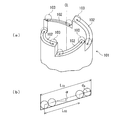
- FIG. 16A is a perspective view showing one of the cam members 101 disclosed in Patent Document 2, and the cam member 101 is provided with four cam surfaces 102 extending spirally in the circumferential direction. ing. A ball 103 is provided for each of these cam surfaces 102. The ball 103 contributes to smooth relative rotation between the cam members and generation of thrust while moving relative to the cam surface 102 along the arrow shown in FIG. 16A and within the range of the circumferential stroke of the arrow. To do.
- the cam mechanism as described above has the following problems. That is, in each cam surface 102, the ball 103 contributes to the generation of thrust while moving relative to the cam surface 102 (rolling), but the movement of the ball 103 is performed as shown in FIG. Regulated near the end of the surface 102.
- the movable stroke L BS of the plurality (n) of balls 103 has a diameter d b of the balls 103 and the total circumferential length of the cam surfaces 102 is L C1. Then, the following equation is obtained.
- the movable stroke L BS of the ball 103 decreases.
- L BS L C1 ⁇ n ⁇ d b
- the relative rotation amount of the two cam members is regulated by the movable stroke L BS of the ball 103, in order to secure the relative axial movement amount of the two cam members, the number of the balls 103 is reduced, or The helical radius of the helical cam surface 102 must be increased, or the inclination angle (inclination angle with respect to the circumferential surface orthogonal to the central axis CL) ⁇ of the helical cam surface 102 must be increased.
- the present invention has been devised in view of such a problem, and can ensure the length of each cam surface without increasing the inclination angle of the cam surface while allowing many balls to be interposed between the cam surfaces.
- a torque cam device for an automatic transmission is a torque cam device for converting a rotational torque transmitted in an automatic transmission into an axial thrust force.
- a drive cam member having a drive cam surface and rotating in response to rotational torque; and an annular first driven cam surface facing the first drive cam surface; and via a ball by the drive cam member
- a driven cam member that is rotationally driven, and each of the first driving cam surface and the first driven cam surface is equally divided into at least two annular perimeters, and in accordance with a cam angle.
- a connecting portion is formed between the equally divided spiral curved surfaces having at least one of the spiral curved surfaces of the first driving cam surface and the first driven cam surface.
- the spiral curved surface is continuous all around A guide groove for guiding the movement of the ball is provided.
- connection portion includes a first connection surface extending in an axial direction from an end portion of one spiral curved surface of the spiral curved surfaces connected to each other by the connection portion, and the first connection surface.
- a second connecting surface that connects the end of the spiral curved surface and the end of the spiral curved surface on the other side of the two spiral curved surfaces, and the second connecting surface is a surface perpendicular to the axial direction. Preferably it is.
- the guide groove includes a spiral groove portion formed in a spiral shape along the one spiral curved surface, and a connection groove portion that is formed between the spiral groove portions and smoothly connects the spiral groove portions.
- a spiral groove portion formed in a spiral shape along the one spiral curved surface
- a connection groove portion that is formed between the spiral groove portions and smoothly connects the spiral groove portions.
- the guide groove includes an opening that allows a part of the ball to protrude from the spiral curved surface, accommodates more than a half of the ball, and the opening width of the opening is: It is preferable that the outer diameter of the ball is smaller.
- the insertion enlarged-diameter portion is formed at a location where the amount of protrusion in the axial direction is less than half of the total amount of protrusion in the spiral curved surface protruding in the axial direction according to the phase angle. .
- the detachment preventing portion is formed by a screw member that is mounted so as to close the enlarged diameter portion of the insertion enlarged diameter portion.
- a second driven cam surface that can contact the first driving cam surface is formed at one end, and a second driving cam surface that can contact the first driven cam surface is formed at the other end, and the drive An intermediate cam member that is rotatable relative to the cam member and the driven cam member; and when the power is transmitted from the driving cam member to the driven cam member, the first driving cam surface and the second driven cam member The cam surface abuts, and when the power is transmitted from the driven cam member to the driving cam member, the first driven cam surface and the second driving cam surface abut to achieve power transmission. It is preferable to be configured.
- the first driving cam surface, the first driven cam surface, the second driven cam surface, and the second driving cam surface all have the spiral curved surface, and the spiral curved surface
- the connecting portions are formed between each other, and the connecting portion of the first driven cam surface and the connecting portion of the second driving cam surface when power is transmitted from the driving cam member to the driven cam member. It is preferable that when the power is transmitted from the driven cam member to the driving cam member, the connecting portion of the first driving cam surface and the connecting portion of the second driven cam surface are in contact.
- This automatic transmission is an automatic transmission provided with a continuously variable transmission mechanism comprising two pulley devices including a fixed pulley and a movable pulley, and a belt wound around the two pulley devices to transmit power.
- a torque cam device that generates a clamping pressure in one of the two pulley devices.
- the driving cam member rotates integrally with the movable pulley
- the driven cam member rotates integrally with the fixed pulley
- the intermediate cam member is mounted so as to be rotatable relative to the rotation shaft of the pulley device.
- each ball can be interposed between the cam surfaces without increasing the inclination angle of the cam surface.
- the length of the cam surface can be secured. For this reason, for example, when used in a thrust generation mechanism of a transmission mechanism of a belt type continuously variable transmission, a large thrust can be generated and a sufficient ratio coverage can be ensured without increasing the size of the device. become able to.
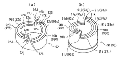
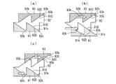
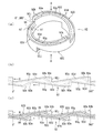
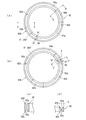
- FIG. 1 It is a perspective view of the cam member of the torque cam apparatus concerning one Embodiment of this invention, (a) shows an intermediate cam member, (b) shows a drive cam member and a to-be-driven cam member. It is a typical peripheral view explaining the operation mode of the torque cam device concerning one embodiment of the present invention, (a) shows the state where each cam member matched the phase, and (b) shows the drive cam member. The state where the phase is advanced is shown, and (c) shows the state where the drive cam member delays the phase. BRIEF DESCRIPTION OF THE DRAWINGS FIG.
- FIG. 1 is a schematic peripheral view for explaining the effect of a torque cam device according to an embodiment of the present invention, wherein (a) to (c) sequentially show a process in which a drive cam member of the torque cam device advances in phase; (D) shows the proportionality.
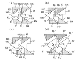
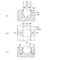
- FIG. 4 is a schematic peripheral view for explaining the effect of the torque cam device according to the embodiment of the present invention, where (a) shows a proportional cam member and (b) shows a cam member of the torque cam device. It is a figure which shows the detailed structure of the cam member of the torque cam apparatus concerning one Embodiment of this invention, (a) is the perspective view, (b) is the expanded view of the outer peripheral surface, (c) is the guide groove of FIG.
- An electric vehicle according to the present embodiment (hereinafter also simply referred to as a vehicle) is an electric vehicle (also referred to as an EV) that travels using only an electric motor as a drive source, and travels selectively using an electric motor and an internal combustion engine as a drive source. Does not include hybrid electric vehicles. Moreover, this automatic transmission is interposed between the electric motor and drive wheel of such a vehicle.
- the drive system unit is a transmission that is integrally connected to a main electric motor (also simply referred to as an electric motor) 1 that is a drive source of a vehicle and an output shaft of the main electric motor 1.
- a main electric motor also simply referred to as an electric motor
- An automatic transmission 2 having an input shaft (hereinafter referred to as an input shaft) 2A, a reduction mechanism 6 connected to the automatic transmission 2, and a differential mechanism 7 connected to the reduction mechanism 6 are provided.
- Drive wheels (not shown) are coupled to the axles 7L and 7R connected to the left and right side gears of the differential mechanism 7, respectively.
- the automatic transmission 2 is obtained by adding a direct gear mechanism 20 to a so-called belt type continuously variable transmission (CVT) with an auxiliary transmission mechanism.
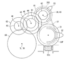
- the automatic transmission 2 includes a belt-type continuously variable transmission mechanism (hereinafter also referred to as a variator) 3 having a belt 37 for power transmission, and a primary pulley (input unit) 30P arranged to be rotatable relative to the input shaft 2A.
- the constant-mesh parallel-shaft gear transmission mechanism (hereinafter also referred to as a sub-transmission mechanism) 4 connected to the rotary shaft 36 of the secondary pulley (output unit) 30S of the variator 3, and the variator 3 and the sub-transmission mechanism 4 are bypassed.
- a direct connection gear mechanism 20 that directly connects the input shaft 2A and the speed reduction mechanism 6 is provided.
- the variator 3 includes a primary pulley 30P including a fixed pulley 31 having a rotation shaft 33 and a movable pulley 32, a secondary pulley 30S including a fixed pulley 34 having a rotation shaft (output shaft) 36 and a movable pulley 35, and a primary pulley.
- a belt 37 wound around a V groove between 30P and the secondary pulley 30S is provided.
- the rotation shaft 33 of the fixed pulley 31 of the primary pulley 30P is disposed so as to be rotatable relative to the input shaft 2A.
- the primary pulley (pulley device) 30P, the secondary pulley (pulley device) 30S, and the belt 37 of the variator 3 are shown in a low-side state and a high-side state, respectively.
- the low side state is shown in the half of each outer side (the side that is separated from each other) of the primary pulley 30P and the secondary pulley 30S
- the high side state is shown in the half part of each inside (the side that is close to each other).
- the belt 37 the low-side state is schematically shown by a solid line
- the high-side state is schematically shown by a two-dot chain line inside the pulleys 30P and 30S.
- the high state indicated by the two-dot chain line only indicates the positional relationship between the pulley and the belt in the radial direction, and the actual belt position does not appear in the inner half of the pulley.
- Adjustment of the gear ratio by changing the belt winding radius of the primary pulley 30P and the secondary pulley 30S of the variator 3 and adjustment of the pulley shaft thrust (also simply referred to as thrust), that is, adjustment of the belt narrow pressure, is performed with the electric actuator 80A. And is executed by a force mechanism.
- a torque cam mechanism is used as the mechanical reaction force mechanism.
- the torque cam mechanism is composed of a pair of annular cam members each having a spirally inclined cam surface at each end, and is arranged coaxially so that the cam surfaces are in sliding contact with each other.
- the pair of cam members are separated from each other in the axial direction, and the total length of the pair of cam members is changed, so that the thrust of the rotating members (pulleys 30P and 30S) pressed against the one cam member is increased. To be adjusted.
- a torque cam mechanism is used as a mechanical reaction force mechanism for both the primary pulley 30P and the secondary pulley 30S.
- the ball torque cam mechanisms of both pulleys act as a reaction force of the force that the belt 37 presses against the primary pulley 30P and the secondary pulley 30S (force that attempts to separate the pulleys), and according to the transmission torque of the belt 37 Thrust is generated in both pulleys 30P and 30S without using hydraulic pressure or the like.
- the primary pulley 30P is equipped with an electric actuator 80A that actively rotates and drives one of the pair of cam members, and adjusts the groove width of the V groove of the primary pulley 30P by changing the total length of the pair of cam members. Configured to do.
- each torque cam mechanism a ball torque cam mechanism in which the sliding contact portion of each cam surface is a point contact via a ball is employed.
- the primary pulley 30P includes a torque cam mechanism that is a mechanical reaction force mechanism and an electric actuator 80A that rotationally drives one of the pair of cam members.
- the gear ratio is adjusted by adjusting the groove width of the groove, and the belt clamping pressure is adjusted by adjusting the thrust of the pulley 30P. Therefore, a mechanism including the electric actuator 80A of the primary pulley 30P and the torque cam mechanism is also referred to as a speed change mechanism 8.
- the torque cam mechanism of the secondary pulley 30S is also referred to as a thrust generating mechanism 9 because it generates the thrust of the secondary pulley 30S. Details of the speed change mechanism 8 and the thrust generation mechanism 9 will be described later.
- the auxiliary transmission mechanism 4 has a plurality of shift stages (here, two stages of high and low), and is mounted on a rotary shaft 43 coaxial with the rotary shaft 36 of the secondary pulley 30S of the variator 3 so as to be relatively rotatable.
- Gears 41 and 42 and gears 44 and 45 fixed so as to rotate integrally with a rotation shaft 46 parallel to the rotation shaft 43 are provided.
- the gear 41 and the gear 44 are always meshed with each other and constitute a second speed (high) gear stage.
- the gear 42 and the gear 45 are always meshed to form a first (low) gear stage.
- the sub-transmission mechanism 4 is equipped with a three-position mesh clutch mechanism 5B for selectively switching between the second gear and the first gear.
- the meshing clutch mechanism 5B includes a clutch hub 54 that rotates integrally with the rotary shaft 43, a sleeve 55 that has internal teeth 55a that are spline-engaged with external teeth 54a that are provided on the clutch hub 54, and a sleeve 55 in a shift direction (axial direction). ) And a switching electric actuator 50 ⁇ / b> B that drives the shift fork 56.
- the gear 41 is provided with external teeth 41a that can mesh with the internal teeth 55a of the sleeve 55
- the gear 42 is provided with external teeth 42a that can mesh with the internal teeth 55a of the sleeve 55.
- the sleeve 55 has a neutral position (N), a second speed position (H) for setting the second (high) gear stage, and a first speed position (L) for setting the first (low) gear stage. Each position is slidably driven by a shift fork 56.
- the direct gear mechanism 20 includes an input gear (input gear) 21 disposed so as to be rotatable relative to the input shaft 2A.
- the input gear 21 is one of a plurality of transmission gears of the auxiliary transmission mechanism.
- gear 45 which is the output side gear of the first gear stage
- the input gear 21 and the gear 45 are set so that the number of teeth is substantially the same and the gear ratio is approximately 1.0.
- a three-position mesh clutch mechanism 5A is provided.
- the meshing clutch mechanism 5 ⁇ / b> A is configured similarly to the meshing clutch mechanism 5 ⁇ / b> B and is spline-engaged with a clutch hub 51 that rotates integrally with the input shaft 2 ⁇ / b> A and an external tooth 51 a provided on the clutch hub 51.
- a sleeve 52 having internal teeth 52a, a shift fork 53 that moves the sleeve 52 in the shift direction (axial direction), and a switching electric actuator 50A that drives the shift fork 53 are provided.
- the input gear 21 is provided with external teeth 22 that can mesh with the internal teeth 52 a of the sleeve 52, and the external teeth that can mesh with the internal teeth 52 a of the sleeve 52 on the rotating shaft 33 of the fixed pulley 31 of the primary pulley 30 ⁇ / b> P in the variator 3. 38 is provided.
- the sleeve 52 includes a neutral position (N), a CVT position (C) for setting a power transmission path via the variator 3, and a direct connection position (D) for setting a power transmission path via the direct connection gear mechanism 20. There are positions, and each position is slid by a shift fork 53.
- the meshing clutch mechanisms 5A and 5B are not equipped with the synchro mechanism.
- the synchro mechanism is provided, an effect of further promoting the synchronization can be obtained.
- a synchro mechanism is essential.
- the speed reduction mechanism 6 is fixedly provided so as to rotate integrally with a rotating shaft 65 parallel to the rotating shaft 46 and meshed with the gear 61 so as to rotate integrally with the rotating shaft 46 of the auxiliary transmission mechanism 4.
- the speed is reduced between the gear 61 and the gear 62 according to the gear ratio, and further, the speed is reduced between the gear 63 and the gear 64 according to the gear ratio.
- Thrust generation mechanism mechanical reaction force mechanism
- the thrust generating mechanism 9 which is one of the mechanical reaction force mechanisms and is provided in the secondary pulley 30S will be described.
- the thrust generating mechanism 9 employs a torque cam mechanism.
- a torque cam mechanism (torque cam device) 90 employed here will be described with reference to FIGS.
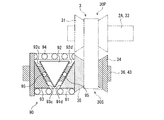
- the torque cam mechanism 90 is an end face cam and is adjacent to the drive cam member 91 (drive cam member) 91 fixed to the back surface of the movable pulley 35 and the drive cam member 91.
- the driven cam member (driven cam member) 93 fixed to the rotation shaft 36 of the fixed pulley 34 and the drive cam member 91 and the driven cam member 93 are coaxially disposed.
- three cam members including an intermediate cam member 92 capable of relative rotation are provided.
- the drive cam member 91 drives the driven cam member 93 when the vehicle is driven (driving), and the driven cam member 93 drives the drive cam member 91 when the vehicle is coasted (driven).
- the torque cam mechanism 90 is comprised from three cam members, the intermediate cam member 92 is not essential for the torque cam mechanism 90, and the intermediate cam member 92 is not provided as this invention. It can also be applied to a torque cam mechanism.
- the drive cam member 91 is a cylindrical (or annular) member having an annular first drive cam surface 91D on one end side, and the other end. The side is fixed to the back surface of the movable pulley 35.
- the annular first drive cam surface 91D is equally divided into two annular entire circumferences, and each first drive cam surface 91D has a spiral curved surface 91d corresponding to a predetermined cam angle.
- Connection portions 91J are formed between two equally divided first drive cam surfaces 91D.
- the connecting portion 91J is formed in a step shape from the end of the spiral curved surface 91d on one side and extends in the axial direction (first connecting surface) 91j, and the end of the connecting surface 91j and the spiral on the other side.
- a second connecting surface 91k that connects the end of the curved surface 91d.
- Each connection surface 91j is formed in an axial direction (direction parallel to the rotational axis) along the rotational axis of the drive cam member 91, and the second connecting surface 91k is a surface perpendicular to the axial direction.
- the driven cam member 93 has a shape symmetrical to the driving cam member 91, and is a shape obtained by inverting the perspective view of FIG. 6B will be described.
- the first driven cam surface 93 ⁇ / b> C having an annular shape is provided on one end side, and the other end side is fixed to the rotary shaft 36.
- the annular first driven cam surface 93C is equally divided into two annular entire circumferences, and each first driven cam surface 93C has a spiral curved surface 93c corresponding to a predetermined cam angle. .
- Connection portions 93J are formed between the two equally divided first driven cam surfaces 93C.
- connection portion 93J is formed in a step shape from the end portion of the spiral curved surface 93c on one side and extends in the axial direction (first connection surface) 93j, and the end portion of the connection surface 93j and the spiral shape on the other side.
- a second connecting surface 93k that connects the end of the curved surface 93c.
- Each of the connection surfaces 93j is formed in an axial direction along the rotational axis of the driven cam member 93 (a direction parallel to the rotational axis).
- the connection surfaces 93j are also formed in the axial direction of the driven cam member 93, and the second connecting surface 93k is a surface perpendicular to the axial direction.
- the intermediate cam member 92 is a cylindrical (or annular) member, and has an annular shape opposite to the first drive cam surface 91D of the drive cam member 91 on one end side.
- a second driven cam surface 92D is provided, and an annular second driving cam surface 92C facing the first driven cam surface 93C of the driven cam member 93 is provided on the other end side.
- the intermediate cam member 92 functions as a driven cam member for the driving cam member 91, and functions as a driving cam member for the driven cam member 93.
- the annular second driven cam surface 92D is equally divided into two annular entire peripheries, each having a spiral curved surface 92d corresponding to a predetermined cam angle.
- Connection portions 92J are respectively formed between the two equally divided first drive cam surfaces 92D.
- the connection portion 92J is formed in a step shape from the end portion of the spiral curved surface 92d on one side and extends in the axial direction (first connection surface) 92j, and the end portion of the connection surface 92j and the spiral shape on the other side.
- a second connecting surface 92k that connects the end of the curved surface 92d.
- the connection surfaces 92j are also formed in the axial direction of the intermediate cam member 92, and the second connecting surface 92k is a surface perpendicular to the axial direction.
- the annular second driving cam surface 92C has a shape symmetrical to the second driven cam surface 92D, and is a shape obtained by inverting the perspective view of FIG.
- the second drive cam surface 92C is also divided into two equal parts on the entire circumference of the ring, and each has a spiral curved surface 92c corresponding to a predetermined cam angle.
- Connection portions 92J are formed between the two equally divided first driven cam surfaces 92C.
- the connecting portion 92J is formed in a step shape from the end of the spiral curved surface 92d on one side and extends in the axial direction, and the end of the first connecting surface 92j and the spiral curved surface 92d on the other side.
- a second connection surface 92k that connects the end portions of the second connection surface 92k.
- the first connecting surface connecting surface 92j is also formed in the axial direction of the intermediate cam member 92, and the second connecting surface 92k is a surface perpendicular to the axial direction.
- the second driven cam surface 92D and the second driving cam surface 92C of the intermediate cam member 92 are formed with a phase shift in the rotational direction.
- the first connecting surface 92j that connects the two second driven cam surfaces 92D and the first connecting surface 92j that connects the two second driving cam surfaces 92C are disposed and formed out of phase in the rotational direction. ing.
- the phase shift between the cam surfaces 92D and 92C can be 90 degrees at the maximum. Thereby, the axial direction length of the intermediate cam member 92 can be shortened.
- the second driven cam surface 92D of the intermediate cam member 92 can contact the first driving cam surface 91D of the driving cam member 91, and the second driving cam surface 92C of the intermediate cam member 92 is in contact with the driven cam member 93.
- the first driven cam surface 93C can be contacted.
- a ball (steel ball) 95 is interposed between the drive cam surfaces 91D and 92D and between the driven cam surfaces 93C and 92C, and the torque cam mechanism 90 is configured as a ball torque cam device.
- the first driving cam surface 91D of the driving cam member 91, the second driven cam surface 92D and the second driving cam surface 92C of the intermediate cam member 92 On the spiral curved surface or the like of the first driven cam surface 93C of the driving cam member 93, grooves (guide grooves) 91g, 92G, and 93g having arcuate cross-sections that interpose the balls 95 are formed.
- the drive cam surfaces 91D and 92C and the driven cam surfaces 93D and 92C slide smoothly by point contact with the balls 95.
- the grooves 92G of the second driven cam surface 92D and the second driving cam surface 92C of the intermediate cam member 92 are configured as guide grooves (deep grooves) that accommodate more than half of the balls 95.
- the grooves 91g, 93g of the first driving cam surface 91D of the driving cam member 91 and the first driven cam surface 93C of the driven cam member 93 are projected from the balls 95 accommodated in the respective grooves 92G. It is configured as a shallow groove (here, the cross section is a partial arc shape) with which the top portion is in sliding contact.
- the groove 92G of the intermediate cam member 92 is formed in a spiral shape along the spiral driven curved surfaces 92d and 92c of the second driven cam surface 92D and the second drive cam surface 92C of the intermediate cam member 92.
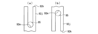
- a connecting groove portion 92m that is formed between the helical groove portions 92g and smoothly connects the helical groove portions 92g.
- the connection groove portion 92m is formed in a partial spiral shape that is inclined in the circumferential direction opposite to the spiral groove portion 92g, and is connected to the spiral groove portion 92g with a smooth curved surface. Therefore, the groove 92G is configured to be continuous over the entire circumference by the spiral groove 92g and the connection groove 92m, and smoothly guides the movement of the ball 95 over the entire circumference.
- a plurality of balls 95 are mounted so as to be able to roll while being in sliding contact with each other in series. Accordingly, even when the driving direction of the torque between the driving cam member 91 and the driven cam member 93 is switched, that is, when the driving of the cam members 91 and 93 is switched, as in coasting, the groove is also changed.
- the ball 95 inside the 92G is not easily affected by this replacement. Lubricating oil is supplied to the inside of the groove 92G, and each ball 95 rolls very smoothly inside the groove 92G.
- the groove 92G is formed in a partial circle shape whose cross section is wider than a semicircle, and holds the ball 95 and regulates the detachment of the ball 95. That is, as shown in FIG. 13, the groove 92G includes an opening 98 that allows a part of the ball 95 to protrude from the spiral curved surface 92d in the spiral groove 92g, and a half of the ball 95 (lower in FIG. 13). Accommodates more than half).
- overhang portions 98a and 98a facing each other are formed at both edges of the opening 98, and the open width w of the opening 98 is between the overhang portions 98a and 98a. It is formed smaller than. As a result, the ball 95 is held and the separation of the ball 95 is restricted.
- the cross section of the spiral groove 92g is formed in a partial circular shape having an inner diameter slightly larger than the outer diameter d of the ball 95.
- an insertion enlarged diameter portion 96 having a diameter larger than the outer diameter d of the ball 95 is formed in a part of the opening 98.
- the ball 9 can be loaded into the groove 92 ⁇ / b> G from the insertion enlarged diameter portion 96.
- a separation preventing portion for preventing separation of the ball 95 after loading from the inside of the groove 92G is formed.
- the separation preventing portion of the present embodiment is formed by a screw member 99 that is mounted so as to close the enlarged diameter portion of the insertion enlarged diameter portion 96. That is, when the screw holes 97 are machined on both sides of the expanded diameter portion 96 for insertion and all the balls 95 are loaded, the screw members 99 are fastened to the respective screw holes 97.
- the head of the screw member 99 is formed with a portion having the same shape as that of the overhang portion 98a. After the screw member 99 is fastened, the cross section of the expanded diameter portion 96 is similar to the overhang portions 98a and 98a.
- the cross-sectional shape prevents the ball 95 after loading from being detached from the interior 92G and does not prevent the ball 95 from rolling smoothly in the groove 92G.
- the separation preventing portion is not limited to the screw member 99.
- the cam surface 92d is built up outward (upward in FIG. 13A) in the insertion enlarged diameter portion 96, and the ball 95 When all of the above are loaded, it is conceivable to form a portion having the same shape as the overhang portion 98a by caulking this portion from the outside.
- the insertion enlarged-diameter portion 96 is formed at a location where the protruding amount in the axial direction is less than half of the spiral curved surface 92d. That is, the helically curved surface 92d protrudes in the axial direction according to the phase angle.
- a portion where the protruding amount in the axial direction is half or less of the total protruding amount is a valley side of the spirally curved surface 92d, and the protruding amount is the total protruding amount.
- the portion larger than half can also be referred to as the crest side of the spiral curved surface 92d, but the insertion enlarged diameter portion 96 is formed on the trough side (see FIG. 10).
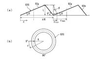
- FIG. 14A is a developed view schematically showing the inclined state of the groove 92G
- FIG. 14B is a plan view of the groove 92G.
- the cam angle ⁇ shown in FIG. 14 (a) assumes that all of the helical groove 92g of the groove 92G contributes to the stroke of the cam mechanism, and the cam groove center radius is R (see FIG. 14 (b)). If the required stroke of the cam mechanism is L and the circulating cam return angle of the connecting groove 92m shown in FIG. 14A is ⁇ ′, it can be expressed by the following equation.
- the length about three times the physical lower limit value ⁇ min is set as a practical lower limit value (lower limit value for preventing tool interference) ⁇ minr , but the lower limit value for preventing tool interference.
- ⁇ minr is not limited to this, for example, set by adding a predetermined amount based on the insertion region of the tool to the physical lower limit value ⁇ min .
- the operation mechanism of the torque cam mechanism 90 will be described in detail. If the driving cam member 91 and the driven cam member 93 are not out of phase, as shown in FIG. 7A, the first driving cam surface 91D of the driving cam member 91 and the second driven cam member 92 are driven.
- the drive cam surface 92 ⁇ / b> D is engaged with the first driven cam surface 93 ⁇ / b> C of the driven cam member 93 and the second drive cam surface 92 ⁇ / b> C of the intermediate cam member 92 is engaged with the drive cam member 91 and the intermediate cam member 92.
- the driven cam member 93 that is, the total length of the torque cam mechanism 90 is minimized.
- the groove width of the V groove of the secondary pulley 30S is maximized, and the gear ratio of the variator 3 is maximized.
- the drive cam member 91 fixed to the movable pulley 35 is slid between the drive cam surface 91D and the driven cam surface 92D via the ball 95, and as shown in FIG. While rotating relatively ahead of the driven cam member 93 fixed to the member 92 and the fixed pulley 34, it moves away from the driven cam member 93 and the intermediate cam member 92 in the axial direction.
- the movable pulley 35 is brought close to the fixed pulley 34.
- the groove width of the V groove of the secondary pulley 30S is narrowed and the thrust of the pulley 30S is increased, so that the belt clamping pressure is increased and the slip of the fixed pulley 34 is eliminated.
- the rotational phase delay of the fixed pulley 34 is eliminated, and the belt of the secondary pulley 30S is clamped against the negative input torque.
- the fixed pulley 34 advances the rotational phase relative to the movable pulley 35 (in other words, the movable pulley 35 causes a rotational phase delay relative to the fixed pulley 34).
- the driven cam member 93 fixed to the fixed pulley 34 slides between the driven cam surface 93 ⁇ / b> C and the driving cam surface 92 ⁇ / b> C via the balls 95, as shown in FIG. 7C. It moves relative to the drive cam member 91 and the intermediate cam member 92 so as to be separated from each other in the axial direction while rotating relative to the cam member 92 and the movable cam member 91 fixed to the movable pulley 35. Pull the pulley 35 close to the fixed pulley 34. As a result, the groove width of the V groove of the secondary pulley 30S is narrowed and the thrust of the pulley 30S is increased, so that the belt clamping pressure is increased and the slip of the fixed pulley 34 is eliminated.
- a coil spring 94 that urges the movable pulley 35 in a direction approaching the fixed pulley 34 so that the belt 37 can be reliably clamped even during initial driving such as when the vehicle is started. Is equipped.
- the speed change mechanism 8 provided in the primary pulley 30P includes an electric actuator 80A and a mechanical reaction force mechanism 80B.
- a torque cam mechanism is adopted as the mechanical reaction force mechanism 80B.
- the torque cam mechanism employed in the mechanical reaction force mechanism 80B has a pair of cam members 83 and 84 disposed on the back of the movable pulley 32 of the primary pulley 30P and coaxially disposed on the rotation shaft 33.
- the cam members 83 and 84 are respectively formed with spiral cam surfaces 83a and 84a that are inclined with respect to the direction orthogonal to the rotation shaft 33, and the pair of cam members 83 and 84 have their respective cam surfaces.
- 83a and 84a are arranged in contact with each other.
- a ball torque cam mechanism in which a ball (steel ball) 85 is interposed between the cam surfaces 83a and 84a that are in sliding contact and the sliding contact portion is point-contacted by the ball 85 is employed.
- 83a and 84a slide smoothly.
- Both the cam member 83 and the cam member 84 can rotate relative to the rotary shaft 33, and are arranged coaxially with the rotary shaft 33 independently of the fixed pulley 31 and the movable pulley 32 of the primary pulley 30P. That is, the cam members 83 and 84 do not rotate even when the primary pulley 30P rotates.
- the cam member 84 is a fixed cam member that is fixed both in the rotational direction and in the axial direction, whereas the cam member 83 is rotatable relative to the cam member 84 and is also movable in the axial direction. It is a movable cam member.
- the movable cam member 83 is provided with a sliding contact surface 83b that is in sliding contact with the back surface 32a of the movable pulley 32 via a thrust bearing or the like on the opposite side to the cam surface 83a.
- the electric actuator 80A rotates the movable cam member 83 to rotate the cam surface 83a of the movable cam member 83 with respect to the cam surface 84a of the fixed cam member 84, so that the cam surface 83a and the cam surface 84a are inclined. Then, the movable cam member 83 is moved in the axial direction of the rotary shaft 33, the movable pulley 32 is moved in the axial direction of the rotary shaft 33, and the groove width of the V groove of the primary pulley 30P is adjusted.
- the electric actuator 80A includes a worm gear mechanism 82 including a worm (screw gear) 82a and a worm wheel (helical gear) 82b that meshes with the worm 82a, and an electric motor 81 that rotationally drives the worm 82a.
- the worm wheel 82b is arranged coaxially with the rotary shaft 33, and is serrated and coupled to the outer periphery of the movable cam member 83 so as to rotate integrally with the movable cam member 83 and allow the movable cam member 83 to move in the axial direction. ing.
- the electric motor 81 is operated to drive the worm 82a to rotate, the worm wheel 82b rotates to rotate the movable cam member 83 and adjust the groove width of the V groove of the primary pulley 30P.
- the groove width adjustment of the primary pulley 30P by the transmission mechanism 8 is performed while receiving the thrust of the secondary pulley 30S generated by the thrust generating mechanism 9.
- the groove width of the V-groove of the primary pulley 30P When narrowing the groove width of the V-groove of the primary pulley 30P, the groove width of the V-groove of the secondary pulley 30S connected via the belt is increased, and the thrust generated by the thrust generating mechanism 9 is opposed.
- the groove width of the V groove of the primary pulley 30P is increased, the groove width of the V groove of the secondary pulley 30S is reduced, and the thrust generated by the thrust generating mechanism 9 is used.
- the electric motor 81 when narrowing the groove width of the V groove of the primary pulley 30P, the electric motor 81 is operated to separate the movable cam member 83 from the fixed cam member 84. In response to this, the winding radius of the belt 37 around the primary pulley 30P increases and the tension of the belt 37 increases. The increase in the tension of the belt 37 acts to reduce the winding radius of the belt 37 around the secondary pulley 30S. In order to reduce the winding radius of the belt 37 around the secondary pulley 30S, it is necessary to increase the groove width of the V groove of the secondary pulley 30S, and the thrust generation mechanism 9 of the secondary pulley 30S counters this increase in groove width. Effectiveness occurs as a thrust. Therefore, the electric actuator 80A drives the movable cam member 83 against this thrust.
- the electric motor 81 is operated to bring the movable cam member 83 closer to the fixed cam member 84.
- the winding radius of the belt 37 around the primary pulley 30P decreases, and the tension of the belt 37 decreases.
- the decrease in the tension of the belt 37 causes the secondary pulley 30S and the belt 37 to slip, and the movable pulley 35 of the secondary pulley 30S follows the belt 37, but the fixed pulley 34 causes the belt 37 to slip.
- the fixed pulley 34 and the movable pulley 35 are twisted.
- the thrust of the secondary pulley 30 ⁇ / b> S is enhanced according to the twist of the fixed pulley 34 and the movable pulley 35.
- the variator 3 of the automatic transmission 2 is provided with an auxiliary electric motor 10 that is directly connected to the rotary shaft 33 of the primary pulley 30P.
- the auxiliary electric motor 10 drives the rotation shaft 33 during the switching operation by the meshing clutch mechanism 5A so as to promote rotation synchronization between the input side and the output side of any gear stage of the auxiliary transmission mechanism 4. Equipped to.
- the vehicle includes an EV ECU 110 that controls the electric vehicle in total and a CVT ECU 100 that controls a main part of the automatic transmission (CVT with an auxiliary transmission mechanism) 2.
- Each ECU is a computer composed of a memory (ROM, RAM) and a CPU.
- the CVT ECU 100 operates the electric motor 81, the switching electric actuators 50A and 50B, the auxiliary electric motor 10 and the like constituting the electric actuator 80A of the speed change mechanism 8 based on commands or information from the EV ECU 110 or information from other sensors. Control.
- the automatic transmission 2 is configured by adding a sub-transmission mechanism (always meshing parallel shaft gear transmission mechanism) 4 and a direct-coupled gear mechanism 20 to a variator (belt-type continuously variable transmission sub-transmission mechanism) 3.
- a sub-transmission mechanism always meshing parallel shaft gear transmission mechanism
- a direct-coupled gear mechanism 20 to a variator (belt-type continuously variable transmission sub-transmission mechanism) 3.
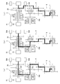
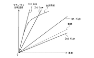
- the CVTECU 100 can select and use three power transmission modes roughly as shown in FIG. 3 using a shift map as shown in FIG.
- the CVT low mode is selected in which the variator 3 is used and the subtransmission mechanism 4 is set to the first speed (low).
- the CVT high mode is selected in which the variator 3 is used and the auxiliary transmission mechanism 4 is set to the second speed (high).
- this CVT high mode can deal with many driving modes.
- the variator 3 can be driven in a wide speed ratio range up to the highest state (2nd High).
- the load on the electric motor 1 of the drive source can be reduced, the power train can be made compact by reducing the size of the electric motor 1, and the electric motor 1 can be used in an efficient area. Powertrain efficiency can be improved and the cruising range of an electric vehicle can be increased.
- a direct gear mechanism 20 is used as shown in FIG.
- power transmission by a gear having high transmission efficiency can be realized, and also from this point, the electric cost can be improved, and the cruising distance of the electric vehicle can be increased.
- the gear ratio by the direct-coupled gear mechanism 20 is set slightly higher than the gear ratio of the second speed and the lowest speed, the burden on the motor 1 during high speed running can be reduced and the continuity of the electric vehicle can be reduced. It also contributes to an increase in distance.
- the rotation synchronization is promoted, the shift time can be shortened, and the shift shock can be reduced. Is possible.
- synchronization adjustment can be performed accurately, and the cost of the apparatus can be reduced by omitting the synchro mechanism and the like.
- the rotation of the rotation shaft 43 of the auxiliary transmission mechanism 4 is synchronized with the rotation of the gear 41 or the gear 42.
- the large inertial mass of the variator 3 can be overcome and synchronization can be obtained quickly, and the shift time can be shortened.
- the mesh clutch mechanism 5A switches between the state in which the variator 3 is used and the state in which the direct connection gear mechanism 20 is used, the input rotary member and the output rotary member in the mesh clutch mechanism 5A are rotationally synchronized.
- the electric motor 1 and the auxiliary electric motor 10 can be used.
- the switching can be quickly performed by the following procedure.
- the meshing clutch mechanisms 5A and 5B are both neutral.
- the auxiliary electric motor 10 promotes the rotation synchronization between the rotation shaft 43 of the auxiliary transmission mechanism 4 and the gear (gear 41 or gear 42) corresponding to the speed to be achieved via the variator 3
- Control is performed so that the rotation of an electric motor 1 is synchronized with the rotation of the rotation shaft 33 of the input section (primary pulley) 30P of the variator 3.
- the meshing clutch mechanism 5A in the neutral state is engaged with the member on the input shaft 2A side (the inner teeth 52a of the sleeve 52) and the input rotating member (the outer teeth 38 of the rotating shaft 33) of the primary pulley 30P of the variator 3.
- the meshing clutch mechanism 5B in the neutral state is switched to be connected to the gear (gear 41 or gear 42) corresponding to the speed stage to be achieved.
- the mesh clutch mechanisms 5A and 5B can be switched in a short time, and it becomes difficult to give a feeling of torque loss, so that the drive feeling for shifting can be improved.
- auxiliary electric motor 10 in this embodiment is only used for rotation synchronization at the time of shifting, a small motor with a small output can be adopted, and an increase in cost of the apparatus can be suppressed.
- auxiliary electric motor 10 is connected, a small motor with low output corresponding to low torque can be easily adopted. It is also conceivable to use the output of the auxiliary electric motor 10 as torque assist for driving the vehicle. In this case, the auxiliary electric motor 10 has a corresponding output.
- the both meshing clutch mechanisms 5A and 5B are set to neutral. Then, control is performed so that the rotation of the electric motor 1 is synchronized with the rotation of the input gear 21.
- the meshing clutch mechanism 5A in the neutral state is directly connected to the input shaft 2A side member (inner teeth 52a of the sleeve 52) and the input gear 21 side member (external teeth 52a). ).
- the meshing clutch mechanism 5B maintains neutral during direct drive.
- torque cam mechanism (torque cam device) 90 the following operations and effects can be obtained.
- driving that is, when power is transmitted from the driving cam member 91 to the driven cam member 93
- coasting that is, when power is transmitted from the driven cam member 93 to the driving cam member 91
- the first driven cam surface 93C of the driven cam member 93 and the second driving cam surface 92C of the intermediate cam member 92 abut.
- the first driving cam surface 91D, the second driven cam surface 92D, the first driven cam surface 93C, and the second driving cam surface 92C, both of which are annular, can be formed over the entire circumference of the annular, The length of the cam surface can be secured by the circumference.
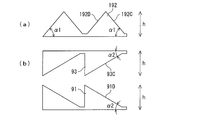
- FIG. 9A is a schematic peripheral view when a torque cam device is configured without using an intermediate cam.
- the driving cam surface 192D and the driven cam surface 192c are annular.
- the length of the cam surface can be secured only by half of the entire circumference.
- FIG. 9B is a schematic circumferential view in the case where the height difference (corresponding to the cam stroke) of the cam surface of the torque cam mechanism 90 is set the same as that in FIG. 9A.
- the cam surfaces 91D and 93C also cam surfaces 92D and 92C not shown
- the cam surface inclination angle ⁇ 2 can be made smaller than the inclination angle ⁇ 1 without using the intermediate cam ( ⁇ 2 ⁇ 1), and the generated thrust can be increased while securing the cam stroke amount.
- connection surfaces 91j, 92j, 93j is formed in a direction along the rotation axis (a direction parallel to the rotation axis), the torque cam mechanism 90 operates quickly. That is, when the torque cam mechanism 90 is driven, as shown in FIG. 8A, power is transmitted from the drive cam member 91 to the driven cam member 93, and the first drive cam surface of the drive cam member 91 is driven. 91D presses the second driven cam surface 92D of the intermediate cam member 92 (see arrow F1), and the connection surface 92j of the intermediate cam member 92 abuts on the connection surface 93j of the driven cam member 93.
- connection surfaces 92j and 93j are formed in the direction along the rotation axis, respectively, the component force F2 acts on the second driven cam surface 92D in the rotation axis direction along the connection surfaces 92j and 93j.
- the intermediate cam member 92 is pushed toward the driven cam member 93 so that the second driving cam surface 92C of the intermediate cam member 92 becomes the first driven member of the driven cam member 93. It contacts the drive cam surface 93C.
- the first drive cam surface 91 ⁇ / b> D of the drive cam member 91 is connected to the intermediate cam member 92 as shown in FIG. 8C. Slide along the second driven cam surface 92D to generate a thrust F3. In this way, the torque cam mechanism 90 operates quickly.
- the second driven cam surface 92D and the second driving cam surface 92C of the intermediate cam member 92 are formed so as to be out of phase in the rotational direction, positional interference between the cam surfaces 92D and 92C is avoided.
- the axial length of the intermediate cam member 92 can be suppressed. In the present embodiment, since the phase shift between the cam surfaces 92D and 92C is 90 degrees, the axial length of the intermediate cam member 92 is minimized.
- the second driven cam surface 92D and the second driving cam surface 92C of the intermediate cam member 92 are provided with guide grooves 92G for continuously guiding the movement of the ball 95 over the entire circumference. Therefore, it is possible to ensure the length of each cam surface without increasing the inclination angle of the cam surface, while allowing many balls 95 to be interposed between the cam surfaces. For this reason, the load burden of each ball
- the guide groove 92G includes a spiral groove 92g formed in a spiral shape along the spiral curved surface 92d and a connection groove 92m formed between the spiral grooves 92g and smoothly connecting the spiral groove 92g.
- connecting portions 91J, 92J, and 93J are formed between the spiral curved surfaces 91d, 92d, 92c, and 93c that are equally divided among the cam surfaces 91D, 92D, 92C, and 93C.
- the connecting portions 91J, 92J, and 93J include first connecting surfaces 91j, 92j, and 93j extending in the axial direction from the ends of the spiral curved surfaces on one side of the spiral curved surfaces that are connected to each other.
- connection surface 91j, 92j, 93j is provided with the 2nd connection surface 91k, 92k, 93k which connects the edge part of the other side, and the edge part of the spiral surface of the other side, This 2nd connection surface 91k, 92k, 93k is provided.
- the surface is perpendicular to the axial direction, there is an advantage that the axial directions of the drive cam member 91, the intermediate cam member 92, and the driven cam member 93 can be shortened.
- the guide groove 92G includes an opening 98, and a part of the ball 95 protrudes outward from the opening 98 to accommodate more than half of the ball 95.
- the opening width of the opening 98 is Since the ball 95 is formed smaller than the outer diameter, the ball 95 is securely held in the guide groove 92G without being detached from the guide groove 92G.
- a part of the opening 98 of the guide groove 92G is formed with an enlarged diameter portion 96 for insertion so that the ball 95 is inserted into the guide groove 92G. Since the screw member 97 as a separation preventing portion for preventing the ball 95 from being detached from the guide groove is mounted so as to close the enlarged portion of the insertion enlarged portion 96, the ball 95 is inserted into the insertion enlarged portion. Without being separated from the portion 96, it is securely held in the guide groove 92G.
- the insertion enlarged diameter portion 96 is provided in the valley within the above-mentioned range of the angle ⁇ , particularly below the half of the slope of the cam. Since the ball 95 is in multipoint contact, the cam members 91, 92, and 93 can slide along the spiral curved surface accurately. For example, as in the case of one-point contact, it is possible to prevent the cam members 91, 92, 93 from being inclined with respect to the axial direction and to concentrate stress on the peripheral members, thereby improving durability.
- the torque cam mechanism 90 is composed of three cam members 91, 92, 93.
- the intermediate cam member 92 is not essential for the torque cam mechanism 90 and is shown in FIG.
- the present invention can also be applied to a torque cam mechanism that does not include the intermediate cam member 92.
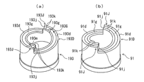
- the torque cam mechanism 90 includes a drive cam member (drive cam member) 91 fixed on the back surface of the movable pulley 35, and a rotating shaft 36 of the fixed pulley 34 adjacent to the drive cam member 91. It is comprised from two cam members with the driven cam member (driven cam member) 193 fixed.
- the driving cam member 91 drives the driven cam member 193 when the vehicle is driving (driving), and the driven cam member 193 drives the driving cam member 91 when the vehicle is coasting (driven). .
- the drive cam member 91 is the same as that of the first embodiment, and the description thereof is omitted [see FIG. 6B].
- the driven cam member 193 has a substantially symmetric shape with the driving cam member 91, has an annular driven cam surface 193D on one end side, and the other end side is a rotating shaft. 36 is fixed.
- the annular driven cam surface 193D is equally divided into two annular entire circumferences, and each driven cam surface 193D has a spiral curved surface 193d corresponding to a predetermined cam angle.
- Connection portions 193J are formed between the two equally divided cam surfaces 193D.
- the connection portion 193J is formed in a step shape from the end portion of the spiral curved surface 193d on one side and extends in the axial direction (first connection surface) 193j, and the end portion of the connection surface 193j and the spiral shape on the other side.
- connection surface 193k that connects the end of the curved surface 193d.
- Each connection surface 193j is formed in an axial direction (a direction parallel to the rotational axis) along the rotational axis of the driven cam member 193.
- the connection surfaces 193j are also formed in the axial direction of the driven cam member 193, and the second connecting surface 193k is a surface perpendicular to the axial direction.
- the driven cam surface 193D of the driven cam member 193 can contact the first driving cam surface 91D of the driving cam member 91.
- a ball (steel ball) 95 is interposed between the drive cam surfaces 91D and 193D, and the torque cam mechanism 90 is configured as a ball torque cam device.
- the ball 95 is guided on the spiral curved surface of the driving cam surface 91D of the driving cam member 91 and the driven cam surface 193D of the driven cam member 193.
- the grooves (guide grooves) 91g and 193G having an arcuate cross section are formed.
- the driving cam surface 91D and the driven cam surface 193D slide smoothly by point contact with the balls 95.
- the guide groove 193G of the driven cam surface 193D of the driven cam member 193 of the present modification is similar to the guide groove 92G of the second driven cam surface 92D of the intermediate cam member 92 of the embodiment, and the spiral groove portion 193g. And a connecting groove 193m.
- the guide groove 193G has an opening (not shown) and protrudes a part of the ball 95 outward from the opening to accommodate more than the half of the ball 95.
- the opening width of the opening is formed smaller than the outer diameter of the ball 95.
- an insertion enlarged diameter portion (not shown) whose diameter is increased to insert the ball 95 into the guide groove 193G is formed in a part of the opening portion of the guide groove 193G.
- a detachment preventing portion (for example, a screw member 97) that prevents the ball 95 from detaching from the inside of the guide groove is provided.
- the diameter-increasing portion for insertion is provided in the valley within the range of the above-mentioned angle ⁇ , and particularly below half of the slope of the cam.
- a guide groove larger than a semicircle for holding the ball 95 may be provided on the drive cam member 91 side.
- the ball 95 interposed between the first drive cam surface 91D of the drive cam member 91 and the second driven cam surface 92D of the intermediate cam member 92 is continuously provided over the entire circumference.
- Guide grooves 91g and 93G are provided, and among these, the guide groove 93G of the second driven cam surface 92D of the intermediate cam member 92 is a guide groove that accommodates more than half of the ball 95.
- the guide groove 91g of the first drive cam surface 91D may be configured as a guide groove that accommodates more than half of the ball 95.
- 92G and 93G are provided, and among these, the guide groove 92G of the second drive cam surface 92D of the intermediate cam member 92 is a guide groove that accommodates more than half of the ball 95, but the first driven cam surface 93C
- the guide groove 93g may be configured as a guide groove that accommodates more than half of the ball 95.
- Grooves 91g and 93G are provided, and among these, the guide groove 93G of the driven cam surface 93C of the driven cam member 93 is a guide groove that accommodates more than half of the ball 95, but the drive cam surface 91D
- the guide groove 91g may be configured as a guide groove that accommodates more than half of the ball 95.
- the processing of the guide groove that accommodates more than the half of the ball 95 is a process that requires a special tool
- the half of the ball 95 is attached to both ends of the intermediate cam member 92 as in the first embodiment.
- the process can be performed efficiently.
- the mesh clutch mechanisms 5A and 5B employ a three-position type to simplify the device configuration.
- a two-position type mesh clutch mechanism is provided for either or both of them. Two can also be used in combination.
- pulley devices 30P and 30S to which the torque cam device 90 is applied can be widely applied not only to the above-described electric vehicles but also to hybrid electric vehicles and engine-driven vehicles.
- the mechanical reaction force mechanism is not limited to the end face cam mechanism shown in the embodiment, but in the case of the end face cam mechanism, a mechanism having a large torque capacity can be configured compactly.
- the meshing location of the meshing clutch mechanisms 5A and 5B is not equipped with a synchro mechanism, but if the gearing location is equipped with a synchro mechanism, high accuracy is not required for the rotation synchronization control.
- the clutch mechanisms 5A and 5B can be engaged with each other before the rotation synchronization is completed, and the time required for shifting can be shortened.
- the ball 95 is prevented from being separated by the guide groove 193G.
- the ball is placed between the cam surfaces separately from the driving cam member and the driven cam member. You may make it provide the holder
Landscapes
- Engineering & Computer Science (AREA)
- General Engineering & Computer Science (AREA)
- Mechanical Engineering (AREA)
- Transmissions By Endless Flexible Members (AREA)
- Transmission Devices (AREA)
Abstract
Description
このようなカム機構は、2つのカム部材の回転位相差に応じて推力を発生させるもので、各カム部材には、回転軸と直交する環状面に対して軸方向へ傾斜したカム面がそれぞれ形成され、カム面の相互間にボール(転動体)が介装され、2つのカム部材に回転位相差を与えることにより、各カム面がボールを介して互いに摺動しながら2つのカム部材が離接してその全長(軸方向長)が変化すると共に、回転軸方向への力(推力)を発生する。
つまり、各カム面102において、ボール103は、カム面102に沿って相対動(転動)しながら推力発生に寄与するが、ボール103の移動は、図16(b)に示すように、カム面102の端部付近で規制される。各カム面102に複数のボール103が装備されると、複数(n個)のボール103の移動可能ストロークLBSは、このボール103の直径をdb、カム面102の周方向全長をLC1とすると、次式のようになり、ボールの数を増やすとボール103の移動可能ストロークLBSは減少する。
LBS=LC1-n×db
したがって、2つのカム部材の相対的な軸方向移動量を確保することが困難になり、ベルト式無段変速機の可動プーリに適用すると、可動プーリの軸方向移動ストロークを十分に確保できず、延いては、自動変速機のレシオカバレッジを十分に確保することができなくなるという課題がある。
まず、車両の駆動系ユニットを説明する。図1及び図2に示すように、この駆動系ユニットは、車両の駆動源である主電動モータ(単に、電動モータとも言う)1と、主電動モータ1の出力軸と一体連結された変速機入力軸(以下、入力軸という)2Aを有する自動変速機2と、自動変速機2に接続された減速機構6と、減速機構6に接続された差動機構7と、を備えている。差動機構7の左右のサイドギヤに接続された車軸7L,7Rには、図示しない駆動輪がそれぞれ結合されている。
スリーブ55は、ニュートラルポジション(N)と、2速(ハイ)ギヤ段を設定する2速ポジション(H)と、1速(ロー)ギヤ段を設定する1速ポジション(L)との各ポジションを有し、各ポジション間を、シフトフォーク56によってスライド駆動される。
直結ギヤ機構20は、入力軸2Aと相対回転可能に配置された入力ギヤ(入力歯車)21を備え、図2に示すように、この入力ギヤ21が副変速機構の複数の変速歯車の1つ(ここでは、1速ギヤ段の出力側歯車であるギヤ45)と噛合して駆動連結されている。
なお、前記入力ギヤ21とギヤ45は、それぞれの歯数を略同一として、変速比が略1.0となるように設定されている。
スリーブ52は、ニュートラルポジション(N)と、バリエータ3を経由する動力伝達経路を設定するCVTポジション(C)と、直結ギヤ機構20を経由する動力伝達経路を設定する直結ポジション(D)との各ポジションを有し、各ポジション間を、シフトフォーク53によってスライド駆動される。
ここでも、スリーブ52の内歯52aを回転軸33の外歯38や入力ギヤ21の外歯22と円滑に噛合させるために後述の回転同期制御を行なうので、噛み合い箇所にシンクロ機構は不要であり、装備していない。
ここで、機械式反力機構の一つであり、セカンダリプーリ30Sに装備されている推力発生機構9を説明する。前記のように、この推力発生機構9にはトルクカム機構を採用している。ここで採用するトルクカム機構(トルクカム装置)90について、図5~図9を参照して説明する。
図10に示すように、中間カム部材92の溝92Gは、中間カム部材92の第2被駆動カム面92D及び第2駆動カム面92Cの螺旋状曲面92d,92cに沿った螺旋状に形成された螺旋状溝部92gと、この螺旋状溝部92gの相互間に形成され螺旋状溝部92gを滑らかに接続する接続溝部92mと、を備えている。接続溝部92mは周方向に螺旋状溝部92gとは逆傾斜する部分螺旋状に形成されており、螺旋状溝部92gとの間は滑らかな曲面で接続される。したがって、溝92Gは、これらの螺旋状溝部92g及び接続溝部92mによって全周にわたって連続するように構成され、全周にわたってボール95の移動を円滑に案内する。
θ=tan-1〔L/(πR-L/tanθ´)〕
ここで、例えば、R=40(mm),L=20(mm),θ´=45(deg)と仮定すると、
θ=10.7(deg)
となる。
εmin=(L×sinθ×cosθ)×360/(2×π×R)・・・(a)
しかし、カム溝加工のための工具径及び備品のばらつき等を考慮し、且つ、カム面に対し垂直に工具で加工することを考慮して、例えば物理的な下限値εminの3倍程度の長さをカム溝加工時の工具の干渉防止用、すなわち、εの実用上の下限値εminrとして設定すると、次式(b)のようになる。
εminr=(L×sinθ×cosθ×3)×360/(2×π×R)・・・(b)
また、挿入用拡径部96の位置を、カムの斜面(螺旋状曲面92d)の半分よりも下側の谷部に設けるようにεの上限値εmaxを設定すると、次式(c)のようになる。なお、nはCAM山数である。
εmax=(2×π×R/n)-L/tanθ´)×360/(4×π×R)・・・(c)
したがって、ε(deg)の範囲は、次式(d)のようになる。
εminr<ε<εmax・・・(d)
ここで、例えば、R=40(mm),L=20(mm),θ´=45(deg),n=2と仮定すると、ε(deg)の範囲は、次式(e)のようになる。
15.70(deg)<ε<75.68(deg)・・・(e)
つまり、挿入用拡径部96の位置がこの範囲にあることにより、下限側では下降時の工具干渉を確実に防ぎつつ、上限側では挿入口付近の周辺部材に応力が集中するのを抑制でき、耐久性の向上を図ることができる。
なお、ここでは、物理的な下限値εminの3倍程度の長さを、実用上の下限値(工具の干渉防止用の下限値)εminrとしたが、工具の干渉防止用の下限値εminrは物理的な下限値εminに工具の挿入領域に基づく所定量を加えて設定するなどこれに限らない。
駆動カム部材91と被駆動カム部材93とが位相ずれを生じていなければ、図7(a)に示すように、駆動カム部材91の第1駆動カム面91Dと中間カム部材92の第2被駆動カム面92Dとが噛み込むと共に、被駆動カム部材93の第1被駆動カム面93Cと中間カム部材92の第2駆動カム面92Cとが噛み込んで、駆動カム部材91と中間カム部材92と被駆動カム部材93とのトータル軸長、つまり、トルクカム機構90の全長は最小となる。この場合、セカンダリプーリ30SのV溝の溝幅は最大になり、バリエータ3の変速比は最ハイとなる。
図1に示すように、プライマリプーリ30Pに装備される変速機構8は、電動アクチュエータ80Aと機械式反力機構80Bとから構成される。本実施形態の場合、機械式反力機構80Bには、トルクカム機構を採用している。
また、この自動変速機2のバリエータ3には、プライマリプーリ30Pの回転軸33に直結した補助電動モータ10が設けられている。この補助電動モータ10は、噛み合いクラッチ機構5Aによる切り替え動作中に、回転軸33を回転駆動して、副変速機構4の何れかの変速段の入力側と出力側との回転同期を促進するために装備される。
図1に示すように、この車両には、電気自動車をトータルに制御するEVECU110及び自動変速機(副変速機構付きCVT)2の要部を制御するCVTECU100をそなえている。各ECUは、それぞれメモリ(ROM,RAM)及びCPU等で構成されるコンピュータである。CVTECU100は、変速機構8の電動アクチュエータ80Aを構成する電動モータ81、切替用電動アクチュエータ50A,50B及び補助電動モータ10の作動等をEVECU110からの指令又は情報や他のセンサ類からの情報に基づいて制御する。
本実施形態は、上述のように構成されるので、以下のような作用及び効果を得ることができる。
自動変速機2は、バリエータ(ベルト式無段変速機構副変速機構)3に、副変速機構(常時噛み合い型平行軸式歯車変速機構)4及び直結ギヤ機構20を付加して構成されているので、CVTECU100は、例えば、図4に示すような変速マップを使用して、図3に示すような大別して3つの動力伝達モードを選択して使用することができる。
(1)噛み合いクラッチ機構5A,5Bを何れもニュートラルにする。
(2)補助電動モータ10によって、バリエータ3を介して副変速機構4の回転軸43と達成する変速段に対応するギヤ(ギヤ41またはギヤ42)との回転同期を促進しながら、駆動源である電動モータ1の回転をバリエータ3の入力部(プライマリプーリ)30Pの回転軸33の回転と同期させるように制御する。
(3)ニュートラル状態の噛み合いクラッチ機構5Aを、入力軸2A側の部材(スリーブ52の内歯52a)とバリエータ3のプライマリプーリ30Pの入力回転部材(回転軸33の外歯38)とが噛み合うように、CVTポジション(C)に切り替えると共に、ニュートラル状態の噛み合いクラッチ機構5Bを、達成する変速段に対応するギヤ(ギヤ41またはギヤ42)に連結されるように切り替える。
これにより、噛み合いクラッチ機構5A,5Bを短時間で切り替えることができ、トルク抜け感を与えにくくなり、変速にかかるドライブフィーリングを良好にすることができる。
なお、この補助電動モータ10の出力を車両の駆動のためのトルクアシストとして利用することも考えられ、この場合、補助電動モータ10を相応の出力の物を採用することになる。
なお、噛み合いクラッチ機構5Bは、直結駆動の間はニュートラルを保持する。
ドライブ時、即ち、駆動カム部材91から被駆動カム部材93への動力伝達時には、駆動カム部材91の第1駆動カム面91Dと中間カム部材92の第2被駆動カム面92Dとが当接し、コースト時、即ち、被駆動カム部材93から駆動カム部材91への動力伝達時には、被駆動カム部材93の第1被駆動カム面93Cと中間カム部材92の第2駆動カム面92Cとが当接して、動力伝達が達成される。
つまり、トルクカム機構90において、ドライブ時には、図8(a)に示すように、駆動カム部材91から被駆動カム部材93へ向けて動力伝達される状態となり、駆動カム部材91の第1駆動カム面91Dが中間カム部材92の第2被駆動カム面92Dを押圧し(矢印F1参照)、中間カム部材92の接続面92jが被駆動カム部材93の接続面93jに当接する。
このようにして、トルクカム機構90が速やかに作動する。
なお、ボール95を保持するための半円よりも大きな案内溝は、駆動カム部材91側に設けても良い。
以上、本発明の実施形態について説明したが、本発明はかかる実施形態に限定されるものではなく、本発明の趣旨を逸脱しない範囲で、上記実施形態を適宜変更したり部分的に採用したりして実施することができる。
また、上記実施形態では、噛み合いクラッチ機構5A,5Bの噛み合い箇所にシンクロ機構を装備していないが、噛み合い箇所にシンクロ機構を装備すれば、上記の回転同期制御に高い精度が要求されなくなるので、回転同期が完了する前にクラッチ機構5A,5Bを噛み合い操作することができ、変速に要する時間を短縮できる。
Claims (5)
- 自動変速機内で伝達される回転トルクを軸方向の推力に変換するトルクカム装置であって、
環状の第1駆動カム面を有し、回転トルクを受けて回転する駆動カム部材と、
前記第1駆動カム面に対向する環状の第1被駆動カム面を有し、ボールを介して、前記駆動カム部材によって回転駆動される被駆動カム部材と、を備え、
前記第1駆動カム面及び前記第1被駆動カム面は何れも、環状全周を少なくとも2つに等分割され、且つ、それぞれカム角度に応じた螺旋状曲面を有し、等分割された螺旋状曲面の相互間は、接続部が形成されており、
前記第1駆動カム面及び前記第1被駆動カム面の前記螺旋状曲面のうち少なくとも一方の螺旋状曲面には、全周にわたって連続し、前記ボールの移動を案内する案内溝が設けられている、自動変速機のトルクカム装置。 - 前記接続部は、
前記接続部により相互間が接続される両螺旋状曲面のうちの一方側の螺旋状曲面の端部から軸方向に伸びる第1連結面と、
前記第1連結面の端部と前記両螺旋状曲面のうちの他方側の螺旋状曲面の端部とを連結する第2連結面とを備え、
前記第2連結面は、軸線方向に対し垂直な面とされている請求項1記載の自動変速機のトルクカム装置。 - 前記案内溝は、
前記一方の螺旋状曲面に沿った螺旋状に形成された螺旋状溝部と、
前記螺旋状溝部の相互間に形成され前記螺旋状溝部を滑らかに接続する接続溝部と、を備えている請求項1又は2記載の自動変速機のトルクカム装置。 - 前記案内溝の内部には、複数の前記ボールが直列状態で装備されている請求項1~3の何れか1項に記載の自動変速機のトルクカム装置。
- 一端に前記第1駆動カム面に接触可能な第2被駆動カム面が形成され、他端に前記第1被駆動カム面に接触可能な第2駆動カム面が形成され、前記駆動カム部材及び前記被駆動カム部材に対して相対回転可能な中間カム部材、を更に備え、
前記駆動カム部材から前記被駆動カム部材への動力伝達時には前記第1駆動カム面と前記第2被駆動カム面とが当接し、前記被駆動カム部材から前記駆動カム部材への動力伝達時には前記第1被駆動カム面と前記第2駆動カム面とが当接して、動力伝達が達成されるように構成されている請求項1~4の何れか1項に記載の自動変速機のトルクカム装置。
Priority Applications (5)
| Application Number | Priority Date | Filing Date | Title |
|---|---|---|---|
| JP2017507552A JP6387180B2 (ja) | 2015-03-24 | 2016-02-01 | 自動変速機のトルクカム装置 |
| US15/560,714 US20180080534A1 (en) | 2015-03-24 | 2016-02-01 | Automatic-transmission torque cam device |
| KR1020177030010A KR20170129855A (ko) | 2015-03-24 | 2016-02-01 | 자동 변속기의 토크 캠 장치 |
| CN201680017852.9A CN107429805A (zh) | 2015-03-24 | 2016-02-01 | 自动变速器的扭矩凸轮装置 |
| EP16768154.3A EP3276206A4 (en) | 2015-03-24 | 2016-02-01 | Automatic-transmission torque cam device |
Applications Claiming Priority (2)
| Application Number | Priority Date | Filing Date | Title |
|---|---|---|---|
| JP2015-061657 | 2015-03-24 | ||
| JP2015061657 | 2015-03-24 |
Publications (1)
| Publication Number | Publication Date |
|---|---|
| WO2016152251A1 true WO2016152251A1 (ja) | 2016-09-29 |
Family
ID=56978921
Family Applications (1)
| Application Number | Title | Priority Date | Filing Date |
|---|---|---|---|
| PCT/JP2016/052856 Ceased WO2016152251A1 (ja) | 2015-03-24 | 2016-02-01 | 自動変速機のトルクカム装置 |
Country Status (6)
| Country | Link |
|---|---|
| US (1) | US20180080534A1 (ja) |
| EP (1) | EP3276206A4 (ja) |
| JP (1) | JP6387180B2 (ja) |
| KR (1) | KR20170129855A (ja) |
| CN (1) | CN107429805A (ja) |
| WO (1) | WO2016152251A1 (ja) |
Cited By (2)
| Publication number | Priority date | Publication date | Assignee | Title |
|---|---|---|---|---|
| KR20180106135A (ko) * | 2017-03-17 | 2018-10-01 | (주)크린트아이엔씨 | 기계식 디스크브레이크 |
| WO2021039033A1 (en) * | 2019-08-29 | 2021-03-04 | Kawasaki Jukogyo Kabushiki Kaisha | Power unit of utility vehicle |
Families Citing this family (3)
| Publication number | Priority date | Publication date | Assignee | Title |
|---|---|---|---|---|
| CN109764100A (zh) * | 2019-03-04 | 2019-05-17 | 赵彦斌 | 珠链式减速机构 |
| CN116409070B (zh) * | 2021-12-31 | 2023-09-15 | 浙江昕欣数码科技股份有限公司 | 一种数码印花机的导带装置 |
| CA3249279A1 (en) * | 2023-10-17 | 2026-06-08 | Cvtech-Ibc Inc. | Scissor-ramp mechanism for a continuously variable transmission |
Citations (5)
| Publication number | Priority date | Publication date | Assignee | Title |
|---|---|---|---|---|
| JPS5838055U (ja) * | 1981-09-08 | 1983-03-12 | 日産自動車株式会社 | 無段変速装置 |
| JPS6026844A (ja) * | 1983-07-25 | 1985-02-09 | Aisin Warner Ltd | Vベルト式無段変速機 |
| US20050050973A1 (en) * | 2003-07-21 | 2005-03-10 | Ab Skf | Device for converting rotary motion into translational motion |
| JP2010053883A (ja) * | 2008-08-26 | 2010-03-11 | Ntn Corp | プーリユニット |
| WO2015045772A1 (ja) * | 2013-09-25 | 2015-04-02 | ジヤトコ株式会社 | トルクカム装置及びベルト式無段変速装置 |
Family Cites Families (11)
| Publication number | Priority date | Publication date | Assignee | Title |
|---|---|---|---|---|
| US3786688A (en) * | 1973-04-16 | 1974-01-22 | Instrument Systems Corp | Variable ratio belt-type transmission having improved driven pulley |
| US4585429A (en) * | 1984-09-19 | 1986-04-29 | Yamaha Hatsudoki Kabushiki Kaisha | V-belt type continuously variable transmission |
| JPS6440755A (en) * | 1987-08-05 | 1989-02-13 | Bridgestone Cycle Co | Continuously variable transmission |
| US5720681A (en) * | 1996-03-18 | 1998-02-24 | Benson; Steven R. | Torque responsive actuation device |
| US6017285A (en) * | 1997-06-27 | 2000-01-25 | Koyo Seiko Co., Ltd. | Variable diameter pulley |
| CA2231491A1 (en) * | 1998-04-16 | 1999-10-16 | Rene Chamberland | Reversible driven pulley |
| CA2299882C (en) * | 1999-03-03 | 2006-09-19 | Kent Lee | Adjustable ramp helix |
| DE10025978C1 (de) * | 2000-05-25 | 2002-01-03 | Torrington Nadellager Gmbh | Axialstelltrieb, insbesondere zur Variatorbetätigung, Variator sowie CVT-Getriebe |
| DE10139119A1 (de) * | 2000-09-08 | 2002-03-21 | Luk Lamellen & Kupplungsbau | Drehmomentenfühler |
| CN1748099A (zh) * | 2003-02-10 | 2006-03-15 | Ntn株式会社 | 牵引驱动式无级变速器 |
| EP2487386B1 (en) * | 2009-10-08 | 2017-04-19 | Yanmar Co., Ltd. | Belt-type stepless transmission |
-
2016
- 2016-02-01 KR KR1020177030010A patent/KR20170129855A/ko not_active Ceased
- 2016-02-01 EP EP16768154.3A patent/EP3276206A4/en not_active Withdrawn
- 2016-02-01 US US15/560,714 patent/US20180080534A1/en not_active Abandoned
- 2016-02-01 CN CN201680017852.9A patent/CN107429805A/zh active Pending
- 2016-02-01 WO PCT/JP2016/052856 patent/WO2016152251A1/ja not_active Ceased
- 2016-02-01 JP JP2017507552A patent/JP6387180B2/ja not_active Expired - Fee Related
Patent Citations (5)
| Publication number | Priority date | Publication date | Assignee | Title |
|---|---|---|---|---|
| JPS5838055U (ja) * | 1981-09-08 | 1983-03-12 | 日産自動車株式会社 | 無段変速装置 |
| JPS6026844A (ja) * | 1983-07-25 | 1985-02-09 | Aisin Warner Ltd | Vベルト式無段変速機 |
| US20050050973A1 (en) * | 2003-07-21 | 2005-03-10 | Ab Skf | Device for converting rotary motion into translational motion |
| JP2010053883A (ja) * | 2008-08-26 | 2010-03-11 | Ntn Corp | プーリユニット |
| WO2015045772A1 (ja) * | 2013-09-25 | 2015-04-02 | ジヤトコ株式会社 | トルクカム装置及びベルト式無段変速装置 |
Non-Patent Citations (1)
| Title |
|---|
| See also references of EP3276206A4 * |
Cited By (5)
| Publication number | Priority date | Publication date | Assignee | Title |
|---|---|---|---|---|
| KR20180106135A (ko) * | 2017-03-17 | 2018-10-01 | (주)크린트아이엔씨 | 기계식 디스크브레이크 |
| KR102302520B1 (ko) | 2017-03-17 | 2021-09-15 | (주)티아이에스 정보통신 | 기계식 디스크브레이크 |
| WO2021039033A1 (en) * | 2019-08-29 | 2021-03-04 | Kawasaki Jukogyo Kabushiki Kaisha | Power unit of utility vehicle |
| JP2022538522A (ja) * | 2019-08-29 | 2022-09-05 | カワサキモータース株式会社 | ユーティリティビークルのパワーユニット |
| JP7372990B2 (ja) | 2019-08-29 | 2023-11-01 | カワサキモータース株式会社 | ユーティリティビークルのパワーユニット |
Also Published As
| Publication number | Publication date |
|---|---|
| JPWO2016152251A1 (ja) | 2017-08-03 |
| CN107429805A (zh) | 2017-12-01 |
| JP6387180B2 (ja) | 2018-09-05 |
| EP3276206A4 (en) | 2018-04-18 |
| EP3276206A1 (en) | 2018-01-31 |
| KR20170129855A (ko) | 2017-11-27 |
| US20180080534A1 (en) | 2018-03-22 |
Similar Documents
| Publication | Publication Date | Title |
|---|---|---|
| JP6100388B2 (ja) | トルクカム装置及びベルト式無段変速装置 | |
| JP6387180B2 (ja) | 自動変速機のトルクカム装置 | |
| JP6807842B2 (ja) | 変速装置および車両 | |
| JP2002048213A (ja) | 無段変速機構を備えた変速機 | |
| JP5977458B2 (ja) | 電気自動車用自動変速機 | |
| US10179505B2 (en) | Power transmission device | |
| JP6368674B2 (ja) | 自動変速機のトルクカム装置 | |
| JP5974185B2 (ja) | 電気自動車用自動変速機 | |
| KR101499936B1 (ko) | 무단변속기 | |
| EP4166815A1 (en) | Variable pitch pulley for belt-pulley-type continuously variable transmission, and belt-pulley-type continuously variable transmission having same | |
| JP4685603B2 (ja) | 作業車両用変速装置 | |
| JP6791590B2 (ja) | トルクカム装置及び無段変速機 | |
| JP6368670B2 (ja) | 無段変速機の変速機構 | |
| US11293531B2 (en) | Automatic transmission and control method of automatic transmission | |
| KR100444481B1 (ko) | 자동변속기용 다단 변속풀리 | |
| JP4685612B2 (ja) | 作業車両用変速装置 | |
| JP2006105248A (ja) | トルクカム機構 | |
| JP2015045364A (ja) | 車両用変速機 | |
| JP2019002538A (ja) | 無段変速機用プーリ装置及びその組立方法 | |
| ITFO20080005A1 (it) | Sistema di trasmissione assente di frizione - "zeromax" |
Legal Events
| Date | Code | Title | Description |
|---|---|---|---|
| 121 | Ep: the epo has been informed by wipo that ep was designated in this application |
Ref document number: 16768154 Country of ref document: EP Kind code of ref document: A1 |
|
| ENP | Entry into the national phase |
Ref document number: 2017507552 Country of ref document: JP Kind code of ref document: A |
|
| WWE | Wipo information: entry into national phase |
Ref document number: 15560714 Country of ref document: US |
|
| NENP | Non-entry into the national phase |
Ref country code: DE |
|
| ENP | Entry into the national phase |
Ref document number: 20177030010 Country of ref document: KR Kind code of ref document: A |
|
| REEP | Request for entry into the european phase |
Ref document number: 2016768154 Country of ref document: EP |