WO2016152260A1 - 無段変速機の制御装置 - Google Patents
無段変速機の制御装置 Download PDFInfo
- Publication number
- WO2016152260A1 WO2016152260A1 PCT/JP2016/053167 JP2016053167W WO2016152260A1 WO 2016152260 A1 WO2016152260 A1 WO 2016152260A1 JP 2016053167 W JP2016053167 W JP 2016053167W WO 2016152260 A1 WO2016152260 A1 WO 2016152260A1
- Authority
- WO
- WIPO (PCT)
- Prior art keywords
- predetermined value
- road
- continuously variable
- wheel
- variable transmission
- Prior art date
- Legal status (The legal status is an assumption and is not a legal conclusion. Google has not performed a legal analysis and makes no representation as to the accuracy of the status listed.)
- Ceased
Links
Images


Classifications
-
- F—MECHANICAL ENGINEERING; LIGHTING; HEATING; WEAPONS; BLASTING
- F16—ENGINEERING ELEMENTS AND UNITS; GENERAL MEASURES FOR PRODUCING AND MAINTAINING EFFECTIVE FUNCTIONING OF MACHINES OR INSTALLATIONS; THERMAL INSULATION IN GENERAL
- F16H—GEARING
- F16H61/00—Control functions within control units of change-speed- or reversing-gearings for conveying rotary motion ; Control of exclusively fluid gearing, friction gearing, gearings with endless flexible members or other particular types of gearing
- F16H61/66—Control functions within control units of change-speed- or reversing-gearings for conveying rotary motion ; Control of exclusively fluid gearing, friction gearing, gearings with endless flexible members or other particular types of gearing specially adapted for continuously variable gearings
- F16H61/662—Control functions within control units of change-speed- or reversing-gearings for conveying rotary motion ; Control of exclusively fluid gearing, friction gearing, gearings with endless flexible members or other particular types of gearing specially adapted for continuously variable gearings with endless flexible members
- F16H61/66272—Control functions within control units of change-speed- or reversing-gearings for conveying rotary motion ; Control of exclusively fluid gearing, friction gearing, gearings with endless flexible members or other particular types of gearing specially adapted for continuously variable gearings with endless flexible members characterised by means for controlling the torque transmitting capability of the gearing
-
- F—MECHANICAL ENGINEERING; LIGHTING; HEATING; WEAPONS; BLASTING
- F16—ENGINEERING ELEMENTS AND UNITS; GENERAL MEASURES FOR PRODUCING AND MAINTAINING EFFECTIVE FUNCTIONING OF MACHINES OR INSTALLATIONS; THERMAL INSULATION IN GENERAL
- F16H—GEARING
- F16H61/00—Control functions within control units of change-speed- or reversing-gearings for conveying rotary motion ; Control of exclusively fluid gearing, friction gearing, gearings with endless flexible members or other particular types of gearing
- F16H61/66—Control functions within control units of change-speed- or reversing-gearings for conveying rotary motion ; Control of exclusively fluid gearing, friction gearing, gearings with endless flexible members or other particular types of gearing specially adapted for continuously variable gearings
- F16H61/662—Control functions within control units of change-speed- or reversing-gearings for conveying rotary motion ; Control of exclusively fluid gearing, friction gearing, gearings with endless flexible members or other particular types of gearing specially adapted for continuously variable gearings with endless flexible members
-
- F—MECHANICAL ENGINEERING; LIGHTING; HEATING; WEAPONS; BLASTING
- F16—ENGINEERING ELEMENTS AND UNITS; GENERAL MEASURES FOR PRODUCING AND MAINTAINING EFFECTIVE FUNCTIONING OF MACHINES OR INSTALLATIONS; THERMAL INSULATION IN GENERAL
- F16H—GEARING
- F16H59/00—Control inputs to control units of change-speed- or reversing-gearings for conveying rotary motion
- F16H59/36—Inputs being a function of speed
- F16H59/38—Inputs being a function of speed of gearing elements
- F16H59/40—Output shaft speed
-
- F—MECHANICAL ENGINEERING; LIGHTING; HEATING; WEAPONS; BLASTING
- F16—ENGINEERING ELEMENTS AND UNITS; GENERAL MEASURES FOR PRODUCING AND MAINTAINING EFFECTIVE FUNCTIONING OF MACHINES OR INSTALLATIONS; THERMAL INSULATION IN GENERAL
- F16H—GEARING
- F16H61/00—Control functions within control units of change-speed- or reversing-gearings for conveying rotary motion ; Control of exclusively fluid gearing, friction gearing, gearings with endless flexible members or other particular types of gearing
- F16H61/0021—Generation or control of line pressure
-
- F—MECHANICAL ENGINEERING; LIGHTING; HEATING; WEAPONS; BLASTING
- F16—ENGINEERING ELEMENTS AND UNITS; GENERAL MEASURES FOR PRODUCING AND MAINTAINING EFFECTIVE FUNCTIONING OF MACHINES OR INSTALLATIONS; THERMAL INSULATION IN GENERAL
- F16H—GEARING
- F16H61/00—Control functions within control units of change-speed- or reversing-gearings for conveying rotary motion ; Control of exclusively fluid gearing, friction gearing, gearings with endless flexible members or other particular types of gearing
- F16H61/02—Control functions within control units of change-speed- or reversing-gearings for conveying rotary motion ; Control of exclusively fluid gearing, friction gearing, gearings with endless flexible members or other particular types of gearing characterised by the signals used
-
- F—MECHANICAL ENGINEERING; LIGHTING; HEATING; WEAPONS; BLASTING
- F16—ENGINEERING ELEMENTS AND UNITS; GENERAL MEASURES FOR PRODUCING AND MAINTAINING EFFECTIVE FUNCTIONING OF MACHINES OR INSTALLATIONS; THERMAL INSULATION IN GENERAL
- F16H—GEARING
- F16H9/00—Gearings for conveying rotary motion with variable gear ratio, or for reversing rotary motion, by endless flexible members
- F16H9/02—Gearings for conveying rotary motion with variable gear ratio, or for reversing rotary motion, by endless flexible members without members having orbital motion
- F16H9/04—Gearings for conveying rotary motion with variable gear ratio, or for reversing rotary motion, by endless flexible members without members having orbital motion using belts, V-belts, or ropes
- F16H9/12—Gearings for conveying rotary motion with variable gear ratio, or for reversing rotary motion, by endless flexible members without members having orbital motion using belts, V-belts, or ropes engaging a pulley built-up out of relatively axially-adjustable parts in which the belt engages the opposite flanges of the pulley directly without interposed belt-supporting members
- F16H9/16—Gearings for conveying rotary motion with variable gear ratio, or for reversing rotary motion, by endless flexible members without members having orbital motion using belts, V-belts, or ropes engaging a pulley built-up out of relatively axially-adjustable parts in which the belt engages the opposite flanges of the pulley directly without interposed belt-supporting members using two pulleys, both built-up out of adjustable conical parts
- F16H9/18—Gearings for conveying rotary motion with variable gear ratio, or for reversing rotary motion, by endless flexible members without members having orbital motion using belts, V-belts, or ropes engaging a pulley built-up out of relatively axially-adjustable parts in which the belt engages the opposite flanges of the pulley directly without interposed belt-supporting members using two pulleys, both built-up out of adjustable conical parts only one flange of each pulley being adjustable
-
- B—PERFORMING OPERATIONS; TRANSPORTING
- B60—VEHICLES IN GENERAL
- B60W—CONJOINT CONTROL OF VEHICLE SUB-UNITS OF DIFFERENT TYPE OR DIFFERENT FUNCTION; CONTROL SYSTEMS SPECIALLY ADAPTED FOR HYBRID VEHICLES; ROAD VEHICLE DRIVE CONTROL SYSTEMS FOR PURPOSES NOT RELATED TO THE CONTROL OF A PARTICULAR SUB-UNIT
- B60W2520/00—Input parameters relating to overall vehicle dynamics
- B60W2520/28—Wheel speed
-
- F—MECHANICAL ENGINEERING; LIGHTING; HEATING; WEAPONS; BLASTING
- F16—ENGINEERING ELEMENTS AND UNITS; GENERAL MEASURES FOR PRODUCING AND MAINTAINING EFFECTIVE FUNCTIONING OF MACHINES OR INSTALLATIONS; THERMAL INSULATION IN GENERAL
- F16H—GEARING
- F16H59/00—Control inputs to control units of change-speed- or reversing-gearings for conveying rotary motion
- F16H59/36—Inputs being a function of speed
- F16H59/46—Inputs being a function of speed dependent on a comparison between speeds
- F16H2059/465—Detecting slip, e.g. clutch slip ratio
-
- F—MECHANICAL ENGINEERING; LIGHTING; HEATING; WEAPONS; BLASTING
- F16—ENGINEERING ELEMENTS AND UNITS; GENERAL MEASURES FOR PRODUCING AND MAINTAINING EFFECTIVE FUNCTIONING OF MACHINES OR INSTALLATIONS; THERMAL INSULATION IN GENERAL
- F16H—GEARING
- F16H59/00—Control inputs to control units of change-speed- or reversing-gearings for conveying rotary motion
- F16H59/50—Inputs being a function of the status of the machine, e.g. position of doors or safety belts
- F16H2059/506—Wheel slip
-
- F—MECHANICAL ENGINEERING; LIGHTING; HEATING; WEAPONS; BLASTING
- F16—ENGINEERING ELEMENTS AND UNITS; GENERAL MEASURES FOR PRODUCING AND MAINTAINING EFFECTIVE FUNCTIONING OF MACHINES OR INSTALLATIONS; THERMAL INSULATION IN GENERAL
- F16H—GEARING
- F16H61/00—Control functions within control units of change-speed- or reversing-gearings for conveying rotary motion ; Control of exclusively fluid gearing, friction gearing, gearings with endless flexible members or other particular types of gearing
- F16H61/66—Control functions within control units of change-speed- or reversing-gearings for conveying rotary motion ; Control of exclusively fluid gearing, friction gearing, gearings with endless flexible members or other particular types of gearing specially adapted for continuously variable gearings
- F16H61/662—Control functions within control units of change-speed- or reversing-gearings for conveying rotary motion ; Control of exclusively fluid gearing, friction gearing, gearings with endless flexible members or other particular types of gearing specially adapted for continuously variable gearings with endless flexible members
- F16H61/66272—Control functions within control units of change-speed- or reversing-gearings for conveying rotary motion ; Control of exclusively fluid gearing, friction gearing, gearings with endless flexible members or other particular types of gearing specially adapted for continuously variable gearings with endless flexible members characterised by means for controlling the torque transmitting capability of the gearing
- F16H2061/66277—Control functions within control units of change-speed- or reversing-gearings for conveying rotary motion ; Control of exclusively fluid gearing, friction gearing, gearings with endless flexible members or other particular types of gearing specially adapted for continuously variable gearings with endless flexible members characterised by means for controlling the torque transmitting capability of the gearing by optimising the clamping force exerted on the endless flexible member
-
- F—MECHANICAL ENGINEERING; LIGHTING; HEATING; WEAPONS; BLASTING
- F16—ENGINEERING ELEMENTS AND UNITS; GENERAL MEASURES FOR PRODUCING AND MAINTAINING EFFECTIVE FUNCTIONING OF MACHINES OR INSTALLATIONS; THERMAL INSULATION IN GENERAL
- F16H—GEARING
- F16H59/00—Control inputs to control units of change-speed- or reversing-gearings for conveying rotary motion
- F16H59/36—Inputs being a function of speed
- F16H59/38—Inputs being a function of speed of gearing elements
- F16H59/42—Input shaft speed
-
- F—MECHANICAL ENGINEERING; LIGHTING; HEATING; WEAPONS; BLASTING
- F16—ENGINEERING ELEMENTS AND UNITS; GENERAL MEASURES FOR PRODUCING AND MAINTAINING EFFECTIVE FUNCTIONING OF MACHINES OR INSTALLATIONS; THERMAL INSULATION IN GENERAL
- F16H—GEARING
- F16H59/00—Control inputs to control units of change-speed- or reversing-gearings for conveying rotary motion
- F16H59/36—Inputs being a function of speed
- F16H59/46—Inputs being a function of speed dependent on a comparison between speeds
-
- F—MECHANICAL ENGINEERING; LIGHTING; HEATING; WEAPONS; BLASTING
- F16—ENGINEERING ELEMENTS AND UNITS; GENERAL MEASURES FOR PRODUCING AND MAINTAINING EFFECTIVE FUNCTIONING OF MACHINES OR INSTALLATIONS; THERMAL INSULATION IN GENERAL
- F16H—GEARING
- F16H59/00—Control inputs to control units of change-speed- or reversing-gearings for conveying rotary motion
- F16H59/60—Inputs being a function of ambient conditions
- F16H59/66—Road conditions, e.g. slope, slippery
Definitions
- the present invention relates to a control device for a continuously variable transmission.
- Patent Document 1 There is a technique described in Patent Document 1 for accurately determining a road surface state and hydraulically controlling a narrow pressure of a belt-type continuously variable transmission suitable for an actual road surface state. Specifically, the detected value of the rotational speed of the drive wheel is subjected to a band pass filter process, the value obtained by the process is totaled over time, and the road surface state is determined based on the total time integrated value. When the road surface state is determined to be a non-good road, the holding force is set higher than when the road surface state is determined to be a good road.
- the detection value is bandpass filtered to accurately determine the road surface state, and the time total integration is performed.
- the control for increasing the clamping force could not be performed in time and the belt slipped.
- ⁇ road surface with uneven road surface friction coefficient
- the grip is applied in the high ⁇ portion and the torque input to the continuously variable transmission is Increase. If it takes a long time to determine a non-defective road on such a road surface, there is a problem that the control for increasing the narrow pressure is not in time due to a delay in the response of the hydraulic pressure, and slippage occurs between the belt and the pulley.
- the present invention has been made paying attention to the above-mentioned problems, and an object thereof is to provide a control device for a continuously variable transmission capable of suppressing belt slip regardless of road surface conditions.
- a first rotation speed sensor that detects the rotation speed of a driving wheel
- a second rotation speed sensor that detects the rotation speed of a driven wheel
- a wheel speed difference detecting unit for detecting a wheel speed difference between the driving wheel and the driven wheel from the detected value of the second rotation sensor and the detected value of the second rotation sensor, and the wheel speed difference is equal to or greater than a first predetermined value.
- a rough road determination unit that determines that the running road surface is a bad road, and a pulley that is hydraulically controlled in the belt of the continuously variable transmission when compared with a case where the road is determined not to be a bad road when determined as the bad road.
- a first belt clamping force increasing portion that increases the belt clamping force when sandwiched by the vehicle, and a vibration that detects a vibration of the vehicle speed based on a detection value of at least one of the first rotational speed sensor and the second rotational speed sensor
- the detection unit and the bad road are not determined
- the wheel speed difference is equal to or greater than a second predetermined value smaller than the first predetermined value, or the vehicle speed vibration value is equal to or greater than a third predetermined value, the wheel speed difference is equal to the second predetermined value.
- a second belt clamping force increasing portion that increases the belt clamping force as compared with a case where the vehicle speed vibration value is less than a third predetermined value.
- the clamping force can be immediately increased when the driving wheel slips. Therefore, it is possible to prevent the belt from slipping due to an increase in the grip force of the drive wheel after the slip.
- the wheel speed difference is equal to or greater than the second predetermined value or the vehicle speed vibration is equal to or greater than the third predetermined value, there is a high possibility that belt slip will occur.
- the belt slip can be suppressed by increasing the belt clamping force at this time.
- FIG. 1 is a system diagram illustrating a configuration of a control device for a continuously variable transmission according to Embodiment 1.
- FIG. 3 is a flowchart illustrating a rough road control process according to the first embodiment.
- 3 is a flowchart illustrating a rough road control process according to the first embodiment.
- FIG. 3 is a control block diagram for performing vehicle speed vibration component extraction processing according to the first embodiment.
- 3 is a time chart illustrating a rough road control process according to the first embodiment.
- “good road” refers to a paved road paved with asphalt, concrete or the like
- “bad road” refers to any unpaved road such as a gravel road or a kuriishi road.
- obstacles such as large stones, timber, curbs, etc. and road depressions exist in the direction of travel, and the road surface is severely uneven, including road surfaces where sudden torque is input from the drive wheels to the transmission.
- Sudden torque is a sudden large torque that is temporarily input from the drive wheel to the transmission when the vehicle climbs over an obstacle or when the drive wheel that slips after overcoming the obstacle comes into contact with the ground again. Point to.
- FIG. 1 is a system diagram showing a configuration of a control device for a continuously variable transmission according to a first embodiment.
- a belt type continuously variable transmission (hereinafter referred to as “CVT”) 1 includes a primary pulley 2 and a secondary pulley 3 that are torque transmission members arranged so that their V-grooves are aligned with each other.
- a belt 4 is stretched over the groove.
- An engine 5 is disposed coaxially with the primary pulley 2, and a torque converter 6 having a lock-up clutch 6c and a forward / reverse switching mechanism 7 are arranged between the engine 5 and the primary pulley 2 in order from the engine 5 side as a drive source. Is provided.
- the forward / reverse switching mechanism 7 includes a double pinion planetary gear set 7a as a main component, and its sun gear is coupled to the engine 5 via the torque converter 6 and the carrier is coupled to the primary pulley 2.
- the forward / reverse switching mechanism 7 further includes a forward clutch 7b that directly connects the sun gear and the carrier of the double pinion planetary gear set 7a, and a reverse brake 7c that fixes the ring gear.
- the forward clutch 7b When the forward clutch 7b is engaged, the input rotation via the torque converter 6 from the engine 5 is transmitted to the primary pulley 2 as it is, and when the reverse brake 7c is engaged, the input rotation via the torque converter 6 from the engine 5 is reversed. Is transmitted to the primary pulley 2.
- a mechanical oil pump O / P is provided on the pump impeller side of the torque converter 6. This mechanical oil pump O / P is driven by the engine 5 and supplies hydraulic pressure to a shift control hydraulic circuit 11 described later.
- the rotation of the primary pulley 2 is transmitted to the secondary pulley 3 via the belt 4, and the rotation of the secondary pulley 3 is transmitted to the driving wheel (not shown) via the output shaft 8, the gear set 9 and the differential gear device 10.
- one of the conical plates forming the V grooves of the primary pulley 2 and the secondary pulley 3 is fixed to the fixed conical plates 2a, 3a.
- the other conical plates 2b and 3b are movable conical plates that can be displaced in the axial direction.
- These movable conical plates 2b and 3b are directed toward the fixed conical plates 2a and 3a by supplying the primary pulley pressure Ppri and the secondary pulley pressure Psec created using the line pressure as the original pressure to the primary pulley chamber 2c and the secondary pulley chamber 3c.
- the belt 4 is frictionally engaged with the conical plate to transmit power between the primary pulley 2 and the secondary pulley 3.
- the width of the V groove of both pulleys 2 and 3 is changed by the differential pressure between the primary pulley pressure Ppri and the secondary pulley pressure Psec generated corresponding to the target gear ratio, and the belt 4 with respect to the pulleys 2 and 3 is changed.
- the target gear ratio is realized by continuously changing the winding arc diameter.
- the primary pulley pressure Ppri and the secondary pulley pressure Psec are controlled by the shift control hydraulic circuit 11 together with the engagement hydraulic pressure of the forward clutch 7b that is engaged when the forward travel range is selected and the reverse brake 7c that is engaged when the reverse travel range is selected.
- the shift control hydraulic circuit 11 performs control in response to a signal from the transmission controller 12.
- the transmission controller 12 includes a signal from a primary pulley rotation sensor 13 (corresponding to a third rotation speed sensor) that detects the rotation speed Npri of the primary pulley 2 and a secondary pulley rotation that detects the rotation speed Nsec of the secondary pulley 3.
- the wheel speed of each wheel A signal from a wheel speed sensor 21 (21F the front wheel speed sensor is a driving wheel, describes a wheel speed sensor for rear wheels is a driven wheel and 21R.), It is input.
- the transmission controller 12 calculates the wheel speed difference between the front and rear from the signal of the wheel speed sensor 21F for the front wheel that is the driving wheel and the signal of the wheel speed sensor 21R for the rear wheel that is the driven wheel. Then, it is determined whether the road is bad. And when it determines with driving
- the rough road detection time control process is a command to release the lockup clutch 6c and increase the secondary pulley pressure Psec (hereinafter also referred to as a clamping force) to the rough road control pressure P1 to the shift control hydraulic circuit 11.
- a command to lower the output torque of the engine 5 (fuel injection amount reduction command, intake air amount reduction) so that the torque capacity of the pulleys 2 and 3 is output and the torque capacity of the CVT 1 becomes smaller than the torque capacity of the pulley.
- Command to the engine controller 19.
- the rough road is determined based on the wheel speed sensor signal, so that the holding force can be immediately increased when the drive wheel slips, and the belt slip due to the increase in the grip force of the drive wheel after the slip is prevented. it can.
- a belt clamping force sufficient to prevent the belt 4 from slipping even if an unexpected torque is input can be applied to the secondary pulley 3 to increase its torque capacity and to reduce the input torque to the CVT 1. It can be effectively protected.
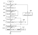
- step S01 it is determined whether or not the vehicle speed vibration fvsp is equal to or greater than a vehicle speed vibration reference secondary pressure lower limit regulation value (hereinafter referred to as fvsp_psec .: equivalent to a third predetermined value). If not, the process proceeds to step S03.
- fvsp_psec vehicle speed vibration reference secondary pressure lower limit regulation value
- FIG. 4 is a control block diagram for performing vehicle speed vibration component extraction processing according to the first embodiment.
- the vehicle speed conversion unit 101 converts the vehicle speed from the wheel speed sensor pulse period input from the wheel speed sensor 21R. Since the calculation cycle of the controller is fixed, the vehicle speed can be converted from the number of pulses input within the calculation cycle.
- the high-pass filter 102 extracts and outputs only the high frequency side signal from the converted vehicle speed signal. The vehicle speed fluctuation when traveling on a good road varies only at a low frequency due to the influence of the inertia of the vehicle. Therefore, the signal on the high frequency side is considered as a vibration component.
- the low-pass filter 103 smoothes the vehicle speed signal on the high frequency side.
- the frequency range in which a wheel can actually vibrate due to the influence of the inertia of the wheel is limited. Therefore, noise is removed by the low-pass filter 103, the vibration actually generated in the wheel is extracted, and the vehicle speed vibration fvsp which is a vibration component is extracted.
- step S02 the secondary pulley pressure Psec is set to Psec (fvsp) which is a value corresponding to the vehicle speed vibration fvsp. Specifically, the secondary pulley pressure Psec is set to increase as the vehicle speed vibration fvsp increases. That is, even if the wheel speed difference ⁇ vfr is not determined as a rough road in step S06, which will be described later, if the vehicle speed vibration fvsp actually increases, there is still concern about belt slip.
- step S03 the secondary pulley pressure Psec is set to the secondary pulley pressure Psec (n) calculated based on the normal control.
- the transition is performed while the secondary pulley pressure change rate ⁇ Psec is limited to a predetermined change rate ⁇ Psec_lim set in advance. To do. Thereby, the belt slip etc. accompanying the sudden change of the secondary pulley pressure Psec are avoided.
- step S04 the wheel speed difference ⁇ vfr, which is the difference between the rotational speed of the driving wheel detected by the wheel speed sensor 21F and the rotational speed of the driven wheel detected by the wheel speed sensor 21R, is determined to be entered in rough road detection described later. It is determined whether or not the wheel speed difference reference secondary pressure lower limit regulation value (hereinafter referred to as ⁇ vfr_psec: equivalent to the second predetermined value) is smaller than a threshold value ⁇ vfr_br (corresponding to the first predetermined value), and the condition is satisfied If so, the process proceeds to step S05. Otherwise, the process proceeds to step S06. In step S05, the secondary pulley pressure Psec is set to a magnitude corresponding to the wheel speed difference ⁇ vfr.
- ⁇ vfr_psec equivalent to the second predetermined value
- a function connecting the current primary pulley pressure Psec (Psec (fvsp) or Psec (n)) at ⁇ vfr_psec and the rough road control pressure P1 at ⁇ vfr_br is defined, and as the wheel speed difference ⁇ vfr increases, Ramp control is performed so that the secondary pulley pressure Psec increases toward the rough road control pressure P1.
- the secondary pulley pressure determined by the ramp control is referred to as Psec (fvsp, ⁇ vfr).
- step S06 whether or not the wheel speed difference ⁇ vfr is equal to or greater than a wheel speed difference reference primary rotation speed lower limit regulation value (hereinafter referred to as ⁇ vfr_npri: equivalent to a fourth predetermined value), or the vehicle speed vibration fvsp is a vehicle speed vibration reference. It is determined whether or not it is equal to or greater than a primary rotational speed lower limit regulation value (hereinafter referred to as fvsp_npri .: equivalent to a fifth predetermined value). If the condition is satisfied, the process proceeds to step S07. Otherwise, the process proceeds to step S08. move on.
- a wheel speed difference reference primary rotation speed lower limit regulation value hereinafter referred to as a fourth predetermined value
- fvsp_npri equivalent to a fifth predetermined value
- the minimum rotation restriction regulation process for controlling the CVT 1 is performed.
- the primary pulley minimum rotation speed Npri_min is a value that can ensure the pump discharge pressure even if the secondary pulley pressure Psec is requested to be P1 used in rough road control. It should be noted that when the rough road control process is performed before the start of the rough road control process, and then the rough road control process is started, the lock-up clutch 6c is released.
- step S08 the gear ratio G of CVT1 is controlled based on a normal shift map.
- the lock-up clutch 6c of the torque converter 6 in the lock-up state, and the primary rotational speed Npri and the engine rotational speed Ne coincide. Since the mechanical oil pump O / P is driven by the engine 5, when the secondary pulley pressure Psec is increased according to fvsp or ⁇ vfr, if the engine speed Ne decreases, a sufficient oil pump There is a possibility that the discharge pressure cannot be secured. Therefore, in order to ensure the oil pump discharge pressure of the mechanical oil pump O / P, the minimum rotation limit restricting process for setting the primary pulley minimum rotation speed Npri_min and controlling the gear ratio G to achieve this rotation speed is performed. carry out. As a result, the primary rotational speed Npri is secured, and thus the engine rotational speed Ne is secured, so that the oil pump discharge pressure of the mechanical oil pump O / P is secured and belt slippage is avoided.
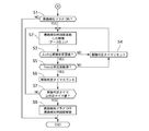
- step S09 it is determined whether or not the wheel speed difference ⁇ vfr is equal to or greater than the on road determination threshold ⁇ vfr_br for detecting a rough road. If the condition is satisfied, the process proceeds to step S010, and the rough road detection flag is set to ON. In other cases, the process proceeds to step S011, and the rough road detection flag is set to OFF. In step S1, it is determined whether or not the rough road detection flag is ON. If the rough road detection flag is ON, the process proceeds to step S2. If the rough road detection flag is OFF, that is, if the road is good, this control flow is terminated.
- step S2 rough road detection control is performed. Specifically, the lockup clutch 6c is released and the secondary pulley pressure Psec is increased to the rough road control pressure P1.
- step S3 it is determined whether or not the wheel speed difference ⁇ vfr is equal to or less than a release determination threshold value (corresponding to the sixth and eighth predetermined values). If the wheel speed difference ⁇ vfr is equal to or less than the release determination threshold value, the process proceeds to step S5. Advances to step S4. When the wheel speed sensor 21 is abnormal, it is determined that it is equal to or less than the release determination threshold value, and the process proceeds to step S5. This is to avoid the situation where it is impossible to cancel the control when the rough road is detected when the wheel speed sensor 21 is abnormal. This is because the continuation of the control at the time of detecting the rough road causes deterioration of fuel consumption.
- step S4 the release determination timer is reset, and the process returns to step S2 to continue the control when detecting a rough road.
- the release determination timer is a timer that counts up when the wheel speed difference becomes equal to or less than the release determination threshold.
- step S5 it is determined whether or not the vehicle speed vibration fvsp is equal to or less than a predetermined vibration value (corresponding to the seventh and ninth predetermined values). If the condition is satisfied, the process proceeds to step S6. Otherwise, the process proceeds to step S4. Return and reset the release judgment timer.
- the bad road determination is performed using the wheel speed difference in order to improve the response of the bad road detection. Therefore, if it is judged that the control at the time of rough road detection is ended using only the wheel speed difference, the control at the time of rough road detection is ended by the temporary convergence of the wheel speed difference even if it is actually a bad road. There is a risk.
- the end determination of the rough road detection control is added to the wheel speed difference ⁇ vfr and the end determination is performed by the vehicle speed vibration fvsp which is a vibration component of the vehicle speed. You can avoid ending.
- the vibration component is detected based on the sensor pulse period detected by the primary pulley rotation sensor 13. At this time, even if the gear ratio changes, the frequency of the change is extremely low, and therefore the influence can be eliminated by the low-pass filter. Then, it is determined whether or not the vibration of the primary pulley 2 is equal to or smaller than a predetermined vibration value. If the vibration is equal to or smaller than the predetermined vibration value, the process proceeds to step S6. Otherwise, the process returns to step S4 and the release determination timer is reset. That is, when an abnormality occurs in the wheel speed sensor 21 and the detected wheel speed difference increases regardless of the road surface state, the clamping force increases due to the rough road detection time control.
- the clamping force cannot be returned to the low clamping force in the normal state, and the fuel consumption may be deteriorated. Therefore, when the wheel speed sensor 21 is abnormal, the wheel speed difference is not used for the release determination, and only the vibration component of the primary pulley rotation sensor 13 is used for the release determination. The state can be returned to the low clamping force, and deterioration of fuel consumption can be suppressed.
- step S6 the cancellation determination timer is counted up.
- step S7 it is determined whether or not the count value of the release determination timer is greater than or equal to a predetermined timer value. If the count value is greater than or equal to the predetermined timer value, the process proceeds to step S8. Otherwise, the process returns to step S2 and a rough road is detected. Continue control.
- step S8 the rough road detection flag is turned OFF and the rough road detection control is released. At this time, when the primary pulley minimum rotation speed Npri_min set in step S07 is continuously set, the primary pulley minimum rotation speed Npri_min is also canceled.
- FIG. 5 is a time chart illustrating the rough road control process according to the first embodiment.
- the vehicle In the initial running state, the vehicle is running at a substantially constant speed, the rough road detection flag is OFF, and the release determination timer is counted up to a predetermined timer value.
- the secondary pulley pressure Psec is set to Psec (fvsp) which is a value corresponding to the vehicle speed vibration fvsp.
- the minimum rotation restriction regulation process is canceled and Psec (fvsp) is also changed to the secondary pulley pressure Psec (n) calculated based on the normal control. .
- the secondary pulley pressure Psec is shifted to a predetermined rate of change ⁇ Psec_lim so as not to change suddenly.
- the release determination timer is reset. Since the wheel speed difference ⁇ vfr increases and exceeds ⁇ vfr_psec, the secondary pulley pressure Psec gradually increases due to the ramp control. When the wheel speed difference ⁇ vfr exceeds ⁇ vfr_npri, the minimum rotation restriction is performed. When the wheel speed difference becomes greater than the determination threshold value at time t2, the rough road detection flag is set from OFF to ON, and rough road detection control is performed. Thereby, a wheel speed difference goes to a convergence direction. As described above, since the rough road is detected based on the wheel speed difference, the quick rough road can be detected and the belt slip can be suppressed.
- the release determination timer starts counting up.
- the count-up of the release determination timer is reset, so that the rough road detection flag is maintained ON and the rough road detection time control is continued. In this way, since the rough road detection flag is set using the release determination timer, it is possible to suppress fluctuations in the clamping force caused by the operation / non-operation of the rough road detection control.
- the vibration component is equal to or less than the predetermined vibration value, and the wheel speed difference is also below the release determination threshold value, so the count-up of the release determination timer is started.
- the count value of the release determination timer is counted up to a predetermined timer value at time t6
- the rough road detection flag is set from ON to OFF
- the rough road detection time control is terminated, and the secondary pulley pressure Psec is also set in advance.
- ⁇ Psec_lim a decrease starts toward the secondary pulley pressure Psec (n) of the normal control, and the minimum rotation restriction is also released.
- Step S4 wheel speed difference detection unit
- Step S09 bad road determination unit
- Step S2 for increasing the belt clamping force when the belt of the continuously variable transmission is clamped by the hydraulically controlled pulley when compared with the case where it is determined that the road is not bad (first belt clamping force increasing portion).
- Step S01 vibration detection unit for detecting vibration of the vehicle speed based on a detection value of the wheel speed sensor 21R (at least one of the first rotation speed sensor and the second rotation speed sensor); If the road is not determined to be a rough road, the wheel speed difference ⁇ vfr is not less than ⁇ vfr_psec (second predetermined value) smaller than ⁇ vfr_br in step S04, or the vehicle speed vibration fvsp is fvsp_psec (third predetermined value) in step S01.
- step S02 or S05 for increasing the belt clamping force compared to the case where the wheel speed difference ⁇ vfr is less than ⁇ vfr_psec and the vehicle speed vibration fvsp is less than fvsp_psec, Equipped with.
- the clamping force can be immediately increased when the driving wheel slips. Therefore, it is possible to prevent the belt from slipping due to an increase in the grip force of the drive wheel after the slip. Even before a bad road is detected, if the wheel speed difference ⁇ vfr is greater than or equal to ⁇ vfr_psec or the vehicle speed vibration fvsp is greater than or equal to fvsp_psec, there is a high possibility that belt slip will occur, or after that, the bad road In this case, belt slippage can be suppressed by increasing the belt clamping force.
- CVT1 continuously variable transmission
- step S06 the wheel speed difference ⁇ vfr is greater than ⁇ vfr_npri (fourth predetermined value) that is smaller than the input determination threshold, or the vehicle speed vibration fvsp is greater than or equal to fvsp_npri (fifth predetermined value).
- step S07 minimum rotation restricting unit
- Npri_min predetermined minimum rotational speed
- the lockup clutch 6c of the torque converter 6 in the running state, the lockup clutch 6c of the torque converter 6 is in the lockup state, and the primary rotational speed Npri and the engine rotational speed Ne coincide. Since the mechanical oil pump O / P is driven by the engine 5, when the secondary pulley pressure Psec is increased according to fvsp or ⁇ vfr, if the engine speed Ne decreases, a sufficient oil pump There is a possibility that the discharge pressure cannot be secured. Therefore, in order to ensure the oil pump discharge pressure of the mechanical oil pump O / P, the minimum rotation limit restricting process for setting the primary pulley minimum rotation speed Npri_min and controlling the gear ratio G to achieve this rotation speed is performed. carry out. As a result, the primary rotational speed Npri is secured, and thus the engine rotational speed Ne is secured, so that the oil pump discharge pressure of the mechanical oil pump O / P can be secured and belt slippage can be avoided.
- Npri_min is a preset constant value. Therefore, even if the minimum rotation restriction is performed, the engine speed does not fluctuate, and the uncomfortable feeling given to the driver can be suppressed.
- Step S07 starts the minimum rotation restriction, and when it is determined that the road is a rough road, the wheel speed difference ⁇ vfr is equal to or smaller than a release determination threshold (sixth predetermined value) smaller than ⁇ vfr_npri, and The regulation is continued until the vehicle speed vibration fvsp becomes equal to or less than a predetermined vibration value (seventh predetermined value) smaller than fvsp_npri. Therefore, the discharge pressure of the mechanical oil pump O / P can be sufficiently secured while the rough road control process is being performed.
- step S8 the lift canceling unit for decreasing the belt clamping force increased in step S2 is performed.
- the wheel speed difference ⁇ vfr and the vehicle speed vibration fvsp are each less than or equal to a predetermined value, the increased clamping force is reduced, so that it is possible to accurately determine that the road has been broken and the input torque increases rapidly.
- Example 2 Next, Example 2 will be described. Since the basic configuration is the same as that of the first embodiment, only different points will be described.
- a predetermined minimum rotation speed Npri_min set in advance is set.
- the minimum rotational speed Npri_min is set based on the secondary pulley pressure Psec (fvsp, ⁇ vfr) corresponding to the vehicle speed vibration fvsp and the wheel speed difference ⁇ vfr.
- the secondary pulley pressure Psec is the secondary pulley pressure Psec (fvsp) corresponding to the vehicle speed vibration fvsp when it is less than ⁇ vfr_psec, and the secondary pulley pressure Psec determined by the ramp control in step S05 when it is equal to or greater than ⁇ vfr_psec. (Fvsp, ⁇ vfr).
- the minimum rotational speed Npri_min (fvsp, ⁇ vfr) necessary for securing this hydraulic pressure can be calculated from the specific discharge amount of the mechanical oil pump O / P.
- Npri_min (fvsp, ⁇ vfr) (predetermined minimum rotational speed) is set to a higher rotational speed as the wheel speed difference ⁇ vfr is larger or the vehicle speed vibration fvsp is larger. Therefore, since the minimum necessary engine speed Ne according to the traveling state can be ensured, there is no need to set the engine speed Ne unnecessarily high, and fuel consumption can be improved.
- the value (seventh predetermined value) and the cancellation determination threshold (sixth predetermined value) are set to the same value, the cancellation condition for the rough road control process and the cancellation condition for the minimum rotation restriction restriction are set to different values. May be.
- the minimum rotation restriction restriction release condition may be set to a value higher than the rough road control process release condition, and the minimum rotation restriction restriction may be released earlier.
- Example 1 although the example applied to the front-wheel drive vehicle was shown, it can also be applied to a 4-wheel drive vehicle. In this case, since all are drive wheels, there is a possibility that a sufficient wheel speed difference does not occur. Therefore, in the rough road determination of step S09, (A) When the acceleration of each wheel is calculated, and the state where the acceleration is greater than the acceleration rising side entry threshold value considered to have increased due to slip has continued for a predetermined time. (B) The acceleration of each wheel is calculated and the acceleration is an obstacle. It is sufficient to introduce two conditions when a state smaller than the acceleration processing side entry threshold value, which is considered to have been reduced due to, continues for a predetermined time.
Landscapes
- Engineering & Computer Science (AREA)
- General Engineering & Computer Science (AREA)
- Mechanical Engineering (AREA)
- Control Of Transmission Device (AREA)
- Control Of Driving Devices And Active Controlling Of Vehicle (AREA)
Abstract
Description
ステップS01では、車速振動fvspが車速振動基準セカンダリ圧下限規制値(以下、fvsp_psecと記載する。:第3の所定値に相当)以上か否かを判断し、条件を満たす場合にはステップS02に進み、それ以外の場合にはステップS03に進む。
ステップS03では、セカンダリプーリ圧Psecを通常制御に基づいて演算されるセカンダリプーリ圧Psec(n)に設定する。このとき、セカンダリプーリ圧PsecがPsec(fvsp)に設定された状態からPsec(n)に移行する場合には、セカンダリプーリ圧変化率ΔPsecを予め設定された所定変化率ΔPsec_limに制限した状態で移行する。これにより、セカンダリプーリ圧Psecの急変に伴うベルト滑り等を回避する。
ステップS05では、セカンダリプーリ圧Psecを、車輪速差Δvfrに応じた大きさに設定する。具体的には、Δvfr_psecにおける現在のプライマリプーリ圧Psec(Psec(fvsp)もしくはPsec(n))と、Δvfr_brにおける悪路制御用圧力P1とを結ぶ関数を定義し、車輪速差Δvfrが大きくなるほど、セカンダリプーリ圧Psecが悪路制御用圧力P1に向けて大きくなるようにランプ制御する。以下、このランプ制御によって決定されるセカンダリプーリ圧をPsec(fvsp,Δvfr)と記載する。
ステップS07では、CVT1の変速比Gを、予め設定されたプライマリプーリ最低回転数Npri_minと、現在のセカンダリプーリ回転数Nsecとに基づいて算出(G=Npri_min/Nsec)し、この変速比Gに向けてCVT1を制御する最低回転制限規制処理を実施する。このプライマリプーリ最低回転数Npri_minは、仮にセカンダリプーリ圧Psecが悪路制御で使用されるP1を要求されたとしても確実にポンプ吐出圧を確保可能な値とする。尚、悪路制御処理の開始前に最低回転制限規制を行い、その後、悪路制御処理が開始された場合には、ロックアップクラッチ6cが解放される。このときは、変速比Gの制御に加えて、エンジン5に対し、プライマリプーリ最低回転数Npri_minに相当する回転数を要求し、機械式オイルポンプO/Pの吐出圧を確保する。
ステップS08では、CVT1の変速比Gを通常の変速マップに基づいて制御する。
ステップS1では、悪路検知フラグがONか否かを判断し、悪路検知フラグがONの場合はステップS2に進み、OFFの場合、すなわち良路の場合は本制御フローを終了する。
ステップS3では、車輪速差Δvfrが解除判定閾値(第6及び第8の所定値に相当)以下か否かを判定し、解除判定閾値以下の場合はステップS5に進み、解除判定閾値より大きいときはステップS4に進む。尚、車輪速センサ21の異常時は、解除判定閾値以下であると判定してステップS5に進む。車輪速センサ21の異常時に悪路検知時制御の解除ができなくなることを回避するためである。悪路検知時制御の継続は燃費の悪化を招くからである。
実施例1の悪路制御処理では、悪路検知の応答性を向上するために車輪速差を用いて悪路判定を行っている。よって、仮に車輪速差のみを用いて悪路検知時制御を終了する判断を行うと、実際には悪路であっても一時的な車輪速差の収束で悪路検知時制御を終了してしまう恐れがある。この場合、再度の悪路判定が即座に行われたとしても、挟持力を高めるには油圧制御の応答性の問題があり、ベルト滑りが発生する前に挟持力を高められないおそれがある。これに対し、実施例1では、悪路検知時制御の終了判断を車輪速差Δvfrに加え、車速の振動成分である車速振動fvspによって終了判断を行うため、不用意に悪路検知時制御が終了することを回避できる。
ステップS7では、解除判定タイマのカウント値が所定タイマ値以上か以下か否かを判定し、所定タイマ値以上の場合はステップS8に進み、それ以外の場合はステップS2に戻って悪路検知時制御を継続する。
ステップS8では、悪路検知フラグをOFFするとともに、悪路検知時制御を解除する。このとき、ステップS07にて設定されたプライマリプーリ最低回転数Npri_minが継続して設定されている場合には、このプライマリプーリ最低回転数Npri_minも解除する。
時刻t01において、車速振動fvspがfvsp_psecを超えると、セカンダリプーリ圧Psecを車速振動fvspに応じた値であるPsec(fvsp)に設定する。また、同時に車速振動fvspがfvsp_npriを超えるため、CVT1の変速比Gを、予め設定されたプライマリプーリ最低回転数Npri_minと、現在のセカンダリプーリ回転数Nsecとに基づいて算出(G=Npri_min/Nsec)し、この変速比Gに向けてCVT1を制御する最低回転制限規制処理を実施する。
時刻t02において、車速振動fvspがfvsp_psec及びfvsp_npriを下回ると、最低回転制限規制処理が解除されると共に、Psec(fvsp)も通常制御に基づいて演算されるセカンダリプーリ圧Psec(n)に変更される。このとき、セカンダリプーリ圧Psecが急変しないよう、所定変化率ΔPsec_limに制限した状態で移行させる。
時刻t2において、車輪速差が入り判定閾値以上となると、悪路検知フラグがOFFからONにセットされ、悪路検知時制御が実施される。これにより、車輪速差は収束方向に向かう。このように、車輪速差に基づいて悪路検知が行われるため、素早い悪路検知が可能となり、ベルト滑りを抑制できる。
時刻t4において、車輪速差が再度解除判定閾値を上回ると、解除判定タイマのカウントアップはリセットされるため、悪路検知フラグはONのまま維持され、悪路検知時制御が継続される。このように、解除判定タイマを用いて悪路検知フラグをセットするため、悪路検知制御の作動・非作動に伴う挟持力の変動を抑制できる。
時刻t5において、悪路から良路へと移行し、振動成分が所定振動値以下となり、かつ、車輪速差も解除判定閾値を下回っているため、解除判定タイマのカウントアップが開始される。そして、時刻t6において、解除判定タイマのカウント値が所定タイマ値までカウントされると、悪路検知フラグがONからOFFに設定され、悪路検知時制御が終了すると共に、セカンダリプーリ圧Psecも予め設定された所定変化率ΔPsec_limにより通常制御のセカンダリプーリ圧Psec(n)に向かって低下を開始すると共に、最低回転制限規制も解除される。このように、悪路検知制御の解除時には、車輪速差だけでなく、振動成分の低下を併せて判断することで、より安定的に解除判定を達成できる。
従動輪の回転速度を検出する車輪速センサ21R(第2の回転速度センサ)と、
車輪速センサ21Fの検出値と車輪速センサ21Rの検出値から駆動輪と従動輪との車輪速差を検出するステップS04(車輪速差検出部)と、
車輪速差が入り判定閾値Δvfr_br(第1の所定値)以上になった場合、走行中の路面が悪路であると判定するステップS09(悪路判定部)と、
悪路と判定した場合、悪路と判定しない場合に比べて、無段変速機のベルトを油圧制御されたプーリによって挟み込むときのベルト挟持力を高くするステップS2(第1ベルト挟持力上昇部)と、
車輪速センサ21R(第1の回転速度センサと第2の回転速度センサの少なくとも一方)の検出値に基づいて車速の振動を検出するステップS01(振動検出部)と、
悪路と判定されていない場合であって、ステップS04において車輪速差ΔvfrがΔvfr_brより小さなΔvfr_psec(第2の所定値)以上、又は、ステップS01において車速振動fvspがfvsp_psec(第3の所定値)以上のときは、車輪速差ΔvfrがΔvfr_psec未満、かつ、車速振動fvspがfvsp_psec未満の場合に比べて、ベルト挟持力を高くするステップS02もしくはS05(第2ベルト挟持力上昇部)と、
を備えた。
悪路と判定されていない場合であって、ステップS06において車輪速差Δvfrが入り判定閾値よりも小さなΔvfr_npri(第4の所定値)以上、又は車速振動fvspがfvsp_npri(第5の所定値)以上のときは、エンジン5の回転数を、Npri_min(所定の最低回転数)以上となるように規制するステップS07(最低回転規制部)を設けた。
基本的に、CVT1は、走行状態ではトルクコンバータ6のロックアップクラッチ6cがロックアップ状態とされ、プライマリ回転数Npriとエンジン回転数Neとは一致している。機械式オイルポンプO/Pはエンジン5により駆動されているため、セカンダリプーリ圧PsecをfvspやΔvfrに応じて増大させているときに、エンジン回転数Neが低下してしまうと、十分なオイルポンプ吐出圧を確保できないおそれがある。そこで、機械式オイルポンプO/Pのオイルポンプ吐出圧を確保するために、プライマリプーリ最低回転数Npri_minを設定し、この回転数を達成するための変速比Gに制御する最低回転制限規制処理を実施する。これにより、プライマリ回転数Npriを確保し、ひいてはエンジン回転数Neを確保することで、機械式オイルポンプO/Pのオイルポンプ吐出圧を確保し、ベルト滑りを回避できる。
よって、悪路制御処理が実施されている間は、機械式オイルポンプO/Pの吐出圧を十分に確保できる。
車輪速差Δvfrと車速振動fvspとがそれぞれ所定値以下となってから、高めた挟持力を低下させるため、悪路を脱したことを正確に判定することができ、急激に入力トルクが増大するような悪路を走行している状態にもかかわらず挟持力を低下させることを回避でき、ベルト滑りを防止できる。更に、車輪速差と車速の振動が収束すれば挟持力が良路に応じた挟持力に低下するため、良路に戻っても無駄に挟持力が高い状態で走行する時間を短縮でき、燃費の悪化を抑制できる。
次に、実施例2について説明する。基本的な構成は実施例1と同じであるため、異なる点についてのみ説明する。
実施例1では、ステップS07の最低回転制限規制を行う際、予め設定された所定の最低回転数Npri_minを設定した。これに対し、実施例2では、車速振動fvspや車輪速差Δvfrに応じたセカンダリプーリ圧Psec(fvsp,Δvfr)に基づいて最低回転数Npri_minを設定するものである。具体的には、セカンダリプーリ圧Psecは、Δvfr_psec未満のときは車速振動fvspに応じたセカンダリプーリ圧Psec(fvsp)であり、Δvfr_psec以上のときはステップS05のランプ制御によって決定されるセカンダリプーリ圧Psec(fvsp,Δvfr)である。このように、セカンダリプーリ圧Psecが決定されると、この油圧を確保するのに必要な最低回転数Npri_min(fvsp,Δvfr)が機械式オイルポンプO/Pの固有吐出量から算出できる。この最低回転数Npri_min(fvsp,Δvfr)を用いてCVT1の変速比Gを算出(G=Npri_min(fvsp,Δvfr)/Nsec)し、この変速比Gに向けてCVT1を制御する。これにより、走行状態に応じた必要最小限のエンジン回転数を確保することができるため、燃費を改善できる。
(6)Npri_min(fvsp,Δvfr)(所定の最低回転数)は、車輪速差Δvfrが大きいほど、又は、車速振動fvspが大きいほど高い回転数に設定する。
よって、走行状態に応じた必要最小限のエンジン回転数Neを確保することができるため、不要にエンジン回転数Neを高めに設定する必要が無く、燃費を改善できる。
例えば、実施例1では、悪路制御処理の解除条件である所定振動値(第7の所定値)や解除判定閾値(第8の所定値)と、最低回転制限規制の解除条件である所定振動値(第7の所定値)や解除判定閾値(第6の所定値)とを同じ値に設定したが、悪路制御処理の解除条件と最低回転制限規制の解除条件とを異なる値に設定してもよい。例えば、最低回転制限規制の解除条件を悪路制御処理の解除条件よりも高めの値に設定し、早めに最低回転制限規制を解除してもよい。
(a)各輪の加速度を算出し、加速度がスリップにより上昇したと考えられる加速度上昇側入り判定閾値より大きい状態が所定時間継続した場合
(b)各輪の加速度を算出し、加速度が障害物により低下したと考えられる加速度加工側入り判定閾値より小さい状態が所定時間継続した場合
の二つの条件を導入すればよい。
この場合、前後輪の車輪速差が入り判定閾値以上となった場合も含めた3つの条件のうち、いずれかが成立すれば悪路と判定することで、効果的に悪路検知を行える。尚、4輪駆動車で上記条件により悪路判定した後、悪路検知制御を解除するにあたっては、車輪速差と車速振動の条件によって悪路検知制御を解除すればよい。これにより、良路に復帰した場合や、悪路であると誤判定した場合に素早く挟持力を低下できるため、燃費の悪化を抑制できる。
Claims (6)
- 駆動輪の回転速度を検出する第1の回転速度センサと、
従動輪の回転速度を検出する第2の回転速度センサと、
前記第1の回転速度センサの検出値と前記第2の回転センサの検出値から前記駆動輪と前記従動輪との車輪速差を検出する車輪速差検出部と、
前記車輪速差が第1の所定値以上になった場合、走行中の路面が悪路であると判定する悪路判定部と、
前記悪路と判定した場合、悪路と判定しない場合に比べて、無段変速機のベルトを油圧制御されたプーリによって挟み込むときのベルト挟持力を高くする第1ベルト挟持力上昇部と、
前記第1の回転速度センサと前記第2の回転速度センサの少なくとも一方の検出値に基づいて車速の振動を表す車速振動値を検出する振動検出部と、
前記悪路と判定されていない場合であって、前記車輪速差が前記第1の所定値より小さな第2の所定値以上、又は、前記車速振動値が第3の所定値以上のときは、前記車輪速差が前記第2の所定値未満、かつ、前記車速振動値が第3の所定値未満の場合に比べて、前記ベルト挟持力を高くする第2ベルト挟持力上昇部と、
を備えている無段変速機の制御装置。 - 請求項1に記載の無段変速機の制御装置において、
前記無段変速機は、駆動源により駆動される機械式オイルポンプの吐出圧に基づいてプーリの油圧制御を行う変速機であり、
前記悪路と判定されていない場合であって、前記車輪速差が前記第1の所定値よりも小さな第4の所定値以上、又は前記車速振動が第5の所定値以上のときは、前記駆動源の回転数を、所定の最低回転数以上となるように規制する最低回転制限規制部を設けてある無段変速機の制御装置。 - 請求項2に記載の無段変速機の制御装置において、
前記所定の最低回転数は、予め設定された一定値である無段変速機の制御装置。 - 請求項2に記載の無段変速機の制御装置において、
前記所定の最低回転数は、前記車輪速差が大きいほど、又は、前記検出された車速の振動が大きいほど高い回転数に設定するようにした無段変速機の制御装置。 - 請求項2~4のいずれか一つに記載の無段変速機の制御装置において、
前記最低回転制限規制部は、前記規制を開始し、かつ、前記悪路と判定されたときは、前記車輪速差が前記第4の所定値より小さな第6の所定値以下であって、かつ、前記車速振動が前記第5の所定値より小さな第7の所定値以下となるまで規制を継続するものである無段変速機の制御装置。 - 請求項1~5のいずれか一つに記載の無段変速機の制御装置において、
前記第1ベルト挟持力上昇部によりベルト挟持力を高くしているときに、前記車輪速差が前記第1の所定値より小さな第8の所定値以下であって、かつ、前記車速振動が前記第3の所定値より小さな第9の所定値以下となった場合には、前記第1ベルト挟持力上昇部により高くしたベルト挟持力を低下させる上昇解除部を設けてある無段変速機の制御装置。
Priority Applications (5)
| Application Number | Priority Date | Filing Date | Title |
|---|---|---|---|
| US15/559,472 US10316967B2 (en) | 2015-03-20 | 2016-02-03 | Control device for continuously variable transmission |
| KR1020177025910A KR102004635B1 (ko) | 2015-03-20 | 2016-02-03 | 무단 변속기의 제어 장치 |
| EP16768163.4A EP3273111A4 (en) | 2015-03-20 | 2016-02-03 | Control device for continuously variable transmission |
| CN201680017143.0A CN107429837B (zh) | 2015-03-20 | 2016-02-03 | 无级变速器的控制装置 |
| JP2017507558A JP6340135B2 (ja) | 2015-03-20 | 2016-02-03 | 無段変速機の制御装置 |
Applications Claiming Priority (2)
| Application Number | Priority Date | Filing Date | Title |
|---|---|---|---|
| JP2015-057518 | 2015-03-20 | ||
| JP2015057518 | 2015-03-20 |
Publications (1)
| Publication Number | Publication Date |
|---|---|
| WO2016152260A1 true WO2016152260A1 (ja) | 2016-09-29 |
Family
ID=56977310
Family Applications (1)
| Application Number | Title | Priority Date | Filing Date |
|---|---|---|---|
| PCT/JP2016/053167 Ceased WO2016152260A1 (ja) | 2015-03-20 | 2016-02-03 | 無段変速機の制御装置 |
Country Status (6)
| Country | Link |
|---|---|
| US (1) | US10316967B2 (ja) |
| EP (1) | EP3273111A4 (ja) |
| JP (1) | JP6340135B2 (ja) |
| KR (1) | KR102004635B1 (ja) |
| CN (1) | CN107429837B (ja) |
| WO (1) | WO2016152260A1 (ja) |
Cited By (2)
| Publication number | Priority date | Publication date | Assignee | Title |
|---|---|---|---|---|
| JP2019011003A (ja) * | 2017-06-30 | 2019-01-24 | ジヤトコ株式会社 | 車両制御装置および車両制御方法 |
| KR20190111487A (ko) * | 2018-03-23 | 2019-10-02 | 현대자동차주식회사 | 무단변속기 차량의 풀리 제어방법 |
Families Citing this family (5)
| Publication number | Priority date | Publication date | Assignee | Title |
|---|---|---|---|---|
| US10641391B2 (en) * | 2018-04-23 | 2020-05-05 | GM Global Technology Operations LLC | System and method for CVT clamp control based on oncoming conditions in a vehicle propulsion system |
| KR20200098231A (ko) | 2019-02-12 | 2020-08-20 | 현대자동차주식회사 | 차량의 변속 제어 장치 및 방법 |
| CN111963671B (zh) * | 2020-08-18 | 2021-12-31 | 盛瑞传动股份有限公司 | 自动变速箱颠簸路面控制方法及控制装置 |
| CN112797156B (zh) * | 2021-02-07 | 2022-04-26 | 潍柴动力股份有限公司 | 一种换挡控制方法、装置及控制器 |
| CN113464638B (zh) * | 2021-06-30 | 2022-06-28 | 中国第一汽车股份有限公司 | 一种手动模式换挡控制方法和车辆 |
Citations (5)
| Publication number | Priority date | Publication date | Assignee | Title |
|---|---|---|---|---|
| JP2004084773A (ja) * | 2002-08-26 | 2004-03-18 | Toyota Motor Corp | 路面入力検出装置および変速機の制御装置 |
| JP2004176729A (ja) * | 2002-11-22 | 2004-06-24 | Toyota Motor Corp | 車両用動力伝達機構の制御装置 |
| JP2005114088A (ja) * | 2003-10-09 | 2005-04-28 | Honda Motor Co Ltd | 無段変速機の制御装置 |
| JP2007162796A (ja) * | 2005-12-13 | 2007-06-28 | Jatco Ltd | 路面状態判定装置および無段変速機 |
| JP2015030302A (ja) * | 2013-07-31 | 2015-02-16 | アイシン・エィ・ダブリュ株式会社 | 車両用駆動装置の制御装置 |
Family Cites Families (6)
| Publication number | Priority date | Publication date | Assignee | Title |
|---|---|---|---|---|
| JP2003269591A (ja) * | 2002-03-14 | 2003-09-25 | Toyota Motor Corp | 路面状態検出装置および無段変速機の制御装置 |
| DE10354705A1 (de) * | 2003-11-22 | 2005-06-30 | Zf Transmission Technologies L.L.C., Batavia | Verfahren zur Einstellung eines optimalen Anpressdruckes an den Scheiben eines Variators eines stufenlosen Getriebes |
| JP2009243565A (ja) * | 2008-03-31 | 2009-10-22 | Toyota Motor Corp | ベルト式無段変速機の制御装置 |
| EP3115649A4 (en) * | 2014-03-03 | 2017-06-21 | Jatco Ltd | Vehicle stepless transmission control device |
| US10006542B2 (en) * | 2014-07-30 | 2018-06-26 | Jatco Ltd | Controller for continuously variable transmission |
| JP6607205B2 (ja) * | 2017-01-19 | 2019-11-20 | トヨタ自動車株式会社 | 車両の制御装置 |
-
2016
- 2016-02-03 KR KR1020177025910A patent/KR102004635B1/ko not_active Expired - Fee Related
- 2016-02-03 EP EP16768163.4A patent/EP3273111A4/en not_active Withdrawn
- 2016-02-03 JP JP2017507558A patent/JP6340135B2/ja active Active
- 2016-02-03 CN CN201680017143.0A patent/CN107429837B/zh active Active
- 2016-02-03 WO PCT/JP2016/053167 patent/WO2016152260A1/ja not_active Ceased
- 2016-02-03 US US15/559,472 patent/US10316967B2/en active Active
Patent Citations (5)
| Publication number | Priority date | Publication date | Assignee | Title |
|---|---|---|---|---|
| JP2004084773A (ja) * | 2002-08-26 | 2004-03-18 | Toyota Motor Corp | 路面入力検出装置および変速機の制御装置 |
| JP2004176729A (ja) * | 2002-11-22 | 2004-06-24 | Toyota Motor Corp | 車両用動力伝達機構の制御装置 |
| JP2005114088A (ja) * | 2003-10-09 | 2005-04-28 | Honda Motor Co Ltd | 無段変速機の制御装置 |
| JP2007162796A (ja) * | 2005-12-13 | 2007-06-28 | Jatco Ltd | 路面状態判定装置および無段変速機 |
| JP2015030302A (ja) * | 2013-07-31 | 2015-02-16 | アイシン・エィ・ダブリュ株式会社 | 車両用駆動装置の制御装置 |
Cited By (3)
| Publication number | Priority date | Publication date | Assignee | Title |
|---|---|---|---|---|
| JP2019011003A (ja) * | 2017-06-30 | 2019-01-24 | ジヤトコ株式会社 | 車両制御装置および車両制御方法 |
| KR20190111487A (ko) * | 2018-03-23 | 2019-10-02 | 현대자동차주식회사 | 무단변속기 차량의 풀리 제어방법 |
| KR102532321B1 (ko) * | 2018-03-23 | 2023-05-15 | 현대자동차주식회사 | 무단변속기 차량의 풀리 제어방법 |
Also Published As
| Publication number | Publication date |
|---|---|
| EP3273111A4 (en) | 2018-05-02 |
| JPWO2016152260A1 (ja) | 2017-10-19 |
| JP6340135B2 (ja) | 2018-06-06 |
| US10316967B2 (en) | 2019-06-11 |
| CN107429837A (zh) | 2017-12-01 |
| KR20170118162A (ko) | 2017-10-24 |
| KR102004635B1 (ko) | 2019-07-26 |
| CN107429837B (zh) | 2019-05-21 |
| EP3273111A1 (en) | 2018-01-24 |
| US20180119813A1 (en) | 2018-05-03 |
Similar Documents
| Publication | Publication Date | Title |
|---|---|---|
| JP6340135B2 (ja) | 無段変速機の制御装置 | |
| JP6326498B2 (ja) | 無段変速機の制御装置 | |
| JP6019630B2 (ja) | 路面勾配推定装置 | |
| US10378644B2 (en) | Control device for automatic transmission for vehicle | |
| KR102532321B1 (ko) | 무단변속기 차량의 풀리 제어방법 | |
| CN106062430B (zh) | 车辆用无级变速器的控制装置 | |
| JP6213502B2 (ja) | 車両の制御装置 | |
| JP5937627B2 (ja) | 惰性走行制御装置及び惰性走行制御方法 | |
| JP6326484B2 (ja) | 車両用無段変速機の制御装置 | |
| JP2005030511A (ja) | 無段変速機を備えた車両の制御装置 | |
| JP2007162796A (ja) | 路面状態判定装置および無段変速機 | |
| JP2008045607A (ja) | 無段変速機用制御装置 | |
| KR102458756B1 (ko) | 무단변속기 차량의 제어방법 및 제어장치 | |
| JP2011247305A (ja) | 車両用自動変速機の制御装置 | |
| JP2017048706A (ja) | 車両用駆動制御装置及び車両用駆動制御装置の制御方法 | |
| JP2014134273A (ja) | 車両用無段変速機の変速制御装置 |
Legal Events
| Date | Code | Title | Description |
|---|---|---|---|
| 121 | Ep: the epo has been informed by wipo that ep was designated in this application |
Ref document number: 16768163 Country of ref document: EP Kind code of ref document: A1 |
|
| ENP | Entry into the national phase |
Ref document number: 2017507558 Country of ref document: JP Kind code of ref document: A |
|
| ENP | Entry into the national phase |
Ref document number: 20177025910 Country of ref document: KR Kind code of ref document: A |
|
| WWE | Wipo information: entry into national phase |
Ref document number: 15559472 Country of ref document: US |
|
| NENP | Non-entry into the national phase |
Ref country code: DE |
|
| REEP | Request for entry into the european phase |
Ref document number: 2016768163 Country of ref document: EP |