WO2016152309A1 - 可視像形成装置及び画像形成装置 - Google Patents
可視像形成装置及び画像形成装置 Download PDFInfo
- Publication number
- WO2016152309A1 WO2016152309A1 PCT/JP2016/054175 JP2016054175W WO2016152309A1 WO 2016152309 A1 WO2016152309 A1 WO 2016152309A1 JP 2016054175 W JP2016054175 W JP 2016054175W WO 2016152309 A1 WO2016152309 A1 WO 2016152309A1
- Authority
- WO
- WIPO (PCT)
- Prior art keywords
- image
- screen
- unit
- visible
- image forming
- Prior art date
- Legal status (The legal status is an assumption and is not a legal conclusion. Google has not performed a legal analysis and makes no representation as to the accuracy of the status listed.)
- Ceased
Links
Images




Classifications
-
- H—ELECTRICITY
- H04—ELECTRIC COMMUNICATION TECHNIQUE
- H04N—PICTORIAL COMMUNICATION, e.g. TELEVISION
- H04N1/00—Scanning, transmission or reproduction of documents or the like, e.g. facsimile transmission; Details thereof
- H04N1/00127—Connection or combination of a still picture apparatus with another apparatus, e.g. for storage, processing or transmission of still picture signals or of information associated with a still picture
- H04N1/00249—Connection or combination of a still picture apparatus with another apparatus, e.g. for storage, processing or transmission of still picture signals or of information associated with a still picture with a photographic apparatus, e.g. a photographic printer or a projector
- H04N1/00267—Connection or combination of a still picture apparatus with another apparatus, e.g. for storage, processing or transmission of still picture signals or of information associated with a still picture with a photographic apparatus, e.g. a photographic printer or a projector with a viewing or projecting apparatus, e.g. for reading image information from a film
-
- B—PERFORMING OPERATIONS; TRANSPORTING
- B41—PRINTING; LINING MACHINES; TYPEWRITERS; STAMPS
- B41J—TYPEWRITERS; SELECTIVE PRINTING MECHANISMS, i.e. MECHANISMS PRINTING OTHERWISE THAN FROM A FORME; CORRECTION OF TYPOGRAPHICAL ERRORS
- B41J29/00—Details of, or accessories for, typewriters or selective printing mechanisms not otherwise provided for
- B41J29/42—Scales and indicators, e.g. for determining side margins
-
- G—PHYSICS
- G02—OPTICS
- G02B—OPTICAL ELEMENTS, SYSTEMS OR APPARATUS
- G02B30/00—Optical systems or apparatus for producing three-dimensional [3D] effects, e.g. stereoscopic images
- G02B30/50—Optical systems or apparatus for producing three-dimensional [3D] effects, e.g. stereoscopic images the image being built up from image elements distributed over a three-dimensional [3D] volume, e.g. voxels
- G02B30/56—Optical systems or apparatus for producing three-dimensional [3D] effects, e.g. stereoscopic images the image being built up from image elements distributed over a three-dimensional [3D] volume, e.g. voxels by projecting aerial or floating images
-
- G—PHYSICS
- G03—PHOTOGRAPHY; CINEMATOGRAPHY; ANALOGOUS TECHNIQUES USING WAVES OTHER THAN OPTICAL WAVES; ELECTROGRAPHY; HOLOGRAPHY
- G03B—APPARATUS OR ARRANGEMENTS FOR TAKING PHOTOGRAPHS OR FOR PROJECTING OR VIEWING THEM; APPARATUS OR ARRANGEMENTS EMPLOYING ANALOGOUS TECHNIQUES USING WAVES OTHER THAN OPTICAL WAVES; ACCESSORIES THEREFOR
- G03B17/00—Details of cameras or camera bodies; Accessories therefor
- G03B17/24—Details of cameras or camera bodies; Accessories therefor with means for separately producing marks on the film, e.g. title, time of exposure
-
- G—PHYSICS
- G03—PHOTOGRAPHY; CINEMATOGRAPHY; ANALOGOUS TECHNIQUES USING WAVES OTHER THAN OPTICAL WAVES; ELECTROGRAPHY; HOLOGRAPHY
- G03G—ELECTROGRAPHY; ELECTROPHOTOGRAPHY; MAGNETOGRAPHY
- G03G15/00—Apparatus for electrographic processes using a charge pattern
- G03G15/50—Machine control of apparatus for electrographic processes using a charge pattern, e.g. regulating differents parts of the machine, multimode copiers, microprocessor control
- G03G15/5016—User-machine interface; Display panels; Control console
-
- G—PHYSICS
- G09—EDUCATION; CRYPTOGRAPHY; DISPLAY; ADVERTISING; SEALS
- G09G—ARRANGEMENTS OR CIRCUITS FOR CONTROL OF INDICATING DEVICES USING STATIC MEANS TO PRESENT VARIABLE INFORMATION
- G09G3/00—Control arrangements or circuits, of interest only in connection with visual indicators other than cathode-ray tubes
- G09G3/001—Control arrangements or circuits, of interest only in connection with visual indicators other than cathode-ray tubes using specific devices not provided for in groups G09G3/02 - G09G3/36, e.g. using an intermediate record carrier such as a film slide; Projection systems; Display of non-alphanumerical information, solely or in combination with alphanumerical information, e.g. digital display on projected diapositive as background
- G09G3/002—Control arrangements or circuits, of interest only in connection with visual indicators other than cathode-ray tubes using specific devices not provided for in groups G09G3/02 - G09G3/36, e.g. using an intermediate record carrier such as a film slide; Projection systems; Display of non-alphanumerical information, solely or in combination with alphanumerical information, e.g. digital display on projected diapositive as background to project the image of a two-dimensional display, such as an array of light emitting or modulating elements or a CRT
-
- G—PHYSICS
- G09—EDUCATION; CRYPTOGRAPHY; DISPLAY; ADVERTISING; SEALS
- G09G—ARRANGEMENTS OR CIRCUITS FOR CONTROL OF INDICATING DEVICES USING STATIC MEANS TO PRESENT VARIABLE INFORMATION
- G09G5/00—Control arrangements or circuits for visual indicators common to cathode-ray tube indicators and other visual indicators
-
- G—PHYSICS
- G09—EDUCATION; CRYPTOGRAPHY; DISPLAY; ADVERTISING; SEALS
- G09G—ARRANGEMENTS OR CIRCUITS FOR CONTROL OF INDICATING DEVICES USING STATIC MEANS TO PRESENT VARIABLE INFORMATION
- G09G2340/00—Aspects of display data processing
- G09G2340/14—Solving problems related to the presentation of information to be displayed
-
- G—PHYSICS
- G09—EDUCATION; CRYPTOGRAPHY; DISPLAY; ADVERTISING; SEALS
- G09G—ARRANGEMENTS OR CIRCUITS FOR CONTROL OF INDICATING DEVICES USING STATIC MEANS TO PRESENT VARIABLE INFORMATION
- G09G2354/00—Aspects of interface with display user
-
- G—PHYSICS
- G09—EDUCATION; CRYPTOGRAPHY; DISPLAY; ADVERTISING; SEALS
- G09G—ARRANGEMENTS OR CIRCUITS FOR CONTROL OF INDICATING DEVICES USING STATIC MEANS TO PRESENT VARIABLE INFORMATION
- G09G2358/00—Arrangements for display data security
-
- H—ELECTRICITY
- H04—ELECTRIC COMMUNICATION TECHNIQUE
- H04N—PICTORIAL COMMUNICATION, e.g. TELEVISION
- H04N2201/00—Indexing scheme relating to scanning, transmission or reproduction of documents or the like, and to details thereof
- H04N2201/0077—Types of the still picture apparatus
- H04N2201/0089—Image display device
-
- H—ELECTRICITY
- H04—ELECTRIC COMMUNICATION TECHNIQUE
- H04N—PICTORIAL COMMUNICATION, e.g. TELEVISION
- H04N2201/00—Indexing scheme relating to scanning, transmission or reproduction of documents or the like, and to details thereof
- H04N2201/0077—Types of the still picture apparatus
- H04N2201/0094—Multifunctional device, i.e. a device capable of all of reading, reproducing, copying, facsimile transception, file transception
Definitions
- the present invention relates to a visible image forming apparatus and an image forming apparatus, and more particularly to a technique for forming an operation screen in the air as a visible image.
- Patent Document 3 proposes a vehicle interior aerial display device that displays necessary information by forming a visible image in a space in an automobile.
- information necessary for a vehicle occupant can be displayed at a position that is easily visible to the occupant in a space in the vehicle interior instead of a display panel attached to the vehicle interior.
- the optical imaging device disclosed in Patent Document 4 below receives and reflects light emitted from an object or a display device, and is positioned symmetrically with the object or display device with the optical imaging device interposed therebetween. An object image is formed in the air by converging the reflected light.
- an image forming apparatus as a multifunction machine having multiple functions such as a copy, a printer, a scanner, and a fax machine. It can be displayed in the air.
- the present invention has been made in view of the above circumstances, and it is an object of the present invention to make predetermined private information difficult to see other than the operator even when an operation screen is displayed in the air.
- a visible image forming apparatus includes a visible image forming unit that forms a visible image in the air, A screen image creation unit for creating a screen image; A control unit that causes the visible image forming unit to form a visible image of the screen image created by the screen image creating unit, When the visible image includes predetermined private information, the screen image creating unit determines the private information with respect to the main screen in advance so that the private information is difficult to be seen by anyone other than the operator. A screen image inclined at a given angle is created, and the control unit forms a visible image of the created screen image by the visible image forming unit.
- An image forming apparatus includes an image forming unit that forms an image on a recording medium, The control unit causes the screen image creation unit to create an operation screen for receiving an instruction regarding the image forming unit, and causes the visible image formation unit to form a visible image of the operation screen in the air.
- An image forming apparatus includes an image forming unit that forms an image on a recording medium, The control unit causes the screen image creation unit to create an operation screen for receiving an instruction regarding the image forming unit, and causes the visible image formation unit to form a visible image of the operation screen in the air.
- the private information when the private image includes predetermined private information, the private information is inclined at a predetermined angle with respect to the main screen of the screen image. It can be made difficult to see other than the operator.
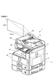
- FIG. 1 is a perspective view illustrating an appearance of an image forming apparatus according to an embodiment of the present invention.
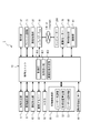
- 2 is a functional block diagram illustrating a main internal configuration of the image forming apparatus.
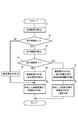
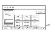
- FIG. It is a flowchart which shows the process which forms the visible image of an operation screen by a visible image formation part. It is a figure which shows an example of the screen image produced by the screen image creation part. It is a figure which shows the state in which the visible image as an operation screen is formed in the air. It is a figure which shows the state in which the visible image as an operation screen is formed in the air. It is a figure which shows an example of the screen image produced by the screen image creation part. It is a figure which shows an example of the screen image seen from the arrow A direction in FIG. 7A.
- FIG. 1 is a perspective view showing an appearance of an image forming apparatus according to an embodiment of the present invention.
- the image forming apparatus 1 is a multifunction machine having a plurality of functions such as a facsimile communication function, a copy function, a printer function, and a scanner function. As shown in FIG. 1, the image forming apparatus 1 includes an apparatus main body 2, an image reading unit 5 disposed above the apparatus main body 2, and a connecting unit provided between the image reading unit 5 and the apparatus main body 2. 3.
- a plurality of components for realizing various functions of the image forming apparatus 1 are accommodated in the casing 7 that constitutes the outline of the image forming apparatus 1.
- the housing 7 accommodates the image reading unit 5, the image forming unit 12 (FIG. 2), the fixing unit, the paper feeding unit 30, and the visible image forming unit 50 according to an embodiment of the present invention. Yes.
- the image reading unit 5 is an ADF (Auto Document Feeder) having a document conveying unit 6 and a scanner that optically reads a document conveyed by the document conveying unit 6 or a document placed on a contact glass (not shown). is there.
- the image reading unit 5 acquires image data that is an image forming target by reading one document at a time for facsimile transmission.
- the image forming unit 12 includes a photosensitive drum, a charging device, an exposure device, a developing device, and a transfer device.
- the recording paper on which the image has been formed is discharged to the discharge tray 4 after undergoing fixing processing by the fixing unit.
- the visible image forming unit 50 forms a visible image in the air.
- the visible image forming unit 50 intermittently emits invisible laser light, condenses the laser light with a lens, a mirror, or the like to generate plasma, and the visible light emitted from the plasma produces characters, A visible image such as an image is formed in the air (the visible image forming method is disclosed in, for example, Japanese Patent Application Laid-Open Nos. 2003-233339 and 2007-206588).
- the visible image forming unit 50 includes an optical imaging device, receives and reflects light emitted from the display device, and is symmetrical with the display device with the optical imaging device interposed therebetween.
- An object image is formed in the air by converging the reflected light at a position (a visible image forming method is disclosed in, for example, Japanese Patent Application Laid-Open No. 2013-127625).
- a visible image forming method is disclosed in, for example, Japanese Patent Application Laid-Open No. 2013-127625.
- description will be made assuming that the visible image forming unit 50 has the configuration (1).
- the operation unit 47 is, for example, a setting that is input by operating a start key for instructing execution of a function that can be performed by the image forming apparatus 1 and an operation screen indicated by a visible image formed by the visible image forming unit 50.
- a determination key (enter key) for confirming the value, a numerical value input key for inputting a numerical value, and the like are provided.
- an operation detection unit 60 is provided on the side of the front side of the image forming apparatus 1.
- the operation detecting unit 60 is a pseudo-image for the visible image in which the operator has placed his hand at the visible image forming position. Detect touch operations.
- the operation detection unit 60 outputs position information on the operation being detected to the instruction receiving unit 101 (FIG. 2).
- an operator detection sensor 80 for detecting an operator existing within a certain range in front of the image forming apparatus 1 is provided on the side portion on the front side of the image forming apparatus 1.
- the operator detection sensor 80 is, for example, an optical sensor, and has a light emitting and light receiving unit, and when the light receiving unit can receive the reflected light from the operator of the light emitted from the light emitting unit, the image forming apparatus 1.
- a detection signal indicating that the operator is present within a certain range in front of is output to the control unit 100 described later.
- FIG. 2 is a functional block diagram showing the main internal configuration of the image forming apparatus 1.
- the image forming apparatus 1 includes a control unit 10.
- the control unit 10 includes a CPU (Central Processing Unit), a RAM, a ROM, a dedicated hardware circuit, and the like.
- the image reading unit 5 includes a reading mechanism having a light irradiation unit, a CCD sensor, and the like under the control of the control unit 10.
- the image reading unit 5 irradiates the document with the light irradiating unit and receives the reflected light with the CCD sensor, thereby reading the image from the document.
- the image processing unit 31 performs image processing on the image data of the image read by the image reading unit 5 as necessary. For example, the image processing unit 31 performs predetermined image processing such as shading correction in order to improve the quality after the image read by the image reading unit 5 is formed by the image forming unit 12.
- the image memory 32 is an area for temporarily storing data of a document image obtained by reading by the image reading unit 5 and temporarily storing data to be subjected to image formation by the image forming unit 12. .
- the image forming unit 12 performs image formation such as print data read by the image reading unit 5 and print data received from the computer 200 connected to the network.
- the operation unit 47 receives instructions from the operator regarding various operations and processes that can be executed by the image forming apparatus 1.
- the HDD 92 is a large-capacity storage device that stores document images and the like read by the image reading unit 5.
- the image forming apparatus 1 can execute a plurality of predetermined functions, such as a copy function, a scanner function, a facsimile communication function, and a printer function, and each function needs to be set for function execution.
- An operation screen (screen image) used for receiving setting values of various items is defined.
- a basic screen of each operation screen (screen image) and information attached to the screen image are stored in a part of the storage area of the HDD 92. Examples of the attached information include destination information in a facsimile communication function.
- the visible image forming unit 50 forms a visible image in the air under the control of the control unit 100.
- the visible image forming unit 50 intermittently emits invisible laser light, collects the laser light with a lens, a mirror, or the like to generate plasma, and uses visible light emitted from the plasma. Visible images such as letters and images are formed in the air.
- the visible image forming unit 50 includes at least a laser light source unit 51, a formation position calculation unit 52, and a laser light source control unit 53.
- the laser light source unit 51 emits the invisible laser beam under the control of the laser light source control unit 53.
- the laser light source unit 51 includes a laser light source that emits a laser beam, a lens or mirror that collects laser light from the laser light source to generate plasma, and a scan that scans the laser light source and the lens or mirror. Mechanism.
- the formation position calculation unit 52 is configured so that a visible image indicating a screen image received from the control unit 100 is formed at a predetermined visible image formation position (position coordinates on a predetermined three-dimensional space coordinate system). Then, the laser light emission direction and emission position by the laser light source unit 51 are calculated. That is, the formation position calculation unit 52 calculates the visible image formation position at which the laser light source unit 51 generates plasma.
- the laser light source control unit 53 controls the laser light source unit 51 in order to cause the gas existing in the laser light emission direction and the emission position calculated by the formation position calculation unit 52 to emit plasma. Since the visible image is generated by the bright spot generated at the intersection of the two laser beams, the laser light source control unit 53 sets the position of the bright spot to a position corresponding to each pixel constituting the screen image, for example.
- the laser light source 51 is driven and controlled while adjusting the timing of emitting the two laser beams.
- the formation position calculation unit 52 When forming a three-dimensional visible image, the formation position calculation unit 52 repeatedly calculates and updates the laser light emission direction and the emission position in the XYZ directions in the space by the laser light source unit 51.
- the laser light source control unit 53 controls the laser light source unit 51 so that the gas existing in the laser light emission direction and the emission position emits plasma whenever the laser light emission direction and the emission position are updated.
- the laser light source control unit 53 controls the scanning mechanism of the laser light source unit 51 to move the lens in the laser irradiation direction (for example, the Z direction as the depth when the XY direction is a two-dimensional direction),
- the plasma emission position in the laser irradiation direction (Z direction) is changed.
- the change of the plasma emission position in the laser irradiation direction (Z direction) is switched to the visible image forming unit 50 at a high speed that cannot be seen by humans.
- a visual image is visually recognized.
- the control unit 10 includes a control unit 100, an instruction receiving unit 101, and a screen image creation unit 102.
- the control unit 10 functions as a control unit 100, an instruction receiving unit 101, and a screen image creation unit 102 by an operation according to a control program installed in the HDD 92.
- the control unit 100, the instruction receiving unit 101, and the screen image creation unit 102 can each be configured by a hardware circuit regardless of the operation according to the control program by the control unit 10.
- the control unit 100 includes an image reading unit 5, a document conveying unit 6, an image processing unit 31, an image memory 32, an image forming unit 12, an operation unit 47, a facsimile communication unit 71, a network interface unit 91, an HDD (hard disk drive) 92, Connected to the visible image forming unit 50, the operation detection unit 60, the operator detection sensor 80, and the like, and performs drive control of these units.
- an image reading unit 5 includes an image reading unit 5, a document conveying unit 6, an image processing unit 31, an image memory 32, an image forming unit 12, an operation unit 47, a facsimile communication unit 71, a network interface unit 91, an HDD (hard disk drive) 92, Connected to the visible image forming unit 50, the operation detection unit 60, the operator detection sensor 80, and the like, and performs drive control of these units.
- HDD hard disk drive
- the instruction accepting unit 101 accepts an instruction of content associated with the pseudo touch operation detected by the operation detecting unit 60.
- the instruction receiving unit 101 stores in advance instruction contents associated with a combination of the type of operation screen and the position information of the pseudo touch operation.
- the instruction receiving unit 101 receives the type of the operation screen and the position information of the pseudo touch operation.
- the instruction contents associated with these are determined, and the determination instruction contents are accepted as instructions from the operator.
- the screen image creating unit 102 creates a screen image based on the instruction content received by the instruction receiving unit 101.
- the screen image creation unit 102 creates a screen image using a basic screen of each operation screen (screen image) stored in the HDD 92. For example, when creating a transmission destination input screen image in the facsimile communication function, an operator inputs a transmission destination by using a transmission destination input basic screen stored in the HDD 92 and destination information as attached information. Create a screen image to get.
- the operation detecting unit 60 When the visible image is formed in the predetermined spatial position by the visible image forming unit 50, the operation detecting unit 60 is placed at the display position of the operation screen formed as the visible image by the operator's hand. A pseudo touch operation in a state where is positioned is detected. The operation detection unit 60 outputs to the instruction receiving unit 101 information indicating that the pseudo touch operation has been detected, information indicating which operation screen is the pseudo touch operation, and position information of the pseudo touch operation. To do.
- the operation detection unit 60 includes an imaging unit 61.
- the imaging unit 61 captures an image within a certain range of the three-dimensional space from the predetermined formation position where the visible image is formed by the visible image forming unit 50.
- the operation detection unit 60 specifies an image of the operator's hand and the like and the spatial position of the image based on the image captured by the imaging unit 61, and the spatial position of the image is visible at the predetermined formation position.
- the position is within a certain range from the operation screen formed as an image (for example, within 10 mm in at least one of the xyz directions)
- it is detected as a pseudo touch operation on the operation screen as the visible image
- Position information indicating the position where the pseudo touch operation is performed is acquired.
- the operation detection unit 60 performs image processing such as binarization processing and pattern matching based on grayscale information based on the image captured by the imaging unit 61 to determine the operator's image.
- the operation detection unit 60 uses the pattern matching between the image of the operator's hand extracted from the captured image and the basic image stored in advance by the operation detection unit 60, so that the captured image is the image of the operator's hand. It is determined whether or not. Then, when the image of the hand is determined, the operation detection unit 60 detects the position of the image of the hand as position coordinates in predetermined three-dimensional space coordinates.
- the operation detection unit 60 determines whether or not there is a portion where the position of the image of the hand overlaps the predetermined spatial position where the operation screen as a visible image is formed. When there is an overlapping portion, the operation detection unit 60 detects that there is a pseudo touch operation on the operation screen. The operation detection unit 60 outputs to the instruction receiving unit 101 information indicating that the pseudo touch operation has been detected and position information indicating the operation position of the pseudo touch operation.
- the facsimile communication unit 71 includes an unillustrated encoding / decoding unit, modulation / demodulation unit, and NCU (Network Control Unit), and performs facsimile transmission using a public telephone network.
- NCU Network Control Unit
- the network interface unit 91 includes a communication module such as a LAN board, and transmits / receives various data to / from the computer 200 in the local area via the LAN connected to the network interface unit 91.
- a plurality of computers 200 can be connected to the image forming apparatus 1.
- the drive motor 70 is a drive source that applies a rotational driving force to each rotating member of the image forming unit 12 and a pair of conveying rollers.
- the operator detection sensor 80 is a sensor that detects an operator existing within a certain range in front of the image forming apparatus 1 as described above.
- the visible image forming unit 50, the control unit 100, and the screen image creating unit 102 can be an embodiment of the visible image forming apparatus according to the present invention.
- FIG. 3 is a flowchart showing a process of forming a visible image on the operation screen by the visible image forming unit 50. The processing here is performed when an instruction to display an operation screen (including a transition instruction) is received by the instruction receiving unit 101.
- print information such as magnification and density preset by a system administrator or the like is stored in the HDD 92 as the attached information.
- destination information such as an address and a telephone number is stored in the HDD 92 as attached information.
- control unit 100 When the instruction content received by the receiving unit 101 is copy information, the control unit 100 reads out print information such as the magnification and density from the HDD 92 as attached information. On the other hand, when the instruction content received by the instruction receiving unit 101 is a facsimile communication function, the control unit 100 reads destination information such as the address and telephone number from the HDD 92 as attached information.
- the screen image creation unit 102 uses the copy function of the instruction content received by the instruction reception unit 101, and the magnification (for example, 100%) and density (for example, normal) set by the system administrator or the like as attached information. 4 is created, the screen image DF1 as shown in FIG. 4 is created because these are not the private information determined in advance.
- the control unit 100 causes the visible image forming unit 50 to form the visible image D1 at a predetermined spatial position as illustrated in FIGS. 5 and 6 using the created screen image DF1. (S6).
- the predetermined spatial position for forming the visible image D1 is the same position as the front side surface portion of the image forming apparatus 1 in the forward direction of the image forming apparatus 1, as shown in FIGS. Is the height position of the line of sight of the operator P1 who has a standard height.
- the control unit 100 displays the visible image so that the screen formed as the visible image D1 at the predetermined spatial position is substantially perpendicular to the ground where the image forming apparatus 1 is installed.
- a visible image D ⁇ b> 1 is formed on the forming unit 50.
- the visible image D1 is located in a space in front of the operator P1 standing in front of the image forming apparatus 1, as shown in an example in FIG.
- the visibility of the contents of the visible image D1 is better than when viewing the display screen displayed on a display unit such as an LCD provided in the image forming apparatus 1.
- the visible image D1 is formed with a size of 400 mm long ⁇ 600 mm wide.
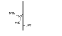
- the screen image creation unit 102 Using the read basic screen and the attached information, the protruding portion is inclined at a predetermined angle (for example, 80 degrees) with respect to the main screen so that the private information is not easily seen by anyone other than the operator.
- An operation screen (screen image) in which the private information is displayed on the projecting portion is created (S7).
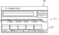
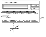
- the screen image creation unit 102 displays an example in FIGS. 7A and 7B. As shown, a screen having protrusions DF22a to DF22e inclined at a predetermined angle (for example, 80 degrees) with respect to the main screen DF21, and displaying the private information on the protrusions DF22a to DF22e An image DF2 is created.
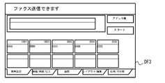
- FIG. 7C shows an example of the screen image DF3 in which no protrusion is formed.
- the screen image creation unit 102 forms a visible image in the above-described three-dimensional region in the XYZ directions in the air with respect to the protrusions DF22a to DF22e portions that display private information, and the angle with respect to the main screen is A screen image having a predetermined angle is created. At this time, the screen image creation unit 102 creates a screen image so that private information is displayed on the upper surfaces of the protrusions DF22a to DF22e.
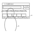
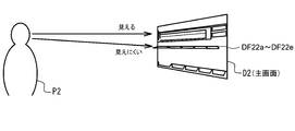
- the control unit 100 uses the screen image DF2 created as described above by the visible image forming unit 50 to display the visible image D2 in the air as illustrated in FIGS. 8, 9A, and 9B. Is formed (S8). At this time, the control unit 100 determines that the visible image forming unit 50 has a standard height in which the protrusions DF22a to DF22e are located close to the front of the visible image D2, as shown in FIG. 9A.
- the visible image D is formed at a spatial position below the height position of the eye line of the operator P1. As shown in FIG.
- the screen image creation unit 102 determines whether there is an overlap in the X direction based on the X coordinate information of each protrusion. If it is determined that there is an overlap in the X direction, the position of one overlapping protrusion is changed in the Z direction as shown in FIG. 10B to create a screen image.
- the screen image creation unit 102 calculates the overlapping length L in the Z direction based on the Z coordinate information of both of the projecting portions that overlap in the X direction, and then uses the Y coordinate information of the both. Based on the vertical relationship between the two, the lower protrusion is separated from the main screen by a length L or more in the Z direction. For example, the protrusions DF22a and DF22f as shown in FIG. A screen image DF4 arranged in the above is created.
- the screen image creation unit 102 uses the read basic screen. Then, an operation screen (screen image) that does not have the three-dimensional protrusion is created (S9).
- the control unit 100 causes the visible image forming unit 50 to form a visible image in the air using the screen image created by the screen image creating unit 102 (S6).
- the protrusions DF22a to DF22e that are inclined at the predetermined angle with respect to the main screen DF21 are created, and the protrusion Since a visible image of the operation screen DF2 on which the private information is displayed is formed on the upper surface portions of the parts DF22a to DF22e, the protrusions DF22a to DF22e are provided to the operator P located near the front of the operation screen DF2. In addition to making it easier to see, it is possible to make the operation screen DF2 on which the private information is displayed less visible to those who are farther away from the operation screen DF2 than the operator P.
- the inclination angle of the protrusion with respect to the main screen is not constant, and the angle may be changed according to the importance of private information.
- the screen image creation unit 102 creates a screen image by setting the angle as 90 degrees for personal information of the type that is used at the time of login, and setting the angle as 90 degrees for address information. Also good.
- the angle is 90 degrees because the importance is the highest, the operator P has difficulty in seeing the upper surfaces of the protrusions DF22a to DF22e unless the operator P further approaches the operation screen DF2.
- the private information displayed on the upper surfaces of the protrusions DF22a to DF22e can be made less visible.
- the present invention is not limited to the configuration of the above embodiment, and various modifications can be made.
- the visible image forming apparatus is applied to the image forming apparatus 1 in the above embodiment, the visible image forming apparatus can be widely applied to electronic devices other than the image forming apparatus 1. .
Landscapes
- Engineering & Computer Science (AREA)
- Physics & Mathematics (AREA)
- General Physics & Mathematics (AREA)
- Computer Hardware Design (AREA)
- Theoretical Computer Science (AREA)
- Multimedia (AREA)
- Signal Processing (AREA)
- Microelectronics & Electronic Packaging (AREA)
- Optics & Photonics (AREA)
- Facsimiles In General (AREA)
- Controls And Circuits For Display Device (AREA)
- Control Or Security For Electrophotography (AREA)
- Accessory Devices And Overall Control Thereof (AREA)
Abstract
Description
画面画像を作成する画面画像作成部と、
前記画面画像作成部により作成された画面画像の可視像を前記可視像形成部により形成させる制御部と、を備え、
前記可視像に予め定められた私的情報が含まれる場合、前記画面画像作成部は、当該私的情報をその主画面に対して、当該私的情報が操作者以外から見えにくくなる予め定められた角度で傾斜させた画面画像を作成し、前記制御部は、当該作成された画面画像の可視像を前記可視像形成部により形成させるものである。
前記制御部が、前記画像形成部についての指示を受け付けるための操作画面を前記画面画像作成部に作成させ、前記可視像形成部に当該操作画面の可視像を空中に形成させる上記可視像形成装置と、を備える。
Claims (6)
- 空中に可視像を形成する可視像形成部と、
画面画像を作成する画面画像作成部と、
前記画面画像作成部により作成された画面画像の可視像を前記可視像形成部により形成させる制御部と、を備え、
前記可視像に予め定められた私的情報が含まれる場合、前記画面画像作成部は、当該私的情報をその主画面に対して、当該私的情報が操作者以外から見えにくくなる予め定められた角度で傾斜させた画面画像を作成し、前記制御部は、当該作成された画面画像の可視像を前記可視像形成部により形成させる可視像形成装置。 - 前記画面画像作成部は、前記私的情報を示す前記画面画像部分のみを、前記私的情報を示す前記画面画像部分以外となる主画面部分に対して前記予め定められた角度で傾斜して前記主画面部分から突出させた前記画面画像を作成し、
前記制御部は、前記主画面部分を、前記可視像形成装置が設置されている地面に対して垂直方向に近い角度として、前記可視像形成部に前記画面画像の可視像を形成させる請求項1に記載の可視像形成装置。 - 前記画面画像作成部は、前記私的情報を示す前記画面画像部分を、前記主画面部分に対して前記予め定められた角度で傾斜させて複数作成するとき、前記垂直方向において、前記主画面部分から突出する部分同士が重ならない位置に、前記私的情報を示す前記画面画像部分のそれぞれを配置して、前記画面画像を作成する請求項2に記載の可視像形成装置。
- 前記画面画像を主画面に対して傾ける角度は、当該私的情報の重要度に応じて変更して設定されている請求項1に記載の可視像形成装置。
- 前記画面画像作成部は、前記画面画像を主画面に対して、複数の当該私的情報を示す画像部分を、操作者の視認方向においてずらした位置に配置した画面画像を作成し、前記制御部は、当該作成された画面画像の可視像を前記可視像形成部により空中に形成させる請求項1に記載の可視像形成装置。
- 記録媒体に画像形成を行う画像形成部と、
前記制御部が、前記画像形成部についての指示を受け付けるための操作画面を前記画面画像作成部に作成させ、前記可視像形成部に当該操作画面の可視像を空中に形成させる請求項1に記載の可視像形成装置と、を備える画像形成装置。
Priority Applications (4)
| Application Number | Priority Date | Filing Date | Title |
|---|---|---|---|
| JP2017507590A JP6399207B2 (ja) | 2015-03-26 | 2016-02-12 | 可視像形成装置及び画像形成装置 |
| CN201680013352.8A CN107408372B (zh) | 2015-03-26 | 2016-02-12 | 可视像形成装置以及图像形成装置 |
| EP16768212.9A EP3276608A4 (en) | 2015-03-26 | 2016-02-12 | Visible-image formation device and image formation device |
| US15/553,364 US9972231B1 (en) | 2015-03-26 | 2016-02-12 | Visible image forming apparatus and image forming apparatus |
Applications Claiming Priority (2)
| Application Number | Priority Date | Filing Date | Title |
|---|---|---|---|
| JP2015-064989 | 2015-03-26 | ||
| JP2015064989 | 2015-03-26 |
Publications (1)
| Publication Number | Publication Date |
|---|---|
| WO2016152309A1 true WO2016152309A1 (ja) | 2016-09-29 |
Family
ID=56978022
Family Applications (1)
| Application Number | Title | Priority Date | Filing Date |
|---|---|---|---|
| PCT/JP2016/054175 Ceased WO2016152309A1 (ja) | 2015-03-26 | 2016-02-12 | 可視像形成装置及び画像形成装置 |
Country Status (5)
| Country | Link |
|---|---|
| US (1) | US9972231B1 (ja) |
| EP (1) | EP3276608A4 (ja) |
| JP (1) | JP6399207B2 (ja) |
| CN (1) | CN107408372B (ja) |
| WO (1) | WO2016152309A1 (ja) |
Cited By (1)
| Publication number | Priority date | Publication date | Assignee | Title |
|---|---|---|---|---|
| JP2020514820A (ja) * | 2017-03-17 | 2020-05-21 | アリオスコピーAlioscopy | デジタル画像または一連のデジタル画像、特に自動立体化画像または一連の自動立体化画像における非物質化された架空の投影のための装置 |
Families Citing this family (5)
| Publication number | Priority date | Publication date | Assignee | Title |
|---|---|---|---|---|
| JP2018092045A (ja) * | 2016-12-05 | 2018-06-14 | キヤノン株式会社 | 画像形成装置 |
| JP6851191B2 (ja) * | 2016-12-15 | 2021-03-31 | キヤノン株式会社 | 情報処理システム、情報処理装置、その制御方法とプログラム |
| JP7119398B2 (ja) * | 2018-02-06 | 2022-08-17 | 富士フイルムビジネスイノベーション株式会社 | 情報処理装置及びプログラム |
| JP7128720B2 (ja) * | 2018-10-25 | 2022-08-31 | 日立チャネルソリューションズ株式会社 | 入出力装置及び自動取引装置 |
| CN113282174B (zh) * | 2021-05-27 | 2023-10-17 | 中国联合网络通信集团有限公司 | 终端信息显示方法、装置、终端及存储介质 |
Citations (3)
| Publication number | Priority date | Publication date | Assignee | Title |
|---|---|---|---|---|
| JP2009162834A (ja) * | 2007-12-28 | 2009-07-23 | Sharp Corp | 画像形成装置 |
| JP2010078623A (ja) * | 2008-09-23 | 2010-04-08 | Denso Corp | 車室内空中表示装置 |
| JP2016048347A (ja) * | 2014-08-28 | 2016-04-07 | エヌカント株式会社 | 情報表示システム |
Family Cites Families (6)
| Publication number | Priority date | Publication date | Assignee | Title |
|---|---|---|---|---|
| JP3650811B2 (ja) | 2002-02-13 | 2005-05-25 | 株式会社トプコン | 空中可視像形成装置 |
| JP4773222B2 (ja) | 2006-02-06 | 2011-09-14 | 独立行政法人産業技術総合研究所 | 空中可視像形成装置および空中可視像形成方法 |
| JP4821439B2 (ja) * | 2006-05-30 | 2011-11-24 | コニカミノルタビジネステクノロジーズ株式会社 | 画像形成装置 |
| US20100066662A1 (en) * | 2006-10-02 | 2010-03-18 | Pioneer Corporation | Image display device |
| WO2009131128A1 (ja) | 2008-04-22 | 2009-10-29 | Fujishima Tomohiko | 光学結像装置及びそれを用いた光学結像方法 |
| JP5444824B2 (ja) * | 2009-05-01 | 2014-03-19 | コニカミノルタ株式会社 | 画像形成装置 |
-
2016
- 2016-02-12 WO PCT/JP2016/054175 patent/WO2016152309A1/ja not_active Ceased
- 2016-02-12 JP JP2017507590A patent/JP6399207B2/ja not_active Expired - Fee Related
- 2016-02-12 CN CN201680013352.8A patent/CN107408372B/zh not_active Expired - Fee Related
- 2016-02-12 US US15/553,364 patent/US9972231B1/en active Active
- 2016-02-12 EP EP16768212.9A patent/EP3276608A4/en not_active Withdrawn
Patent Citations (3)
| Publication number | Priority date | Publication date | Assignee | Title |
|---|---|---|---|---|
| JP2009162834A (ja) * | 2007-12-28 | 2009-07-23 | Sharp Corp | 画像形成装置 |
| JP2010078623A (ja) * | 2008-09-23 | 2010-04-08 | Denso Corp | 車室内空中表示装置 |
| JP2016048347A (ja) * | 2014-08-28 | 2016-04-07 | エヌカント株式会社 | 情報表示システム |
Non-Patent Citations (1)
| Title |
|---|
| See also references of EP3276608A4 * |
Cited By (1)
| Publication number | Priority date | Publication date | Assignee | Title |
|---|---|---|---|---|
| JP2020514820A (ja) * | 2017-03-17 | 2020-05-21 | アリオスコピーAlioscopy | デジタル画像または一連のデジタル画像、特に自動立体化画像または一連の自動立体化画像における非物質化された架空の投影のための装置 |
Also Published As
| Publication number | Publication date |
|---|---|
| CN107408372B (zh) | 2019-10-25 |
| JPWO2016152309A1 (ja) | 2018-02-01 |
| CN107408372A (zh) | 2017-11-28 |
| EP3276608A4 (en) | 2018-10-24 |
| US20180137794A1 (en) | 2018-05-17 |
| JP6399207B2 (ja) | 2018-10-03 |
| US9972231B1 (en) | 2018-05-15 |
| EP3276608A1 (en) | 2018-01-31 |
Similar Documents
| Publication | Publication Date | Title |
|---|---|---|
| JP6399207B2 (ja) | 可視像形成装置及び画像形成装置 | |
| CN104079748B (zh) | 作业信息显示装置 | |
| JP5574854B2 (ja) | 情報処理システム、情報処理装置、情報処理方法及びプログラム | |
| WO2022018926A1 (ja) | 入力装置および入力装置の制御方法 | |
| JP6350360B2 (ja) | 可視像形成装置及び画像形成装置 | |
| JP6281520B2 (ja) | 画像形成装置 | |
| JP2006126229A (ja) | 表示装置、画像形成装置 | |
| US10692399B2 (en) | Braille tactile sensation presenting device and image forming apparatus | |
| JP6365767B2 (ja) | 可視像形成装置及び画像形成装置 | |
| WO2016152300A1 (ja) | 情報処理装置 | |
| JP2020014123A (ja) | 画像処理装置及びプログラム | |
| JP6299632B2 (ja) | 可視像形成装置を備える画像形成装置 | |
| JP2016184222A (ja) | 可視像形成装置及び画像形成装置 | |
| JP2021193780A (ja) | 画像読み取り装置、画像読み取り方法、及び画像読み取りプログラム | |
| JP6350386B2 (ja) | 可視像形成装置及び画像形成装置 | |
| JP2016162111A (ja) | 可視像形成装置及び画像形成装置 | |
| JP6394800B2 (ja) | 画像形成装置 | |
| US20130057914A1 (en) | Image forming apparatus and non-transitory computer readable recording medium stored with control program for image forming apparatus | |
| JP2016189144A (ja) | 可視像形成装置及び画像形成装置 | |
| JP2020120230A (ja) | 画像読取装置 | |
| JP4619960B2 (ja) | 印刷装置 | |
| WO2024023922A1 (ja) | 仮想空間画像生成方法および仮想空間画像生成システム | |
| JP2019149634A (ja) | 画像形成装置、表示制御方法およびプログラム | |
| JP2020119158A (ja) | 画像読取装置 | |
| JP2010193123A (ja) | スキャナ装置 |
Legal Events
| Date | Code | Title | Description |
|---|---|---|---|
| 121 | Ep: the epo has been informed by wipo that ep was designated in this application |
Ref document number: 16768212 Country of ref document: EP Kind code of ref document: A1 |
|
| ENP | Entry into the national phase |
Ref document number: 2017507590 Country of ref document: JP Kind code of ref document: A |
|
| WWE | Wipo information: entry into national phase |
Ref document number: 15553364 Country of ref document: US |
|
| REEP | Request for entry into the european phase |
Ref document number: 2016768212 Country of ref document: EP |
|
| NENP | Non-entry into the national phase |
Ref country code: DE |