WO2016152924A1 - 電気化学反応単位および燃料電池スタック - Google Patents
電気化学反応単位および燃料電池スタック Download PDFInfo
- Publication number
- WO2016152924A1 WO2016152924A1 PCT/JP2016/059215 JP2016059215W WO2016152924A1 WO 2016152924 A1 WO2016152924 A1 WO 2016152924A1 JP 2016059215 W JP2016059215 W JP 2016059215W WO 2016152924 A1 WO2016152924 A1 WO 2016152924A1
- Authority
- WO
- WIPO (PCT)
- Prior art keywords
- air electrode
- bonding layer
- current collector
- electrochemical reaction
- reaction unit
- Prior art date
- Legal status (The legal status is an assumption and is not a legal conclusion. Google has not performed a legal analysis and makes no representation as to the accuracy of the status listed.)
- Ceased
Links
Images


Classifications
-
- H—ELECTRICITY
- H01—ELECTRIC ELEMENTS
- H01M—PROCESSES OR MEANS, e.g. BATTERIES, FOR THE DIRECT CONVERSION OF CHEMICAL ENERGY INTO ELECTRICAL ENERGY
- H01M8/00—Fuel cells; Manufacture thereof
- H01M8/02—Details
- H01M8/0202—Collectors; Separators, e.g. bipolar separators; Interconnectors
- H01M8/0204—Non-porous and characterised by the material
- H01M8/0223—Composites
- H01M8/0228—Composites in the form of layered or coated products
-
- H—ELECTRICITY
- H01—ELECTRIC ELEMENTS
- H01M—PROCESSES OR MEANS, e.g. BATTERIES, FOR THE DIRECT CONVERSION OF CHEMICAL ENERGY INTO ELECTRICAL ENERGY
- H01M8/00—Fuel cells; Manufacture thereof
- H01M8/02—Details
- H01M8/0202—Collectors; Separators, e.g. bipolar separators; Interconnectors
- H01M8/0247—Collectors; Separators, e.g. bipolar separators; Interconnectors characterised by the form
-
- C—CHEMISTRY; METALLURGY
- C25—ELECTROLYTIC OR ELECTROPHORETIC PROCESSES; APPARATUS THEREFOR
- C25B—ELECTROLYTIC OR ELECTROPHORETIC PROCESSES FOR THE PRODUCTION OF COMPOUNDS OR NON-METALS; APPARATUS THEREFOR
- C25B1/00—Electrolytic production of inorganic compounds or non-metals
- C25B1/01—Products
- C25B1/02—Hydrogen or oxygen
- C25B1/04—Hydrogen or oxygen by electrolysis of water
-
- C—CHEMISTRY; METALLURGY
- C25—ELECTROLYTIC OR ELECTROPHORETIC PROCESSES; APPARATUS THEREFOR
- C25B—ELECTROLYTIC OR ELECTROPHORETIC PROCESSES FOR THE PRODUCTION OF COMPOUNDS OR NON-METALS; APPARATUS THEREFOR
- C25B11/00—Electrodes; Manufacture thereof not otherwise provided for
- C25B11/02—Electrodes; Manufacture thereof not otherwise provided for characterised by shape or form
-
- C—CHEMISTRY; METALLURGY
- C25—ELECTROLYTIC OR ELECTROPHORETIC PROCESSES; APPARATUS THEREFOR
- C25B—ELECTROLYTIC OR ELECTROPHORETIC PROCESSES FOR THE PRODUCTION OF COMPOUNDS OR NON-METALS; APPARATUS THEREFOR
- C25B13/00—Diaphragms; Spacing elements
- C25B13/04—Diaphragms; Spacing elements characterised by the material
- C25B13/05—Diaphragms; Spacing elements characterised by the material based on inorganic materials
-
- H—ELECTRICITY
- H01—ELECTRIC ELEMENTS
- H01M—PROCESSES OR MEANS, e.g. BATTERIES, FOR THE DIRECT CONVERSION OF CHEMICAL ENERGY INTO ELECTRICAL ENERGY
- H01M8/00—Fuel cells; Manufacture thereof
- H01M8/02—Details
-
- H—ELECTRICITY
- H01—ELECTRIC ELEMENTS
- H01M—PROCESSES OR MEANS, e.g. BATTERIES, FOR THE DIRECT CONVERSION OF CHEMICAL ENERGY INTO ELECTRICAL ENERGY
- H01M8/00—Fuel cells; Manufacture thereof
- H01M8/02—Details
- H01M8/0202—Collectors; Separators, e.g. bipolar separators; Interconnectors
-
- H—ELECTRICITY
- H01—ELECTRIC ELEMENTS
- H01M—PROCESSES OR MEANS, e.g. BATTERIES, FOR THE DIRECT CONVERSION OF CHEMICAL ENERGY INTO ELECTRICAL ENERGY
- H01M8/00—Fuel cells; Manufacture thereof
- H01M8/02—Details
- H01M8/0202—Collectors; Separators, e.g. bipolar separators; Interconnectors
- H01M8/023—Porous and characterised by the material
- H01M8/0241—Composites
- H01M8/0245—Composites in the form of layered or coated products
-
- H—ELECTRICITY
- H01—ELECTRIC ELEMENTS
- H01M—PROCESSES OR MEANS, e.g. BATTERIES, FOR THE DIRECT CONVERSION OF CHEMICAL ENERGY INTO ELECTRICAL ENERGY
- H01M8/00—Fuel cells; Manufacture thereof
- H01M8/10—Fuel cells with solid electrolytes
- H01M8/12—Fuel cells with solid electrolytes operating at high temperature, e.g. with stabilised ZrO2 electrolyte
- H01M8/124—Fuel cells with solid electrolytes operating at high temperature, e.g. with stabilised ZrO2 electrolyte characterised by the process of manufacturing or by the material of the electrolyte
- H01M8/1246—Fuel cells with solid electrolytes operating at high temperature, e.g. with stabilised ZrO2 electrolyte characterised by the process of manufacturing or by the material of the electrolyte the electrolyte consisting of oxides
-
- H—ELECTRICITY
- H01—ELECTRIC ELEMENTS
- H01M—PROCESSES OR MEANS, e.g. BATTERIES, FOR THE DIRECT CONVERSION OF CHEMICAL ENERGY INTO ELECTRICAL ENERGY
- H01M8/00—Fuel cells; Manufacture thereof
- H01M8/24—Grouping of fuel cells, e.g. stacking of fuel cells
-
- H—ELECTRICITY
- H01—ELECTRIC ELEMENTS
- H01M—PROCESSES OR MEANS, e.g. BATTERIES, FOR THE DIRECT CONVERSION OF CHEMICAL ENERGY INTO ELECTRICAL ENERGY
- H01M8/00—Fuel cells; Manufacture thereof
- H01M8/24—Grouping of fuel cells, e.g. stacking of fuel cells
- H01M8/241—Grouping of fuel cells, e.g. stacking of fuel cells with solid or matrix-supported electrolytes
- H01M8/2425—High-temperature cells with solid electrolytes
-
- H—ELECTRICITY
- H01—ELECTRIC ELEMENTS
- H01M—PROCESSES OR MEANS, e.g. BATTERIES, FOR THE DIRECT CONVERSION OF CHEMICAL ENERGY INTO ELECTRICAL ENERGY
- H01M8/00—Fuel cells; Manufacture thereof
- H01M8/10—Fuel cells with solid electrolytes
- H01M8/12—Fuel cells with solid electrolytes operating at high temperature, e.g. with stabilised ZrO2 electrolyte
- H01M2008/1293—Fuel cells with solid oxide electrolytes
-
- Y—GENERAL TAGGING OF NEW TECHNOLOGICAL DEVELOPMENTS; GENERAL TAGGING OF CROSS-SECTIONAL TECHNOLOGIES SPANNING OVER SEVERAL SECTIONS OF THE IPC; TECHNICAL SUBJECTS COVERED BY FORMER USPC CROSS-REFERENCE ART COLLECTIONS [XRACs] AND DIGESTS
- Y02—TECHNOLOGIES OR APPLICATIONS FOR MITIGATION OR ADAPTATION AGAINST CLIMATE CHANGE
- Y02E—REDUCTION OF GREENHOUSE GAS [GHG] EMISSIONS, RELATED TO ENERGY GENERATION, TRANSMISSION OR DISTRIBUTION
- Y02E60/00—Enabling technologies; Technologies with a potential or indirect contribution to GHG emissions mitigation
- Y02E60/30—Hydrogen technology
- Y02E60/36—Hydrogen production from non-carbon containing sources, e.g. by water electrolysis
-
- Y—GENERAL TAGGING OF NEW TECHNOLOGICAL DEVELOPMENTS; GENERAL TAGGING OF CROSS-SECTIONAL TECHNOLOGIES SPANNING OVER SEVERAL SECTIONS OF THE IPC; TECHNICAL SUBJECTS COVERED BY FORMER USPC CROSS-REFERENCE ART COLLECTIONS [XRACs] AND DIGESTS
- Y02—TECHNOLOGIES OR APPLICATIONS FOR MITIGATION OR ADAPTATION AGAINST CLIMATE CHANGE
- Y02E—REDUCTION OF GREENHOUSE GAS [GHG] EMISSIONS, RELATED TO ENERGY GENERATION, TRANSMISSION OR DISTRIBUTION
- Y02E60/00—Enabling technologies; Technologies with a potential or indirect contribution to GHG emissions mitigation
- Y02E60/30—Hydrogen technology
- Y02E60/50—Fuel cells
-
- Y—GENERAL TAGGING OF NEW TECHNOLOGICAL DEVELOPMENTS; GENERAL TAGGING OF CROSS-SECTIONAL TECHNOLOGIES SPANNING OVER SEVERAL SECTIONS OF THE IPC; TECHNICAL SUBJECTS COVERED BY FORMER USPC CROSS-REFERENCE ART COLLECTIONS [XRACs] AND DIGESTS
- Y02—TECHNOLOGIES OR APPLICATIONS FOR MITIGATION OR ADAPTATION AGAINST CLIMATE CHANGE
- Y02P—CLIMATE CHANGE MITIGATION TECHNOLOGIES IN THE PRODUCTION OR PROCESSING OF GOODS
- Y02P70/00—Climate change mitigation technologies in the production process for final industrial or consumer products
- Y02P70/50—Manufacturing or production processes characterised by the final manufactured product
Definitions
- the technology disclosed by this specification relates to an electrochemical reaction unit.
- a fuel cell power generation unit (hereinafter also simply referred to as “power generation unit”), which is the minimum unit of SOFC power generation, includes a single cell including an electrolyte layer and an air electrode and a fuel electrode facing each other across the electrolyte layer, and a single cell In order to collect the electric power generated in step 1, a conductive current collecting member disposed on each of the air electrode side and the fuel electrode side of the single cell is provided.
- positioned at the air electrode side of a single cell has a protrusion part which protrudes toward an air electrode.
- the air electrode and the current collecting member are electrically connected to each other by joining the air electrode and the protruding portion of the current collecting member with a conductive joining layer.
- the current collecting member disposed on the air electrode side of the single cell is formed of a metal containing Cr (chromium) such as ferritic stainless steel, for example.
- Cr chromium
- Cr diffusion a phenomenon called “Cr diffusion” in which Cr is released from the surface of the current collecting member and diffuses. May occur.
- Cr released from the current collector enters the inside of the bonding layer, Cr reacts with the components of the bonding layer to cause a decrease in the conductivity of the bonding layer, or Cr passes through the bonding layer and interfaces with the air electrode.
- the corner portion of the protruding portion of the current collecting member has more surfaces than the portion other than the corner portion of the protruding portion. Moreover, the thickness of the coat covering the protruding portion is likely to be thin at the corner position of the protruding portion. Therefore, Cr diffusion is more likely to occur at the corners of the protruding portion of the current collecting member than at portions other than the corners of the protruding portion. Therefore, in the vicinity of the corner of the protruding portion of the current collecting member, Cr released from the protruding portion tends to enter the inside of the bonding layer, so that the conductivity of the bonding layer and the electrode reaction rate of the air electrode are likely to decrease.
- the above-described conventional technology has a problem that such a decrease in the conductivity of the bonding layer and a decrease in the electrode reaction rate of the air electrode cannot be sufficiently suppressed.
- electrolytic cell unit which is the minimum unit of a solid oxide electrolytic cell (hereinafter also referred to as “SOEC”) that generates hydrogen by utilizing an electrolysis reaction of water. It is a problem.
- SOEC solid oxide electrolytic cell
- the power generation unit and the electrolysis cell unit are collectively referred to as an electrochemical reaction unit.
- An electrochemical reaction unit disclosed in the present specification includes an electrolyte layer including a solid oxide, and an air electrode and a fuel electrode facing each other in a first direction with the electrolyte layer interposed therebetween.
- a current collecting member that is disposed on the air electrode side of the single cell and has a protruding portion that protrudes toward the air electrode, a conductive coat that covers a surface of the current collecting member, and a cover that covers the coat.
- An electrochemical reaction unit comprising a conductive bonding layer for bonding the protruding portion and the air electrode, and covering the coat in at least one cross section parallel to the first direction of the protruding portion.
- the broken protrusion has a covering portion covered with the bonding layer, and an exposed portion exposed from the bonding layer, including a corner portion of the protruding portion covered with the coat. It is characterized by that.
- Cr released from the corners of the protruding portion of the current collecting member where the surface is large and the coat tends to be thin and thus Cr is likely to be released enters the inside of the bonding layer. And the occurrence of a decrease in the conductivity of the bonding layer and a decrease in the electrode reaction rate of the air electrode can be effectively suppressed.
- the protrusion covered with the coat includes the covering portion and the exposed portion. Also good. According to the present electrochemical reaction unit, Cr released from the corners of the protruding portion of the current collecting member can be more effectively suppressed from entering the inside of the bonding layer, and the conductivity of the bonding layer can be reduced. Generation
- production of the electrode reaction rate fall of an air electrode can be suppressed more effectively.
- the contact area of the bonding layer with the air electrode may be smaller than the contact area of the bonding layer with the protrusion covered with the coat. According to the present electrochemical reaction unit, it is possible to suppress the gas diffusion into the air electrode from being inhibited by the bonding layer, and thus it is possible to suppress a decrease in power generation performance.
- the contact area of the bonding layer with the air electrode may be larger than the contact area of the bonding layer with the protrusion covered with the coat. According to this electrochemical reaction unit, the contact area between the bonding layer and the air electrode can be increased, and the decrease in conductivity of the bonding layer can be more effectively suppressed. Moreover, according to this electrochemical reaction unit, the reaction interface which receives the electron of an air electrode becomes large, and electric power generation performance can be improved.
- the bonding layer may be formed of a spinel oxide. According to this electrochemical reaction unit, even if Cr released from the corners of the protrusions enters the bonding layer, the bonding layer is compared with a configuration in which the bonding layer is formed of another material such as a perovskite oxide. Since the degree of increase in the resistance value due to the influence can be suppressed to a low level, it is possible to more effectively suppress the decrease in the conductivity of the bonding layer.
- a fuel cell power generation unit a fuel cell stack including a plurality of fuel cell power generation units, and a power generation module including a fuel cell stack
- a fuel cell system including a power generation module, an electrolytic cell unit, an electrolytic cell stack including a plurality of electrolytic cell units, a hydrogen generation module including an electrolytic cell stack, a hydrogen generation system including a hydrogen generation module, etc. It is.
- FIG. 1 is an external perspective view schematically showing a configuration of a fuel cell stack 100.
- FIG. It is explanatory drawing (XZ sectional drawing) which shows the structure of the electric power generation unit 102 roughly. It is explanatory drawing (YZ sectional drawing) which shows the structure of the electric power generation unit 102 roughly. It is explanatory drawing (XY sectional drawing) which shows the structure of the electric power generation unit 102 roughly. It is explanatory drawing (XY sectional drawing) which shows the structure of the electric power generation unit 102 roughly. It is explanatory drawing (XY sectional drawing) which shows the structure of the electric power generation unit 102 roughly.
- FIG. 5 is an explanatory view showing a configuration around an air electrode side current collector 134. It is explanatory drawing which shows the structure around the air electrode side collector 134 in 2nd Embodiment.
- FIG. 16 is an explanatory diagram showing a detailed configuration of a current collector 20 in a fuel cell stack of another modification shown in FIGS. 14 and 15.
- FIG. 16 is an explanatory diagram showing a detailed configuration of a current collector 20 in a fuel cell stack of another modification shown in FIGS. 14 and 15.
- FIG. 1 is an external perspective view schematically showing the configuration of the fuel cell stack 100.
- FIG. 1 shows XYZ axes orthogonal to each other for specifying the direction.
- the positive direction of the Z axis is referred to as the upward direction
- the negative direction of the Z axis is referred to as the downward direction.
- the fuel cell stack 100 is installed in a direction different from such a direction. Also good. The same applies to FIG.
- the fuel cell stack 100 includes a plurality of fuel cell power generation units (hereinafter also simply referred to as “power generation units”) 102 arranged in a predetermined arrangement direction (vertical direction in the present embodiment) and a plurality of power generation units 102. And a pair of end plates 104 and 106 arranged so as to be sandwiched between them.
- the number of power generation units 102 included in the fuel cell stack 100 shown in FIG. 1 is merely an example, and the number of power generation units 102 is appropriately determined according to the output voltage required for the fuel cell stack 100 or the like.
- the arrangement direction (vertical direction) corresponds to the first direction.
- a plurality of (eight in the present embodiment) through-holes 108 extending in the vertical direction from the upper end plate 104 to the lower end plate 106 are formed in the peripheral portion around the Z direction of the fuel cell stack 100.
- the layers constituting the fuel cell stack 100 are fastened and fixed by bolts 22 inserted into the through holes 108 and nuts 24 fitted to the bolts 22.
- Bolt 22 (bolt 22A) and through-hole located near the midpoint of one side (the two sides parallel to the Y-axis on the X-axis positive direction side) on the outer periphery around the Z-direction of the fuel cell stack 100 108 functions as an oxidant gas supply manifold 161 that supplies an oxidant gas (represented as “OG” in each figure) to each power generation unit 102, and a side opposite to the side (Y-axis)
- the space formed by the bolt 22 (bolt 22B) and the through-hole 108 located near the midpoint of the two sides parallel to the X-axis negative direction side is unreacted from each power generation unit 102.
- oxidant off-gas oxidant gas
- OOG oxidant off-gas
- a bolt 22 located near the midpoint of the other side (the side on the Y-axis positive direction side of the two sides parallel to the X-axis) on the outer periphery around the Z-direction of the fuel cell stack 100;
- the space formed by the through-hole 108 functions as a fuel gas supply manifold 171 that supplies fuel gas (represented as “FG” in each figure) to each power generation unit 102, and the side opposite to the side (X-axis)
- the space formed by the bolt 22 (bolt 22E) and the through hole 108 located near the midpoint of the two sides parallel to the negative Y-axis side is unreacted from each power generation unit 102.
- fuel gas discharge manifold 172 that discharges fuel gas (hereinafter referred to as “fuel off-gas” and represented as “OFG” in each figure).
- fuel gas hereinafter referred to as “fuel off-gas” and represented as “OFG” in each figure.
- fuel gas hereinafter referred to as “fuel off-gas” and represented as “OFG” in each figure.
- air is used as the oxidant gas
- hydrogen-rich gas obtained by reforming for example, city gas is used as the fuel gas.
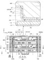
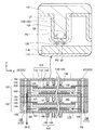
- FIG. 2 shows a cross-sectional configuration of the power generation unit 102 at the position II-II in FIGS. 1, 4 and 5, and FIG. 3 shows the position at III-III in FIGS. 4 shows a cross-sectional configuration of the power generation unit 102, FIG. 4 shows a cross-sectional configuration of the power generation unit 102 at the position IV-IV in FIG. 2, and FIG. 5 shows a position at VV in FIG.
- the cross-sectional structure of the power generation unit 102 in FIG. 2 and 3 are enlarged partial views.
- the power generation unit 102 that is the minimum unit of power generation includes a single cell 110, a separator 120, an air electrode side frame 130, an air electrode side current collector 134, and a fuel electrode side frame. 140, a fuel electrode side current collector 144, and a pair of interconnectors 150 constituting the uppermost layer and the lowermost layer of the power generation unit 102. Holes corresponding to the above-described through holes 108 into which the bolts 22 are inserted are formed in the periphery of the separator 120, the air electrode side frame 130, the fuel electrode side frame 140, and the interconnector 150 around the Z axis.
- the single cell 110 includes an electrolyte layer 112, and an air electrode 114 and a fuel electrode 116 that face each other in the vertical direction with the electrolyte layer 112 interposed therebetween.
- the single cell 110 of the present embodiment is a fuel electrode-supported single cell that supports the electrolyte layer 112 and the air electrode 114 with the fuel electrode 116.
- the electrolyte layer 112 is a rectangular flat plate member, such as YSZ (yttria stabilized zirconia), ScSZ (scandia stabilized zirconia), SDC (samarium doped ceria), GDC (gadolinium doped ceria), perovskite oxide, and the like.
- the solid oxide is formed.
- the air electrode 114 is a rectangular flat plate member smaller than the electrolyte layer 112 when viewed in the XY plane.
- the air electrode 114 is a perovskite oxide (for example, LSCF (lanthanum strontium cobalt iron oxide), LSM (lanthanum strontium manganese). Oxide), LNF (lanthanum nickel iron)).
- the fuel electrode 116 is a rectangular flat plate member having the same size as the electrolyte layer 112 when viewed in the XY plane.
- Ni nickel
- a cermet made of Ni and ceramic particles a Ni-based alloy, etc. It is formed by.
- the single cell 110 of this embodiment is a solid oxide fuel cell (SOFC) provided with the electrolyte layer 112 containing a solid oxide.
- SOFC solid oxide fuel cell
- the separator 120 is a frame-like member in which a square through hole 121 is formed near the center, and is made of, for example, metal.
- the peripheral portion of the separator 120 around the through hole 121 is opposed to the peripheral edge portion of the surface of the electrolyte layer 112 on the air electrode 114 side.
- the separator 120 is bonded to the electrolyte layer 112 (single cell 110) by a bonding portion 124 formed of a brazing material (for example, Ag brazing) disposed in the facing portion.
- the separator 120 divides the air chamber 166 facing the air electrode 114 and the fuel chamber 176 facing the fuel electrode 116, and suppresses gas leakage from one electrode side to the other electrode side.
- the single cell 110 to which the separator 120 is bonded is also referred to as a single cell with a separator.
- the air electrode side frame 130 is a frame-like member in which a rectangular through hole 131 is formed near the center, and is formed of an insulator such as mica, for example.
- the air electrode side frame 130 is in contact with the peripheral edge portion of the surface of the separator 120 opposite to the side facing the electrolyte layer 112 and the peripheral edge portion of the surface of the interconnector 150 facing the air electrode 114. .
- the air electrode side frame 130 secures an air chamber 166 between the air electrode 114 and the interconnector 150, and electrically isolates the pair of interconnectors 150 included in the power generation unit 102.
- the air electrode side frame 130 has an oxidant gas supply communication hole 132 communicating the oxidant gas supply manifold 161 and the air chamber 166, and an oxidant gas communicating the air chamber 166 and the oxidant gas discharge manifold 162.
- a discharge communication hole 133 is formed.
- the fuel electrode side frame 140 is a frame-like member in which a square through hole 141 is formed near the center, and is formed of, for example, metal.
- the fuel electrode side frame 140 is in contact with the peripheral portion of the surface of the separator 120 facing the electrolyte layer 112 and the peripheral portion of the surface of the interconnector 150 facing the fuel electrode 116.
- a fuel chamber 176 is secured between the fuel electrode 116 and the interconnector 150 by the fuel electrode side frame 140.
- the fuel electrode side frame 140 has a fuel gas supply communication hole 142 communicating with the fuel gas supply manifold 171 and the fuel chamber 176, and a fuel gas discharge communication hole 143 communicating with the fuel chamber 176 and the fuel gas discharge manifold 172. And are formed.
- the fuel electrode side current collector 144 is disposed in the fuel chamber 176.
- the fuel electrode side current collector 144 includes an interconnector facing portion 146, a plurality of electrode facing portions 145, and a connecting portion 147 that connects each electrode facing portion 145 and the interconnector facing portion 146. Or nickel alloy, stainless steel or the like.
- the fuel electrode side current collector 144 is manufactured by cutting a square flat plate member and bending a plurality of square portions. The bent rectangular portion becomes the electrode facing portion 145, the perforated flat plate portion other than the bent raised portion becomes the interconnector facing portion 146, and the portion connecting the electrode facing portion 145 and the interconnector facing portion 146 is connected. Part 147.
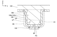
- the air electrode side current collector 134 is disposed in the air chamber 166.
- the air electrode side current collector 134 is composed of a plurality of rectangular columnar current collector elements 135, and is formed of a metal containing Cr (chromium) such as ferritic stainless steel, for example.
- the air electrode side current collector 134 is brought into contact with the surface of the air electrode 114 opposite to the side facing the electrolyte layer 112 and the surface of the interconnector 150 facing the air electrode 114, whereby the air electrode 114 and the interconnector 150 are electrically connected.
- the air electrode side current collector 134 and the interconnector 150 are formed as an integral member.
- a flat plate portion perpendicular to the vertical direction (Z-axis direction) of the integrated member functions as the interconnector 150 and is formed so as to protrude from the flat plate portion toward the air electrode 114.
- the plurality of current collector elements 135 function as the air electrode side current collector 134.
- the air electrode side current collector 134 or an integrated member of the air electrode side current collector 134 and the interconnector 150 is an example of a current collecting member.
- each current collector element 135 constituting the air electrode side current collector 134 is an example of a protruding portion that protrudes toward the air electrode 114.
- the surface of the air electrode side current collector 134 is covered with a conductive coat 136.
- the coat 136 is formed of a spinel oxide containing at least one of Zn (zinc), Mn (manganese), Co (cobalt), and Cu (copper) (for example, Mn 1.5 Co 1.5 O 4 or MnCo 2 O 4 , ZnCo 2 O 4 , ZnMnCoO 4 , CuMn 2 O 4 ).
- the coating 136 is formed on the surface of the air electrode side current collector 134 by a known method such as spray coating, ink jet printing, spin coating, dip coating, plating, sputtering, or thermal spraying.
- the air electrode side current collector 134 and the interconnector 150 are formed as an integral member. Therefore, in practice, the boundary surface with the interconnector 150 in the surface of the air electrode side current collector 134 is not covered with the coat 136, while at least the oxidizing gas flow path in the surface of the interconnector 150.
- the surface facing the surface that is, the surface on the air electrode 114 side of the interconnector 150 and the surface facing the through-hole 108 constituting the oxidant gas supply manifold 161 and the oxidant gas discharge manifold 162
- a chromium oxide film may be formed by heat treatment on the air electrode side current collector 134.
- the coat 136 is not the film but the air electrode side current collector 134 on which the film is formed. It is the layer formed so that it might cover.
- the air electrode side current collector 134 or current collector element 135) means “the air electrode side current collector 134 (or current collector element 135) covered with the coat 136”. To do.
- the air electrode 114 and the air electrode side current collector 134 are joined by a conductive joining layer 138.
- the bonding layer 138 includes a spinel oxide containing at least one of Zn, Mn, Co, and Cu (for example, Mn 1.5 Co 1.5 O 4 , MnCo 2 O 4 , ZnCo 2). O 4 , ZnMnCoO 4 , CuMn 2 O 4 ).
- the coat 136 and the bonding layer 138 are formed of spinel oxides whose main component elements are the same.
- the main component element here refers to a metal element constituting a spinel oxide.
- the identification of the spinel oxide can be realized by performing X-ray diffraction and elemental analysis.
- the bonding layer 138 is printed on a portion of the surface of the air electrode 114 facing the front end portion of each current collector element 135 constituting the air electrode side current collector 134. It is formed by firing under a predetermined condition in a state where the front end portion of the electric element 135 is pressed against the paste.
- the air electrode 114 and the air electrode side current collector 134 are electrically connected by the bonding layer 138. As described above, it is described that the air electrode side current collector 134 is in contact with the surface of the air electrode 114. To be precise, the air electrode side current collector 134 (covered by the coat 136), the air electrode 114, A bonding layer 138 is interposed therebetween.
- A-2. Power generation operation in the fuel cell stack 100 As shown in FIG. 2, when the oxidant gas OG is supplied to the oxidant gas supply manifold 161, the oxidant gas OG passes through the oxidant gas supply communication holes 132 of the power generation units 102 from the oxidant gas supply manifold 161. Then, the air is supplied to the air chamber 166. As shown in FIG. 3, when the fuel gas FG is supplied to the fuel gas supply manifold 171, the fuel gas FG passes through the fuel gas supply communication hole 142 of each power generation unit 102 from the fuel gas supply manifold 171 to the fuel gas FG. Supplied to chamber 176.
- each power generation unit 102 When the oxidant gas OG is supplied to the air chamber 166 of each power generation unit 102 and the fuel gas FG is supplied to the fuel chamber 176, power is generated by an electrochemical reaction between the oxidant gas OG and the fuel gas FG in the single cell 110. Is called.
- the air electrode 114 of the single cell 110 is electrically connected to one interconnector 150 through the air electrode side current collector 134 (and the coat 136, the bonding layer 138), and the fuel electrode 116 is a fuel. It is electrically connected to the other interconnector 150 via the pole side current collector 144.
- a plurality of power generation units 102 included in the fuel cell stack 100 are connected in series.
- each power generation unit 102 electrical energy generated in each power generation unit 102 is taken out from the end plates 104 and 106 that function as output terminals of the fuel cell stack 100. Since SOFC generates power at a relatively high temperature (for example, 700 to 1000 degrees Celsius), the fuel cell stack 100 is a heater until the high temperature can be maintained by the heat generated by power generation after startup. May be heated.
- SOFC generates power at a relatively high temperature (for example, 700 to 1000 degrees Celsius)
- the fuel cell stack 100 is a heater until the high temperature can be maintained by the heat generated by power generation after startup. May be heated.
- the oxidant off-gas OOG (oxidant gas not used for the power generation reaction in each power generation unit 102) passes through the oxidant gas discharge communication hole 133 and the oxidant gas discharge manifold 162 from the air chamber 166 as shown in FIG.
- the fuel cell stack 100 is discharged outside. Further, as shown in FIG. 3, the fuel off-gas OFG (fuel gas not used for the power generation reaction in each power generation unit 102) passes through the fuel gas discharge communication hole 143 and the fuel gas discharge manifold 172 from the fuel chamber 176. It is discharged outside the battery stack 100.
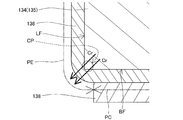
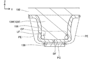
- the bonding layer 138 includes the air electrode 114 and the current collector element 135 in each cross section parallel to the vertical direction of each current collector element 135 constituting the air electrode side current collector 134. Exists in a region between a portion of the surface facing the air electrode 114 (hereinafter referred to as “bottom surface BF”), but extends outward (in a direction perpendicular to the vertical direction) from the region. Absent. That is, the current collector element 135 has a covering portion PC covered with the bonding layer 138 and an exposed portion PE that is not covered with the bonding layer 138 and is exposed from the bonding layer 138, and the exposed portion.
- the PE includes the corner CP of the current collector element 135.
- the corner CP of the current collector element 135 is not covered with the bonding layer 138.
- the corner portion CP of the current collector element 135 is located near the boundary between the bottom surface BF and the side surface LF in the form in which the bottom surface BF and the side surface LF are both a single plane as shown in FIGS. Part.
- the bonding layer 138 covers only the center portion of the bottom surface BF of the current collector element 135 and does not cover the peripheral edge portion, and does not cover the side surface LF of the current collector element 135, the current collector element 135 corner portions CP are not covered with the bonding layer 138.
- the corner CP of the current collector element 135 is covered with the bonding layer 138 in the same manner as the cross sections shown in FIGS. 2 and 3. Absent. That is, when viewed from the air electrode 114 side, the entire circumference of the corner CP of the current collector element 135 is not covered with the bonding layer 138. 2 and 3 show the configuration of a part of the current collector elements 135 constituting the air electrode side current collector 134. In this embodiment, the air electrode side current collector 134 is configured. Similarly, for all the current collector elements 135 to be performed, the entire circumference of the corner portion CP of the current collector element 135 is not covered with the bonding layer 138.
- each current collector element 135 constituting the air electrode side current collector 134 is covered with the coat 136.
- the current collector element 135 is a portion including the covering portion PC covered with the bonding layer 138 and the corner CP of the current collector element 135 and is not covered with the bonding layer 138 and is exposed from the bonding layer 138. And an exposed portion PE. That is, the entire circumference of the corner CP of each current collector element 135 is not covered with the bonding layer 138 and is not in contact with the bonding layer 138.
- the bonding layer 138 is formed of a spinel oxide, even if Cr released from the corner portion CP of the current collector element 135 enters the bonding layer 138, the bonding layer 138 is perovskite. Compared with the case of using another material such as a type oxide, the degree of increase in the resistance value due to the influence of Cr can be kept low, so that the conductivity of the bonding layer 138 can be more effectively reduced. Can be suppressed.
- the spinel oxide that is a material for forming the bonding layer 138 is a spinel oxide containing at least one of Zn, Mn, Co, and Cu.
- a spinel oxide containing at least one of Zn, Mn, Co, and Cu is a material that easily maintains a spinel structure even in a relatively high temperature environment for a long time. When the spinel oxide is used, the effect of suppressing the decrease in the conductivity of the bonding layer 138 can be maintained for a long time.
- the configuration of the bonding layer 138a is different from that of the first embodiment.
- the contact area of the bonding layer 138a with the air electrode 114 is larger than the contact area of the bonding layer 138a with the current collector element 135 (covered by the coat 136). Therefore, the contact area between the bonding layer 138a and the air electrode 114 can be increased, and the decrease in conductivity of the bonding layer 138a can be more effectively suppressed.
- the reaction interface contact interface with the bonding layer 138a
- the power generation performance can be improved.
- the current collector element 135 is the same in all cross sections parallel to the vertical direction of each current collector element 135 constituting the air electrode side current collector 134.
- a covering portion PC covered with the bonding layer 138a and an exposed portion PE which is a portion including the corner CP of the current collector element 135 and is not covered with the bonding layer 138a and exposed from the bonding layer 138a. ing. That is, the entire circumference of the corner CP of each current collector element 135 is not covered with the bonding layer 138a. Therefore, also in 2nd Embodiment, there exists the same effect as the effect of 1st Embodiment mentioned above.
- FIG. 8 is an explanatory diagram showing a configuration around the air electrode side current collector 134 in the third embodiment.
- FIG. 8 shows a cross-sectional configuration parallel to the Z-axis and the Y-axis for a portion around the air electrode side current collector 134.
- the same configurations as those of the first embodiment described above are denoted by the same reference numerals, and description thereof is omitted.
- the configuration of the bonding layer 138b is different from the first embodiment and the second embodiment. Specifically, in the third embodiment, the contact area of the bonding layer 138b with the air electrode 114 is smaller than the contact area of the bonding layer 138b with the current collector element 135 (covered by the coat 136). Therefore, since it can suppress that gas diffusion to the inside of the air electrode 114 is inhibited by the bonding layer 138b, a decrease in power generation performance can be suppressed.
- the current collector element 135 in all cross sections parallel to the vertical direction of each current collector element 135 constituting the air electrode side current collector 134, the current collector element 135 is A covering portion PC covered with the bonding layer 138b, and an exposed portion PE which is a portion including the corner portion CP of the current collector element 135 and is not covered with the bonding layer 138b and exposed from the bonding layer 138b. ing. That is, the entire circumference of the corner CP of each current collector element 135 is not covered with the bonding layer 138b. Therefore, also in 3rd Embodiment, there exists the same effect as the effect of 1st Embodiment mentioned above.
- FIG. 9 is an explanatory diagram showing a configuration around the air electrode side current collector 134c in a modified example.
- FIG. 9 shows a cross-sectional configuration parallel to the Z-axis and the Y-axis for a portion around the air electrode side current collector 134c. The same applies to FIGS. 10 to 13 described later.
- the protrusion BU exists on the side surface LF of the current collector element 135c constituting the air electrode side current collector 134c.
- the corner portion CP of the current collector element 135c is a portion near the boundary between the bottom surface BF and the side surface LF in the current collector element 135c.
- the body element 135c includes a covering portion PC covered with the bonding layer 138 and an exposed portion PE that is exposed from the bonding layer 138 without being covered with the bonding layer 138 and including the corner CP of the current collector element 135c. It can be said that it has.
- FIG. 10 is an explanatory diagram showing a configuration around the air electrode side current collector 134d in another modification.
- the side surface LF of the current collector element 135d constituting the air electrode side current collector 134d is not a flat surface but a curved surface.
- the vicinity of the boundary between the side surface LF of the current collector element 135d and the bottom surface BF is a curved surface protruding outward from the current collector element 135d.
- the corner portion CP of the current collector element 135d is a portion near the boundary between the bottom surface BF and the side surface LF in the current collector element 135d. In the configuration shown in FIG.
- FIG. 11 is an explanatory diagram showing a configuration around the air electrode side current collector 134e in another modification.
- the side surface LF of the current collector element 135e constituting the air electrode side current collector 134e is not a flat surface but a curved surface.
- the vicinity of the boundary between the side surface LF of the current collector element 135e and the bottom surface BF is a curved surface convex toward the inside of the current collector element 135e.
- the corner portion CP of the current collector element 135e is a portion near the boundary between the bottom surface BF and the side surface LF in the current collector element 135e. In the configuration shown in FIG.
- the bonding layer 138 covers only the central portion of the bottom surface BF of the current collector element 135e and does not cover the peripheral edge portion, and does not cover the side surface LF of the current collector element 135e.
- the body element 135e includes a covering portion PC covered with the bonding layer 138 and an exposed portion PE that is exposed from the bonding layer 138 without being covered with the bonding layer 138 and including the corner CP of the current collector element 135e. It can be said that it has.
- FIG. 12 is an explanatory view showing a configuration around the air electrode side current collector 134f in another modification.
- the side surface LF and the bottom surface BF of the current collector element 135f constituting the air electrode side current collector 134f are not flat surfaces but curved surfaces.
- the vicinity of the boundary with the bottom surface BF on the side surface LF of the current collector element 135f is a curved surface that protrudes inward of the current collector element 135f.
- the vicinity of the boundary with the side surface LF on the bottom surface BF of the current collector element 135f is a curved surface protruding outward from the current collector element 135f.
- the corner portion CP of the current collector element 135f is a portion near the boundary between the bottom surface BF and the side surface LF in the current collector element 135f.
- the bonding layer 138 covers only the central portion of the bottom surface BF of the current collector element 135f and does not cover the peripheral edge portion, and does not cover the side surface LF of the current collector element 135f.
- the body element 135f includes a covering portion PC covered with the bonding layer 138 and an exposed portion PE that is exposed from the bonding layer 138 without being covered by the bonding layer 138 and including the corner CP of the current collector element 135f. It can be said that it has.
- FIG. 13 is an explanatory diagram showing a configuration around the air electrode side current collector 134g in another modification.
- the bottom surface BF of the current collector element 135g constituting the air electrode side current collector 134g is not a flat surface but a curved surface.
- the bottom surface BF of the current collector element 135g is composed of one or a plurality of planes or curved surfaces, but forms a convex surface on the lower side as a whole.
- the corner portion CP of the current collector element 135g is a portion near the boundary between the bottom surface BF and the side surface LF in the current collector element 135g. In the configuration shown in FIG.
- the bonding layer 138 covers only the central portion of the bottom surface BF of the current collector element 135g and does not cover the peripheral edge portion, and does not cover the side surface LF of the current collector element 135g.
- the body element 135g is a portion including the covering portion PC covered with the bonding layer 138 and the corner CP of the current collector element 135g and is not covered with the bonding layer 138 and exposed from the bonding layer 138. It can be said that it has.
- the fuel cell stack 100 has a configuration in which a plurality of flat-plate power generation units 102 are stacked.
- the present invention is described in other configurations, for example, Japanese Patent Application Laid-Open No. 2008-59797.
- the present invention can be similarly applied to a configuration in which a plurality of substantially cylindrical fuel cell single cells are connected in series.
- FIG. 14 is an explanatory diagram schematically showing the configuration of the fuel cell stack in another modification
- FIG. 15 schematically shows the configuration of the fuel cell 1 constituting the fuel cell stack in another modification. It is explanatory drawing.
- the fuel cell stack in this modification includes a plurality of hollow plate fuel cells 1 and a current collector 20.
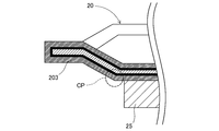
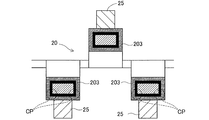
- 16 and 17 are explanatory views showing the detailed configuration of the current collector 20 in the fuel cell stack according to another modification shown in FIGS. 14 and 15. 16 and 17, it is assumed that the air electrode 4 of the fuel cell 1 is disposed below the current collector 20.
- the current collector 20 is made of, for example, a metal containing Cr, and the surface thereof is covered with a conductive coat 203.
- the corner CP of the protruding portion that protrudes toward the air electrode 4 in the current collector 20 is not covered with the bonding layer 25 but exposed from the bonding layer 25.
- the SOFC that generates power using the electrochemical reaction between hydrogen contained in the fuel gas and oxygen contained in the oxidant gas is targeted.
- the present invention can be applied to an electrolytic cell unit that is the minimum unit of a solid oxide electrolytic cell (SOEC) that generates hydrogen by using hydrogen and an electrolytic cell stack including a plurality of electrolytic cell units.
- SOEC solid oxide electrolytic cell
- the configuration of the electrolytic cell stack is well known as described in, for example, Japanese Patent Application Laid-Open No. 2014-207120, and thus will not be described in detail here. However, it is schematically the same as the fuel cell stack 100 in each of the above-described embodiments. It is the composition.
- the fuel cell stack 100 in each embodiment described above may be read as an electrolytic cell stack, and the power generation unit 102 may be read as an electrolytic cell unit.
- the electrolysis cell stack when the electrolysis cell stack is operated, a voltage is applied between the two electrodes so that the air electrode 114 is positive (anode) and the fuel electrode 116 is negative (cathode), and through the through hole 108. Water vapor as a source gas is supplied. As a result, an electrolysis reaction of water occurs in each electrolysis cell unit, hydrogen gas is generated in the fuel chamber 176, and hydrogen is taken out of the electrolysis cell stack through the through hole 108.
- the current collector elements 135 constituting the air electrode side current collector 134 are collected in all cross sections parallel to the vertical direction. If the configuration in which the corner portion CP of the electric element 135 is not covered with the bonding layer 138 is adopted, the entry of Cr into the bonding layer 138 is suppressed, and the conductivity of the bonding layer 138 is reduced and the air electrode 114 Generation
- At least one current collector element 135 among the plurality of current collector elements 135 constituting the air electrode side current collector 134 has such a configuration.
- Cr can be prevented from entering the inside of the bonding layer 138, and the decrease in the conductivity of the bonding layer 138 and the decrease in the electrode reaction rate of the air electrode 114 can be suppressed.
- the corner portion CP is not covered with the bonding layer 138 in at least one cross section parallel to the vertical direction of each current collector element 135, all the current collector elements 135 parallel to the vertical direction are arranged.
- the coat 136 and the bonding layer 138 are formed of spinel oxides having the same main component elements, but are formed of spinel oxides having different main component elements. Also good.
- the coat 136 and the bonding layer 138 are formed of a spinel type oxide containing at least one of Zn, Mn, Co, and Cu, but the spinel type oxidation not containing these elements. It may be formed of an object.
- the coat 136 and the bonding layer 138 are formed of spinel oxide, but may be formed of other materials such as perovskite oxide.
- the electrolyte layer 112 is formed of a solid oxide.
- the electrolyte layer 112 may include other substances in addition to the solid oxide.
- the material which forms each member in each said embodiment is an illustration to the last, and each member may be formed with another material.
- the air electrode side current collector 134 is formed of a metal containing Cr, but the air electrode side current collector 134 is formed of another material as long as it is covered with the coat 136. May be.
- the shape of each current collector element 135 constituting the air electrode side current collector 134 is not limited to a rectangular column shape, but may be any other shape as long as it projects from the interconnector 150 side to the air electrode 114 side. There may be.
- a reaction prevention layer containing, for example, ceria is provided between the electrolyte layer 112 and the air electrode 114, and zirconium or the like in the electrolyte layer 112 reacts with strontium or the like in the air electrode 114. It is possible to suppress an increase in electrical resistance between the electrolyte layer 112 and the air electrode 114.
- the air electrode side current collector 134 and the adjacent interconnector 150 may be separate members.
- the fuel electrode side current collector 144 may have the same configuration as the air electrode side current collector 134, or the fuel electrode side current collector 144 and the adjacent interconnector 150 may be an integral member.
- the fuel electrode side frame 140 instead of the air electrode side frame 130 may be an insulator.
- the air electrode side frame 130 and the fuel electrode side frame 140 may have a multilayer structure.
- the end plates 104 and 106 function as output terminals. Instead of the end plates 104 and 106, the end plates 104 and 106 are arranged between the end plates 104 and 106 and the power generation unit 102.
- the conductive plate may function as an output terminal.
- the space between the outer peripheral surface of the axial part of each bolt 22 and the inner peripheral surface of each through-hole 108 is utilized as each manifold, it replaces with this and each bolt 22 is replaced with this.
- An axial hole may be provided, and the hole may be used as each manifold, or each manifold may be provided separately from each through hole 108 through which each bolt 22 is inserted.
- Fuel cell 2 Fuel electrode 3: Electrolyte layer 4: Air electrode 5: Interconnector 10: Support substrate 14: Air electrode material layer 16: Fuel gas passage 20: Current collector 22: Bolt 24: Nut 25: Joining Layer 100: Fuel cell stack 102: Fuel cell power generation unit 104: End plate 106: End plate 108: Through hole 110: Single cell 112: Electrolyte layer 114: Air electrode 116: Fuel electrode 120: Separator 121: Through hole 124: Joining Portion 130: Air electrode side frame 131: Through hole 132: Oxidant gas supply communication hole 133: Oxidant gas discharge communication hole 134: Air electrode side current collector 135: Current collector element 136: Coat 138: Bonding layer 140: Fuel electrode side frame 141: Through hole 142: Fuel gas supply station Hole 143: Fuel gas discharge communication hole 144: Fuel electrode side current collector 145: Electrode facing portion 146: Interconnector facing portion 147: Connecting portion 149: Spacer 150: Interconnector 161: Oxidant gas
Landscapes
- Chemical & Material Sciences (AREA)
- Engineering & Computer Science (AREA)
- Electrochemistry (AREA)
- Chemical Kinetics & Catalysis (AREA)
- Manufacturing & Machinery (AREA)
- Sustainable Development (AREA)
- Sustainable Energy (AREA)
- Life Sciences & Earth Sciences (AREA)
- General Chemical & Material Sciences (AREA)
- Materials Engineering (AREA)
- Metallurgy (AREA)
- Organic Chemistry (AREA)
- Composite Materials (AREA)
- Inorganic Chemistry (AREA)
- Fuel Cell (AREA)
Abstract
Description
A-1.装置の基本構成:
(燃料電池スタック100の構成)
図1は、燃料電池スタック100の構成を概略的に示す外観斜視図である。図1には、方向を特定するための互いに直交するXYZ軸を示している。本明細書では、便宜的に、Z軸正方向を上方向と呼び、Z軸負方向を下方向と呼ぶものとするが、燃料電池スタック100がそのような向きとは異なる向きで設置されてもよい。図2以降についても同様である。
一対のエンドプレート104,106は、方形の平板形の導電性部材であり、例えばステンレスにより形成されている。各エンドプレート104,106のZ軸周りの周縁部には、上述したボルト22が挿入される貫通孔108に対応する孔が形成されている。一方のエンドプレート104は、最も上に位置する発電単位102の上側に配置され、他方のエンドプレート106は、最も下に位置する発電単位102の下側に配置されている。一対のエンドプレート104,106によって複数の発電単位102が押圧された状態で挟持されている。上側のエンドプレート104(または上側のエンドプレート104に接続された別部材)は、燃料電池スタック100のプラス側の出力端子として機能し、下側のエンドプレート106(または下側のエンドプレート106に接続された別部材)は、燃料電池スタック100のマイナス側の出力端子として機能する。
図2から図5は、発電単位102の構成を概略的に示す説明図である。図2には、図1、図4および図5のII-IIの位置における発電単位102の断面構成を示しており、図3には、図1、図4および図5のIII-IIIの位置における発電単位102の断面構成を示しており、図4には、図2のIV-IVの位置における発電単位102の断面構成を示しており、図5には、図2のV-Vの位置における発電単位102の断面構成を示している。なお、図2および図3には、一部の断面を拡大して示している。
図2に示すように、酸化剤ガス供給マニホールド161に酸化剤ガスOGが供給されると、酸化剤ガスOGは、酸化剤ガス供給マニホールド161から各発電単位102の酸化剤ガス供給連通孔132を経て、空気室166に供給される。また、図3に示すように、燃料ガス供給マニホールド171に燃料ガスFGが供給されると、燃料ガスFGは、燃料ガス供給マニホールド171から各発電単位102の燃料ガス供給連通孔142を経て、燃料室176に供給される。
図2および図3に示すように、空気極側集電体134を構成する各集電体要素135の上下方向に平行な各断面において、接合層138は、空気極114と集電体要素135における空気極114と対向する面(以下、「底面BF」という)の中央部の一部との間の領域に存在するが、当該領域から外側(上下方向に直交する方向側)には延びていない。すなわち、集電体要素135は、接合層138に覆われた被覆部分PCと、接合層138に覆われず接合層138から露出している露出部分PEとを有しており、かつ、露出部分PEは、集電体要素135の角部CPを含んでいる。換言すれば、集電体要素135の角部CPは接合層138に覆われていない。ここで、集電体要素135の角部CPは、図2および図3に示すような底面BFと側面LFとが共に単一の平面である形態では、底面BFと側面LFとの境界付近の部分である。本実施形態では、接合層138が集電体要素135の底面BFの中央部のみを覆って周縁部を覆わず、かつ、集電体要素135の側面LFも覆っていないため、集電体要素135の角部CPが接合層138に覆われていない。
図7は、第2実施形態における空気極側集電体134の周りの構成を示す説明図である。図7には、空気極側集電体134の周囲の部分についてのZ軸およびY軸に平行な断面構成を示している。第2実施形態の構成の内、上述した第1実施形態の構成と同一構成については、同一の符号を付すことによって、その説明を省略する。
図8は、第3実施形態における空気極側集電体134の周りの構成を示す説明図である。図8には、空気極側集電体134の周囲の部分についてのZ軸およびY軸に平行な断面構成を示している。第3実施形態の構成の内、上述した第1実施形態の構成と同一構成については、同一の符号を付すことによって、その説明を省略する。
本明細書で開示される技術は、上述の各実施形態に限られるものではなく、その要旨を逸脱しない範囲において種々の形態に変形することができ、例えば次のような変形も可能である。
Claims (10)
- 固体酸化物を含む電解質層と、前記電解質層を挟んで第1の方向に互いに対向する空気極および燃料極と、を含む単セルと、
前記単セルの前記空気極の側に配置され、前記空気極に向けて突出する突出部を有する集電部材と、
前記集電部材の表面を覆う導電性のコートと、
前記コートに覆われた前記突出部と前記空気極とを接合する導電性の接合層と、を備える電気化学反応単位において、
前記突出部の前記第1の方向に平行な少なくとも1つの断面において、前記コートに覆われた前記突出部は、前記接合層に覆われた被覆部分と、前記コートに覆われた前記突出部の角部を含む部分であって前記接合層から露出している露出部分と、を有することを特徴とする、電気化学反応単位。 - 請求項1に記載の電気化学反応単位において、
前記突出部の前記第1の方向に平行なすべての断面において、前記コートに覆われた前記突出部は、前記被覆部分と前記露出部分とを有することを特徴とする、電気化学反応単位。 - 請求項2に記載の電気化学反応単位において、
前記集電部材は、前記突出部を複数有し、
複数の前記突出部のそれぞれの前記第1の方向に平行なすべての断面において、前記コートに覆われた前記突出部は、前記被覆部分と前記露出部分とを有することを特徴とする、電気化学反応単位。 - 請求項1から請求項3までのいずれか一項に記載の電気化学反応単位において、
前記接合層における前記空気極との接触面積は、前記接合層における前記コートに覆われた前記突出部との接触面積より小さいことを特徴とする、電気化学反応単位。 - 請求項1から請求項3までのいずれか一項に記載の電気化学反応単位において、
前記接合層における前記空気極との接触面積は、前記接合層における前記コートに覆われた前記突出部との接触面積より大きいことを特徴とする、電気化学反応単位。 - 請求項1から請求項5までのいずれか一項に記載の電気化学反応単位において、
前記接合層は、スピネル型酸化物により形成されていることを特徴とする、電気化学反応単位。 - 請求項6に記載の電気化学反応単位において、
前記接合層は、ZnとMnとCoとCuとの少なくとも1つを含むスピネル型酸化物により形成されていることを特徴とする、電気化学反応単位。 - 請求項1から請求項7までのいずれか一項に記載の電気化学反応単位において、
前記電解質層と、前記空気極と、前記燃料極とは、平板形状であることを特徴とする、電気化学反応単位。 - 請求項1から請求項8までのいずれか一項に記載の電気化学反応単位において、
前記電気化学反応単位は、発電を行う燃料電池発電単位であることを特徴とする、電気化学反応単位。 - 複数の燃料電池発電単位を備える燃料電池スタックにおいて、
前記複数の燃料電池発電単位の少なくとも1つは、請求項9に記載の電気化学反応単位であることを特徴とする、燃料電池スタック。
Priority Applications (5)
| Application Number | Priority Date | Filing Date | Title |
|---|---|---|---|
| JP2016557336A JP6147441B2 (ja) | 2015-03-26 | 2016-03-23 | 電気化学反応単位および燃料電池スタック |
| KR1020177026690A KR101926293B1 (ko) | 2015-03-26 | 2016-03-23 | 전기 화학 반응 단위 및 연료 전지 스택 |
| US15/561,263 US10361440B2 (en) | 2015-03-26 | 2016-03-23 | Electrochemical reaction unit having a single cell including a current collector having a protrusion coated with an electrically conductive coat in contact with a cathode via a bonding layer and fuel cell stack |
| CN201680020527.8A CN107431215B (zh) | 2015-03-26 | 2016-03-23 | 电化学反应单元和燃料电池堆 |
| EP16768827.4A EP3276721B1 (en) | 2015-03-26 | 2016-03-23 | Electrochemical reaction unit and fuel cell stack |
Applications Claiming Priority (2)
| Application Number | Priority Date | Filing Date | Title |
|---|---|---|---|
| JP2015-064524 | 2015-03-26 | ||
| JP2015064524 | 2015-03-26 |
Publications (1)
| Publication Number | Publication Date |
|---|---|
| WO2016152924A1 true WO2016152924A1 (ja) | 2016-09-29 |
Family
ID=56978725
Family Applications (1)
| Application Number | Title | Priority Date | Filing Date |
|---|---|---|---|
| PCT/JP2016/059215 Ceased WO2016152924A1 (ja) | 2015-03-26 | 2016-03-23 | 電気化学反応単位および燃料電池スタック |
Country Status (6)
| Country | Link |
|---|---|
| US (1) | US10361440B2 (ja) |
| EP (1) | EP3276721B1 (ja) |
| JP (1) | JP6147441B2 (ja) |
| KR (1) | KR101926293B1 (ja) |
| CN (1) | CN107431215B (ja) |
| WO (1) | WO2016152924A1 (ja) |
Cited By (3)
| Publication number | Priority date | Publication date | Assignee | Title |
|---|---|---|---|---|
| JP2019083180A (ja) * | 2017-11-01 | 2019-05-30 | 日本特殊陶業株式会社 | 電気化学反応単位および電気化学反応セルスタック |
| JP2020502751A (ja) * | 2016-12-16 | 2020-01-23 | ハルドール・トプサー・アクチエゼルスカベット | 固体酸化物セルスタック中のインターコネクタとセルとの間の改善された接触 |
| JPWO2021172481A1 (ja) * | 2020-02-28 | 2021-09-02 |
Families Citing this family (7)
| Publication number | Priority date | Publication date | Assignee | Title |
|---|---|---|---|---|
| JP6578970B2 (ja) * | 2016-01-29 | 2019-09-25 | 住友電気工業株式会社 | 固体酸化物型燃料電池 |
| JP6878257B2 (ja) * | 2017-11-22 | 2021-05-26 | 森村Sofcテクノロジー株式会社 | 集電部材−電気化学反応単セル複合体および電気化学反応セルスタック |
| JP7159126B2 (ja) * | 2019-07-26 | 2022-10-24 | 森村Sofcテクノロジー株式会社 | 電気化学反応セルスタック |
| EP4068436A4 (en) * | 2019-11-29 | 2025-07-09 | Kyocera Corp | CELL STACKING DEVICE, MODULE, MODULE HOUSING DEVICE AND METAL ELEMENT |
| US12132227B2 (en) | 2021-01-19 | 2024-10-29 | Lg Energy Solution, Ltd. | Battery, and battery pack and vehicle comprising the same |
| DE202022002770U1 (de) | 2021-01-19 | 2023-05-16 | Lg Energy Solution, Ltd. | Batterie, Stromabnehmer für eine Batterie, Batteriepack und Fahrzeug mit einem Batteriepack |
| US12199247B2 (en) | 2021-02-19 | 2025-01-14 | Lg Energy Solution, Ltd. | Battery and current collector applied thereto, and battery pack and vehicle including the same |
Citations (7)
| Publication number | Priority date | Publication date | Assignee | Title |
|---|---|---|---|---|
| JP2008293843A (ja) * | 2007-05-25 | 2008-12-04 | Ngk Spark Plug Co Ltd | 固体電解質形燃料電池 |
| JP2010157387A (ja) * | 2008-12-26 | 2010-07-15 | Nissan Motor Co Ltd | 固体電解質形燃料電池用インターコネクタ |
| JP2011009065A (ja) * | 2009-06-25 | 2011-01-13 | Nissan Motor Co Ltd | 固体電解質型燃料電池 |
| JP2013239330A (ja) * | 2012-05-15 | 2013-11-28 | Ngk Spark Plug Co Ltd | 固体酸化物形燃料電池およびその製造方法 |
| JP2014041705A (ja) * | 2012-08-21 | 2014-03-06 | Nippon Telegr & Teleph Corp <Ntt> | 固体酸化物形燃料電池とその製造方法 |
| JP2014123544A (ja) * | 2012-12-24 | 2014-07-03 | Samsung Electro-Mechanics Co Ltd | 固体酸化物形燃料電池及びインターコネクタの製作方法 |
| JP2015028889A (ja) * | 2013-07-30 | 2015-02-12 | 日本特殊陶業株式会社 | 燃料電池セル及び燃料電池セルスタック |
Family Cites Families (12)
| Publication number | Priority date | Publication date | Assignee | Title |
|---|---|---|---|---|
| CA2662397A1 (en) * | 2006-09-06 | 2008-03-13 | Ceramic Fuel Cells Limited | A fuel cell gas separator for use between solid oxide fuel cells |
| JP2008293757A (ja) * | 2007-05-23 | 2008-12-04 | Sanyo Electric Co Ltd | 燃料電池 |
| TWI341617B (en) * | 2007-06-28 | 2011-05-01 | Young Green Energy Co | Fuel cell |
| DE102007058907A1 (de) * | 2007-11-30 | 2009-06-04 | Elringklinger Ag | Chromhaltiges, metallisches Substrat und Verfahren zu dessen Herstellung |
| DK2273598T3 (en) * | 2008-03-26 | 2014-11-24 | Japan Fine Ceramics Ct | Stack structure for a solid oxide fuel cell stack, solid oxide fuel cell stack, and method for making the same |
| US9142853B2 (en) * | 2009-04-01 | 2015-09-22 | Sharp Kabushiki Kaisha | Fuel cell stack and electronic device provided with the same |
| JP5044628B2 (ja) | 2009-11-09 | 2012-10-10 | 日本碍子株式会社 | コーティング体 |
| US8900774B2 (en) * | 2010-03-25 | 2014-12-02 | Sanyo Electric Co., Ltd. | Fuel cell layer, fuel cell system and method for fabricating the fuel cell layer |
| JP5881688B2 (ja) * | 2012-01-30 | 2016-03-09 | 日本特殊陶業株式会社 | 燃料電池 |
| EP2851984B1 (en) * | 2012-05-17 | 2019-02-13 | Kyocera Corporation | Conductive member, cell stack, electrochemical module, and electrochemical device |
| CN102653858B (zh) * | 2012-05-28 | 2013-10-23 | 哈尔滨工业大学深圳研究生院 | 磁控溅射与后续氧化制备MnCo尖晶石保护膜的方法 |
| CN103928693B (zh) * | 2014-03-21 | 2016-09-28 | 上海交通大学 | 固体氧化物燃料电池的金属支撑半电池及其制备方法 |
-
2016
- 2016-03-23 US US15/561,263 patent/US10361440B2/en active Active
- 2016-03-23 WO PCT/JP2016/059215 patent/WO2016152924A1/ja not_active Ceased
- 2016-03-23 JP JP2016557336A patent/JP6147441B2/ja active Active
- 2016-03-23 CN CN201680020527.8A patent/CN107431215B/zh active Active
- 2016-03-23 KR KR1020177026690A patent/KR101926293B1/ko active Active
- 2016-03-23 EP EP16768827.4A patent/EP3276721B1/en active Active
Patent Citations (7)
| Publication number | Priority date | Publication date | Assignee | Title |
|---|---|---|---|---|
| JP2008293843A (ja) * | 2007-05-25 | 2008-12-04 | Ngk Spark Plug Co Ltd | 固体電解質形燃料電池 |
| JP2010157387A (ja) * | 2008-12-26 | 2010-07-15 | Nissan Motor Co Ltd | 固体電解質形燃料電池用インターコネクタ |
| JP2011009065A (ja) * | 2009-06-25 | 2011-01-13 | Nissan Motor Co Ltd | 固体電解質型燃料電池 |
| JP2013239330A (ja) * | 2012-05-15 | 2013-11-28 | Ngk Spark Plug Co Ltd | 固体酸化物形燃料電池およびその製造方法 |
| JP2014041705A (ja) * | 2012-08-21 | 2014-03-06 | Nippon Telegr & Teleph Corp <Ntt> | 固体酸化物形燃料電池とその製造方法 |
| JP2014123544A (ja) * | 2012-12-24 | 2014-07-03 | Samsung Electro-Mechanics Co Ltd | 固体酸化物形燃料電池及びインターコネクタの製作方法 |
| JP2015028889A (ja) * | 2013-07-30 | 2015-02-12 | 日本特殊陶業株式会社 | 燃料電池セル及び燃料電池セルスタック |
Non-Patent Citations (1)
| Title |
|---|
| See also references of EP3276721A4 * |
Cited By (7)
| Publication number | Priority date | Publication date | Assignee | Title |
|---|---|---|---|---|
| JP2020502751A (ja) * | 2016-12-16 | 2020-01-23 | ハルドール・トプサー・アクチエゼルスカベット | 固体酸化物セルスタック中のインターコネクタとセルとの間の改善された接触 |
| JP7249943B2 (ja) | 2016-12-16 | 2023-03-31 | トプソー・アクチエゼルスカベット | 固体酸化物セルスタック中のインターコネクタとセルとの間の改善された接触 |
| JP2019083180A (ja) * | 2017-11-01 | 2019-05-30 | 日本特殊陶業株式会社 | 電気化学反応単位および電気化学反応セルスタック |
| JPWO2021172481A1 (ja) * | 2020-02-28 | 2021-09-02 | ||
| WO2021172481A1 (ja) * | 2020-02-28 | 2021-09-02 | 京セラ株式会社 | セルスタック装置、モジュール、モジュール収容装置および導電部材 |
| JP7413502B2 (ja) | 2020-02-28 | 2024-01-15 | 京セラ株式会社 | セルスタック装置、モジュール、モジュール収容装置および導電部材 |
| US12374701B2 (en) | 2020-02-28 | 2025-07-29 | Kyocera Corporation | Cell stack device, module, module housing device, and conductive member |
Also Published As
| Publication number | Publication date |
|---|---|
| EP3276721A1 (en) | 2018-01-31 |
| EP3276721B1 (en) | 2019-08-21 |
| US20180123143A1 (en) | 2018-05-03 |
| KR101926293B1 (ko) | 2018-12-06 |
| CN107431215A (zh) | 2017-12-01 |
| CN107431215B (zh) | 2020-10-16 |
| EP3276721A4 (en) | 2018-10-24 |
| US10361440B2 (en) | 2019-07-23 |
| KR20170118892A (ko) | 2017-10-25 |
| JPWO2016152924A1 (ja) | 2017-04-27 |
| JP6147441B2 (ja) | 2017-06-14 |
Similar Documents
| Publication | Publication Date | Title |
|---|---|---|
| JP6147441B2 (ja) | 電気化学反応単位および燃料電池スタック | |
| JP6595581B2 (ja) | 電気化学反応単位および燃料電池スタック | |
| JP6445182B2 (ja) | インターコネクタ−電気化学反応単セル複合体、電気化学反応セルスタックおよびインターコネクタ−電気化学反応単セル複合体の製造方法 | |
| JP2017010710A (ja) | 電気化学反応単位および燃料電池スタック | |
| JP2018018694A (ja) | 電気化学反応単位および電気化学反応セルスタック | |
| JP2018206693A (ja) | 導電性部材、電気化学反応単位、および、電気化学反応セルスタック | |
| JP7236966B2 (ja) | 電気化学反応セルスタック | |
| JP2018137206A (ja) | 電気化学反応単位および電気化学反応セルスタック | |
| JP6177836B2 (ja) | 接合材前駆体の製造方法および電気化学反応セルスタックの製造方法 | |
| JP7324983B2 (ja) | インターコネクタ部材、および、インターコネクタ部材の製造方法 | |
| JP7187382B2 (ja) | 電気化学反応単位および電気化学反応セルスタック | |
| JP2018137204A (ja) | 電気化学反応単位および電気化学反応セルスタック | |
| JP2017154968A (ja) | 接合材前駆体、電気化学反応セルスタックおよびそれらの製造方法 | |
| JP6821613B2 (ja) | 導電性部材、電気化学反応単位および電気化学反応セルスタック | |
| JP6878257B2 (ja) | 集電部材−電気化学反応単セル複合体および電気化学反応セルスタック | |
| JP2018181568A (ja) | 集電部材−電気化学反応単セル複合体および電池化学反応セルスタック | |
| JP2018206586A (ja) | 電気化学反応単位、電気化学反応セルスタック、および、電気化学反応単位の製造方法 | |
| JP2018174039A (ja) | 電気化学反応単位および電気化学反応セルスタック | |
| JP6734707B2 (ja) | 集電部材−電気化学反応単セル複合体および電気化学反応セルスタック | |
| JP2025169482A (ja) | 電気化学反応単位および電気化学反応セルスタック | |
| JP2018137205A (ja) | 電気化学反応単位および電気化学反応セルスタック | |
| JP2018174041A (ja) | 電気化学反応単位および電気化学反応セルスタック | |
| JP2017224524A (ja) | 集電部材−電気化学反応単セル複合体および電気化学反応セルスタック | |
| JP2018174040A (ja) | 電気化学反応単位および電気化学反応セルスタック | |
| JP2018041570A (ja) | 電気化学反応単位および電気化学反応セルスタック |
Legal Events
| Date | Code | Title | Description |
|---|---|---|---|
| ENP | Entry into the national phase |
Ref document number: 2016557336 Country of ref document: JP Kind code of ref document: A |
|
| 121 | Ep: the epo has been informed by wipo that ep was designated in this application |
Ref document number: 16768827 Country of ref document: EP Kind code of ref document: A1 |
|
| ENP | Entry into the national phase |
Ref document number: 20177026690 Country of ref document: KR Kind code of ref document: A |
|
| REEP | Request for entry into the european phase |
Ref document number: 2016768827 Country of ref document: EP |
|
| WWE | Wipo information: entry into national phase |
Ref document number: 15561263 Country of ref document: US |
|
| NENP | Non-entry into the national phase |
Ref country code: DE |