WO2016157799A1 - 車両用表示装置の位置調整方法 - Google Patents
車両用表示装置の位置調整方法 Download PDFInfo
- Publication number
- WO2016157799A1 WO2016157799A1 PCT/JP2016/001577 JP2016001577W WO2016157799A1 WO 2016157799 A1 WO2016157799 A1 WO 2016157799A1 JP 2016001577 W JP2016001577 W JP 2016001577W WO 2016157799 A1 WO2016157799 A1 WO 2016157799A1
- Authority
- WO
- WIPO (PCT)
- Prior art keywords
- camera
- virtual image
- display device
- viewpoint detection
- detection camera
- Prior art date
- Legal status (The legal status is an assumption and is not a legal conclusion. Google has not performed a legal analysis and makes no representation as to the accuracy of the status listed.)
- Ceased
Links
Images


Classifications
-
- G—PHYSICS
- G02—OPTICS
- G02B—OPTICAL ELEMENTS, SYSTEMS OR APPARATUS
- G02B27/00—Optical systems or apparatus not provided for by any of the groups G02B1/00 - G02B26/00, G02B30/00
- G02B27/01—Head-up displays
- G02B27/0179—Display position adjusting means not related to the information to be displayed
-
- G—PHYSICS
- G02—OPTICS
- G02B—OPTICAL ELEMENTS, SYSTEMS OR APPARATUS
- G02B27/00—Optical systems or apparatus not provided for by any of the groups G02B1/00 - G02B26/00, G02B30/00
- G02B27/01—Head-up displays
-
- B—PERFORMING OPERATIONS; TRANSPORTING
- B60—VEHICLES IN GENERAL
- B60K—ARRANGEMENT OR MOUNTING OF PROPULSION UNITS OR OF TRANSMISSIONS IN VEHICLES; ARRANGEMENT OR MOUNTING OF PLURAL DIVERSE PRIME-MOVERS IN VEHICLES; AUXILIARY DRIVES FOR VEHICLES; INSTRUMENTATION OR DASHBOARDS FOR VEHICLES; ARRANGEMENTS IN CONNECTION WITH COOLING, AIR INTAKE, GAS EXHAUST OR FUEL SUPPLY OF PROPULSION UNITS IN VEHICLES
- B60K35/00—Instruments specially adapted for vehicles; Arrangement of instruments in or on vehicles
- B60K35/20—Output arrangements, i.e. from vehicle to user, associated with vehicle functions or specially adapted therefor
- B60K35/21—Output arrangements, i.e. from vehicle to user, associated with vehicle functions or specially adapted therefor using visual output, e.g. blinking lights or matrix displays
- B60K35/23—Head-up displays [HUD]
- B60K35/233—Head-up displays [HUD] controlling the size or position in display areas of virtual images depending on the condition of the vehicle or the driver
-
- B—PERFORMING OPERATIONS; TRANSPORTING
- B60—VEHICLES IN GENERAL
- B60R—VEHICLES, VEHICLE FITTINGS, OR VEHICLE PARTS, NOT OTHERWISE PROVIDED FOR
- B60R11/00—Arrangements for holding or mounting articles, not otherwise provided for
- B60R11/02—Arrangements for holding or mounting articles, not otherwise provided for for radio sets, television sets, telephones, or the like; Arrangement of controls thereof
-
- G—PHYSICS
- G02—OPTICS
- G02B—OPTICAL ELEMENTS, SYSTEMS OR APPARATUS
- G02B27/00—Optical systems or apparatus not provided for by any of the groups G02B1/00 - G02B26/00, G02B30/00
- G02B27/01—Head-up displays
- G02B27/0101—Head-up displays characterised by optical features
-
- G—PHYSICS
- G06—COMPUTING OR CALCULATING; COUNTING
- G06T—IMAGE DATA PROCESSING OR GENERATION, IN GENERAL
- G06T3/00—Geometric image transformations in the plane of the image
- G06T3/14—Transformations for image registration, e.g. adjusting or mapping for alignment of images
-
- G—PHYSICS
- G06—COMPUTING OR CALCULATING; COUNTING
- G06T—IMAGE DATA PROCESSING OR GENERATION, IN GENERAL
- G06T7/00—Image analysis
- G06T7/70—Determining position or orientation of objects or cameras
- G06T7/73—Determining position or orientation of objects or cameras using feature-based methods
-
- G—PHYSICS
- G06—COMPUTING OR CALCULATING; COUNTING
- G06V—IMAGE OR VIDEO RECOGNITION OR UNDERSTANDING
- G06V20/00—Scenes; Scene-specific elements
- G06V20/50—Context or environment of the image
- G06V20/59—Context or environment of the image inside of a vehicle, e.g. relating to seat occupancy, driver state or inner lighting conditions
- G06V20/597—Recognising the driver's state or behaviour, e.g. attention or drowsiness
-
- B—PERFORMING OPERATIONS; TRANSPORTING
- B60—VEHICLES IN GENERAL
- B60R—VEHICLES, VEHICLE FITTINGS, OR VEHICLE PARTS, NOT OTHERWISE PROVIDED FOR
- B60R11/00—Arrangements for holding or mounting articles, not otherwise provided for
- B60R11/04—Mounting of cameras operative during drive; Arrangement of controls thereof relative to the vehicle
-
- B—PERFORMING OPERATIONS; TRANSPORTING
- B60—VEHICLES IN GENERAL
- B60R—VEHICLES, VEHICLE FITTINGS, OR VEHICLE PARTS, NOT OTHERWISE PROVIDED FOR
- B60R2300/00—Details of viewing arrangements using cameras and displays, specially adapted for use in a vehicle
- B60R2300/20—Details of viewing arrangements using cameras and displays, specially adapted for use in a vehicle characterised by the type of display used
- B60R2300/205—Details of viewing arrangements using cameras and displays, specially adapted for use in a vehicle characterised by the type of display used using a head-up display
-
- G—PHYSICS
- G02—OPTICS
- G02B—OPTICAL ELEMENTS, SYSTEMS OR APPARATUS
- G02B27/00—Optical systems or apparatus not provided for by any of the groups G02B1/00 - G02B26/00, G02B30/00
- G02B27/01—Head-up displays
- G02B27/0101—Head-up displays characterised by optical features
- G02B2027/0138—Head-up displays characterised by optical features comprising image capture systems, e.g. camera
-
- G—PHYSICS
- G02—OPTICS
- G02B—OPTICAL ELEMENTS, SYSTEMS OR APPARATUS
- G02B27/00—Optical systems or apparatus not provided for by any of the groups G02B1/00 - G02B26/00, G02B30/00
- G02B27/01—Head-up displays
- G02B27/0179—Display position adjusting means not related to the information to be displayed
- G02B2027/0181—Adaptation to the pilot/driver
-
- G—PHYSICS
- G02—OPTICS
- G02B—OPTICAL ELEMENTS, SYSTEMS OR APPARATUS
- G02B27/00—Optical systems or apparatus not provided for by any of the groups G02B1/00 - G02B26/00, G02B30/00
- G02B27/01—Head-up displays
- G02B27/0179—Display position adjusting means not related to the information to be displayed
- G02B2027/0187—Display position adjusting means not related to the information to be displayed slaved to motion of at least a part of the body of the user, e.g. head, eye
-
- G—PHYSICS
- G06—COMPUTING OR CALCULATING; COUNTING
- G06T—IMAGE DATA PROCESSING OR GENERATION, IN GENERAL
- G06T2207/00—Indexing scheme for image analysis or image enhancement
- G06T2207/10—Image acquisition modality
- G06T2207/10004—Still image; Photographic image
-
- G—PHYSICS
- G06—COMPUTING OR CALCULATING; COUNTING
- G06T—IMAGE DATA PROCESSING OR GENERATION, IN GENERAL
- G06T2207/00—Indexing scheme for image analysis or image enhancement
- G06T2207/10—Image acquisition modality
- G06T2207/10024—Color image
-
- G—PHYSICS
- G06—COMPUTING OR CALCULATING; COUNTING
- G06T—IMAGE DATA PROCESSING OR GENERATION, IN GENERAL
- G06T2207/00—Indexing scheme for image analysis or image enhancement
- G06T2207/30—Subject of image; Context of image processing
- G06T2207/30204—Marker
-
- G—PHYSICS
- G06—COMPUTING OR CALCULATING; COUNTING
- G06T—IMAGE DATA PROCESSING OR GENERATION, IN GENERAL
- G06T2207/00—Indexing scheme for image analysis or image enhancement
- G06T2207/30—Subject of image; Context of image processing
- G06T2207/30248—Vehicle exterior or interior
- G06T2207/30268—Vehicle interior
Definitions
- the present disclosure relates to a vehicular display device that displays a virtual image on a driver's field of view, and more particularly to a technique for calculating the relative position and orientation of a viewpoint detection camera and a display device for detecting the viewpoint of a virtual image observer. .
- HUD Head Up Display
- a camera for viewpoint detection is installed in the passenger compartment, thereby detecting the driver's viewpoint position.
- both the viewpoint detection camera and the HUD have error factors such as variations during assembly and displacement when the vehicle is mounted, and the positional relationship between the two is likely to be different from the design assumption. Therefore, it is desirable to measure the relative posture of the two by some means after attachment, and to draw based on the measured relative posture at the time of drawing.
- Patent Document 1 a mirror is installed at the position of the driver's eyes, and the positional relationship between the viewpoint detection camera and the HUD is adjusted while viewing the mirror image captured by the viewpoint detection camera. It is disclosed.
- the present disclosure provides a display position adjustment method for a display device for a vehicle that can easily measure the relative attitude between the viewpoint detection camera and the HUD and adjust the display position of the HUD.
- the display position adjustment method in the present disclosure is a position adjustment method for a vehicle display device that includes a display device that displays a virtual image on the driver's forward visual field and a viewpoint detection camera that photographs the driver. Then, a measurement camera is installed at a position where a calibration pattern for acquiring a virtual image and information for position adjustment can be photographed, and the viewing angle of the virtual image, the angle of view of the viewpoint detection camera, and the image of the measurement camera Placing a calibration pattern at a predetermined position relative to the corner. Further, the method includes a step of photographing a calibration pattern with the viewpoint detection camera and the measurement camera, and a step of photographing a virtual image with the measurement camera.
- the method includes calculating the relative position and posture of the viewpoint detection camera and the display device as posture information. Furthermore, it has the step which adjusts the position of the virtual image which a display apparatus displays using attitude
- the position adjustment method for the vehicle display device can easily measure the relative attitude between the viewpoint detection camera and the HUD, and can adjust the display position of the HUD.
- FIG. 1 is a block diagram illustrating a configuration example of a display position adjustment method according to the first embodiment.
- FIG. 2 is a functional block diagram illustrating a configuration example of the display position adjustment method according to the first embodiment.
- FIG. 3 is a flowchart showing a flow of processing of the position adjustment method in the first embodiment.
- FIG. 4 is a diagram illustrating an installation example of a calibration pattern according to the first embodiment.
- FIG. 5 is a diagram illustrating another installation example of the calibration pattern according to the first embodiment.
- FIG. 6A is a diagram for explaining the relative posture of the measurement camera and the HUD.
- FIG. 6B is a diagram illustrating a relative posture between the measurement camera and the HUD.
- FIG. 7A is a diagram illustrating an example of adjusting the display position.
- FIG. 1 is a block diagram illustrating a configuration example of a display position adjustment method according to the first embodiment.
- FIG. 2 is a functional block diagram illustrating a configuration example of the display position adjustment method
- FIG. 7B is a diagram illustrating an example of adjusting the display position.
- FIG. 8 is a flowchart showing the flow of processing of the position adjustment method in the second embodiment.
- FIG. 9 is a diagram illustrating an example of the installation position of the calibration pattern in the second embodiment.
- FIG. 10A is a diagram illustrating an example of the shape of a calibration pattern in the second embodiment.
- FIG. 10B is a diagram illustrating an example of the shape of the calibration pattern in the second embodiment.
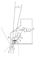
- FIG. 1 is a schematic diagram for explaining a method for adjusting the position of the vehicle display device 100 according to the first embodiment.
- the posture determination device 200 and the calibration pattern 300 are used for the position adjustment of the vehicle display device 100.
- the vehicle display device 100 includes a HUD 110, a viewpoint detection camera 120, and a display control ECU (Electronic Control Unit) 130.
- a display control ECU Electronic Control Unit 130.
- the HUD 110 displays a virtual image on the driver's forward visual field, and is composed of a head-up display. This method can be applied regardless of whether the HUD 110 is a so-called windshield type or combiner type.
- the viewpoint detection camera 120 captures the driver's face.
- the captured video is used for measuring the viewpoint position of the driver.
- the viewpoint detection camera 120 is configured by a monocular camera, a stereo camera, or the like. In the present embodiment, the description will be made assuming that a stereo camera is used.
- the viewpoint detection camera 120 may be installed anywhere as long as the driver's face can be photographed from the direction as close to the front as possible, such as in a dashboard or meter.
- the display control ECU 130 controls each component constituting the vehicular display device 100 such as photographing by the viewpoint detection camera 120 and a display position of the HUD 110.
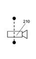
- the posture determination device 200 includes a measurement camera 210 and a PC 220.
- the measurement camera 210 is a camera installed in the vehicle only when the display position of the virtual image displayed by the HUD 110 is adjusted.
- the measurement camera 210 captures a virtual image displayed by the calibration pattern 300 and the HUD 110.
- the measurement camera is configured by a combination of, for example, a stereo camera and a distance sensor.
- the PC 220 determines the attitude of the HUD 110 from the video captured by the measurement camera 210 and the video captured by the viewpoint detection camera 120.
- the calibration pattern 300 is installed in the vehicle only during position adjustment.
- FIG. 2 is a functional block diagram of the vehicle display device 100 and the posture determination device 200.
- the vehicle display device 100 includes a display unit 111 corresponding to the HUD 110 in FIG. 1, an imaging unit 121 corresponding to the viewpoint detection camera 120 in FIG. 1, a viewpoint detection unit 131 corresponding to the display control ECU 130 in FIG. 1, and a display control unit. 132, a CPU 133, a memory 134, and an output I / F 135.
- the posture determination apparatus 200 includes an imaging unit 211 corresponding to the measurement camera 210 in FIG. 1, a CPU 221 that configures the PC 220 in FIG. 1, and an output I / F 222.
- the memory card 400 is used for data exchange between the vehicle display device 100 and the posture determination device 200.
- the display unit 111 displays a virtual image on the driver's field of view.
- the imaging unit 121 captures the driver's face for a predetermined period, for example, 30 images per second.
- the imaging unit 121 is configured in combination with a distance sensor or the like.
- the viewpoint detection unit 131 detects the viewpoint position of the driver from the video captured by the imaging unit 121 for a predetermined period.
- the viewpoint position for example, the three-dimensional position of the viewpoint can be obtained by obtaining the viewpoint parallax from the two images taken by the imaging unit 121.
- the display control unit 132 controls the display position and display contents of the virtual image displayed on the display unit 111. In addition, the display control unit 132 controls the display position of the display unit 111 according to the posture information calculated by the posture determination device 200.
- CPU 133 is a controller for controlling the operation of the entire vehicle display device 100.
- hardware such as a DSP (Digital Signal Processor) or an FPGA (Field-Programmable Gate Array) may be used.
- the memory 134 is used to store the work memory of the CPU 133, the video shot by the imaging unit 121, the detection result of the viewpoint detection unit 131, and the like.
- the memory 134 includes a volatile memory such as a DRAM and a nonvolatile memory such as a flash memory.
- the output I / F (Interface) 135 is used to output the video imaged by the imaging unit 121 to the posture determination device 200 and to input posture information from the posture determination device 200.
- the output I / F 135 is a memory card interface or the like when recording video captured by the imaging unit 121 on a portable memory card 400 or reading posture information from the memory card 400.
- the imaging unit 211 is used to capture a calibration pattern 300 and a virtual image displayed by the HUD 110.
- the CPU 221 is a controller for controlling each component constituting the PC 220, and includes a nonvolatile memory in which a program is stored, a nonvolatile memory that is a temporary storage area for executing the program, an input / output port, and a program Having a processor for executing
- the PC 220 determines the relative position and posture (relative posture) of the HUD 110 and the viewpoint detection camera 120 in FIG. 1 from the image captured by the image capturing unit 211 and the image captured by the image capturing unit 121 of the vehicle display device 100. Posture information for adjusting the display position is calculated.
- the output I / F 222 is used for inputting video captured by the imaging unit 121 of the vehicle display device 100 and outputting posture information calculated by the CPU 221. Specifically, this is a memory card interface or the like in the case where the video taken by the imaging unit 121 is read from the memory card 400 or the posture information calculated by the CPU 221 is recorded in the memory card 400.
- the memory card 400 is a portable recording medium, and is used for input / output of video captured by the imaging unit 121 and attitude information calculated by the attitude determination device 200.
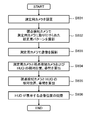
- FIG. 3 is a flowchart showing the flow of processing of the position adjustment method in the present embodiment.
- FIG. 4 is a diagram showing an installation example of a calibration pattern in the present embodiment.
- FIG. 5 is a diagram showing another installation example of the calibration pattern in the present embodiment.
- the measurement camera 210 and the calibration pattern 300 are installed at predetermined positions in the vehicle (step S301).
- the measurement camera 210 is installed at a position where a virtual image displayed by the HUD 110 can be taken.
- the calibration pattern is arranged at a predetermined position with respect to the viewing angle of the virtual image and the angle of view of the viewpoint detection camera 120.
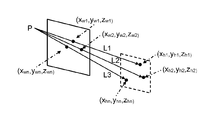
- the calibration pattern 300 is a range in which three angles of the viewing angle ⁇ 1 of the virtual image A displayed by the HUD 110, the viewing angle ⁇ 2 of the viewpoint detection camera, and the viewing angle ⁇ 3 of the measurement camera overlap. It is desirable to install in B (filled area).
- the calibration pattern 300 may be arranged so as to straddle the common range ⁇ 2 of the angle of view ⁇ 2 of 210.
- the common range ⁇ 1 is located outside the angle of view ⁇ 2 of the viewpoint detection camera 120
- the common range ⁇ 2 is located outside the viewing angle ⁇ 1 of the virtual image A.
- the calibration pattern 300 has a plate shape, but is not limited to this.
- the calibration pattern 300 may have any shape as long as it is a known shape that spans the common ranges ⁇ 1 and ⁇ 2. For example, when viewed from the measurement camera 210, a shape in which a portion located in the ⁇ 1 region and a portion located in the ⁇ 2 region have different depths may be used.
- the calibration pattern 300 is photographed by each of the measurement camera 210 and the viewpoint detection camera 120 (step S302).
- the CPU 133 of the vehicle display device 100 causes the viewpoint detection camera 120 to photograph the calibration pattern 300 and causes the memory 134 to record the photographed image.
- the CPU 221 of the posture determination apparatus 200 causes the measurement camera 210 to photograph the calibration pattern 300.
- the calibration pattern 300 is moved outside the viewing angle ⁇ 1 of the virtual image A.
- the CPU 221 of the posture determination apparatus 200 causes the measurement camera 210 to capture the virtual image A (step S303).
- the virtual image A is displayed with a characteristic pattern that can identify in which position of the measurement camera 210 each pixel of the virtual image A is reflected.
- characteristic patterns patterns with different colors for each pixel, patterns with luminance and color changing at different timings for each pixel, and the like can be considered.
- the CPU 221 of the posture determination apparatus 200 calculates the relative posture of the measurement camera 210 and the viewpoint detection camera 120 from the images captured by the measurement camera 210 and the viewpoint detection camera 120, and the measurement camera 210 and the HUD 110.
- the relative posture is calculated (step S304).
- the memory card 400 is connected to the output I / F 135 of the vehicular display device 100, and the video taken by the viewpoint detection camera 120 recorded in the memory 134 is recorded in the memory card 400. Thereafter, the memory card 400 is connected to the output I / F of the attitude determination device 200.
- the CPU 221 of the posture determination apparatus 200 reads the video captured by the viewpoint detection camera 120 from the memory card 400.
- the CPU 221 calculates the relative attitude of the viewpoint detection camera 120 with respect to the measurement camera 210 by using the video imaged by the viewpoint detection camera 120 and the measurement camera 210, and calculates the relative attitude of the HUD 110 with respect to the measurement camera 210. calculate.
- the CPU 221 of the attitude determination device 200 calculates the relative attitude of the HUD 110 with respect to the viewpoint detection camera 120 from the relative attitude of the viewpoint detection camera 120 and HUD 110 with respect to the measurement camera 210 (step S305).
- the CPU 221 records the calculation result as posture information in the memory card 400 via the output I / F 222 of the posture determination apparatus 200.
- the CPU 133 of the vehicle display device 100 reads the posture information calculated by the posture determination device 200 from the memory card 400 via the output I / F 135 of the vehicle display device 100 and records it in the memory 134.
- the CPU 133 causes the display control unit 132 to adjust the display position of the virtual image displayed by the HUD 110 according to the recorded posture information (step S306).
- (x w, y w, z w) represents the P coordinate point on the three-dimensional coordinate system constituted by the measuring camera 210
- (x c, y c , z c) are The coordinates when the point P is viewed in the three-dimensional coordinate system configured by the viewpoint detection camera 120 are represented.
- R c11 to R c33 correspond to the rotation of the coordinate system
- (t cx , t cy , t cz ) corresponds to the parallel movement amount of the origin of the coordinate system.
- the measurement camera 210 and the viewpoint detection camera obtain the values of the nine variables of the rotation R c of the coordinate system and the three variables of the parallel movement amount t c of the coordinate system origin, a total of 12 variables. This corresponds to obtaining a relative posture between 120.
- the results of measuring the coordinates of n points on the calibration pattern 300 with the measurement camera 210 are (x w1 , y w1 , z w1 ), (x w2 , y w2 , z w2 ), (x wn , y wn , z wn ). Also, the results of measuring the coordinates of n points on the calibration pattern 300 with the viewpoint detection camera 120 are (x c1 , y c1 , z c1 ), (x c2 , y c2 , z c2 ) ,. cn , y cn , z cn ). Of the results of substituting these into (Equation 1), focusing on the first row portion of the matrix, (Equation 2) is obtained.
- the three-dimensional position of the HUD 110 pixel is known, it can be handled in the same way as the viewpoint detection camera 120.
- the viewpoint position changes the HUD 110 virtual image is distorted in shape due to the influence of the windshield and combiner shape, There is a possibility that a correct three-dimensional position cannot be measured by stereo matching.
- the range in which the virtual image can be observed is narrow, the virtual image may not be observed with both eyes of the stereo camera. Therefore, the three-dimensional position of the virtual image is determined by the following method.
- the optical center position of the HUD 110 and the orientation of the optical axis that is, the relative orientation with respect to the measurement camera 210, where the virtual image is projected as viewed from the measurement camera 210 is uniquely determined from the design specifications of the HUD 110. . Therefore, it can be understood that it is sufficient to determine whether or not the assumed posture is correct.
- a method for determining whether the assumed posture is correct will be described.
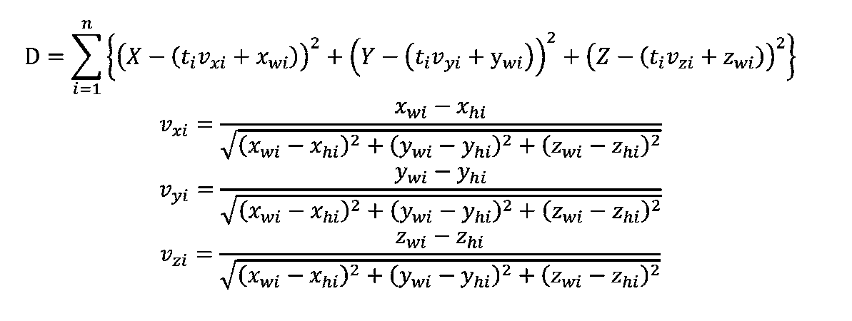
- HUD110 pixel (u h1, v h1), (u h2, v h2), ..., (u hn, v hn) , and when projected with some orientation in space, 3 in the coordinate system of the measuring camera 210
- the dimensional coordinates are (x h1 , y h1 , z h1 ), (x h2 , y h2 , z h2 ),..., (X hn , y hn , z hn ), respectively.
- ti can be obtained by a method such as a least square method, (x h1 , y h1 , z h1 ), (x h2 .
- the correct posture can be obtained by obtaining the posture from which y h2 , z h2 ),..., (x hn , y hn , z hn ) are obtained by a method such as the least square method.
- the relative attitude of the HUD 110 with respect to the viewpoint detection camera 120 is calculated from the relative attitude of the viewpoint detection camera 120 and the HUD 110 with respect to the measurement camera 210 obtained in step S304 of FIG. 3 (step S305). Specifically (number 1), to erase from equation (4) (x w, y w , z w), to obtain the following (Equation 5).
- the matrix part in (Expression 5) represents the relative attitude of the HUD with respect to the viewpoint detection camera. That is, the matrix part of (Equation 5) corresponds to the posture information.
- the CPU 133 of the vehicle display device 100 performs an operation for converting the three-dimensional position of the driver's viewpoint obtained by the viewpoint detection camera 120 into a three-dimensional position in the coordinate system of the HUD 110.
- the display control unit 132 adjusts the display position of the HUD 110 according to the calculation result of the CPU 133.
- the display position adjustment method is a vehicle display device 100 that includes a HUD 110 that displays a virtual image on the driver's forward visual field and a viewpoint detection camera 120 that images the driver.
- the measurement camera 210 is installed at a position where the calibration pattern 300 for acquiring information for capturing can be photographed, and the field angle ⁇ 1 of the virtual image, the field angle ⁇ 2 of the viewpoint detection camera, and the field angle of the measurement camera ⁇ 3 are set.
- the calibration pattern 300 is arranged at a predetermined position. Next, the calibration pattern 300 is photographed by the viewpoint detection camera 120 and the measurement camera 210, and a virtual image is photographed by the measurement camera 210.
- the relative position and orientation of the measurement camera 210 and the viewpoint detection camera 120 are calculated, and the measurement camera 210 and the HUD 110 are calculated. Then, the relative position and orientation of the viewpoint detection camera 120 and the HUD 110 are calculated as orientation information. The position of the virtual image displayed by the HUD 110 is adjusted using the calculated posture information.
- the relative posture between the HUD 110 and the viewpoint detection camera 120 can be easily measured.
- the display position of the HUD 110 can be easily adjusted.
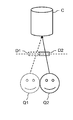
- both the viewpoint detection camera and the HUD have an error factor such as a variation at the time of assembly or a shift at the time of mounting the vehicle body, and the positional relationship between the two is likely to be different from the assumption at the time of design. Accordingly, as shown in FIG. 7A, a deviation occurs between the measured viewpoint position Q1 and the viewpoint position Q2 at the time of design. In this case, even if the virtual image I is displayed so as to overlap the object C when viewed from the viewpoint position Q1, the virtual image I cannot be seen from the true viewpoint position Q2 because it overlaps the object C.
- the true viewpoint position Q2 can be calculated from the measured viewpoint position Q1, so that a virtual image is formed at a position overlapping the object C as viewed from the viewpoint position Q2, as shown in FIG. 7B. D2 can be displayed.
- the calibration pattern is separate from both the viewpoint detection camera and the measurement camera. However, even when the calibration pattern is attached to the measurement camera, calibration is performed according to the following procedure. It can be performed.
- FIG. 8 is a flowchart showing a processing flow of the position adjustment method in the present embodiment.
- FIG. 9 is a diagram showing an installation example of a calibration pattern in the present embodiment.
- step S802 the calibration pattern is attached to the measurement camera, and therefore the calibration pattern is photographed only by the viewpoint detection camera 120.
- the calibration pattern needs to have a shape that fits within the angle of view of the viewpoint detection camera 120 as shown in FIG.
- the calibration pattern is attached to the lower part of the measurement camera 210, but the specific position is not necessarily as shown in this figure.
- the upper part of the measurement camera 210 or a plurality of locations It may be attached to.
- the “three-dimensional coordinate system configured by the viewpoint detection camera 120” is converted into the “three-dimensional coordinate system configured by the measurement camera 210”.
- the position of the origin of the coordinate system to be converted it is necessary to determine the position of the origin of the coordinate system to be converted and the orientation of the coordinate system.
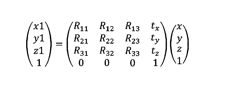
- the following (Equation 6) holds between the position (x, y, z) in the coordinate system before conversion and the position (x1, y1, z1) in the coordinate system after conversion.
- R 11 to R 33 are matrices representing the rotation of the coordinate system, and can be easily obtained if the orientation of the coordinate system after conversion is known.
- (T x , t y , t z ) corresponds to the translation amount of the origin of the coordinate system.
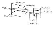
- three points are formed in a regular triangle shape as a calibration pattern 300 for measurement.
- the calibration pattern 300 is arranged so that the optical center of the camera 210 (the origin of the three-dimensional coordinate system constituted by the measurement camera 210) is located at the center of gravity of the equilateral triangle, and the viewpoint detection camera 120 defines the calibration pattern 300.
- Three-dimensional coordinates of three points are measured.
- the center of gravity of the three-dimensional coordinates thus measured represents the position of the optical center of the measurement camera 210, and the normal direction of the surface determined from the three-dimensional coordinates of the three points represents the direction of the measurement camera 210.
- examples of the calibration pattern are not limited to those shown in FIGS. 10A and 10B, and the position of the measurement camera 210 is known with respect to the optical center, and the orientation of the measurement camera 210 can be defined. Any pattern that can define three or more coordinates that are not on a straight line can be used.
- a virtual image is projected wherever viewed from the measurement camera 210. This is uniquely determined from the design specifications of the HUD 110. Positions (u 1 , u) on the image of the measurement camera 210 when n pixels of the virtual image (where n ⁇ 3 and at least one is not on the same straight line) take a posture with the HUD 110. v 1 ), (u 2 , v 2 ),..., (u n , v n ) are calculated.
- the minimization of D1 can be performed using a numerical algorithm such as Newton's method or a stochastic algorithm such as simulated annealing.
- a translucent object may be used as the calibration pattern. Accordingly, it is not necessary to install or move the calibration pattern when taking a virtual image of the HUD, and the working time can be shortened.
- each block may be individually made into one chip by a semiconductor device such as an LSI, or may be made into one chip so as to include a part or all of the blocks. .
- LSI LSI
- IC system LSI
- super LSI ultra LSI depending on the degree of integration
- the method of circuit integration is not limited to LSI, and may be realized by a dedicated circuit or a general-purpose processor.
- An FPGA Field Programmable Gate Array
- a reconfigurable processor that can reconfigure the connection and setting of circuit cells inside the LSI may be used.
- each process of the above embodiment may be realized by hardware or software. Further, it may be realized by mixed processing of software and hardware. Needless to say, when the digital camera according to the above-described embodiment is realized by hardware, it is necessary to adjust timing for performing each process. In the above embodiment, for convenience of explanation, details of timing adjustment of various signals generated in actual hardware design are omitted.
- vehicle display device 110 HUD 111 Display Unit 120 Viewpoint Detection Camera 121, 211 Imaging Unit 130 Display Control ECU 131 Viewpoint detection unit 132 Display control unit 133, 221 CPU 134 Memory 135, 222 Output I / F 200 posture determination device 210 measurement camera 220 PC 300 Calibration pattern 400 Memory card
Landscapes
- Engineering & Computer Science (AREA)
- Physics & Mathematics (AREA)
- General Physics & Mathematics (AREA)
- Theoretical Computer Science (AREA)
- Optics & Photonics (AREA)
- Mechanical Engineering (AREA)
- Multimedia (AREA)
- Transportation (AREA)
- Combustion & Propulsion (AREA)
- Chemical & Material Sciences (AREA)
- Computer Vision & Pattern Recognition (AREA)
- Instrument Panels (AREA)
- Fittings On The Vehicle Exterior For Carrying Loads, And Devices For Holding Or Mounting Articles (AREA)
- Length Measuring Devices By Optical Means (AREA)
- Closed-Circuit Television Systems (AREA)
Abstract
Description
以下、図1~図7A、図7Bを用いて、第1の実施の形態を説明する。
[1-1-1.装置構成]
図1は、第1の実施の形態における車両用表示装置100の位置調整方法を説明するための模式図である。
図2は、車両用表示装置100および姿勢判定装置200の機能ブロック図である。
図3は本実施の形態における位置調整方法の処理の流れを示すフローチャートである。図4は、本実施の形態における較正用パターンの設置例を示す図である。図5は、本実施の形態における較正用パターンの他の設置例を示す図である。
まず、測定用カメラ210と較正用パターン300を車両内の所定の位置に設置する(ステップS301)。測定用カメラ210はHUD110が表示する虚像を撮影可能な位置に設置する。較正用パターンは、虚像の視野角と視点検知カメラ120の画角に対して、所定の位置に配置する。
ここでは、姿勢判定装置200が算出する姿勢情報の算出方法について詳細に説明する。

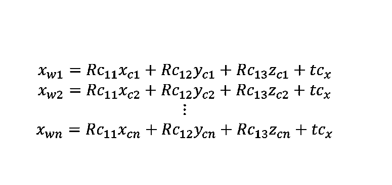
まず、較正用パターン300のn個の点について、測定用カメラ210の座標系における3次元位置(xw1,yw1,zw1)、(xw2,yw2,zw2)、…、(xwn,ywn,zwn)と、画像上の座標(uw1,vw1)、(uw2,vw2)、…、(uwn,vwn)を求める。次いでHUD110が表示した虚像を撮影した画像から、(uw1,vw1)、(uw2,vw2)、…、(uwn,vwn)の位置にHUD110の虚像のどの画素が写っているかを判定する。以下、判定されたHUD110の画素の座標を(uh1,vh1)、(uh2,vh2)、…、(uhn,vhn)とする。


本実施の形態の表示位置調整方法は、運転者の前方視野上に虚像を表示するHUD110と、運転者を撮影する視点検知カメラ120とを備えた車両用表示装置100において、虚像および位置調整のための情報を取得するための較正用パターン300を撮影可能な位置に測定用カメラ210を設置すると共に、虚像の視野角θ1、視点検知カメラの画角θ2、および測定用カメラθ3の画角に対して所定の位置に較正用パターン300を配置する。次に、視点検知カメラ120および測定用カメラ210で較正用パターン300を撮影し、測定用カメラ210で虚像を撮影する。次に視点検知カメラ120によって撮影された映像と測定用カメラ210によって撮影された映像とを用いて、測定用カメラ210と視点検知カメラ120の相対位置と姿勢の算出、および測定用カメラ210とHUD110の相対位置と姿勢の算出を行った後、視点検知カメラ120とHUD110の相対位置と姿勢を姿勢情報として算出する。算出した姿勢情報を用いてHUD110が表示する虚像の位置を調整する。
第1の実施の形態において、較正用パターンは視点検知カメラ、測定用カメラのいずれとも別体であったが、較正用パターンが測定用カメラに取り付けられている場合でも、以下に示す手順で較正を行うことができる。なお、第2の実施の形態における装置の構成は第1の実施の形態と重複するため記載を省略するものとする。その他第1の実施の形態と同様の箇所についても記載を省略する。
図8は本実施の形態における位置調整方法の処理の流れを示すフローチャートである。図9は本実施の形態における較正用パターンの設置例を示す図である。
処理の流れは図3で示した第1の実施の形態における処理の流れとほぼ同一である。大きく異なるのはステップS802で、較正用パターンが測定用カメラに取り付けられているため、視点検知カメラ120のみで較正用パターンを撮影する。較正用パターンは図9に示すように視点検知カメラ120の画角に収まるような形状である必要がある。なお、図9において較正用パターンは測定用カメラ210の下部に取り付けられているが、具体的な位置は必ずしもこの図の通りでなくてもよく、例えば測定用カメラ210の上部や、複数の箇所に取り付けられていてもよい。
第1の実施の形態と同様に、まずは「視点検知カメラ120によって構成される3次元座標系」を「測定用カメラ210によって構成される3次元座標系」に変換する。一般に座標系間の変換を行うには、変換したい座標系の原点の位置および座標系の向きを定める必要がある。具体的には変換前の座標系での位置(x,y,z)と変換後の座標系での位置(x1,y1,z1)との間には以下の(数6)が成り立つ。
較正用パターン300が測定用カメラ210の画角内かつHUD110の虚像の視野角内に存在する場合は実施の形態1で用いた方法をそのまま用いることが出来る。この条件を満たさない場合は以下のようにして測定用カメラとHUDの間の相対姿勢を測定する。

以上のようにして測定用カメラと視点検知カメラの間の相対姿勢、および測定用カメラとHUDの間の相対姿勢を定めることができれば、実施の形態1と同様の考え方で両者を結びつけ、視点検知カメラとHUDの間の相対姿勢を計測することが出来る。
以上のように、本出願において開示する技術の例示として、実施の形態を説明した。しかしながら、本開示における技術は、これに限定されず、適宜、変更、置き換え、付加、省略などを行った実施の形態にも適用可能である。また、上記実施の形態で説明した各構成要素を組み合わせて、新たな実施の形態とすることも可能である。
110 HUD
111 表示部
120 視点検知カメラ
121,211 撮像部
130 表示制御ECU
131 視点検出部
132 表示制御部
133,221 CPU
134 メモリ
135,222 出力I/F
200 姿勢判定装置
210 測定用カメラ
220 PC
300 較正用パターン
400 メモリカード
Claims (7)
- 運転者の前方視野上に虚像を表示する表示装置と、
前記運転者を撮影する視点検知カメラと、
を備えた車両表示装置の位置調整方法であって、
前記虚像および位置調整のための情報を取得するための較正用パターンを撮影可能な位置に測定用カメラを設置すると共に、
前記虚像の視野角、前記視点検知カメラの画角、および前記測定用カメラの画角に対して所定の位置に前記較正用パターンを配置するステップと、
前記視点検知カメラおよび前記測定用カメラで前記較正用パターンを撮影するステップと、
前記測定用カメラで前記虚像を撮影するステップと、
前記視点検知カメラによって撮影された映像と前記測定用カメラによって撮影された映像とを用いて、前記測定用カメラと前記視点検知カメラの相対位置と姿勢を算出するとともに、前記測定用カメラと前記表示装置の相対位置と姿勢を算出し、2つの前記相対位置と姿勢から前記視点検知カメラと前記表示装置の相対位置と姿勢を姿勢情報として算出するステップと、
前記姿勢情報を用いて前記表示装置が表示する前記虚像の位置を調整するステップとからなる車両用表示装置の位置調整方法。 - 前記虚像の視野角と、前記視点検知カメラの画角と、前記測定用カメラの画角が重なる範囲内に前記較正用パターンを設置する請求項1に記載の車両用表示装置の位置調整方法。
- 前記虚像の視野角と前記測定用カメラの画角が重なる範囲であり、かつ前記視点検知カメラの画角外である領域と、前記視点検知カメラの画角と前記測定用カメラの画角が重なる範囲であり、かつ前記虚像の視野角の範囲外である領域に跨って、前記較正用パターンを設置する請求項1に記載の車両用表示装置の位置調整方法。
- 前記較正用パターンは半透明である請求項2または3のいずれか一項に記載の車両用表示装置の位置調整方法。
- 前記表示装置と前記視点検知カメラの位置関係を判定するステップにおいて、前記表示装置によって表示される虚像が、前記測定用カメラで撮影された画像のどの画素に前記虚像のどの画素が写っているかを特定するための特徴的なパターンを備えていることを特徴とする、請求項1から4のいずれか一項に記載の車両用表示装置の位置調整方法。
- 前記画素を特定するための特徴的なパターンが、時間的に色や輝度が変化するパターンであることを特徴とする、請求項5に記載の車両用表示装置の位置調整方法。
- 運転者の前方視野上に虚像を表示する表示装置と、
前記運転者を撮影する視点検知カメラと、
を備えた車両表示装置の位置調整方法であって、
前記虚像を撮影する測定用カメラを設置すると共に、
前記測定用カメラに対して所定の位置に取り付けられた位置調整のための情報を取得するための較正用パターンを前記視点検知カメラで撮影するステップと、
前記測定用カメラで前記虚像を撮影するステップと、
前記視点検知カメラによって撮影された映像と前記測定用カメラによって撮影された映像とを用いて、前記測定用カメラと前記視点検知カメラの相対位置と姿勢の算出、および前記測定用カメラと前記表示装置の相対位置と姿勢の算出を行い、2つの前記相対位置と姿勢から前記視点検知カメラと前記表示装置の相対位置と姿勢を姿勢情報として算出するステップと、
前記姿勢情報を用いて前記表示装置が表示する前記虚像の位置を調整するステップとからなる車両用表示装置の位置調整方法。
Priority Applications (3)
| Application Number | Priority Date | Filing Date | Title |
|---|---|---|---|
| JP2016557667A JP6518952B2 (ja) | 2015-03-27 | 2016-03-18 | 車両用表示装置の位置調整方法 |
| EP16771692.7A EP3147150B1 (en) | 2015-03-27 | 2016-03-18 | Method for adjusting position of vehicular display apparatus |
| US15/263,993 US9772496B2 (en) | 2015-03-27 | 2016-09-13 | Position adjustment method of vehicle display device |
Applications Claiming Priority (2)
| Application Number | Priority Date | Filing Date | Title |
|---|---|---|---|
| JP2015065879 | 2015-03-27 | ||
| JP2015-065879 | 2015-03-27 |
Related Child Applications (1)
| Application Number | Title | Priority Date | Filing Date |
|---|---|---|---|
| US15/263,993 Continuation US9772496B2 (en) | 2015-03-27 | 2016-09-13 | Position adjustment method of vehicle display device |
Publications (1)
| Publication Number | Publication Date |
|---|---|
| WO2016157799A1 true WO2016157799A1 (ja) | 2016-10-06 |
Family
ID=57005863
Family Applications (1)
| Application Number | Title | Priority Date | Filing Date |
|---|---|---|---|
| PCT/JP2016/001577 Ceased WO2016157799A1 (ja) | 2015-03-27 | 2016-03-18 | 車両用表示装置の位置調整方法 |
Country Status (4)
| Country | Link |
|---|---|
| US (1) | US9772496B2 (ja) |
| EP (1) | EP3147150B1 (ja) |
| JP (1) | JP6518952B2 (ja) |
| WO (1) | WO2016157799A1 (ja) |
Cited By (2)
| Publication number | Priority date | Publication date | Assignee | Title |
|---|---|---|---|---|
| WO2019111520A1 (ja) * | 2017-12-06 | 2019-06-13 | 株式会社Jvcケンウッド | 投影制御装置、ヘッドアップディスプレイ装置、投影制御方法およびプログラム |
| JP2019099142A (ja) * | 2017-12-06 | 2019-06-24 | 三星電子株式会社Samsung Electronics Co.,Ltd. | 仮想スクリーンのパラメータ推定方法及び装置 |
Families Citing this family (17)
| Publication number | Priority date | Publication date | Assignee | Title |
|---|---|---|---|---|
| EP2972478B1 (en) | 2013-03-15 | 2020-12-16 | Uatc, Llc | Methods, systems, and apparatus for multi-sensory stereo vision for robotics |
| JP6636252B2 (ja) * | 2015-03-19 | 2020-01-29 | 株式会社メガチップス | 投影システム、プロジェクター装置、撮像装置、および、プログラム |
| US10116873B1 (en) * | 2015-11-09 | 2018-10-30 | Ambarella, Inc. | System and method to adjust the field of view displayed on an electronic mirror using real-time, physical cues from the driver in a vehicle |
| US10077007B2 (en) * | 2016-03-14 | 2018-09-18 | Uber Technologies, Inc. | Sidepod stereo camera system for an autonomous vehicle |
| DE102017214934B3 (de) | 2017-08-25 | 2019-02-07 | Panasonic Automotive & Industrial Systems Europe GmbH | Videobildaufnahmeverfahren, Wiedergabeverfahren, Ausrüstung für ein Fahrzeug, eingerichtet zum Ausführen eines Videobildaufnahmeverfahrens und Testsystem zum Ausführen eines Wiedergabeverfahrens |
| US10967862B2 (en) | 2017-11-07 | 2021-04-06 | Uatc, Llc | Road anomaly detection for autonomous vehicle |
| CN116620019A (zh) * | 2017-11-14 | 2023-08-22 | 麦克赛尔株式会社 | 平视显示装置和车辆 |
| KR102518661B1 (ko) | 2018-10-16 | 2023-04-06 | 현대자동차주식회사 | Hud 시스템의 이미지 왜곡 보정 방법 |
| KR102707598B1 (ko) * | 2018-12-04 | 2024-09-19 | 삼성전자주식회사 | 3차원 증강 현실을 위한 캘리브레이션 방법 및 그 장치 |
| CN109801341B (zh) * | 2019-01-30 | 2020-11-03 | 北京经纬恒润科技有限公司 | 一种标定靶的位置校验方法及装置 |
| CN109889807A (zh) * | 2019-03-14 | 2019-06-14 | 百度在线网络技术(北京)有限公司 | 车载投射调节方法、装置、设备和存储介质 |
| CN111664839B (zh) * | 2020-05-20 | 2022-03-08 | 重庆大学 | 车载抬头显示虚像距离测量方法 |
| US11833901B2 (en) | 2020-10-12 | 2023-12-05 | GM Global Technology Operations LLC | System and method for adjusting a location and distortion of an image projected onto a windshield of a vehicle by a head-up display |
| EP4269153B1 (en) | 2021-03-02 | 2025-12-17 | Samsung Electronics Co., Ltd. | Electronic device for projecting image on windshield of vehicle, and operating method therefor |
| CN114494439B (zh) * | 2022-01-25 | 2023-08-15 | 襄阳达安汽车检测中心有限公司 | Hil仿真测试中摄像头位姿校准方法、装置、设备及介质 |
| CN115330699B (zh) * | 2022-07-27 | 2026-01-23 | 东软集团股份有限公司 | 用于抬头显示器hud的调节方法、装置及存储介质 |
| US20250316194A1 (en) * | 2024-04-09 | 2025-10-09 | DISTANCE TECHNOLOGIES Oy | Light field display based on relative location of viewer |
Citations (3)
| Publication number | Priority date | Publication date | Assignee | Title |
|---|---|---|---|---|
| JP2002205571A (ja) * | 2001-01-10 | 2002-07-23 | Yazaki Corp | 車両用表示装置 |
| JP2009262666A (ja) * | 2008-04-23 | 2009-11-12 | Calsonic Kansei Corp | 車両用ヘッドアップディスプレイ装置の調整方法 |
| JP2013218346A (ja) * | 2013-05-30 | 2013-10-24 | Denso Corp | ヘッドアップディスプレイ装置の製造方法および同製造方法に用いるのに適した虚像調整装置 |
Family Cites Families (3)
| Publication number | Priority date | Publication date | Assignee | Title |
|---|---|---|---|---|
| US7663502B2 (en) * | 1992-05-05 | 2010-02-16 | Intelligent Technologies International, Inc. | Asset system control arrangement and method |
| US8358224B2 (en) * | 2009-04-02 | 2013-01-22 | GM Global Technology Operations LLC | Point of interest location marking on full windshield head-up display |
| KR101544524B1 (ko) * | 2010-12-16 | 2015-08-17 | 한국전자통신연구원 | 차량용 증강현실 디스플레이 시스템 및 차량용 증강현실 디스플레이 방법 |
-
2016
- 2016-03-18 WO PCT/JP2016/001577 patent/WO2016157799A1/ja not_active Ceased
- 2016-03-18 JP JP2016557667A patent/JP6518952B2/ja not_active Expired - Fee Related
- 2016-03-18 EP EP16771692.7A patent/EP3147150B1/en active Active
- 2016-09-13 US US15/263,993 patent/US9772496B2/en active Active
Patent Citations (3)
| Publication number | Priority date | Publication date | Assignee | Title |
|---|---|---|---|---|
| JP2002205571A (ja) * | 2001-01-10 | 2002-07-23 | Yazaki Corp | 車両用表示装置 |
| JP2009262666A (ja) * | 2008-04-23 | 2009-11-12 | Calsonic Kansei Corp | 車両用ヘッドアップディスプレイ装置の調整方法 |
| JP2013218346A (ja) * | 2013-05-30 | 2013-10-24 | Denso Corp | ヘッドアップディスプレイ装置の製造方法および同製造方法に用いるのに適した虚像調整装置 |
Non-Patent Citations (1)
| Title |
|---|
| See also references of EP3147150A4 * |
Cited By (3)
| Publication number | Priority date | Publication date | Assignee | Title |
|---|---|---|---|---|
| WO2019111520A1 (ja) * | 2017-12-06 | 2019-06-13 | 株式会社Jvcケンウッド | 投影制御装置、ヘッドアップディスプレイ装置、投影制御方法およびプログラム |
| JP2019101323A (ja) * | 2017-12-06 | 2019-06-24 | 株式会社Jvcケンウッド | 投影制御装置、ヘッドアップディスプレイ装置、投影制御方法およびプログラム |
| JP2019099142A (ja) * | 2017-12-06 | 2019-06-24 | 三星電子株式会社Samsung Electronics Co.,Ltd. | 仮想スクリーンのパラメータ推定方法及び装置 |
Also Published As
| Publication number | Publication date |
|---|---|
| EP3147150A4 (en) | 2017-10-25 |
| JP6518952B2 (ja) | 2019-05-29 |
| EP3147150A1 (en) | 2017-03-29 |
| EP3147150B1 (en) | 2018-09-26 |
| US20160377873A1 (en) | 2016-12-29 |
| JPWO2016157799A1 (ja) | 2018-01-18 |
| US9772496B2 (en) | 2017-09-26 |
Similar Documents
| Publication | Publication Date | Title |
|---|---|---|
| JP6518952B2 (ja) | 車両用表示装置の位置調整方法 | |
| CN112655024B (zh) | 一种图像标定方法及装置 | |
| JP6458439B2 (ja) | 車載カメラ較正装置、画像生成装置、車載カメラ較正方法、画像生成方法 | |
| JP7018566B2 (ja) | 撮像装置、画像処理方法及びプログラム | |
| CN108141570B (zh) | 校准装置、校准方法以及校准程序存储介质 | |
| JP4861034B2 (ja) | 車載カメラのキャリブレーションシステム | |
| US8872920B2 (en) | Camera calibration apparatus | |
| US9866818B2 (en) | Image processing apparatus and method, image processing system and program | |
| JP5615441B2 (ja) | 画像処理装置及び画像処理方法 | |
| JP7038345B2 (ja) | カメラパラメタセット算出方法、カメラパラメタセット算出プログラム及びカメラパラメタセット算出装置 | |
| JP5456330B2 (ja) | 画像表示装置及びそのカメラ取り付け角度算出方法 | |
| EP1884740A2 (en) | Method and system for sensing the surface shape of a reflective object | |
| CN104052986B (zh) | 检测用具、立体照相机检测装置以及检测方法 | |
| JP6791341B2 (ja) | 校正方法、校正装置、及びプログラム | |
| JP6599685B2 (ja) | 画像処理装置および誤差判定方法 | |
| JP2010002233A (ja) | 複眼画像入力装置及びそれを用いた距離測定装置 | |
| JP2009276233A (ja) | パラメータ計算装置、パラメータ計算システムおよびプログラム | |
| CN114450552A (zh) | 校正参数计算方法、位移量计算方法、校正参数计算装置及位移量计算装置 | |
| JP5487946B2 (ja) | カメラ画像の補正方法およびカメラ装置および座標変換パラメータ決定装置 | |
| CN119334655A (zh) | 一种车辆视野测量方法、装置、电子设备及存储介质 | |
| US10726528B2 (en) | Image processing apparatus and image processing method for image picked up by two cameras | |
| JP2010087743A (ja) | 車載カメラの校正装置 | |
| JP2013239905A (ja) | 車載カメラのキャリブレーション装置 | |
| JP2019002787A (ja) | ステレオカメラ装置 | |
| JP7492599B2 (ja) | 車載カメラ装置 |
Legal Events
| Date | Code | Title | Description |
|---|---|---|---|
| ENP | Entry into the national phase |
Ref document number: 2016557667 Country of ref document: JP Kind code of ref document: A |
|
| 121 | Ep: the epo has been informed by wipo that ep was designated in this application |
Ref document number: 16771692 Country of ref document: EP Kind code of ref document: A1 |
|
| REEP | Request for entry into the european phase |
Ref document number: 2016771692 Country of ref document: EP |
|
| WWE | Wipo information: entry into national phase |
Ref document number: 2016771692 Country of ref document: EP |
|
| NENP | Non-entry into the national phase |
Ref country code: DE |