WO2016158166A1 - 投影システム、プロジェクター装置、および、プログラム - Google Patents
投影システム、プロジェクター装置、および、プログラム Download PDFInfo
- Publication number
- WO2016158166A1 WO2016158166A1 PCT/JP2016/056253 JP2016056253W WO2016158166A1 WO 2016158166 A1 WO2016158166 A1 WO 2016158166A1 JP 2016056253 W JP2016056253 W JP 2016056253W WO 2016158166 A1 WO2016158166 A1 WO 2016158166A1
- Authority
- WO
- WIPO (PCT)
- Prior art keywords
- image
- projection
- point
- plane
- unit
- Prior art date
- Legal status (The legal status is an assumption and is not a legal conclusion. Google has not performed a legal analysis and makes no representation as to the accuracy of the status listed.)
- Ceased
Links
Images


Classifications
-
- G—PHYSICS
- G06—COMPUTING OR CALCULATING; COUNTING
- G06T—IMAGE DATA PROCESSING OR GENERATION, IN GENERAL
- G06T5/00—Image enhancement or restoration
- G06T5/80—Geometric correction
-
- H—ELECTRICITY
- H04—ELECTRIC COMMUNICATION TECHNIQUE
- H04N—PICTORIAL COMMUNICATION, e.g. TELEVISION
- H04N9/00—Details of colour television systems
- H04N9/12—Picture reproducers
- H04N9/31—Projection devices for colour picture display, e.g. using electronic spatial light modulators [ESLM]
- H04N9/3179—Video signal processing therefor
- H04N9/3185—Geometric adjustment, e.g. keystone or convergence
-
- G—PHYSICS
- G06—COMPUTING OR CALCULATING; COUNTING
- G06T—IMAGE DATA PROCESSING OR GENERATION, IN GENERAL
- G06T3/00—Geometric image transformations in the plane of the image
- G06T3/60—Rotation of whole images or parts thereof
-
- H—ELECTRICITY
- H04—ELECTRIC COMMUNICATION TECHNIQUE
- H04N—PICTORIAL COMMUNICATION, e.g. TELEVISION
- H04N9/00—Details of colour television systems
- H04N9/12—Picture reproducers
- H04N9/31—Projection devices for colour picture display, e.g. using electronic spatial light modulators [ESLM]
- H04N9/3191—Testing thereof
- H04N9/3194—Testing thereof including sensor feedback
Definitions
- the present invention relates to a technique for appropriately displaying an image (video) projected by a projection type projector apparatus.
- Patent Document 1 Japanese Patent Laid-Open No. 2006-33357 discloses a video projection apparatus that can correct image distortion due to distortion of the screen itself.
- a test image is projected from a projector onto a screen, the projected test image is captured by a camera-equipped mobile phone, and geometric correction is executed based on the image captured by the camera-equipped mobile phone.
- image distortion geometric distortion due to distortion of the screen itself can be corrected.
- a projection type projector device is often a flat screen installed vertically. For this reason, even if projection without a geometric distortion is not realized, the projection type projector apparatus is adjusted to a projection state in which the geometric distortion of the projected image does not matter to the user. It is possible enough. This is because the user can correctly recognize that it is projected on a flat screen that is installed vertically, and it is easy to correctly recognize the vertical direction, so the image that is projected on the flat screen that is the vertical plane This is because there is no sense of incongruity even if some geometric distortion exists.
- the projection target is, for example, a ceiling (hereinafter referred to as “horizontal ceiling”) installed in parallel with the floor
- horizontal ceiling a ceiling
- an image is projected onto the horizontal ceiling from the projection type projector device.
- the surface is a vertical plane
- the present invention projects onto a horizontal projection plane (for example, a horizontal ceiling) or a plane parallel to a straight line connecting both eyes of the user (for example, a front inclined plane or a rear inclined plane) without using a device having a photographing function.
- An object of the present invention is to realize a projection system, a projector apparatus, and a program that can easily and appropriately reduce the geometric distortion of a captured image.
- the projection target is, for example, an inclined plane (for example, an inclined ceiling) inclined above a predetermined angle installed above the user, and an image is projected from the projection type projector device on the inclined plane
- the projection plane is a vertical plane
- the present invention provides a projection system, a projector apparatus, and a projection system that can easily and appropriately reduce geometric distortion of an image projected on an inclined plane (for example, an inclined ceiling) without using an apparatus having a photographing function.
- the purpose is to realize the program.
- the first invention uses a plane parallel to a straight line connecting the left eye viewpoint and the right eye viewpoint as a projection plane, and reduces geometric image distortion when viewed from the user's viewpoint.
- a projection system that projects an image so as to achieve the above state, and includes a projection unit, a three-dimensional shape measurement unit, a controller, and a projection image adjustment unit.
- the projection unit is a projection unit that projects an image on a projection surface, and projects a test image.
- the 3D shape measurement unit measures the 3D shape of the projection surface.
- the controller generates a control signal based on a user operation.
- the projection image adjustment unit passes through the projection center point that is the intersection of the projection axis of the projection unit and the projection plane based on the three-dimensional shape data measured by the three-dimensional shape measurement unit, and is on the normal line of the projection plane.
- the correction point which is an image conversion process, is executed on the test image so that the geometric image distortion is reduced.
- the projection image adjustment unit determines the rotation angle according to the control signal, and when the projection surface is viewed from the first point, the projection image of the test image after the correction processing on the projection surface by the projection unit is the projection center point
- a rotation process which is an image conversion process, is performed on the test image after the correction process so that the image is rotated by the rotation angle determined according to the control signal, centering on.
- a test image showing the upper part when displayed is projected onto a projection plane (for example, a horizontal projection plane such as a horizontal ceiling plane) parallel to a straight line connecting the left eye viewpoint and the right eye viewpoint.
- a projection plane for example, a horizontal projection plane such as a horizontal ceiling plane
- the geometric distortion of the image projected on the projection plane is eliminated by executing the process of rotating the projection image within the projection plane while the user confirms the change state of the test image with the controller ( Can be reduced).
- a plane parallel to the straight line connecting the left eye viewpoint and the right eye viewpoint is projected onto the projection plane (for example, a horizontal projection plane such as a horizontal ceiling plane) without using a device having a photographing function. Therefore, the geometric distortion of the image can be eliminated (reduced) easily and appropriately.
- the projection plane is a plane parallel to a straight line connecting the left eye viewpoint and the right eye viewpoint
- the projection plane is, for example, a projection plane, a front tilt plane, or a rear tilt plane that is a plane parallel to the floor.
- the “straight line connecting the left eye viewpoint and the right eye viewpoint” is, for example, a straight line parallel to the floor when the user stands upright with respect to the floor.
- Front inclined plane means that the floor and the horizontal plane are rotated about the axis that becomes a straight line parallel to the floor (or a straight line parallel to the straight line passing through the left eye viewpoint and right eye viewpoint of the user). It is a plane that is not inclined to the left or right as viewed from the user and is inclined in the forward direction (the direction that is forward when viewed from the user).
- Backward inclined plane means that the floor and the horizontal plane are rotated about the axis that is a straight line parallel to the floor (or a straight line parallel to the straight line passing through the left and right eye viewpoints of the user). It is a plane that is not inclined to the left or right as viewed from the user and is inclined backward (in the direction viewed from the user).
- the measurement of the “three-dimensional shape of the projection plane” includes, for example, (1) measurement for obtaining a normal line of the projection plane and clarifying the positional relationship between the projection section and (2) projection of the projection section. This is a concept including a measurement for obtaining an angle between an axis (optical axis of the optical system of the projection unit) and the projection surface and clarifying a positional relationship between the projection unit and the projection surface.
- the state in which geometric image distortion is reduced means that, for example, the geometric image distortion of the projection image caused by the positional relationship between the projection unit and the projection plane (the angle between the projection axis and the projection plane) is reduced.
- test image after the correction process so that the projection image of the test image after the correction process on the projection plane is an image rotated around the projection center point by the rotation angle determined according to the control signal
- image conversion process to be executed may be realized by the following process, for example.
- the three-dimensional space is defined as xyz coordinates
- the projection plane is set on the xy plane, and after correction processing If the coordinates of the pixel Px of the test image of (x1, y1, z1) and (x1 ′, y1 ′, z1 ′) after the image conversion processing of the pixel Px are (x1 ′, y1 ′, z1 ′), the processing corresponding to the following (Formula 1) By performing the above, the “image conversion process” may be executed.
- test image after correction processing is rotated around the z axis by an angle ⁇ .
- a rotated image can be acquired.
- 2nd invention is 1st invention, Comprising:
- the test image is an image containing the vertical reference line extended in the vertical direction on an image in the state currently displayed on the display screen.
- the projection image adjustment unit determines a distortion reduction amount according to the control signal, and is a plane including a vertical reference line of the projection image projected on the projection plane, and determines the projection plane from a point included in the plane perpendicular to the projection plane.
- a first distance that is the length of the projected image in a direction orthogonal to the vertical reference line passing through the first orthogonal point that is one point on the vertical reference line by an amount corresponding to the distortion reduction amount;
- the difference from the second distance which is the length of the projected image in the direction orthogonal to the vertical reference line, passes through the second orthogonal point other than the first orthogonal point on the vertical reference line (the vertical reference line).
- the image conversion process is applied to the test image after the rotation process. Performing the keystone correction process.
- a test image showing the upper part when displayed is projected onto a projection plane (for example, a horizontal projection plane such as a horizontal ceiling plane) parallel to a straight line connecting the left eye viewpoint and the right eye viewpoint.
- the user uses the controller to (1) execute the process of rotating the projection image within the projection plane, and (2) execute the trapezoidal correction process for the image projected on the projection plane, thereby projecting onto the projection plane. It is possible to eliminate (reduce) the geometric distortion of the image.
- a plane parallel to the straight line connecting the left eye viewpoint and the right eye viewpoint is projected onto the projection plane (for example, a horizontal projection plane such as a horizontal ceiling plane) without using a device having a photographing function. Therefore, the geometric distortion of the image can be eliminated (reduced) easily and appropriately.
- the geometric distortion occurring in the direction orthogonal to the vertical reference line is reduced means, for example, above the projected image (upward in the vertical direction when the image is displayed)
- the length of the projection image in the direction orthogonal to the line (width of the projection image) and the length of the projection image in the direction orthogonal to the vertical reference line below the projection image (down in the vertical direction when the image is displayed) This includes the concept that the difference from the height (the width of the projected image) is small.
- 3rd invention is 2nd invention, Comprising:
- the projection image adjustment part shows the projection state of the image when projecting the test image in which at least one of the rotation process and the trapezoid correction process was performed on the projection plane.
- a fine adjustment unit for adjustment is provided.
- the fine adjustment unit performs the adjustment process. For example, an error in the three-dimensional shape measurement process is corrected, and a more accurate image projection process (a process for reducing image geometric distortion) is performed. Can be executed.
- test image is an image containing the pattern which can discriminate
- the processing in the projection system can be executed using the test image that can easily distinguish the upper part.
- the fifth invention is the invention of any one of the second to fourth inventions, wherein the test image is an image including a lattice pattern composed of a plurality of square lattice patterns.
- this test image (a grid-like image made up of a square grid) is projected, and, for example, an adjustment process (geometric image geometry) is performed by a controller so as to eliminate geometric distortion of the projected test image. Adjustment processing for reducing a significant distortion). For this reason, in this projection system, by using this test image, adjustment processing (adjustment processing for reducing geometric distortion of the image) can be easily performed by processing that is intuitively understandable.
- 6th invention is 5th invention, Comprising: As for a test image, the 1st grid pattern which has a 1st pattern, and the 2nd grid pattern which has a 2nd pattern have no geometric distortion
- the image includes a grid pattern formed by being alternately arranged in a first direction on the test image and in a second direction orthogonal to the first direction on the test image.
- this test image is projected, and adjustment processing (adjustment processing for reducing geometric distortion of the image) is performed by, for example, a controller so that the geometric distortion of the projected test image is eliminated. Can be executed. For this reason, in this projection system, by using this test image, adjustment processing (adjustment processing for reducing geometric distortion of the image) can be easily performed by processing that is intuitively understandable.
- a seventh invention is a projector device used in the projection system according to any one of the first to fifth inventions, and includes a projection unit and a projection image adjustment unit.
- the projection plane is a plane parallel to the straight line connecting the left-eye viewpoint and the right-eye viewpoint, and the image is such that geometric image distortion is reduced when viewed from the user's viewpoint.
- the projection method includes a projection step, a three-dimensional shape measurement step, a step of generating a control signal based on a user operation, and a projection image adjustment step.
- Projection step projects a test image onto the projection surface.
- the three-dimensional shape of the projection plane is measured.
- the projection image adjustment step is based on the three-dimensional shape data measured in the three-dimensional shape measurement step, passes through the projection center point that is the intersection of the projection axis and the projection plane in the projection step, and is on the normal line of the projection plane
- the correction point which is an image conversion process, is executed on the test image so that the geometric image distortion is reduced.
- the rotation angle is determined according to the control signal, and when the projection surface is viewed from the first point, the projection image on the projection surface in the projection step of the test image after the correction process is the projection center point
- a rotation process which is an image conversion process, is performed on the test image after the correction process so that the image is rotated by the rotation angle determined according to the control signal with the center as the center.
- the ninth invention is the eighth invention, wherein the test image is an image including a vertical reference line extending in a vertical direction on the image in a state of being displayed on the display screen.
- the projection image adjustment step determines a distortion reduction amount according to the control signal, and is a plane including the vertical reference line of the projection image projected on the projection plane, and the projection plane is determined from points included in the plane perpendicular to the projection plane.
- the test image after the rotation processing is reduced so that the geometric distortion occurring in the direction orthogonal to the vertical reference line is reduced by an amount corresponding to the distortion reduction amount determined according to the control signal.
- a keystone correction process which is an image conversion process, is executed.
- a tenth invention is a plane parallel to a plane including a left eye viewpoint and a right eye viewpoint, and projects an inclined plane onto the plane that is a common tangent plane of the right eye cornea and the left eye cornea
- a projection system that projects an image so that geometric image distortion is reduced when viewed from the user's viewpoint, the projection unit, a three-dimensional shape measurement unit, a controller, A projection image adjustment unit.
- the projection unit is a projection unit that projects an image on a projection plane, projects a first test image having a vertical reference line that defines a vertical direction of the image, and has a horizontal reference line that defines a horizontal direction of the image. A second test image is projected.
- the 3D shape measurement unit measures the 3D shape of the projection surface.
- the controller generates control signals based on user operations.
- the projection image adjustment unit performs the following processing.
- the correction point which is an image conversion process, is executed on the first test image so that the geometric image distortion is reduced.
- the projection image adjustment unit determines the first rotation angle according to the control signal, and when the projection surface is viewed from the first point, the projection image of the first test image after the correction processing on the projection surface by the projection unit A first rotation process, which is an image conversion process, is performed on the first test image after the correction process so that becomes an image rotated by the first rotation angle around the projection center point.
- the projection image adjustment unit passes through the projection center point that is the intersection of the projection axis of the projection unit and the projection plane based on the three-dimensional shape data measured by the three-dimensional shape measurement unit, and is on the normal line of the projection plane.
- the projection image adjustment unit determines the second rotation angle according to the control signal, and when the projection surface is viewed from the first point, the projection image of the second test image after the correction processing on the projection surface by the projection unit
- the second rotation process which is an image conversion process, is performed on the second test image after the correction process so that the image is rotated by the second rotation angle about the projection center point.
- the projection image adjustment unit includes a first straight line that is a straight line including a vertical reference line on a projection surface of the first test image after the first rotation process, and a projection surface of the second test image after the second rotation process.
- the viewpoint candidate point at which the first straight line and the second straight line appear to be orthogonal to each other is determined, and the geometry is determined when viewed from the determined viewpoint candidate point.
- the viewpoint specifying process for converting the image projected on the projection plane is executed so that the general image distortion is reduced.
- the viewpoint specifying process is executed as described above, and an image without geometric distortion (an image with reduced geometric distortion) when viewed from the user's viewpoint, for example, an inclined ceiling plane Can be projected.
- 11th invention is 10th invention, Comprising: A projection image adjustment part performs the following processes.
- a point on the first straight line that is a straight line including the vertical reference line on the projection plane of the first test image after the first rotation processing is defined as a point Pa, and the coordinates of the point Pa are defined as (ax, ay, az)
- a point on the second straight line that is a straight line including the horizontal reference line on the projection plane of the second test image after the second rotation processing is defined as a point Pb, and the coordinates of the point Pb are defined as (bx, by, bz)
- A ⁇ ax ⁇ by + ay
- the projection image adjustment unit obtains a point Pb ′ obtained by converting the coordinate (bx, by, bz) of the point Pb by the synthesis matrix, and sets the coordinates of the point Pb ′ as (bx ′, by ′, bz ′). )
- the angle ⁇ is determined based on a control signal from the controller.
- the viewpoint specifying process is executed as described above, and an image without geometric distortion (an image with reduced geometric distortion) when viewed from the user's viewpoint, for example, an inclined ceiling plane Can be projected.
- the twelfth invention is the tenth or eleventh invention, wherein the first test image includes a vertical reference line passing through the center point of the first test image in a state displayed on the display screen.
- the thirteenth invention is the tenth or eleventh invention, wherein the second test image includes a horizontal reference line passing through the center point of the second test image in a state where the second test image is displayed on the display screen.
- a fourteenth aspect of the invention is any one of the tenth to thirteenth aspects of the invention, wherein the first test image is an image including a pattern capable of discriminating an upper portion on the image in a state displayed on the display screen. It is.
- a fifteenth aspect of the invention is any one of the tenth to fourteenth aspects of the invention, in which the projection unit includes a third test image including a lattice pattern composed of a plurality of square lattice patterns when the viewpoint specifying process is executed. Project.
- the degree of distortion of the grid pattern can be easily grasped, and the degree of distortion of the projected image can be easily recognized.
- 16th invention is 15th invention, Comprising: As for 3rd test image, the 1st lattice pattern which has a 1st pattern, and the 2nd lattice pattern which has a 2nd pattern are geometric distortion.
- the image In a state where there is no image, the image includes a grid pattern formed by being alternately arranged in a first direction on the test image and in a second direction orthogonal to the first direction on the test image.
- the degree of distortion of the grid pattern can be easily grasped, and the degree of distortion of the projected image can be easily recognized.
- the seventeenth aspect of the invention is a projector apparatus used in the projection system according to any one of the tenth to sixteenth aspects of the invention, comprising a projection unit and a projection image adjustment unit.
- An eighteenth aspect of the invention is a projection method executed using a controller that generates a control signal based on a user's operation, and is a plane parallel to a plane including a left eye viewpoint and a right eye viewpoint, and the right eye With respect to the plane that is the common tangential plane of the cornea and the left eye cornea, the image is such that the inclined plane is the projection plane and geometric image distortion is reduced when viewed from the user's viewpoint.
- This is a program for executing a projection method for projecting with a computer.
- the projection method includes a projection step, a three-dimensional shape measurement step, a controller, and a projection image adjustment step.
- the projecting step is a projecting step of projecting an image on a projection surface, projecting a first test image having a vertical reference line that defines the vertical direction of the image, and having a horizontal reference line that defines the horizontal direction of the image.
- a second test image is projected.
- 3D shape measurement step measures the 3D shape of the projection surface.
- the projection image adjustment step executes the following processing.
- (1A) The projection image adjustment step passes through a projection center point that is an intersection of a projection axis and a projection plane for projecting an image in the projection step based on the three-dimensional shape data measured in the three-dimensional shape measurement step.
- a correction process that is an image conversion process is performed on the first test image so that geometric image distortion is reduced when viewed from the first point that is a point on the normal line of the projection plane.
- the projection image adjustment step determines the first rotation angle according to the control signal, and when the projection surface is viewed from the first point, the projection image on the projection surface by the projection step of the first test image after the correction processing
- a first rotation process which is an image conversion process, is performed on the first test image after the correction process so that becomes an image rotated by the first rotation angle around the projection center point.
- the projection image adjustment step passes through the projection center point that is the intersection of the projection axis and the projection plane for projecting the image in the projection step based on the three-dimensional shape data measured in the three-dimensional shape measurement step.
- a correction process which is an image conversion process, is performed on the second test image so that the geometric image distortion is reduced when viewed from the first point that is a point on the normal line of the projection plane.
- the projection image adjustment step determines the second rotation angle according to the control signal, and when viewing the projection surface from the first point, the projection image on the projection surface by the projection step of the second test image after the correction process.
- the second rotation process which is an image conversion process, is performed on the second test image after the correction process so that the image is rotated by the second rotation angle about the projection center point.
- the projection image adjustment step includes a first straight line that is a straight line including a vertical reference line on the projection surface of the first test image after the first rotation processing, and a projection surface of the second test image after the second rotation processing. Based on the second straight line including the upper vertical reference line, the viewpoint candidate point at which the first straight line and the second straight line appear to be orthogonal to each other is determined, and the geometry is determined when viewed from the determined viewpoint candidate point.
- the viewpoint specifying process for converting the image projected on the projection plane is executed so that the general image distortion is reduced.
- projection is performed on a horizontal projection plane (for example, a horizontal ceiling) or a plane parallel to a straight line connecting both eyes of the user (for example, a front tilt plane or a rear tilt plane) without using a device having a photographing function. It is possible to realize a projection system, a projector apparatus, and a program that can easily and appropriately reduce geometric distortion of a captured image.
- a horizontal projection plane for example, a horizontal ceiling
- a plane parallel to a straight line connecting both eyes of the user for example, a front tilt plane or a rear tilt plane
- a projection system and a projector apparatus that can easily and appropriately reduce geometric distortion of an image projected on an inclined plane (for example, an inclined ceiling) without using a device having a photographing function. And a program can be realized.
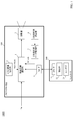
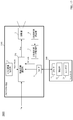
- FIG. 1 is a schematic configuration diagram of a projection system 1000 according to a first embodiment.
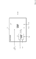
- 1 is a schematic configuration diagram of a projection image adjustment unit 1 of a projector apparatus 100 of a projection system 1000 according to a first embodiment.
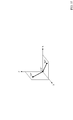
- the figure which showed the three-dimensional space in the state 1 typically.
- FIG. The schematic block diagram of the projection system 1000A which concerns on the 1st modification of 1st Embodiment.
- the schematic block diagram of 1 A of projection image adjustment parts which concern on the 1st modification of 1st Embodiment.
- the schematic block diagram of the projection system 2000 which concerns on 2nd Embodiment.
- the figure which showed three-dimensional space typically.
- the figure which showed the three-dimensional space in the state 1 typically.
- FIG. The figure which shows 2nd test image Img1_T2.
- the figure which showed the three-dimensional space in the state 4 typically.
- FIG. 4 is a flowchart showing a projection method executed by the projection system 2000.
- FIG. The figure for demonstrating the principle of a viewpoint specific process.
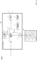
- FIG. 1 is a schematic configuration diagram of a projection system 1000 according to the first embodiment.
- FIG. 2 is a schematic configuration diagram of the projection image adjustment unit 1 of the projector apparatus 100 of the projection system 1000 according to the first embodiment.
- the projection system 1000 includes a projector device 100 and a controller 200 as shown in FIG.
- the projector device 100 includes a projection image adjustment unit 1, a test image storage unit 2, a projection unit 3, a three-dimensional shape measurement unit 4, a three-dimensional shape data storage unit 5, and a first And an interface 6.
- the projection image adjustment unit 1 includes a first selector 11, a correction unit 12, a switch 13, a rotation processing unit 14, a second selector 15, a trapezoidal correction processing unit 16, A third selector 17 and a fourth selector 18.
- the first selector 11 inputs an image Din (image signal Din) input to the projector device 100, a test image Img1 output from the test image storage unit 2, and a selection signal sel1.
- the first selector 11 selects either the image Din or the test image Img1 according to the selection signal sel1, and outputs the selected image (image signal) to the correction unit 12 as an image D1 (image signal D1).
- the selection signal sel1 is a control signal generated by a control unit (not shown) that controls each functional unit of the projector device 100.
- the correction unit 12 inputs the image D1 output from the first selector 11, the three-dimensional shape data 3D_data output from the three-dimensional shape data storage unit 5, and the information P_prj about the projection point of the projection unit 3. .
- the correction unit 12 performs correction processing on the image D1 based on the three-dimensional shape data 3D_data and the information P_prj about the projection point. Then, the correction unit 12 outputs the corrected image as an image D2 (image signal D2) to the second selector 15 and the rotation processing unit 14.
- the switch 13 receives the signal Sig1 output from the first interface 6 and the selection signal sel2.
- the switch 13 outputs the signal Sig1 to the rotation processing unit 14 or the trapezoidal correction processing unit 16 in accordance with the selection signal sel2.
- the selection signal sel2 is a control signal generated by a control unit that controls each functional unit of the projector device 100.
- the rotation processing unit 14 includes an image D2 output from the correction unit 12, three-dimensional shape data 3D_data output from the three-dimensional shape data storage unit 5, information P_prj about the projection point of the projection unit 3, and a switch 13
- the signal Sig1 output from is input.
- the rotation processing unit 14 performs a rotation process on the image D2 based on the three-dimensional shape data 3D_data and the information P_prj about the projection point of the projection unit 3. Then, the rotation processing unit 14 outputs the processed image to the second selector 15 as an image D21 (image signal D21).
- the second selector 15 receives the image D2 output from the correction unit 12, the image D21 output from the rotation processing unit 14, and the selection signal sel3.
- the second selector 15 selects either the image D2 or the image D21 according to the selection signal sel3, and the selected image is set as the image D3 (image signal D3), the trapezoid correction processing unit 16, the third selector 17, Output to.
- the selection signal sel3 is a control signal generated by a control unit that controls each functional unit of the projector device 100.
- the trapezoidal correction processing unit 16 switches the image D3 output from the second selector 15, the three-dimensional shape data 3D_data output from the three-dimensional shape data storage unit 5, and the information P_prj about the projection point of the projection unit 3.
- the signal Sig1 output from the device 13 is input.
- the trapezoid correction processing unit 16 performs the trapezoid correction processing on the image D3 based on the three-dimensional shape data 3D_data and the information P_prj about the projection point of the projection unit 3. Then, the trapezoid correction processing unit 16 outputs the processed image to the third selector 17 as an image D31 (image signal D31).
- the third selector 17 receives the image D3 output from the second selector 15, the image D31 output from the trapezoid correction processing unit 16, and the selection signal sel4.
- the third selector 17 selects one of the image D3 and the image D31 according to the selection signal sel4, and outputs the selected image to the fourth selector 18 as an image D4 (image signal D4).
- the selection signal sel4 is a control signal generated by a control unit that controls each functional unit of the projector device 100.
- the fourth selector 18 inputs the image D4 output from the third selector 17, the test image Img0 output from the test image storage unit 2, and the selection signal sel5.
- the fourth selector 18 selects either the image D4 or the test image Img0 according to the selection signal sel5, and outputs the selected image to the projection unit 3 as an image Dout (image signal Dout).
- the selection signal sel5 is a control signal generated by a control unit that controls each functional unit of the projector device 100.
- the test image storage unit 2 stores a test image, and outputs a test image to the projection image adjustment unit 1 at a predetermined timing in accordance with a request from the projection image adjustment unit 1.
- the projection unit 3 has an optical system for projecting an image.
- the projection unit 3 receives the image Dout (image signal Dout) output from the fourth selector 18 of the projection image adjustment unit 1, and projects the input image Dout (image signal Dout) onto a projection target in a three-dimensional space. .
- the 3D shape measurement unit 4 acquires the 3D measurement data of the projection target in the 3D space, and outputs the acquired 3D measurement data of the projection target to the 3D shape data storage unit 5.
- the three-dimensional shape measurement unit 4 includes, for example, a camera, picks up a three-dimensional shape measurement test image projected from the projection unit 3, and based on the picked-up image of the three-dimensional shape measurement test image. The three-dimensional measurement data to be projected is acquired.
- the three-dimensional shape measurement unit 4 may, for example, (1) obtain a normal line of the projection plane and clarify the positional relationship between the projection unit 3 and the projection plane, or (2) a projection axis (projection unit) of the projection unit 3 3) is obtained, and the positional relationship between the projection unit 3 and the projection plane is clarified, thereby obtaining three-dimensional measurement data of the projection target (projection plane).
- the three-dimensional shape measuring unit 4 acquires three-dimensional measurement data to be projected by acquiring a distance image by a TOF (Time Of Flight) method (for example, a phase difference method of TOF method). Also good.
- the three-dimensional shape measuring unit 4 includes, for example, a light source that emits infrared rays and an image sensor for infrared rays. The reflected infrared rays emitted from the light sources are received by the image sensor and irradiated. The distance image is acquired by measuring the time until the infrared rays are reflected from the projection target and returned. Then, the three-dimensional shape measurement unit 4 acquires the three-dimensional measurement data to be projected from the acquired distance image.
- a TOF Time Of Flight
- the three-dimensional shape measuring unit 4 has a laser light source and a laser sensor, and acquires the three-dimensional measurement data of the projection target by measuring the distance of the projection target from the flight time of the laser light. There may be.
- the three-dimensional shape measuring unit 4 irradiates the laser light on the projection target while sequentially changing the irradiation direction (scanning the projection target with the laser light), and the laser light is reflected on the projection target and returns. By measuring the time until, the distance of the projection target is measured, and the three-dimensional measurement data of the projection target is acquired.
- the 3D shape data storage unit 5 receives the projection target 3D measurement data acquired by the 3D shape measurement unit 4 and stores the input projection target 3D measurement data.
- the three-dimensional shape data storage unit 5 outputs the three-dimensional measurement data to the correction unit 12, the rotation processing unit 14, and the trapezoid correction processing unit 16 in accordance with requests from the correction unit 12, the rotation processing unit 14, and the trapezoid correction processing unit 16. To do.
- the first interface 6 is an interface between the projector device 100 and the controller 200. For example, a signal output from the controller 200 can be input to the projector device 100 via the first interface 6.
- the controller 200 includes a second interface 21, a control unit 22, and a user interface 23.
- the second interface 21 is an interface between the controller 200 and the projector device 100.
- the control unit 22 is a control unit that controls each functional unit of the controller 200.
- the user interface 23 generates a signal corresponding to a user operation. For example, when the user presses a predetermined button provided on the controller, the user interface 23 generates a signal indicating that the button has been pressed.
- the operation of the projection system 1000 will be described assuming that the projection target is the three-dimensional space shown in FIG.
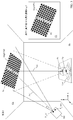
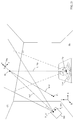
- FIG. 3 is a diagram schematically showing a three-dimensional space, and shows a ceiling CL (horizontal ceiling CL) to be projected, a projector device 100, and a user Usr on the floor FL.
- the ceiling CL horizontal ceiling CL
- the ceiling CL is a plane and is parallel to the floor FL that is a plane.
- the projection point of the projection unit 3 of the projector device 100 is indicated as a point P_prj
- the measurement point of the three-dimensional shape measurement unit 4 of the projector device 100 is indicated as a point P_msr.
- the intersection point between the optical axis (projection axis) Ax1 of the optical system of the projection unit 3 and the horizontal ceiling (plane) CL is defined as a point Pc, and the user's viewpoint position (the center point of both eyes of the user) is set. This is shown as a point Vp.
- an intersection point between a normal line Nm1 of the horizontal ceiling plane CL and a plane parallel to the floor plane FL and including the point Vp is indicated as a point P1.
- the distance between the position of the left eye of the user Usr and the point Pc is equal to the distance between the position of the right eye of the user Usr and the point Pc.
- the 3D shape measurement unit 4 has a camera, takes a test image for 3D shape measurement projected from the projection unit 3, and takes a test image for 3D shape measurement. The case where the three-dimensional measurement data to be projected is acquired based on the captured image will be described.
- the test image Img0 for measuring the three-dimensional shape is output from the test image storage unit 2 to the fourth selector 18 of the projection image adjustment unit 1.
- the control unit generates a selection signal sel 5 for selecting the terminal 0 of the fourth selector 18 shown in FIG. 2 and outputs the selection signal sel 5 to the fourth selector 18. Accordingly, the test image Img0 for measuring the three-dimensional shape is output from the fourth selector 18 to the projection unit 3 as the image signal Dout.
- the projection unit 3 uses the test image Img0 for measuring the three-dimensional shape as (A) the projection axis (the optical axis of the optical system of the projection unit 3) as the axis Ax1 shown in FIG. 3, and (B) the angle of view in FIG. And (C) a projection point is projected as a point P_prj shown in FIG. 3 onto the horizontal ceiling plane CL that is the projection target.
- the 3D shape measurement unit 4 captures the 3D shape measurement test image Img0 projected by the projection unit 3 with the 3D shape measurement camera whose imaging point is the point P_msr. Then, the three-dimensional shape measuring unit 4 acquires the three-dimensional measurement data to be projected by comparing the captured image with the test image Img0 for measuring the three-dimensional shape.
- the coordinates of the three-dimensional space of the projection point P_prj are known, the coordinates of the three-dimensional space of the imaging point P_msr of the three-dimensional shape measurement unit 4 are known, and a test image for three-dimensional shape measurement to be projected Since Img0 is known, the coordinates of the projection target three-dimensional space can be calculated from the image captured at the imaging point P_msr. That is, by examining which pixel of the image captured at the imaging point P_msr corresponds to each pixel of the test image Img0 for measuring the three-dimensional shape, a three-dimensional spatial position corresponding to each pixel (light corresponding to each pixel). Can be identified. Therefore, by specifying the three-dimensional space position corresponding to each pixel, the coordinates of the projection target three-dimensional space can be calculated.
- test image Img0 for three-dimensional shape measurement may be an image formed by a sine wave signal having a predetermined period, for example.
- a plurality of images in which the period and phase of the sine wave signal are changed at a predetermined timing are projected from the projection unit 3 onto the projection target, and the three-dimensional shape measurement unit 4 uses the projected plurality of images, You may make it acquire the three-dimensional shape data of a projection object.
- the 3D shape data to be projected acquired by the 3D shape measurement unit 4 is output from the 3D shape measurement unit 4 to the 3D shape data storage unit 5 and stored in the 3D shape data storage unit 5. Is done.
- the test image Img 1 is output from the test image storage unit 2 to the first selector 11. Then, the control unit generates a selection signal sel1 for selecting the terminal 0 shown in FIG. 2 of the first selector 11, and outputs the selection signal sel1 to the first selector 11. Thereby, the test image Img1 is output from the first selector 11 to the correction unit 12 as the image signal D1.
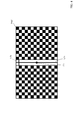
- FIG. 4 shows an example of the test image Img1.
- the test image Img1 includes a first grid pattern that is a white square pattern and a second grid pattern that is a black square pattern in the horizontal direction on the image and on the image. It has a lattice pattern formed by being alternately arranged in the vertical direction.
- the test image Img1 has a center line L1v at the center of the image, a circle C1 at the center point of the image Img1, and a horizontal (horizontal) direction at the top of the image Img1. It is an image of a pattern having a drawn line L1h.
- the portion where the intersection of the line L1v and the line L1h exists is the upper part of the image.
- the test image used for the projection system 1000 is an image that can easily recognize the upper part of the image, such as the test image Img1 shown in FIG. It is preferable that Note that the test image Img1 shown in FIG. 4 is an example, and other images may be used as long as the upper part of the image can be recognized.
- the test image includes a first grid pattern that is a white square pattern and a second grid pattern that is a black square pattern alternately in the horizontal direction on the image and in the vertical direction on the image.
- the lattice pattern formed by being arranged may be provided on the entire surface of the image area, and a specific pattern indicating the upper part of the image may be an image superimposed on a predetermined place of the test pattern image.
- test image Img1 shown in FIG. 4 is used as a test image.
- the correction unit 12 reads the three-dimensional shape data 3D_data from the three-dimensional shape data storage unit 5, and acquires the three-dimensional coordinate data of the horizontal ceiling plane CL that is the projection target. Then, the correction unit 12 displays the image D1 so that the image has no geometric distortion when viewed from the point P1, that is, the point P1 directly below the intersection Pc between the projection axis Ax1 and the ceiling plane CL. Correction processing is performed on Then, the correction unit 12 outputs the corrected image to the second selector 15 as an image D2.
- the control unit generates a selection signal sel3 for selecting the terminal 0 shown in FIG. 2 of the second selector 15 and outputs it to the second selector 15.
- the image D2 is output from the second selector 15 to the third selector 17 as the image D3.
- the control unit generates a selection signal sel4 for selecting the terminal 0 shown in FIG. 2 of the third selector 17 and outputs it to the third selector 17.
- the third selector 17 outputs the image D3 as the image D4 to the fourth selector 18.
- the control unit generates a selection signal sel5 for selecting the terminal 1 shown in FIG. 2 of the fourth selector 18, and outputs the selection signal sel5 to the fourth selector 18. Thereby, the image D4 is output from the fourth selector 18 to the projection unit 3 as the image Dout.
- the projection unit 3 projects the image Dout from the fourth selector 18 onto the horizontal ceiling plane CL by the projection axis Ax1 shown in FIG. This state is referred to as “state 1”.
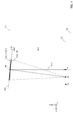
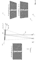
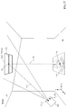
- FIG. 5 shows the horizontal ceiling plane CL in the state 1, the floor FL, the viewpoint Vp of the user Usr, and the intersection Pc between the optical axis (projection axis) Ax1 of the optical system of the projection unit 3 and the horizontal ceiling (plane) CL. , Passing through the point Pc, the normal line Nm1 of the horizontal ceiling plane CL and the intersection point P1 of the plane parallel to the floor plane FL and including the point Vp from the positive x-axis direction to the negative x-axis direction. It is the figure (yz top view) seen.
- L1 indicates a plane parallel to the floor FL and including the viewpoint Vp.
- test image Img1 viewed from the viewpoint Vp in the state 1 is shown as an image Img1 (Vp).
- the test image Img1 viewed from the point P1 (a point directly below the point Pc) is shown as an image Img1 (P1).
- the image Img1 (Vp) viewed from the viewpoint Vp of the user Usr has a geometric distortion but is viewed from the point P1 (a point directly below the point Pc).
- the test image Img1 (P1) has no geometric distortion.
- the rotation process is executed.
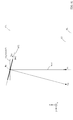
- FIG. 6 is a diagram schematically showing the three-dimensional space in state 1, and is a diagram for explaining the rotation processing.
- the user operates the controller 200 to rotate the image Img1 projected on the horizontal ceiling plane CL in the direction indicated by the arrow Dir1 in FIG. 6 about the point Pc.
- the center line L1v of the image Img1 is made to appear as a vertical straight line when viewed from the user's viewpoint Vp. That is, the user operates the controller 200 so that the center line L1v of the image Img1 is within the plane including the point Pc, the point P1, and the viewpoint Vp, and the image Img1 projected on the horizontal ceiling plane CL is displayed.
- the user rotates the image Img1 so that the upper portion of the image of the image Img1 (the portion where the line L1v and the line L1h of the image Img1 intersect) is the upper portion when viewed from the user.
- the test image Img 1 is output from the test image storage unit 2 to the first selector 11. Then, the control unit generates a selection signal sel1 for selecting the terminal 0 shown in FIG. 2 of the first selector 11, and outputs the selection signal sel1 to the first selector 11. Thereby, the test image Img1 is output from the first selector 11 to the correction unit 12 as the image signal D1.
- the correction unit 12 performs the same correction process as the process executed in the state 1 on the image D1. Then, the correction unit 12 outputs the corrected image to the rotation processing unit 14 as an image D2.
- the user operates the controller 200 to cause the projector device 100 to execute the rotation process.
- the controller 200 has two buttons for performing rotation processing, and when the first button (one button) is pressed once, the test image Img1 is displayed in the left direction of the direction Dir1 in FIG. , A process of rotating the test image Img1 by a predetermined angle to the right of the direction Dir1 in FIG. 6 by pressing the second button (the other button) once. Can be executed.
- the user interface 23 When the first button of the controller 200 is pressed once, the user interface 23 generates a signal indicating that the first button has been pressed once. Based on the signal generated by the user interface 23, the control unit 22 of the controller 200 sends a signal indicating that the first button has been pressed once to the first interface of the projector device 100 via the second interface 21. Send.
- controller 200 can be operated by a user, and the controller 200 and the projector device 100 transmit and receive signals by wireless communication, for example.
- the user operates the controller 200 while holding the controller 200 in his / her hand while viewing the image Img1 projected onto the horizontal ceiling plane CL, and is projected onto the horizontal ceiling plane CL.
- the image Img1 is rotated.
- the first interface 6 of the projector device 100 receives the signal transmitted from the second interface 21 of the controller 200 and outputs the received signal to the switch 13 as the signal Sig1.
- the switch 13 selects the terminal 1 shown in FIG. 2 based on the selection signal sel2 generated by the control unit, and outputs the signal Sig1 to the rotation processing unit 14.
- the rotation processing unit 14 performs a rotation process on the image D2 output from the correction unit 12 based on the signal Sig1, the three-dimensional shape data 3D_data, and the information P_prj about the projection point of the projection unit 3.
- the rotation processing unit 14 views the horizontal ceiling plane CL from the point P1
- the image Img1 is determined by the signal Sig1 around the point Pc in the left direction of the arrow Dir1 illustrated in FIG.
- Conversion processing rotation processing
- the rotation processing unit 14 outputs the processed image to the second selector 15 as an image D21 (image signal D21).
- the second selector 15 selects the terminal 1 shown in FIG. 2 based on the selection signal sel3 generated by the control unit, and outputs the image D21 to the third selector 17 as the image D3.
- the image Img1 is an image rotated in the direction Dir1 by a predetermined angle with the point Pc as the center.
- the center line L1v of the image Img1 is made to appear as a vertical straight line when viewed from the user's viewpoint Vp.
- This state that is, a state in which the center line L1v of the image Img1 is in a plane including the point Pc, the point P1, and the viewpoint Vp is referred to as “state 2”.
- FIG. 7 is a diagram schematically showing a three-dimensional space in state 2.
- the test image Img1 viewed from the user's viewpoint Vp is shown as an image Img1 (Vp).
- the test image Img1 viewed from the point P1 is shown as an image Img1 (P1).
- test image Img1 when viewed from the user's viewpoint Vp, it appears as a trapezoidal image (image Img1 (Vp1)).
- the rotation process is executed as described above, and after the projection state of the projection system 1000 is changed to the state 2, the trapezoidal correction process is executed.
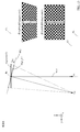
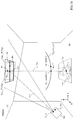
- FIG. 8 is a diagram for explaining the trapezoid correction process.
- 8 shows the horizontal ceiling plane CL, the floor FL, the viewpoint Vp of the user Usr, and the intersection Pc between the optical axis (projection axis) Ax1 of the optical system of the projection unit 3 and the horizontal ceiling (plane) CL in the state 2.
- L1 indicates a plane parallel to the floor FL and including the viewpoint Vp.
- 9 to 13 are diagrams for explaining the trapezoid correction process.
- 9 to 13 show the horizontal ceiling plane CL, the floor FL, the viewpoint Vp of the user Usr, the point Pc, and the intersection P1 from the positive x-axis direction to the negative x-axis direction, as in FIG. It is the figure (yz top view) seen.
- FIG. 14 is a diagram schematically showing a three-dimensional space in the state 3, and is a diagram for explaining a trapezoid correction process.
- the user operates the controller 200 to cause the projector device 100 to execute the keystone correction process on the image Img1 projected on the horizontal ceiling plane CL.
- the keystone correction process is executed by the following processes (1) and (2), for example.
- the image Img1 image Img1 in state 2 (this is the image Img1) projected onto the horizontal ceiling plane CL with the axis passing through the point Pc and parallel to the x axis as the rotation axis. (Denoted as (state2))) is set as a virtual projection plane (for example, virtual projection plane SF1 shown in FIG. 8) obtained by rotating a predetermined angle in the direction Dir2 (clockwise direction) shown in FIG. .
- Rotation processing so that an image without geometric distortion is obtained when viewed from a point on the normal line of the virtual projection plane set as described above (point P2 shown in FIGS. 8 and 9).
- Image conversion processing (trapezoid correction processing) is performed on the subsequent image Img1.
- the test image Img1 is output from the test image storage unit 2 to the first selector 11. Then, the control unit generates a selection signal sel1 for selecting the terminal 0 shown in FIG. 2 of the first selector 11, and outputs the selection signal sel1 to the first selector 11. Thereby, the test image Img1 is output from the first selector 11 to the correction unit 12 as the image signal D1.
- the correction unit 12 performs the same correction process as the process executed in states 1 and 2 on the image D1. Then, the correction unit 12 outputs the corrected image to the rotation processing unit 14 as an image D2.
- Rotation processing unit 14 executes the same rotation process as the process executed in state 2. Then, the rotation processing unit 14 outputs the image D21 after the rotation process is performed on the image D2 to the second selector 15.
- the second selector 15 selects the terminal 1 shown in FIG. 2 based on the selection signal sel3 generated by the control unit, and outputs the image D21 as the image D3 to the trapezoid correction processing unit 16.
- the user operates the controller 200 to cause the projector device 100 to execute a keystone correction process.
- the controller 200 has two buttons for performing keystone correction processing, and by pressing the buttons, for example, the following processes (1) and (2) are executed on the projector device 100.
- (1) By pressing the first button (one button) of the controller 200 once, the horizontal ceiling plane CL is virtually moved to a position rotated by a predetermined angle in the direction Dir2 (clockwise direction) shown in FIG.
- Dir2 clockwise direction
- a plane is set, and image conversion processing (trapezoid correction processing) is executed on the projector device 100 so that there is no geometric distortion when viewed from a point on the normal line of the virtual plane passing through the point Pc.
- the user interface 23 When the first button of the controller 200 is pressed once, the user interface 23 generates a signal indicating that the first button has been pressed once. Based on the signal generated by the user interface 23, the control unit 22 of the controller 200 sends a signal indicating that the first button has been pressed once via the second interface 21 to the first interface 6 of the projector device 100. Send to.
- controller 200 can be operated by a user, and the controller 200 and the projector device 100 transmit and receive signals by wireless communication, for example.
- the user operates the controller 200 while holding the controller 200 in his / her hand and sees the image Img1 projected on the horizontal ceiling plane CL, and is projected onto the horizontal ceiling plane CL.
- a process of reducing the geometric distortion of the image Img1 (trapezoid correction process) is executed.
- the first interface 6 of the projector device 100 receives the signal transmitted from the second interface 21 of the controller 200 and outputs the received signal to the switch 13 as the signal Sig1.
- the switcher 13 selects the terminal 0 shown in FIG. 2 based on the selection signal sel2 generated by the control unit, and outputs the signal Sig1 to the trapezoidal correction processing unit 16.
- the trapezoid correction processing unit 16 performs trapezoid correction processing on the image D3 output from the second selector 15 based on the signal Sig1, the three-dimensional shape data 3D_data, and the information P_prj about the projection point of the projection unit 3. Execute.
- the trapezoidal correction processing unit 16 determines the rotation angle ⁇ 1 when the first button (one button) of the controller 200 is pressed once from the signal Sig1. Then, the trapezoidal correction processing unit 16 sets the virtual plane SF1 at a position obtained by rotating the horizontal ceiling plane CL by the rotation angle ⁇ 1 in the direction Dir2 (clockwise direction) illustrated in FIG. 9, passes through the point Pc, and passes through the virtual plane. Image conversion processing is performed on the image D3 so that there is no geometric distortion of the image projected on the horizontal ceiling plane CL when the horizontal ceiling plane CL is viewed from the point P2 on the normal line of SF1. (Keystone correction processing) is executed. Then, the trapezoid correction processing unit 16 outputs the image after the trapezoid correction processing to the third selector 17 as an image D31.
- the third selector 17 selects the terminal 1 shown in FIG. 2 based on the selection signal sel4 generated by the control unit, and outputs the image D31 to the fourth selector 18 as the image D4.
- the image Img1 is projected as an image without geometric distortion. The state at this time is shown in FIG.
- the image Img_R1_CL shown in FIG. 10 is an image acquired as follows. That is, the image Img_R1_CL is the clockwise direction (direction Dir2) in the yz plane with the image Img (state 2) of the horizontal ceiling plane CL in the state 2 passing through the point Pc and having an axis parallel to the x axis as the rotation axis.
- the image (image Img_R1 in FIG. 10 (image Img_R1 on the virtual plane SF1) in FIG. 10) rotated by an angle ⁇ 1 is projected onto the horizontal ceiling plane CL from a point on the normal line of the virtual plane SF1 (eg, point P2). It is an image acquired by.
- FIG. 10 shows an image Img1 (state 2) when the horizontal ceiling plane CL is viewed from the point Vp in the state 2, and the trapezoid correction process is executed on the lower right side of FIG.
- the image Img1_R1_CL when the horizontal ceiling plane CL is viewed from the point Vp is shown.
- the image Img1_R1_CL shown on the lower right side of FIG. 10 has a reduced geometric distortion (trapezoidal distortion) than the image Img1 (state 2) shown on the upper right side of FIG.
- the user further presses the first button to execute a trapezoidal correction process in which the rotation angle ⁇ 1 shown in FIG. 10 is a larger angle, and the geometrical shape of the image projected on the horizontal ceiling plane CL. Distortion can be further reduced.
- the other button of the controller 200 is displayed.
- the projector device 100 can execute a trapezoid correction process for reducing geometric distortion (trapezoid distortion) of an image projected on the horizontal ceiling plane CL.
- the geometric distortion (trapezoidal distortion) of the image projected on the horizontal ceiling plane CL is reduced by pressing the first button of the controller 200.
- the user further presses the first button to cause the projector device 100 to execute the keystone correction process.
- the trapezoidal correction processing unit 16 executes a trapezoidal correction process in which the rotation angle ⁇ 1 shown in FIG.
- the rotation angle becomes ⁇ 2
- the horizontal ceiling plane CL passes through the point Pc
- the axis parallel to the x axis is the rotation axis.
- the normal line passing through the point Pc of the virtual plane SF2 rotated by the angle ⁇ 2 in the clockwise direction (direction Dir2) in the yz plane will be described as being in a state passing through the user's viewpoint Vp.
- the trapezoidal correction processing unit 16 determines the rotation angle ⁇ 2 when the first button (one button) of the controller 200 is further pressed from the signal Sig1. Then, the trapezoidal correction processing unit 16 sets the virtual plane SF2 at a position obtained by rotating the horizontal ceiling plane CL by the rotation angle ⁇ 2 in the direction Dir2 (clockwise direction) illustrated in FIG. 11, passes through the point Pc, and passes through the virtual plane. Image conversion processing is performed on the image D3 so that there is no geometric distortion of the image projected on the horizontal ceiling plane CL when the horizontal ceiling plane CL is viewed from the point Vp on the normal line of SF2. (Keystone correction processing) is executed. Then, the trapezoid correction processing unit 16 outputs the image after the trapezoid correction processing to the third selector 17 as an image D31.
- state 3 The image D31 generated by the trapezoid correction processing unit 16 in this way is projected onto the horizontal ceiling plane CL by the projection unit 3. This state is referred to as “state 3”.
- the image Img1 is projected as an image without geometric distortion (an image with reduced geometric distortion).
- the state at this time is shown in FIG.
- the image Img_R2_CL shown in FIG. 12 is an image acquired as follows. That is, the image Img_R2_CL is the clockwise direction (direction Dir2) in the yz plane with the image Img (state2) of the horizontal ceiling plane CL in the state 2 passing through the point Pc and having an axis parallel to the x axis as the rotation axis.
- the image (image Img_R2 in FIG. 12 (image Img_R2 on the virtual plane SF2) in FIG. 12) rotated by an angle ⁇ 2 is projected onto the horizontal ceiling plane CL from a point on the normal line of the virtual plane SF2 (for example, the viewpoint Vp). It is an image acquired by.
- the image Img1 (state 3) (image Img1_R2_CL) shown on the lower right side of FIG. 12 has less geometric distortion (trapezoidal distortion) than the image Img1 (state 2) shown on the upper right side of FIG. I understand).
- the user confirms the state (state 3) in which the geometric distortion of the image projected on the horizontal ceiling plane CL is sufficiently reduced, and performs adjustment processing (to reduce the geometric distortion of the image) in the projector device 100. Adjustment processing) is terminated.
- the user operates the controller 200 to end the adjustment process (the adjustment process for reducing the geometric distortion of the image) in the projector device 100.
- the projector device 100 receives from the controller 200 a signal for ending the adjustment processing (adjustment processing for reducing image geometric distortion) in the projector device 100.
- the projector device 100 When the projector apparatus 100 receives the signal from the controller 200, according to the current setting, the projector device 100 performs (1) correction processing by the correction unit 12, (2) rotation processing by the rotation processing unit 14, and (3) trapezoid correction processing unit.
- the adjustment process (the adjustment process for reducing the geometric distortion of the image) is completed in such a manner that the trapezoidal correction process according to 16 is executed.
- the first selector 11 selects the terminal 1 to correct the image signal Din. To the unit 12.
- the projector apparatus 100 is configured to select the terminal 1 in the second selector 15, the terminal 1 in the third selector 17, and the terminal 1 in the fourth selector 18.
- the correction unit 12, the rotation processing unit 14, and the trapezoidal correction processing unit 16 of the projector device 100 are based on the settings when the adjustment processing (adjustment processing for reducing geometric distortion of the image) is completed. Then, a correction process, a rotation process, and a trapezoidal correction process are executed.
- the image (video) after these processes are executed is projected from the projection unit 3 onto the horizontal ceiling plane CL.
- an image (video) obtained by projecting the image Din (or video Din) input to the projector device 100 onto the horizontal ceiling plane CL has no geometric distortion when viewed from the user's viewpoint Vp ( (Reduced) image (video).
- the test image showing the upper part when displayed is projected onto the horizontal ceiling plane CL, and the user performs (1) the process of rotating the projection image within the horizontal ceiling plane CL by the controller 200.
- (2) geometric processing of the image projected on the horizontal ceiling plane CL is performed by causing the projector apparatus 100 to perform trapezoidal correction processing of the image projected on the horizontal ceiling plane CL. Distortion can be eliminated (reduced).
- geometric distortion of an image projected onto a horizontal projection surface (for example, a horizontal ceiling) can be easily and appropriately eliminated (reduced) without using a device having a photographing function. it can.
- FIG. 15 is a schematic configuration diagram of a projection system 1000A according to a first modification of the first embodiment.
- FIG. 16 is a schematic configuration diagram of the projection image adjustment unit 1A of the projector device 100A of the projection system 1000A according to the first modification of the first embodiment.
- the projection system 1000A of the first modification has a configuration in which the projector device 100 is replaced with the projector device 100A in the projection system 1000 of the first embodiment.
- the projector device 100 ⁇ / b> A has a configuration in which a fine adjustment unit 19 is added between the third selector 17 and the fourth selector 18 in the projector device 100.
- the projector device 100 ⁇ / b> A is the same as the projector device 100.
- the fine adjustment unit 19 receives the image D4 output from the third selector 17 and the control signal ctl1 output from the control unit.
- the fine adjustment unit 19 uses the input signal as it is as the signal D4A (image D4A) until the adjustment process (adjustment process for reducing geometric distortion of the image) described in the first embodiment is completed. Output to the fourth selector 18. Then, when the adjustment process (adjustment process for reducing the geometric distortion of the image) is completed, the fine adjustment unit 19 projects the projection projected on the projection plane by the projection unit 3 in accordance with the control signal ctl1 from the control unit. Processing is performed on the image D4 so as to finely move each vertex of the image, and the processed image is output to the fourth selector 18 as an image D4A (image signal D4A).
- the fine adjustment unit 19 retains the setting of the fine adjustment process, and when the projector apparatus 100 is switched to the mode for displaying (projecting) the image signal (or video signal) Din, the input is performed according to the setting. Perform fine adjustment on the signal.
- the fine adjustment process is performed after the same adjustment process (adjustment process for reducing the geometric distortion of the image) as in the projection system of the first embodiment is executed.
- the processing amount (work amount) required to correct the error in the three-dimensional shape measurement process can be dramatically reduced as compared with the prior art.
- control signal ctl1 input to the fine adjustment unit 19 may be a signal based on a user operation by the controller 200.
- the user performs a fine adjustment processing operation using the controller 200, and the controller 200 generates a control signal based on the user operation, and transmits the generated control signal to the projector device 100A.
- the projector device 100A may receive the signal transmitted from the controller 200 as the signal Sig1 via the first interface 6, and use the received signal Sig1 as the control signal ctl1 input to the fine adjustment unit 19.
- FIG. 17 is a schematic configuration diagram of a projection system 2000 according to the second embodiment.
- FIG. 18 is a schematic configuration diagram of the projection image adjustment unit 201 of the projector apparatus 2100 of the projection system 2000 according to the second embodiment.
- FIG. 19 is a schematic configuration diagram of the viewpoint identification processing unit 215 of the projection system 2000 according to the second embodiment.
- FIG. 20 is a schematic configuration diagram of the viewpoint candidate acquisition unit 151 of the projection system 2000 according to the second embodiment.
- the projection system 2000 includes a projector device 2100 and a controller 200 as shown in FIG.
- the projector apparatus 2100 includes a projection image adjustment unit 201, a test image storage unit 2, a projection unit 3, a three-dimensional shape measurement unit 4, a three-dimensional shape data storage unit 5, and a first And an interface 6.
- the projection image adjustment unit 201 includes a first selector SEL1, a first switch SW1, a correction unit 211, a second switch 212, a first rotation processing unit 213, and a second selector.
- SEL2 a second rotation processing unit 214, a third selector SEL3, a viewpoint identification processing unit 215, a fourth selector SEL4, and a fifth selector SEL5.
- the first selector SEL1 inputs an image Din (image signal Din) input to the projector device 2100, a test image Img1 output from the test image storage unit 2, and a selection signal sel1.
- the first selector SEL1 selects either the image Din or the test image Img1 according to the selection signal sel1, and outputs the selected image (image signal) to the first switch SW1 as the image D1 (image signal D1).
- the selection signal sel1 is a control signal generated by a control unit (not shown) that controls each functional unit of the projector device 2100.
- the first switch SW1 receives the image D1 output from the first selector SEL1 and the switching signal sw1.
- the first switch SW1 outputs the image D1 (image signal D1) to any one of the correction unit 211 and the viewpoint identification processing unit 215 in accordance with the switching signal sw1.
- the switching signal sw1 is a control signal generated by a control unit that controls each functional unit of the projector device 2100.
- the correction unit 211 receives the image D1 output from the first switch SW1, the three-dimensional shape data 3D_data output from the three-dimensional shape data storage unit 5, and the information P_prj about the projection point of the projection unit 3. To do. The correction unit 211 performs correction processing on the image D1 based on the three-dimensional shape data 3D_data and the information P_prj about the projection point. Then, the correction unit 211 outputs the corrected image as an image D2 (image signal D2) to the second selector SEL2 and the first rotation processing unit 213.
- the second switch 212 receives the signal Sig1 output from the first interface 6 and the switch signal sw2.
- the second switch 212 outputs the signal Sig1 to any one of the first rotation processing unit 213, the second rotation processing unit 214, and the viewpoint identification processing unit 215 in accordance with the switching signal sw2.
- the switching signal sw2 is a control signal generated by a control unit that controls each functional unit of the projector device 2100.
- the first rotation processing unit 213 includes an image D2 output from the correction unit 211, 3D shape data 3D_data output from the 3D shape data storage unit 5, information P_prj about the projection point of the projection unit 3,
- the signal Sig1 output from the 2 switch 212 is input.
- the first rotation processing unit 213 performs the first rotation processing on the image D2 based on the three-dimensional shape data 3D_data and the information P_prj about the projection point of the projection unit 3. (Details will be described later).
- the first rotation processing unit 213 outputs the processed image to the second selector SEL2 as an image D21 (image signal D21).
- the first rotation processing unit 213 outputs a detection signal including information (detection information) when the first rotation processing is completed to the viewpoint specifying processing unit 215 as Det1 (details will be described later).
- the detection signal Det1 includes first straight line data (first straight line data) (details will be described later).
- the second selector SEL2 inputs the image D2 output from the correction unit 211, the image D21 output from the first rotation processing unit 213, and the selection signal sel2.
- the second selector SEL2 selects either the image D2 or the image D21 in accordance with the selection signal sel2, and uses the selected image as the image D3 (image signal D3), the second rotation processing unit 214, and the third selector SEL3. And output.
- the selection signal sel2 is a control signal generated by a control unit that controls each functional unit of the projector device 2100.
- the second rotation processing unit 214 includes an image D3 output from the second selector SEL2, three-dimensional shape data 3D_data output from the three-dimensional shape data storage unit 5, information P_prj about the projection point of the projection unit 3, and The signal Sig1 output from the second switch 212 is input.
- the second rotation processing unit 214 performs the second rotation processing on the image D3 based on the three-dimensional shape data 3D_data and the information P_prj about the projection point of the projection unit 3. (Details will be described later).
- the second rotation processing unit 214 outputs the processed image to the third selector SEL3 as an image D31 (image signal D31).
- the second rotation processing unit 214 outputs a detection signal including information (detection information) when the first rotation processing is completed to the viewpoint specifying processing unit 215 as Det2 (details will be described later).
- the detection signal Det2 includes second straight line data (second straight line data) (details will be described later).
- the third selector SEL3 receives the image D3 output from the second selector SEL2, the image D31 output from the second rotation processing unit 214, and the selection signal sel3.
- the third selector SEL3 selects one of the image D3 and the image D31 according to the selection signal sel3, and outputs the selected image to the fourth selector SEL4 as an image D4 (image signal D4).
- the selection signal sel3 is a control signal generated by a control unit that controls each functional unit of the projector device 2100.
- the viewpoint identification processing unit 215 includes an image D1 output from the first switch SW1, three-dimensional shape data 3D_data output from the three-dimensional shape data storage unit 5, information P_prj about the projection point of the projection unit 3, and Enter.
- the viewpoint identification processing unit 215 receives the detection signal Det1 output from the first rotation processing unit 213 and the detection signal Det2 output from the second rotation processing unit 214.
- the viewpoint identification processing unit 215 includes a viewpoint candidate acquisition unit 151 and a projection image acquisition unit 152, as shown in FIG.
- the viewpoint candidate acquisition unit 151 includes an intersection calculation unit 1511, a coefficient calculation unit 1512, a transformation matrix acquisition unit 1513, a transformation matrix synthesis unit 1514, an inverse transformation matrix acquisition unit 1515, and a transformation unit. 1516, a coefficient acquisition unit 1517, an angle acquisition unit 1518, and a viewpoint candidate point calculation unit 1519.
- the intersection calculation unit 1511 receives the detection signal Det1 output from the first rotation processing unit 213 and the detection signal Det2 output from the second rotation processing unit 214. Based on the first straight line data included in the detection signal Det1 and the second straight line data included in the detection signal Det2, the intersection calculation unit 1511 calculates the coordinates of the intersection point Pc between the first straight line and the second straight line, The coordinates of a point Pa other than the intersection Pc and the coordinates of a point Pb other than the intersection Pc on the second straight line are calculated, and information on the coordinates of the calculated intersection Pc is obtained.
- the included signal (data) is output to the viewpoint candidate point calculation unit 1519 as Data (Pc).
- intersection calculation unit 1511 outputs a signal (data) including coordinate information of the point Pa as Data (Pa) to the coefficient calculation unit 1512 and the transformation matrix acquisition unit 1513.
- intersection calculation unit 1511 outputs a signal (data) including coordinate information of the point Pb to the coefficient calculation unit 1512 and the conversion unit 1516 as Data (Pb).
- the coefficient calculation unit 1512 inputs the data Data (Pa) of the point Pa and the data Data (Pb) of the point Pb output from the intersection calculation unit 1511.
- the coefficient calculation unit 1512 acquires information about the coefficients A, B, and C based on the data Data (Pa) of the point Pa and the data Data (Pb) of the point Pb (details will be described later). Then, the coefficient calculation unit 1512 outputs information (data) about the acquired coefficients A, B, and C to the transformation matrix acquisition unit 1513.
- the transformation matrix acquisition unit 1513 receives information (data) on the coefficients A, B, and C output from the coefficient calculation unit 1512 and data Data (Pa) of the point Pa output from the intersection calculation unit 1511. .
- the transformation matrix acquisition unit 1513 acquires transformation matrices Rx, Ry, and Rz based on the coefficients A, B, and C and the data Data (Pa) of the point Pa. Then, the transformation matrix acquisition unit 1513 outputs data about the obtained transformation matrices Rx, Ry, and Rz to the transformation matrix synthesis unit 1514.
- the transformation matrix synthesis unit 1514 receives the data about the transformation matrices Rx, Ry, Rz output from the transformation matrix acquisition unit 1513, and obtains the synthesis matrix R from the transformation matrices Rx, Ry, Rz. Then, the transformation matrix synthesis unit 1514 outputs the acquired data about the synthesis matrix R to the inverse transformation matrix acquisition unit 1515 and the transformation unit 1516.
- the inverse transformation matrix acquisition unit 1515 receives data regarding the synthesis matrix R output from the transformation matrix synthesis unit 1514.
- the inverse transformation matrix acquisition unit 1515 acquires the inverse transformation matrix R ⁇ 1 from the synthesis matrix R, and outputs data on the obtained inverse transformation matrix R ⁇ 1 to the viewpoint candidate point calculation unit 1519.
- the conversion unit 1516 receives data about the synthesis matrix R output from the conversion matrix synthesis unit 1514 and data Data (Pb) of the point Pb output from the intersection calculation unit 1511.
- the conversion unit 1516 acquires data (coordinate data) about the point Pb ′ as Data (Pb ′) from the synthesis matrix R and the data Data (Pb) of the point Pb. Then, the conversion unit 1516 outputs the acquired data Data (Pb ′) to the coefficient acquisition unit 1517 and the viewpoint candidate point calculation unit 1519.
- the coefficient acquisition unit 1517 receives data Data (Pb ′) output from the conversion unit 1516 and data about the angle ⁇ output from the angle acquisition unit 1518.
- the coefficient acquisition unit 1517 acquires the coefficient A ′ based on the data Data (Pb ′) and the angle ⁇ . Then, the coefficient acquisition unit 1517 outputs data on the acquired coefficient A ′ to the viewpoint candidate point calculation unit 1519.
- the angle acquisition unit 1518 receives the signal Sig1 output from the first interface 6, and acquires the angle ⁇ based on the signal Sig1. Then, the angle acquisition unit 1518 outputs data regarding the acquired angle ⁇ to the coefficient acquisition unit 1517 and the viewpoint candidate point calculation unit 1519.
- the viewpoint candidate point calculation unit 1519 receives data Data (Pc) output from the intersection calculation unit 1511 and data about the angle ⁇ output from the angle acquisition unit 1518. Further, the viewpoint candidate point calculation unit 1519 outputs data on the coefficient A ′ output from the coefficient acquisition unit 1517, data Data (Pb ′) output from the conversion unit 1516, and the inverse transformation matrix acquisition unit 1515. The data about the inverse transformation matrix R ⁇ 1 is input.
- the viewpoint candidate point calculation unit 1519 generates viewpoint candidate point coordinate data Vp_cand based on the data Data (Pc), the angle ⁇ , the coefficient A ′, the data Data (Pb ′), and the inverse transformation matrix R ⁇ 1. To get. Then, the viewpoint candidate point calculation unit 1519 outputs the acquired coordinate data Vp_cand of the viewpoint candidate point to the projection image acquisition unit 152.
- the projection image acquisition unit 152 is the coordinate data of the image D1 (test image Img1 (Img1_T3)) output from the first switch SW1 and the viewpoint candidate point output from the viewpoint candidate point calculation unit 1519 of the viewpoint candidate acquisition unit 151. Vp_cand is input. Further, the projection image acquisition unit 152 receives the three-dimensional shape data 3D_data output from the three-dimensional shape data storage unit 5 and information P_prj about the projection point of the projection unit 3. Based on the three-dimensional shape data 3D_data and the information P_prj about the projection point of the projection unit 3, the projection image acquisition unit 152 selects the image D1 (test image Img1 (Img1_T3)) as a viewpoint candidate identified by the coordinate data Vp_cand. When viewed from a point, the image is converted into an image in which no geometric distortion occurs, and the converted image is output to the fourth selector SEL4 as an image D41 (image signal D41).
- the fourth selector SEL4 receives the image D4 output from the third selector SEL3, the image D41 output from the viewpoint identification processing unit 215, and the selection signal sel4.
- the fourth selector SEL4 selects either the image D4 or the image D41 according to the selection signal sel4, and outputs the selected image as the image D5 (image signal D5) to the fifth selector SEL5.
- the selection signal sel4 is a control signal generated by a control unit that controls each functional unit of the projector device 2100.
- the fifth selector SEL5 inputs the image D5 output from the fourth selector SEL4, the test image Img0 for three-dimensional shape measurement output from the test image storage unit 2, and the selection signal sel5.
- the fifth selector SEL5 selects either the image D5 or the test image Img0 according to the selection signal sel5, and outputs the selected image to the projection unit 3 as an image Dout (image signal Dout).
- the selection signal sel5 is a control signal generated by a control unit that controls each functional unit of the projector device 2100.
- the test image storage unit 2 stores a test image, and outputs a test image to the projection image adjustment unit 201 at a predetermined timing in accordance with a request from the projection image adjustment unit 201.
- the projection unit 3 has an optical system for projecting an image.
- the projection unit 3 receives the image Dout (image signal Dout) output from the fifth selector SEL5 of the projection image adjustment unit 201, and projects the input image Dout (image signal Dout) onto a projection target in a three-dimensional space. .
- the 3D shape measurement unit 4 acquires the 3D measurement data of the projection target in the 3D space, and outputs the acquired 3D measurement data of the projection target to the 3D shape data storage unit 5.
- the three-dimensional shape measurement unit 4 includes, for example, a camera, picks up a three-dimensional shape measurement test image projected from the projection unit 3, and based on the picked-up image of the three-dimensional shape measurement test image. The three-dimensional measurement data to be projected is acquired.
- the three-dimensional shape measurement unit 4 may, for example, (1) obtain a normal line of the projection plane and clarify the positional relationship between the projection unit 3 and the projection plane, or (2) a projection axis (projection unit) of the projection unit 3 3) is obtained, and the positional relationship between the projection unit 3 and the projection plane is clarified, thereby obtaining three-dimensional measurement data of the projection target (projection plane).
- the three-dimensional shape measuring unit 4 acquires three-dimensional measurement data to be projected by acquiring a distance image by a TOF (Time Of Flight) method (for example, a phase difference method of TOF method). Also good.
- the three-dimensional shape measuring unit 4 includes, for example, a light source that emits infrared rays and an image sensor for infrared rays. The reflected infrared rays emitted from the light sources are received by the image sensor and irradiated. The distance image is acquired by measuring the time until the infrared rays are reflected from the projection target and returned. Then, the three-dimensional shape measurement unit 4 acquires the three-dimensional measurement data to be projected from the acquired distance image.
- a TOF Time Of Flight
- the three-dimensional shape measuring unit 4 has a laser light source and a laser sensor, and acquires the three-dimensional measurement data of the projection target by measuring the distance of the projection target from the flight time of the laser light. There may be.
- the three-dimensional shape measuring unit 4 irradiates the laser light on the projection target while sequentially changing the irradiation direction (scanning the projection target with the laser light), and the laser light is reflected on the projection target and returns. By measuring the time until, the distance of the projection target is measured, and the three-dimensional measurement data of the projection target is acquired.
- the 3D shape data storage unit 5 receives the projection target 3D measurement data acquired by the 3D shape measurement unit 4 and stores the input projection target 3D measurement data.
- the three-dimensional shape data storage unit 5 receives the three-dimensional measurement data from the correction unit 211, the first rotation processing unit 213, and the viewpoint specifying process in accordance with requests from the correction unit 211, the first rotation processing unit 213, and the viewpoint specifying processing unit 215. To the unit 215.
- the first interface 6 is an interface between the projector device 2100 and the controller 200. For example, a signal output from the controller 200 can be input to the projector device 2100 via the first interface 6.
- the controller 200 includes a second interface 21, a control unit 22, and a user interface 23.
- the second interface 21 is an interface between the controller 200 and the projector device 2100.
- the control unit 22 is a control unit that controls each functional unit of the controller 200.
- the user interface 23 generates a signal corresponding to a user operation. For example, when the user presses a predetermined button provided on the controller, the user interface 23 generates a signal indicating that the button has been pressed.
- processing executed by the projection system 2000 includes (1) three-dimensional shape measurement processing, (2) correction processing, (3) first rotation processing, (4) second rotation processing, and (5) viewpoint.
- the description will be divided into specific processing.
- the operation of the projection system 2000 will be described assuming that the projection target is the three-dimensional space shown in FIG.
- FIG. 21 is a diagram schematically showing a three-dimensional space, and shows a ceiling CL (inclined ceiling CL) to be projected, a projector device 2100, and a user Usr on the floor FL.
- a-axis, b-axis, and c-axis are set.
- the inclined ceiling CL is a plane, and is inclined by an angle ⁇ shown in FIG.
- the projection point of the projection unit 3 of the projector apparatus 2100 is shown as a point P_prj
- the measurement point of the three-dimensional shape measurement unit 4 of the projector apparatus 2100 is shown as a point P_msr.
- the intersection point between the optical axis (projection axis) Ax1 of the optical system of the projection unit 3 and the inclined ceiling CL is a point Pc
- the user's viewpoint position (the center point of both eyes of the user) is a point Vp. Show.
- the inclined ceiling CL is not limited to the case where the inclined ceiling CL is a plane rotated about the rotation axis as the b axis with respect to the plane (ab plane) parallel to the floor FL as described above.
- the inclined ceiling CL coincides with a plane that is rotated by an angle ⁇ with respect to a plane (ab plane) parallel to the floor FL and rotated by an angle ⁇ with the rotation axis as the b axis. It may be a flat surface.
- the center point of the user's left eye (left eye viewpoint) and the center point of the right eye (right eye viewpoint) are on a straight line parallel to the a axis.
- the x axis, the y axis, and the z axis are set. That is, the x axis and the y axis are set so that the optical axis Ax1 of the optical system of the projection unit 3 and the z axis coincide with each other and the normal line of the xy plane is parallel to the z axis. As shown in FIG. 21, the origin Org of the xyz coordinate is assumed to be on the optical axis Ax1.
- FIG. 21 a normal line Nm1 of the inclined ceiling plane CL passing through the point Pc and a point P1 on the normal line Nm1 are shown.
- the three-dimensional shape measurement unit 4 has a camera, takes a test image for three-dimensional shape measurement projected from the projection unit 3, and takes a test image for three-dimensional shape measurement. The case where the three-dimensional measurement data to be projected is acquired based on the captured image will be described.
- the test image storage unit 2 outputs the test image Img0 for measuring the three-dimensional shape to the fifth selector SEL5 of the projection image adjustment unit 201.
- the control unit generates a selection signal sel5 for selecting the terminal 0 shown in FIG. 18 of the fifth selector SEL5, and outputs the selection signal sel5 to the fifth selector SEL5.
- the test image Img0 for measuring the three-dimensional shape is output from the fifth selector SEL5 to the projection unit 3 as the image signal Dout.
- the projection unit 3 sets the test image Img0 for measuring the three-dimensional shape as (A) the projection axis (the optical axis of the optical system of the projection unit 3) as the axis Ax1 shown in FIG. And (C) a projection point is projected as a point P_prj shown in FIG. 21 onto the inclined ceiling plane CL that is the projection target.
- the 3D shape measurement unit 4 captures the 3D shape measurement test image Img0 projected by the projection unit 3 with the 3D shape measurement camera whose imaging point is the point P_msr. Then, the three-dimensional shape measuring unit 4 acquires the three-dimensional measurement data to be projected by comparing the captured image with the test image Img0 for measuring the three-dimensional shape.
- the coordinates of the three-dimensional space of the projection point P_prj are known, the coordinates of the three-dimensional space of the imaging point P_msr of the three-dimensional shape measurement unit 4 are known, and a test image for three-dimensional shape measurement to be projected Since Img0 is known, the coordinates of the projection target three-dimensional space can be calculated from the image captured at the imaging point P_msr. That is, by examining which pixel of the image captured at the imaging point P_msr corresponds to each pixel of the test image Img0 for measuring the three-dimensional shape, a three-dimensional spatial position corresponding to each pixel (light corresponding to each pixel). Can be identified. Therefore, by specifying the three-dimensional space position corresponding to each pixel, the coordinates of the projection target three-dimensional space can be calculated.
- test image Img0 for three-dimensional shape measurement may be an image formed by a sine wave signal having a predetermined period, for example.
- a plurality of images formed by a sine wave signal whose period and phase are shifted by a predetermined amount over a plurality of times are projected from the projection unit 3 onto the projection target, and the projected plurality of images
- the shape measuring unit 4 may acquire three-dimensional shape data to be projected.
- the 3D shape data to be projected acquired by the 3D shape measurement unit 4 is output from the 3D shape measurement unit 4 to the 3D shape data storage unit 5 and stored in the 3D shape data storage unit 5. Is done.
- the test image Img1 is output from the test image storage unit 2 to the first selector SEL1. Then, the control unit generates a selection signal sel1 for selecting the terminal 0 shown in FIG. 18 of the first selector SEL1, and outputs the selection signal sel1 to the first selector SEL1. As a result, the test image Img1 is output from the first selector SEL1 to the first switch SW1 as the image signal D1.
- FIG. 22 shows a first test image Img1_T1 which is an example of the test image Img1.
- the first test image Img1_T1 is a rectangular image.
- the first test image Img1_T1 has a vertical center line L1v extending in the vertical direction (vertical direction) at the center in the horizontal direction (horizontal direction) of the image, and the horizontal direction ( It is an image of a pattern having a line L2h drawn in the horizontal direction.
- the portion where the intersection of the line L1v and the line L2h exists is the upper part of the image.
- the upper part of the image is used as the test image used in the projection system 2000 as in the first test image Img1_T1 shown in FIG. It is preferable to make the image easy to recognize.
- the first test image Img1_T1 shown in FIG. 22 is an example, and other images may be used as long as the upper part of the image can be recognized.
- the correction unit 211 reads the three-dimensional shape data 3D_data from the three-dimensional shape data storage unit 5 and acquires the three-dimensional coordinate data of the inclined ceiling plane CL that is the projection target. Then, the correction unit 211 acquires the image so as to obtain an image having no geometric distortion when viewed from the point P1, that is, the point P1 on the normal line of the intersection point Pc between the projection axis Ax1 and the ceiling plane CL. Correction processing is performed on the image D1 using the three-dimensional coordinate data of the inclined ceiling plane CL. Then, the correction unit 211 outputs the corrected image as the image D2 to the second selector SEL2.
- the control unit generates a selection signal sel2 for selecting the terminal 0 shown in FIG. 18 of the second selector SEL2, and outputs it to the second selector SEL2.
- the image D2 is output from the second selector SEL2 to the third selector SEL3 as the image D3.
- the control unit generates a selection signal sel3 for selecting the terminal 0 of the third selector SEL3 shown in FIG. 18, and outputs the selection signal sel3 to the third selector SEL3.
- the image D3 is output from the third selector SEL3 as the image D4 to the fourth selector SEL4.
- the control unit generates a selection signal sel4 for selecting the terminal 1 shown in FIG. 18 of the fourth selector SEL4, and outputs it to the fourth selector SEL4.
- the image D4 is output from the fourth selector SEL4 to the fifth selector SEL5 as the image D5.
- the control unit generates a selection signal sel5 for selecting the terminal 1 shown in FIG. 18 of the fifth selector SEL5 and outputs it to the fifth selector SEL5. Thereby, the image D5 is output from the fifth selector SEL5 to the projection unit 3 as the image Dout.
- the projection unit 3 projects the image Dout from the fifth selector SEL5 onto the inclined ceiling plane CL with the projection axis Ax1 shown in FIG. This state is referred to as “state 1”.
- FIG. 23 is a diagram schematically showing a three-dimensional space in state 1. Specifically, FIG. 23 is a diagram schematically illustrating a state in which the first test image Img1_T1 illustrated in FIG. 22 is projected onto the inclined ceiling plane CL. In FIG. 23, in the state 1, the first test image Img1_T1 viewed from the user's viewpoint Vp is shown as an image Img1_T1 (Vp). In FIG. 23, in the state 1, the first test image Img1_T1 viewed from the point P1 is shown as an image Img1_T1 (P1).
- the first test image Img1_T1 (Vp) viewed from the user's viewpoint Vp has a geometric distortion, but the first test image Img1_T1 (P1) viewed from the point P1. It can be seen that no geometric distortion has occurred (geometric distortion has hardly occurred).
- the first rotation process is executed.
- the user operates the controller 200 to display the image Img1_T1 projected on the inclined ceiling plane CL with the arrow P in FIG. 23 centered on the point Pc in the inclined ceiling plane CL.
- the vertical center line L1v of the image Img1_T1 is seen as a vertical straight line when viewed from the user's viewpoint Vp.
- the user operates the controller 200 so that the plane including the vertical center line L1v, the point Pc, and the viewpoint Vp of the image Img1_T1 and the straight line connecting the two eyes of the user are orthogonal to each other, and the inclined ceiling plane CL
- the image Img1_T1 projected on is rotated around the point Pc in the inclined ceiling plane CL in the direction indicated by the arrow Dir1 in FIG.
- the user rotates the image Img1_T1 so that the upper part of the image Img1_T1 (the part where the line L1v and the line L2h of the image Img1_T1 intersect) is the upper part when viewed from the user.
- the first rotation process will be specifically described.
- the test image Img1_T1 is output from the test image storage unit 2 to the first selector SEL1. Then, the control unit generates a selection signal sel1 for selecting the terminal 0 shown in FIG. 18 of the first selector SEL1, and outputs the selection signal sel1 to the first selector SEL1. Thus, the test image Img1_T1 is output from the first selector SEL1 to the first switch SW1 as the image signal D1.
- the control unit generates a switching signal sw1 for selecting the terminal 1 shown in FIG. 18 of the first switch SW1 and outputs it to the first switch SW1. Accordingly, the test image Img1_T1 is output from the first switch SW1 to the correction unit 211 as the image signal D1.
- the correction unit 211 performs the same correction process as the process executed in the state 1 on the image D1. Then, the correction unit 211 outputs the corrected image as the image D2 to the first rotation processing unit 213.
- the user operates the controller 200 to cause the projector device 2100 to execute the first rotation process.
- the controller 200 has two buttons for performing the first rotation process.
- the test image Img1_T1 is displayed in the inclined ceiling plane CL.
- the test image Img1_T1 is displayed in the inclined ceiling plane CL by executing a process of rotating a predetermined angle to the left of the direction Dir1 in FIG. 23 and pressing the second button (the other button) once. It is possible to execute a process of rotating a predetermined angle in the right direction of 23 directions Dir1.
- the user interface 23 When the first button of the controller 200 is pressed once, the user interface 23 generates a signal indicating that the first button has been pressed once. Based on the signal generated by the user interface 23, the control unit 22 of the controller 200 sends a signal indicating that the first button has been pressed once to the first interface of the projector device 2100 via the second interface 21. Send.
- controller 200 can be operated by being held by a user, and the controller 200 and the projector device 2100 transmit and receive signals by, for example, wireless communication.
- the user operates the controller 200 while holding the controller 200 in his / her hand while viewing the image Img1_T1 projected onto the inclined ceiling plane CL, and is projected onto the inclined ceiling plane CL.
- the image Img1_T1 is rotated.
- the first interface of the projector apparatus 2100 receives the signal transmitted from the second interface of the controller 200, and outputs the received signal to the second switch 212 as the signal Sig1.
- the second switch 212 selects the terminal A shown in FIG. 18 based on the switching signal sw2 generated by the control unit, and outputs the signal Sig1 to the first rotation processing unit 213.
- the first rotation processing unit 213 performs first rotation processing on the image D2 output from the correction unit 211 based on the signal Sig1, the three-dimensional shape data 3D_data, and the information P_prj about the projection point of the projection unit 3. Execute.
- the first rotation processing unit 213 does not use the three-dimensional shape data 3D_data and the information P_prj about the projection point of the projection unit 3 and outputs the image D2 output from the correction unit 211 based on the signal Sig1. Then, the first rotation process may be executed. In this case, the three-dimensional shape data 3D_data and the information P_prj about the projection point of the projection unit 3 may not be input to the first rotation processing unit 213.
- the first rotation processing unit 213 looks at the inclined ceiling plane CL from the point P1, the image Img1_T1 is centered on the point Pc in the inclined ceiling plane CL, and the arrow Dir1 illustrated in FIG. Conversion processing (first rotation processing) is performed on the image D2 so that the image is rotated by a predetermined angle determined by the signal Sig1 in the left direction. Then, the first rotation processing unit 213 outputs the processed image to the second selector SEL2 as an image D21 (image signal D21).
- the second selector SEL2 selects the terminal 1 shown in FIG. 18 based on the selection signal sel2 generated by the control unit, and outputs the image D21 as the image D3 to the third selector SEL3.
- the image Img1_T1 is an image rotated in the direction Dir1 by a predetermined angle with the point Pc as the center.
- the vertical center line L1v of the image Img1_T1 is seen as a vertical straight line when viewed from the user's viewpoint Vp.
- This state that is, a state in which the plane including the vertical center line L1v, the point Pc, and the viewpoint Vp of the image Img1_T1 is orthogonal to a straight line connecting both eyes of the user is referred to as “state 2”.
- FIG. 24 is a diagram schematically showing a three-dimensional space in state 2.
- the test image Img1_T1 viewed from the user's viewpoint Vp is shown as an image Img1_T1 (Vp).
- the 1st rotation process part 213 acquires the data for specifying the straight line containing the vertical centerline L1v in the state 2, and hold
- data for specifying a straight line including the vertical center line L1v for example, (1) data of an equation (linear equation) that defines the straight line and (2) coordinates of two different points included in the straight line are specified. There are data for that.
- the first rotation processing unit 213 outputs a detection signal including data for specifying a straight line including the vertical center line L1v to the viewpoint specifying processing unit 215 as Det1.
- the second rotation process is executed.
- FIG. 25 is a diagram illustrating a second test image Img1_T2 that is an example of the test image Img1 used for the second rotation process.
- FIG. 26 is a view for explaining the second rotation process, and is a view (front view) of a three-dimensional space including the inclined ceiling plane CL from the b-axis positive direction toward the negative direction.
- the correction process is executed in the same manner as described above with the input image as the second test image Img1_T2. That is, the following processing is executed.
- the second test image Img1_T2 is output from the test image storage unit 2 to the first selector SEL1. Then, the control unit generates a selection signal sel1 for selecting the terminal 0 shown in FIG. 18 of the first selector SEL1, and outputs the selection signal sel1 to the first selector SEL1. Thereby, the test image Img1_T2 is output from the first selector SEL1 to the first switch SW1 as the image signal D1.
- the second test image Img1_T2 is a rectangular image. Then, as shown in FIG. 25, the second test image Img1_T2 is an image having a pattern having a horizontal center line L1h extending in the horizontal direction (horizontal direction) at the center in the vertical direction (vertical direction) of the image.
- the second test image Img1_T2 illustrated in FIG. 25 is an example, and is not limited to the image illustrated in FIG. 25, and may be another image that can recognize the horizontal distortion of the image. Good.
- the correction unit 211 reads the three-dimensional shape data 3D_data from the three-dimensional shape data storage unit 5 and acquires the three-dimensional coordinate data of the inclined ceiling plane CL that is the projection target. Then, the correction unit 211 acquires the image so as to obtain an image having no geometric distortion when viewed from the point P1, that is, the point P1 on the normal line of the intersection point Pc between the projection axis Ax1 and the ceiling plane CL. Correction processing is performed on the image D1 using the three-dimensional coordinate data of the inclined ceiling plane CL. Then, the correction unit 211 outputs the corrected image as the image D2 to the second selector SEL2.
- the control unit generates a selection signal sel2 for selecting the terminal 0 shown in FIG. 18 of the second selector SEL2, and outputs it to the second selector SEL2.
- the image D2 is output from the second selector SEL2 to the third selector SEL3 as the image D3.
- the control unit generates a selection signal sel3 for selecting the terminal 0 of the third selector SEL3 shown in FIG. 18, and outputs the selection signal sel3 to the third selector SEL3.
- the image D3 is output from the third selector SEL3 as the image D4 to the fourth selector SEL4.
- the control unit generates a selection signal sel4 for selecting the terminal 1 shown in FIG. 18 of the fourth selector SEL4, and outputs it to the fourth selector SEL4.
- the image D4 is output from the fourth selector SEL4 to the fifth selector SEL5 as the image D5.
- the control unit generates a selection signal sel5 for selecting the terminal 1 shown in FIG. 18 of the fifth selector SEL5 and outputs it to the fifth selector SEL5. Thereby, the image D5 is output from the fifth selector SEL5 to the projection unit 3 as the image Dout.
- the projection unit 3 projects the image Dout from the fifth selector SEL5 onto the inclined ceiling plane CL with the projection axis Ax1 shown in FIG. This state is referred to as “state 3”.
- FIG. 26 is a diagram schematically showing a three-dimensional space in state 3. Specifically, FIG. 26 is a diagram schematically illustrating a state in which the second test image Img1_T2 illustrated in FIG. 25 is projected onto the inclined ceiling plane CL.
- the second test image Img1_T2 viewed from the user's viewpoint Vp is shown as an image Img1_T2 (Vp).
- the second test image Img1_T2 viewed from the point P1 is shown as an image Img1_T2 (P1).
- the second rotation process is executed.
- the user operates the controller 200 to rotate the image Img1_T2 projected on the inclined ceiling plane CL around the point Pc in the direction indicated by the arrow Dir2 in FIG.
- the horizontal center line L1h of the image Img1_T2 is made to appear as a horizontal straight line when viewed from the user's viewpoint Vp.
- the second rotation process will be specifically described.
- the second test image Img1_T2 is output from the test image storage unit 2 to the first selector SEL1. Then, the control unit generates a selection signal sel1 for selecting the terminal 0 shown in FIG. 18 of the first selector SEL1, and outputs the selection signal sel1 to the first selector SEL1. Accordingly, the second test image Img1_T2 is output from the first selector SEL1 to the first switch SW1 as the image signal D1.
- the control unit generates a switching signal sw1 for selecting the terminal 1 shown in FIG. 18 of the first switch SW1 and outputs it to the first switch SW1.
- the second test image Img1_T2 is output from the first switch SW1 to the correction unit 211 as the image signal D1.
- the correction unit 211 performs the same correction process as the process executed in the state 3 on the image D1. Then, the correction unit 211 outputs the corrected image as the image D2 to the second selector SEL2.
- the control unit generates a selection signal sel2 for selecting the terminal 0 shown in FIG. 18 of the second selector SEL2, and outputs it to the second selector SEL2.
- the second test image Img1_T2 is output from the second selector SEL2 to the second rotation processing unit 214 as the image signal D3.
- the user operates the controller 200 to cause the projector device 2100 to execute the second rotation process.
- the controller 200 has two buttons for performing the second rotation process, and when the first button (one button) is pressed once, the second test image Img1_T2 is displayed on the inclined ceiling plane CL. , The second test image Img1_T2 is displayed on the inclined ceiling plane CL by executing a process of rotating a predetermined angle to the left of the direction Dir2 in FIG. 26 and pressing the second button (the other button) once. Inside, a process of rotating a predetermined angle to the right of the direction Dir2 in FIG. 26 can be executed.
- the user interface 23 When the first button of the controller 200 is pressed once, the user interface 23 generates a signal indicating that the first button has been pressed once. Based on the signal generated by the user interface 23, the control unit 22 of the controller 200 sends a signal indicating that the first button has been pressed once to the first interface of the projector device 2100 via the second interface 21. Send.
- controller 200 can be operated by being held by a user, and the controller 200 and the projector device 2100 transmit and receive signals by, for example, wireless communication.
- the user operates the controller 200 while holding the controller 200 in his / her hand while viewing the image Img1_T2 projected onto the inclined ceiling plane CL, and is projected onto the inclined ceiling plane CL.
- the image Img1_T2 is rotated.
- the first interface of the projector apparatus 2100 receives the signal transmitted from the second interface of the controller 200, and outputs the received signal to the second switch 212 as the signal Sig1.
- the second switch 212 selects the terminal B shown in FIG. 18 based on the switching signal sw2 generated by the control unit, and outputs the signal Sig1 to the second rotation processing unit 214.
- the second rotation processing unit 214 performs the second rotation on the image D3 output from the second selector SEL2 based on the signal Sig1, the three-dimensional shape data 3D_data, and the information P_prj about the projection point of the projection unit 3. Execute the process.
- the second rotation processing unit 214 does not use the three-dimensional shape data 3D_data and the information P_prj about the projection point of the projection unit 3 and outputs the image D3 output from the correction unit 211 based on the signal Sig1. Then, the second rotation process may be executed. In this case, the three-dimensional shape data 3D_data and the information P_prj about the projection point of the projection unit 3 may not be input to the second rotation processing unit 214.
- the second rotation processing unit 214 views the inclined ceiling plane CL from the point P1
- the image Img1_T2 is centered on the point Pc in the inclined ceiling plane CL
- the arrow Dir2 illustrated in FIG. Conversion processing (second rotation processing) is performed on the image D3 so that the image is rotated in a counterclockwise direction by a predetermined angle determined by the signal Sig1.
- the second rotation processing unit 214 outputs the processed image to the third selector SEL3 as an image D31 (image signal D31).
- the third selector SEL3 selects the terminal 1 shown in FIG. 18 based on the selection signal sel3 generated by the control unit, and outputs the image D31 as the image D4 to the fourth selector SEL4.
- the fourth selector SEL4 selects the terminal 1 shown in FIG. 18 based on the selection signal sel4 generated by the control unit, and outputs the image D4 as the image D5 to the fifth selector SEL5.
- the image Img1_T2 is an image rotated about the point Pc in the direction Dir2 by a predetermined angle.
- the horizontal center line L1h of the image Img1_T2 is seen as a horizontal straight line when viewed from the user's viewpoint Vp.
- This state that is, the state in which the horizontal center line L1h of the image Img1_T2 and the straight line connecting both eyes of the user are parallel is referred to as “state 4”.
- FIG. 27 is a diagram schematically showing a three-dimensional space in state 4.
- the second rotation processing unit 214 acquires and holds data for specifying a straight line including the horizontal center line L1h in the state 4.
- data for specifying a straight line including the horizontal center line L1h for example, (1) data of an equation that defines the straight line (linear equation) or (2) coordinates of two different points included in the straight line are specified. There are data for that.
- the second rotation processing unit 214 outputs a detection signal including data for specifying a straight line including the horizontal center line L1h to the viewpoint specifying processing unit 215 as Det2.
- the viewpoint specifying process is executed.
- FIG. 28 is a diagram for explaining the viewpoint specifying process. Specifically, FIG. 28 shows a test image Img1_T2 (Img1_T2 (Vp)) projected on the inclined ceiling plane CL in the state 4 and a test image Img1_T1 (projected on the inclined ceiling plane CL in the state 2. It is the figure which superimposed and showed Img1_T1 (Vp)).
- state 4A The state shown in FIG. 28 is referred to as “state 4A”.
- FIG. 28 a viewpoint candidate curve Vp_cand_crv indicating a viewpoint candidate point is illustrated.
- the intersection calculation unit 1511 of the viewpoint candidate acquisition unit 151 acquires the first straight line data from the detection signal Det1 output from the first rotation processing unit 213, and is on the straight line including the vertical center line L1v in the state 4A (first The coordinate data Data (Pa) of the point Pa on the straight line is acquired.
- intersection calculation unit 1511 acquires data of the second straight line from the detection signal Det2 output from the second rotation processing unit 214, and is on a straight line (on the second straight line) including the horizontal center line L1h in the state 4A.
- the coordinate data Data (Pb) of the point Pb is acquired.
- the intersection calculation unit 1511 acquires coordinate data Data (Pc) of the intersection Pc of the first straight line and the second straight line. For example, the intersection calculation unit 1511 obtains a linear equation of the first straight line and a linear equation of the second straight line, and calculates the first linear equation from the first straight line and the linear equation of the second straight line by calculating the first linear equation.
- the intersection calculation unit 1511 acquires the coordinate data of the points Pa, Pb, and Pc in the xyz space defined by the x-axis, y-axis, and z-axis shown in FIG. 21 as the following data. .
- Data (Pa) (ax, ay, az)
- Data (Pb) (bx, by, bz)
- Data (Pc) (cx, cy, cz)
- the intersection calculation unit 1511 outputs the acquired data Data (Pa) of the point Pa and the acquired data Data (Pb) of the point Pb to the coefficient calculation unit 1512.
- the coefficient calculation unit 1512 outputs information (data) about the acquired coefficients A, B, and C to the transformation matrix acquisition unit 1513.
- the transformation matrix acquisition unit 1513 acquires transformation matrices Rx, Ry, and Rz by executing processing corresponding to the following formula using the coefficients A, B, and C and the data Data (Pa) of the point Pa. To do. Then, the transformation matrix acquisition unit 1513 outputs data about the obtained transformation matrices Rx, Ry, and Rz to the transformation matrix synthesis unit 1514.
- the transformation matrix synthesis unit 1514 outputs the acquired data about the synthesis matrix R to the inverse transformation matrix acquisition unit 1515 and the transformation unit 1516.
- the inverse transformation matrix acquisition unit 1515 acquires the inverse transformation matrix R ⁇ 1 from the synthesis matrix R, and outputs data on the obtained inverse transformation matrix R ⁇ 1 to the viewpoint candidate point calculation unit 1519.
- the angle acquisition unit 1518 receives the signal Sig1 output from the first interface 6, and acquires the angle ⁇ based on the signal Sig1. For example, when the signal Sig1 is input, the angle acquisition unit 1518 changes the angle ⁇ by a predetermined angle from the angle set before the signal Sig is input based on the signal value of the signal Sig1. The angle ⁇ is changed as follows.
- the angle acquisition unit 1518 outputs data on the acquired angle ⁇ to the coefficient acquisition unit 1517 and the viewpoint candidate point calculation unit 1519.
- the coefficient acquisition unit 1517 acquires the coefficient A ′ based on the data Data (Pb ′) and the angle ⁇ by a process corresponding to the following equation. Then, the coefficient acquisition unit 1517 outputs data about the acquired coefficient A ′ to the viewpoint candidate point calculation unit 1519.
- the viewpoint specifying process is executed.
- FIG. 29 shows a third test image Img1_T3 which is an example of the test image Img1.
- the third test image Img1_T3 is an image used for the viewpoint specifying process.
- the third test image Img1_T3 is a rectangular image.
- the third test image Img1_T3 has a vertical center line L1va extending in the vertical direction (vertical direction) at the center in the horizontal direction (horizontal direction) of the image, and the horizontal direction ( This is an image of a pattern having a line L2ha drawn in the horizontal direction and having a circle C1 at the center of the image.
- the third test image Img1_T3 has a horizontal center line L1ha extending in the horizontal direction (horizontal direction) at the center in the vertical direction (vertical direction) of the image.
- the third test image Img1_T3 includes a first grid pattern that is a white square pattern and a second grid pattern that is a black square pattern in the horizontal direction on the image, and , Having a lattice pattern formed by being alternately arranged in the vertical direction on the image.
- the third test image Img1_T3 shown in FIG. 29 is an example, and the image used for the viewpoint specifying process is another image as long as the image can be recognized by the user when projected. May be.
- the third test image Img1_T3 is output from the test image storage unit 2 to the first selector SEL1 of the projection image adjustment unit 201.
- the terminal 0 is selected by the first selector, and the terminal 0 is selected by the first switch SW1, whereby the third test image Img1_T3 is input to the viewpoint identification processing unit 215.
- the image D41 is output as the image Dout from the fifth selector SEL5 to the projection unit 3.
- Projection unit 3 projects image Dout (image D41) onto inclined ceiling CL.
- the user operates the controller 200 so that the degree of distortion of the third test image Img1_T3 projected on the inclined ceiling CL becomes small.
- the viewpoint specifying process is repeatedly executed in accordance with the user's operation of the controller 200.
- viewpoint candidate point identified by the Nth (N: natural number) viewpoint identification process is shown as Vp_cand (N), and the viewpoint candidate point identified by the (N + 1) th viewpoint identification process is Vp_cand ( N + 1). Note that viewpoint candidate points Vp_cand (N + 1) exist on a straight line connecting the point Pc and the user's viewpoint Vp.
- the viewpoint candidate point becomes Vp_cand (N + 1), and an image without geometric distortion when viewed from the user's viewpoint Vp is Projected onto the inclined ceiling CL.
- FIG. 30 shows a case where the third test image Img1_T3 is projected onto the inclined ceiling CL when the projection system 2000 performs the (N + 1) th viewpoint identification process and the viewpoint candidate point is identified as Vp_cand (N + 1). It is a figure which shows a state (this state is called "state 5").
- the viewpoint candidate point Vp_cand (N + 1) exists on the straight line connecting the point Pc and the user's viewpoint Vp, when viewed from the user in the state 5, the third test image Img1_T3 is Is recognized as an image without geometric distortion.
- the viewpoint specifying process is executed, and an image without geometric distortion (an image with reduced geometric distortion) when viewed from the viewpoint Vp of the user is displayed on the inclined ceiling plane. Can be projected onto CL.
- the user confirms the state (state 5) in which the geometric distortion of the image projected on the inclined ceiling plane CL is sufficiently reduced, and performs adjustment processing (to reduce the geometric distortion of the image) in the projector device 2100. Adjustment processing) is terminated.
- the user operates the controller 200 to end the adjustment process (the adjustment process for reducing the geometric distortion of the image) in the projector device 2100.
- the projector device 2100 receives from the controller 200 a signal for ending the adjustment processing (adjustment processing for reducing image geometric distortion) in the projector device 2100.
- the projector apparatus 2100 When the projector apparatus 2100 receives the signal from the controller 200, the projector apparatus 2100 projects an image on the inclined ceiling CL according to the current setting.
- the first selector SEL1 selects the terminal 1, and the first switcher In SW1, the image signal Din is output to the viewpoint identification processing unit 215 such that the terminal 0 is selected. Then, the viewpoint identification processing unit 215 converts an image Din that does not cause geometric distortion when viewed from the user's viewpoint Vp (point Vp_cand (N + 1)) into an image, and converts the converted image as an image D41. Output to 4 selector SEL4.
- the projector apparatus 2100 selects the terminal 0 in the fourth selector SEL4 and the terminal 1 in the fifth selector. Thereby, the image D41 is output to the projection unit 3 as the image Dout.
- the image Dout (image D41) is projected onto the inclined ceiling CL from the projection unit 3 of the projector device 2100.
- the image (video) obtained by projecting the image Din (or video Din) input to the projector apparatus 2100 onto the inclined ceiling plane CL has no geometric distortion when viewed from the user's viewpoint Vp ( (Reduced) image (video).
- the test image showing the upper part when displayed is projected onto the inclined ceiling plane CL, and the user performs the following processes (1) to (3) on the projector device 2100 using the controller 200.
- (1) A process of rotating the projection image so that the vertical center line L1v of the first test image Img1_T1 appears vertical when viewed from the user within the inclined ceiling plane CL (first rotation process).
- the viewpoint candidate point is identified based on the second straight line including the horizontal center line L1h of the projected second test image Img1_T2, and an image having no geometric distortion when viewed from the identified viewpoint candidate point Is generated, and the image is projected (viewpoint specifying process).
- geometric distortion of an image projected on an inclined projection surface for example, an inclined ceiling
- an inclined projection surface for example, an inclined ceiling
- FIG. 31 is a diagram showing a flowchart of a projection method executed in the projection system 2000.
- FIG. 32 is a diagram showing a flowchart of the viewpoint specifying process of the projection method executed by the projection system 2000.
- Step S1 In step S1, the projection system 2000 performs the first rotation process.
- the first rotation process is the same as the process described in the above “(2.2.3: First rotation process)”.
- the projector device 2100 projects a first test image Img1_T1 shown in FIG. 22 onto the inclined ceiling CL.
- the user operates the controller 200 until the vertical center line L1v appears as a vertical straight line in the first test image Img1_T1 projected on the inclined ceiling CL.
- Step S2 In step S2, the projection system 2000 performs the second rotation process.
- the second rotation process is the same process as the process described in “(2.2.5: Second rotation process)”.
- the projector device 2100 projects a second test image Img1_T2 shown in FIG. 25 onto the inclined ceiling CL.
- the user operates the controller 200 until the horizontal center line L1h appears as a horizontal straight line in the second test image Img1_T2 projected on the inclined ceiling CL.
- Step S3 In step S3, the projection system 2000 performs viewpoint specifying processing.
- the viewpoint specifying process is the same as the process described in “(2.2.6: Viewpoint specifying process)”.
- Step S301 In step S301, the intersection calculation unit 1511 of the viewpoint candidate acquisition unit 151 acquires the first straight line data from the detection signal Det1 output from the first rotation processing unit 213, and includes the vertical center line L1v in the state 4A.
- the coordinate data Data (Pa) ( (ax, ay, az)) of the upper point Pa (on the first straight line) is acquired.
- intersection calculation unit 1511 acquires data of the second straight line from the detection signal Det2 output from the second rotation processing unit 214, and is on a straight line (on the second straight line) including the horizontal center line L1h in the state 4A.
- the intersection calculation unit 1511 obtains a linear equation of the first straight line and a linear equation of the second straight line, and calculates the first linear equation from the first straight line and the linear equation of the second straight line by calculating the first linear equation.
- the intersection calculation unit 1511 acquires the coordinate data of the points Pa, Pb, and Pc in the xyz space defined by the x-axis, y-axis, and z-axis shown in FIG. 21 as the following data.
- Data (Pa) (ax, ay, az)
- Data (Pb) (bx, by, bz)
- Data (Pc) (cx, cy, cz) (Step S303):
- the coefficient calculation unit 1512 uses the data Data (Pa) of the point Pa and the data Data (Pb) of the point Pb.
- A ⁇ ax ⁇ by + ay ⁇ bx
- B ⁇ ax ⁇ bz + az ⁇ bx
- C ⁇ az ⁇ by + ay ⁇ bz Is executed to obtain coefficients A, B, and C.
- Step S304 In step S304, the transformation matrix acquisition unit 1513 uses the coefficients A, B, and C and the data Data (Pa) of the point Pa to execute processing corresponding to the following formulas, thereby transforming matrices Rx, Ry. , Rz is obtained.
- Step S306 In step S306, the inverse transformation matrix acquisition unit 1515 acquires the inverse transformation matrix R ⁇ 1 from the synthesis matrix R.
- Step S307 In step S307, the conversion unit 1516 uses the synthesis matrix R and the data Data (Pb) of the point Pa to execute processing corresponding to the following mathematical formula, whereby data (coordinate data) about the point Pb ′ is obtained. To get.
- Step S308 In step S308, the angle acquisition unit 1518 receives the signal Sig1 output from the first interface 6, and acquires the angle ⁇ based on the signal Sig1. For example, when the signal Sig1 is input, the angle acquisition unit 1518 changes the angle ⁇ by a predetermined angle from the angle set before the signal Sig is input based on the signal value of the signal Sig1. The angle ⁇ is changed as follows.
- the coefficient acquisition unit 1517 acquires the coefficient A ′ based on the data Data (Pb ′) and the angle ⁇ by a process corresponding to the following equation.
- Step S309 the viewpoint candidate point calculation unit 1519 calculates the following mathematical formula based on the data Data (Pc), the angle ⁇ , the coefficient A ′, the data Data (Pb ′), and the inverse transformation matrix R ⁇ 1.
- Step S311 In step S311, the projection unit 3 projects the image (image Dout (image D41)) acquired in step S310 onto the inclined ceiling CL.
- Step S312 In step S312, the user determines whether or not the third test image Img1_T3 projected on the inclined ceiling CL has no degree of distortion (sufficiently small).
- the process returns to step S301.
- the process is terminated (the viewpoint specifying process is completed).
- the test image that shows the upper part when displayed is projected onto the inclined ceiling plane CL, and the user performs the following (1) to (3) with the controller 200.
- the projector device 2100 By causing the projector device 2100 to execute the process, it is possible to eliminate (reduce) the geometric distortion of the image projected on the inclined ceiling plane CL.
- the viewpoint candidate point is identified based on the second straight line including the horizontal center line L1h of the projected second test image Img1_T1, and an image having no geometric distortion when viewed from the identified viewpoint candidate point Is generated, and the image is projected (viewpoint specifying process).
- geometric distortion of an image projected on an inclined projection plane (for example, an inclined ceiling) can be easily and appropriately eliminated without using a device having a photographing function. (Reducing).
- A0 (ax0, ay0, az0)
- B0 (bx0, by0, bz0)
- C0 (cx0, cy0, cz0)
- Px be a point where vector Vec (C0, A0) (vector from point C0 to point A0) and vector Vec (C0, B0) (vector from point C0 to point B0) appear orthogonal.
- the following two processes may be performed.
- a certain point P0 for example, a certain point (0, 0, 1) on the z-axis
- the vector Vec (C0, A0) and the vector Vec (C0, B0) appear to be orthogonal to each other.
- the point P0 will be described below as (0, 0, 1).
- FIG. 33 is a diagram for explaining the principle of the viewpoint identification processing.
- the point A0, the point B0, and the point C0 may be arbitrary points as long as they are three different points.
- Rotation processing is executed so that the vector Vec (C0, A0) overlaps the y-axis and the vector Vec (C0, B0) is on the xy plane. Note that this rotation processing is realized by rotation processing about the x axis, rotation processing about the y axis, and rotation processing about the z axis.
- R Rx / Ry / Rz Note that Rx is a matrix that represents rotation processing about the x axis, Ry is a matrix that represents rotation processing about the y axis, and Rz is a matrix that represents rotation processing about the z axis. It is.
- the rotation matrix R ′ for executing the rotation process is as follows.
- ⁇ is the rotation angle of the rotation process around the x axis
- ⁇ is the rotation angle of the rotation process around the y axis.
- the rotation matrix R ′ is obtained as follows.
- V ′ (0, 0, 1)
- the vector from the point Pc to the point Pa in FIG. 28 (state 4A) is the vector Vec (C0, A0)
- the vector from the point Pc to the point Pb in FIG. 28 (state 4A) is the vector Vec ( C0, B0)
- a straight line passing through the points Pc and Pa in FIG. 28 (state 4A) (first straight line)
- a straight line passing through the points Pc and Pb (second straight line). Can be calculated (point of view candidate point Vp).
- the viewpoint identification process is executed.
- the first interface, the second interface, and / or the third interface may be a wireless communication interface or a wired communication interface.
- the controller 200 has two buttons, the first button and the second button.
- the controller 200 may have two buttons for rotation processing, and may additionally have two buttons for keystone correction processing.
- the controller 200 may have an interface other than buttons.
- the controller 200 may include a joystick, and when the user operates the joystick, the projector device 100 may be caused to execute a rotation process or a keystone correction process.
- the controller 200 has a display panel with a touch panel function, displays an icon on the display panel, assigns an execution function for rotation processing or trapezoid correction processing to the icon, and the user operates the icon.
- the rotation process or the keystone correction process may be executed.
- the test image used in the projection system is not limited to the image shown in FIG. 4, and is projected when the rotation process is executed in the projection system 1000 or when the trapezoid correction process is executed. Any image may be used as the test image as long as the user can intuitively confirm the rotation state and the trapezoid correction state of the projection image when projected.
- test image used in the projection system is not limited to a rectangular shape, and may be an image having another shape (other shape) such as a circular shape or an elliptical shape, for example.
- the projection surface of the projection system is described as a ceiling with a plane parallel to the floor.
- the present invention is not limited to this.
- the projection surface is viewed from the viewpoint of the user.
- it is good also as a plane which rotated the horizontal plane on the floor by making the axis
- a plane that is not inclined to the left or right and that is inclined in the forward direction may be used as the projection plane.
- a plane that is not inclined to the left or right as viewed from the user and that is inclined in the rear direction may be used as the projection plane.
- a plane parallel to a straight line connecting the left eye viewpoint and the right eye viewpoint of the user may be used as the projection plane.
- the present invention can also be applied when such a projection surface is used.
- the controller 200 has the 1st button and 2nd button which are two buttons, and a user operates 1st button or 2nd button.
- the controller 200 has two buttons for the first rotation process, two buttons for the second rotation process, and two buttons for the viewpoint specifying process, You may have separately.
- the controller 200 may have an interface other than buttons.
- the controller 200 may include a joystick, and when the user operates the joystick, the projector device 2100 may cause the first rotation process, the second rotation process, and the viewpoint specifying process to be executed.
- the controller 200 has a display panel with a touch panel function, displays an icon on the display panel, assigns an execution function of the first rotation process, the second rotation process, and the viewpoint specifying process to the icon, and The first rotation process, the second rotation process, and the trapezoid correction process may be executed by the user operating the icon.
- the projection surface of the projection system has been described as the ceiling of the inclined plane illustrated in FIG. 21 and the like.
- the projection surface is not limited to this, and the projection surface is It may be inclined in any direction and angle (or relative to the user's viewpoint). Even in this case, by performing the same processing as described above, an image without geometric distortion (an image with reduced geometric distortion) when viewed from the user's viewpoint using the inclined plane as a projection plane. ) Can be projected.
- words such as “horizontal”, “vertical”, “vertical”, “horizontal”, “plane” are strictly “horizontal”, “vertical”, “vertical”, “horizontal”, etc.
- the term is a conceptual word including “substantially horizontal”, “substantially vertical”, “substantially vertical”, “substantially horizontal”, “substantially flat”, and the like.
- the terms “horizontal”, “vertical”, “vertical”, “horizontal”, “plane”, and the like are terms including a concept that allows a design error and a measurement error.
- each block may be individually made into one chip by a semiconductor device such as an LSI, or may be made into one chip so as to include a part or all of the blocks. good.
- LSI LSI
- IC system LSI
- super LSI ultra LSI depending on the degree of integration
- the method of circuit integration is not limited to LSI, and may be realized by a dedicated circuit or a general-purpose processor.
- An FPGA Field Programmable Gate Array
- a reconfigurable processor that can reconfigure the connection and setting of circuit cells inside the LSI may be used.
- each functional block in each of the above embodiments may be realized by a program.
- a part or all of the processing of each functional block in each of the above embodiments is performed by a central processing unit (CPU) in the computer.
- a program for performing each processing is stored in a storage device such as a hard disk or a ROM, and is read out and executed in the ROM or the RAM.
- each functional block (each functional unit) of each of the above embodiments may be executed by a configuration as shown in FIG.
- each process of the above embodiment may be realized by hardware, or may be realized by software (including a case where it is realized together with an OS (operating system), middleware, or a predetermined library). Further, it may be realized by mixed processing of software and hardware.
- OS operating system
- middleware middleware
- predetermined library predetermined library
- execution order of the processing methods in the above embodiment is not necessarily limited to the description of the above embodiment, and the execution order can be changed without departing from the gist of the invention.
- the correction process is not necessarily performed during actual projection.
- Rotation processing and trapezoid correction processing need not be executed separately, and image processing for performing all conversions at once may be executed.
- the adjustment process (adjustment process for reducing geometric distortion of the image) in the above embodiment, if the processing contents of the correction process, the first rotation process, the second rotation process, and the viewpoint specifying process are determined. During actual projection, it is not always necessary to separately execute the correction process, the first rotation process, the second rotation process, and the viewpoint specifying process, and image processing that performs all conversions at once is executed. Also good.
- a computer program that causes a computer to execute the above-described method and a computer-readable recording medium that records the program are included in the scope of the present invention.
- the computer-readable recording medium include a flexible disk, hard disk, CD-ROM, MO, DVD, DVD-ROM, DVD-RAM, large-capacity DVD, next-generation DVD, and semiconductor memory. .
- the computer program is not limited to the one recorded on the recording medium, but may be transmitted via a telecommunication line, a wireless or wired communication line, a network represented by the Internet, or the like.
- circuit may be realized in whole or in part by hardware, software, or a mixture of hardware and software.
Landscapes
- Engineering & Computer Science (AREA)
- Multimedia (AREA)
- Signal Processing (AREA)
- Physics & Mathematics (AREA)
- Geometry (AREA)
- General Physics & Mathematics (AREA)
- Theoretical Computer Science (AREA)
- Projection Apparatus (AREA)
- Transforming Electric Information Into Light Information (AREA)
Abstract
投影面に投影された画像の幾何的な歪みを、容易かつ適切に、低減させる投影システムを実現する。投影システム(1000)の投影部(3)は、投影面にテスト画像を投影する。3次元形状測定部(4)は、投影面の3次元形状を測定する。コントローラ(200)は、制御信号を生成する。投影画像調整部(1)は、制御信号に従い、計測された3次元形状データに基づいて、ユーザーの視点から見たときに、幾何学的な画像歪みが低減された状態とするように、テスト画像に対して補正処理、回転処理を実行する。
Description
本発明は、投影型プロジェクター装置で投影される画像(映像)を適切に表示するための技術に関する。
投影型プロジェクター装置で投影される画像(映像)を、ユーザー視点から見たときに生ずる幾何学的な歪みを補正する多様な技術が開発されている。
例えば、特許文献1(特開2006-33357号公報)には、スクリーン自体の歪みによる映像の歪みを補正することが可能な映像投影装置の開示がある。この映像投影装置では、プロジェクターからスクリーンにテスト画像を投影し、投影されたテスト画像をカメラ付き携帯電話によって撮像し、カメラ付き携帯電話によって撮像された画像に基づいて、幾何補正を実行する。これにより、この映像投影装置では、スクリーン自体の歪みによる映像の歪み(幾何学的な歪み)を補正することができる。
しかしながら、上記の従来技術では、カメラ付き携帯電話によって撮像された画像に基づいて、幾何補正を実行するため、カメラ付き携帯電話のような撮影機能を有する機器が別途必要になる。このような撮影機能を有する機器を用いずに、投影型プロジェクター装置によりスクリーンに投影された画像の幾何補正を行う場合、例えば、ユーザーに、スクリーンに投影した長方形のパターンの4つの頂点を移動させ、幾何的な歪みのない長方形のパターンが投影されるように、投影型プロジェクター装置の投影状態を調整させることが考えられる。すなわち、ユーザーに4点幾何補正を実行させることが考えられる。このような4点幾何補正は、一般ユーザーには、操作が難しく、完全に幾何的な歪みのない状態の投影が実現されるように、投影型プロジェクター装置を調整することは困難である。
一般に、投影型プロジェクター装置が投影対象とするのは、垂直に設置された平面スクリーンであることが多い。このため、完全に幾何的な歪みのない状態の投影が実現されなくても、ユーザーにとって、投影された画像の幾何的な歪みが気にならない程度の投影状態に、投影型プロジェクター装置を調整することは十分可能である。これは、ユーザーが、垂直に設置されている平面スクリーンに投影されていることを正しく認識でき、上下方向を正しく認識することが容易であるため、垂直面である平面スクリーンに投影されている画像に、多少の幾何的な歪みが存在していても違和感を抱かないためである。
ところが、投影対象(投影面)を、例えば、床と平行に設置されている天井(以下、これを「水平天井」という。)として、水平天井に投影型プロジェクター装置から画像を投影した場合、投影面を垂直平面としたときには許容されるレベルの幾何的な歪みをさらに低減させる必要がある。これは、投影面を水平天井とする場合、ユーザーが、投影される画像の上下方向を感覚的に認識することが容易ではないため、垂直平面に投影された画像において違和感を発生させなかったレベルの幾何的な歪みが、水平平面に投影された画像においては、ユーザーに違和感を抱かせるためである。
そこで、本発明は、撮影機能を有する機器を用いることなく、水平投影面(例えば、水平天井)やユーザーの両眼を結ぶ直線と平行な平面(例えば、前方傾斜平面や後方傾斜平面)に投影された画像の幾何的な歪みを、容易かつ適切に、低減させる投影システム、プロジェクター装置、および、プログラムを実現することを目的とする。
また、投影対象(投影面)を、例えば、ユーザーの上方に設置された所定の角度に傾斜した傾斜平面(例えば、傾斜天井)として、当該傾斜平面に投影型プロジェクター装置から画像を投影した場合、投影面を垂直平面としたときには許容されるレベルの幾何的な歪みをさらに低減させる必要がある。これは、投影面を傾斜平面(例えば、傾斜天井)とする場合、ユーザーが、投影される画像の上下方向を感覚的に認識することが容易ではないため、垂直平面に投影された画像において違和感を発生させなかったレベルの幾何的な歪みが、傾斜平面(例えば、傾斜天井)に投影された画像においては、ユーザーに違和感を抱かせるためである。
そこで、本発明は、撮影機能を有する機器を用いることなく、傾斜平面(例えば、傾斜天井)に投影された画像の幾何的な歪みを、容易かつ適切に、低減させる投影システム、プロジェクター装置、および、プログラムを実現することを目的とする。
上記課題を解決するために、第1の発明は、左眼視点と右眼視点とを結ぶ直線と平行な平面を投影面とし、ユーザーの視点から見たときに幾何学的な画像歪みが低減された状態となるように画像を投影する投影システムであって、投影部と、3次元形状測定部と、コントローラと、投影画像調整部と、を備える。
投影部は、投影面に画像を投影する投影部であって、テスト画像を投影する。
3次元形状測定部は、投影面の3次元形状を測定する。
コントローラは、ユーザーの操作に基づく制御信号を生成する。
(1)投影画像調整部は、3次元形状測定部により計測された3次元形状データに基づいて、投影部の投影軸と投影面との交点である投影中心点を通り、投影面の法線上の点である第1点から見たときに、幾何学的な画像歪みが低減された状態とするように、テスト画像に対して画像変換処理である補正処理を実行する。
(2)投影画像調整部は、制御信号に従い回転角度を決定し、第1点から投影面を見たときに、補正処理後のテスト画像の投影部による投影面への投影画像が投影中心点を中心として、制御信号に従い決定された回転角度だけ回転した画像となるように、補正処理後のテスト画像に対して画像変換処理である回転処理を実行する。
(1)投影画像調整部は、3次元形状測定部により計測された3次元形状データに基づいて、投影部の投影軸と投影面との交点である投影中心点を通り、投影面の法線上の点である第1点から見たときに、幾何学的な画像歪みが低減された状態とするように、テスト画像に対して画像変換処理である補正処理を実行する。
(2)投影画像調整部は、制御信号に従い回転角度を決定し、第1点から投影面を見たときに、補正処理後のテスト画像の投影部による投影面への投影画像が投影中心点を中心として、制御信号に従い決定された回転角度だけ回転した画像となるように、補正処理後のテスト画像に対して画像変換処理である回転処理を実行する。
この投影システムでは、表示したときの上部が分かるテスト画像を、左眼視点と右眼視点とを結ぶ直線と平行な平面を投影面(例えば、水平天井平面等の水平投影面)に投影し、例えば、ユーザーがコントローラにより、テスト画像の変化する状態を確認しながら、投影面内で投影画像を回転させる処理を実行させることで、投影面に投影されている画像の幾何的な歪みをなくす(低減させる)ことができる。
したがって、この投影システムでは、撮影機能を有する機器を用いることなく、左眼視点と右眼視点とを結ぶ直線と平行な平面を投影面(例えば、水平天井平面等の水平投影面)に投影された画像の幾何的な歪みを、容易かつ適切に、なくす(低減させる)ことができる。
なお、「左眼視点と右眼視点とを結ぶ直線と平行な平面を投影面」とは、例えば、床と水平な平面を投影面や、前方傾斜平面や、後方傾斜平面である。「左眼視点と右眼視点とを結ぶ直線」とは、例えば、ユーザーが床に対して直立しているときの当該床と平行な直線である。
「前方傾斜平面」とは、床と水平な直線(あるいは、ユーザーの左眼視点と右眼視点とを通る直線と平行な直線)となる軸を回転軸として、床と水平な平面を回転させた平面であって、ユーザーから見て、左右のどちらにも傾いておらず、かつ、前方向(ユーザから見たときに手前となる方向)に傾斜している平面のことをいう。
「後方傾斜平面」とは、床と水平な直線(あるいは、ユーザーの左眼視点と右眼視点とを通る直線と平行な直線)となる軸を回転軸として、床と水平な平面を回転させた平面であって、ユーザーから見て、左右のどちらにも傾いておらず、かつ、後ろ方向(ユーザから見たときに奥となる方向)に傾斜している平面のことをいう。
「投影面の3次元形状」の測定とは、例えば、(1)投影面の法線を求め、投影部と投影面との位置関係を明確にする測定、あるいは、(2)投影部の投影軸(投影部の光学系の光軸)と投影面との角度を求め、投影部と投影面との位置関係を明確にする測定を含む概念である。
「幾何学的な画像歪みが低減された状態」とは、例えば、投影部と投影面との位置関係(投影軸と投影面の角度)により生じた投影画像の幾何学的な画像ひずみが低減され、元画像(原画像)の形状が維持された状態のことをいう。
また、「補正処理後のテスト画像の投影部による投影面への投影画像が投影中心点を中心として、制御信号に従い決定された回転角度だけ回転した画像となるように、補正処理後のテスト画像に対して」実行される「画像変換処理」とは、例えば、以下の処理により実現されてもよい。
すなわち、3次元空間をxyz座標で定義される空間とし、投影中心点を原点(x,y,z)=(0,0,0)として、投影面をxy平面上に設定し、補正処理後のテスト画像の画素Pxの座標を(x1,y1,z1)とし、画素Pxの画像変換処理後の座標を(x1’,y1’、z1’)とすると、下記(数式1)に相当する処理を行うことで、上記「画像変換処理」が実行されるものであってもよい。これにより、画素Pxは、座標(x1,y1,z1)から座標(x1’,y1’、z1’)へ移動され、上記の「補正処理後のテスト画像」を、z軸周りに角度θだけ回転させた画像を取得することができる。
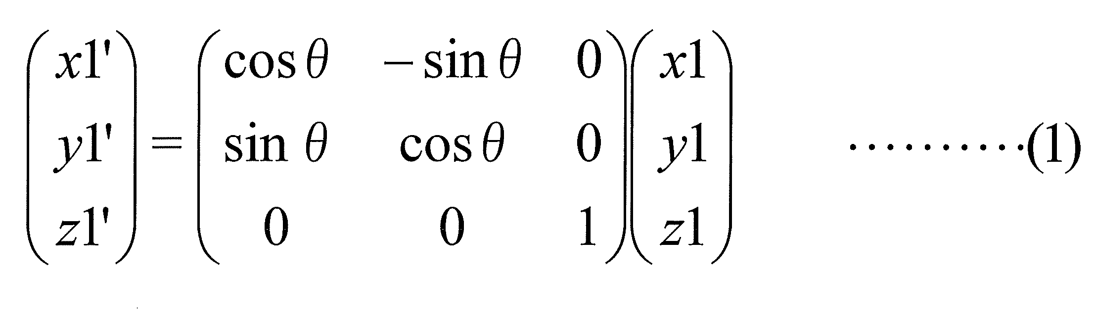
第2の発明は、第1の発明であって、テスト画像は、表示画面に表示されている状態において、画像上の縦方向に延びる縦基準線を含む画像である。
第2の発明は、第1の発明であって、テスト画像は、表示画面に表示されている状態において、画像上の縦方向に延びる縦基準線を含む画像である。
投影画像調整部は、制御信号に従い歪み低減量を決定し、投影面に投影された投影画像の縦基準線を含む平面であって、投影面と垂直な平面内に含まれる点から投影面を見たときに、歪み低減量に相当する分だけ、縦基準線上の1つの点である第1直交点を通り、縦基準線と直交する方向の投影画像の長さである第1距離と、縦基準線上の第1直交点以外の点である第2直交点を通り、縦基準線と直交する方向の投影画像の長さである第2距離との差が小さくなるように(縦基準線と直交する方向に発生している幾何的な歪みが低減されるように(例えば、縦基準線と直交する投影画像の一方の辺の長さと、縦基準線と直交する投影画像の他方の辺の長さとの差が小さくなるように))、回転処理後のテスト画像に対して画像変換処理である台形補正処理を実行する。
この投影システムでは、表示したときの上部が分かるテスト画像を左眼視点と右眼視点とを結ぶ直線と平行な平面を投影面(例えば、水平天井平面等の水平投影面)に投影し、例えば、ユーザーがコントローラにより、(1)投影面内で投影画像を回転させる処理を実行させた後、(2)投影面に投影されている画像の台形補正処理を実行させることで、投影面に投影されている画像の幾何的な歪みをなくす(低減させる)ことができる。
したがって、この投影システムでは、撮影機能を有する機器を用いることなく、左眼視点と右眼視点とを結ぶ直線と平行な平面を投影面(例えば、水平天井平面等の水平投影面)に投影された画像の幾何的な歪みを、容易かつ適切に、なくす(低減させる)ことができる。
なお、「縦基準線と直交する方向に発生している幾何的な歪みが低減される」とは、例えば、投影画像の上方(画像を表示させたときの垂直方向の上方)において、縦基準線と直交する方向の投影画像の長さ(投影画像の幅)と、投影画像の下方(画像を表示させたときの垂直方向の下方)において、縦基準線と直交する方向の投影画像の長さ(投影画像の幅)との差が小さくなる、という概念を含む。
第3の発明は、第2の発明であって、投影画像調整部は、回転処理および台形補正処理の少なくとも一方の処理が実行されたテスト画像を投影面に投影したときの画像の投影状態を調整するための微調整部を備える。
この投影システムでは、微調整部により、上記調整処理を実行するので、例えば、3次元形状測定処理の誤差を修正し、さらに精度の高い画像投影処理(画像の幾何的な歪みの低減処理)を実行することができる。
第4の発明は、第2または第3の発明であって、テスト画像は、表示画面に表示されている状態において、画像上の上部を判別することができるパターンを含む画像である。
これにより、上部を容易に判別することができるテスト画像を用いて、投影システムでの処理を実行することができる。
第5の発明は、第2から第4のいずれかの発明であって、テスト画像は、複数の正方形の格子パターンからなる格子状パターンを含む画像である。
この投影システムでは、このテスト画像(正方形の格子からなる格子状画像)を投影し、投影されたテスト画像の幾何学的な歪みがなくなるように、例えば、コントローラにより、調整処理(画像の幾何的な歪みを低減させるための調整処理)を実行させることができる。このため、この投影システムでは、このテスト画像を用いることで、感覚的に分かりやすい処理により、容易に調整処理(画像の幾何的な歪みを低減させるための調整処理)を実行させることができる。
第6の発明は、第5の発明であって、テスト画像は、第1の模様を有する第1格子パターンと、第2の模様を有する第2格子パターンとが、幾何学的な歪みがない状態において、テスト画像上の第1方向、および、テスト画像上において第1方向と直交する第2方向において、交互に配置されることで形成される格子状パターンを含む画像である。
この投影システムでは、このテスト画像を投影し、投影されたテスト画像の幾何学的な歪みがなくなるように、例えば、コントローラにより、調整処理(画像の幾何的な歪みを低減させるための調整処理)を実行させることができる。このため、この投影システムでは、このテスト画像を用いることで、感覚的に分かりやすい処理により、容易に調整処理(画像の幾何的な歪みを低減させるための調整処理)を実行させることができる。
第7の発明は、第1から第5のいずれかの発明である投影システムに用いられるプロジェクター装置であって、投影部と、投影画像調整部とを備える。
これにより、第1から第6のいずれかの発明である投影システムに用いられるプロジェクター装置を実現することができる。
第8の発明は、左眼視点と右眼視点とを結ぶ直線と平行な平面を投影面とし、ユーザーの視点から見たときに幾何学的な画像歪みが低減された状態となるように画像を投影する投影方法をコンピュータに実行させるためのプログラムである。
投影方法は、投影ステップと、3次元形状測定ステップと、ユーザーの操作に基づく制御信号を生成するステップと、投影画像調整ステップと、を備える。
投影ステップは、投影面にテスト画像を投影する。
3次元形状測定ステップは、投影面の3次元形状を測定する。
(1)投影画像調整ステップは、3次元形状測定ステップにより計測された3次元形状データに基づいて、投影ステップにおける投影軸と投影面との交点である投影中心点を通り、投影面の法線上の点である第1点から見たときに、幾何学的な画像歪みが低減された状態とするように、テスト画像に対して画像変換処理である補正処理を実行する。
(2)投影画像調整ステップは、制御信号に従い回転角度を決定し、第1点から投影面を見たときに、補正処理後のテスト画像の投影ステップによる投影面への投影画像が投影中心点を中心として、制御信号に従い決定した回転角度だけ回転した画像となるように、補正処理後のテスト画像に対して画像変換処理である回転処理を実行する。
これにより、第1の発明と同様の効果を奏する投影方法をコンピュータに実行させるためのプログラムを実現することができる。
第9の発明は、第8の発明であって、テスト画像は、表示画面に表示されている状態において、画像上の縦方向に延びる縦基準線を含む画像である。
投影画像調整ステップは、制御信号に従い歪み低減量を決定し、投影面に投影された投影画像の縦基準線を含む平面であって、投影面と垂直な平面内に含まれる点から投影面を見たときに、制御信号に従い決定した歪み低減量に相当する分だけ、縦基準線と直交する方向に発生している幾何的な歪みが低減されるように、回転処理後の前記テスト画像に対して画像変換処理である台形補正処理を実行する。
これにより、第2の発明と同様の効果を奏する投影方法をコンピュータに実行させるためのプログラムを実現することができる。
第10の発明は、左眼視点と右眼視点とを含む平面に平行な平面であって、右眼角膜および左眼角膜の共通の接平面である当該平面に対して、傾斜した平面を投影面とし、ユーザーの視点から見たときに幾何学的な画像歪みが低減された状態となるように画像を投影する投影システムであって、投影部と、3次元形状測定部と、コントローラと、投影画像調整部と、を備える。
投影部は、投影面に画像を投影する投影部であって、画像の垂直方向を規定する縦基準線を有する第1テスト画像を投影するとともに、画像の水平方向を規定する横基準線を有する第2テスト画像を投影する。
3次元形状測定部は、投影面の3次元形状を測定する。
コントローラは、ユーザーの操作に基づく制御信号を生成する。
投影画像調整部は、以下の処理を実行する。
(1A)投影画像調整部は、3次元形状測定部により計測された3次元形状データに基づいて、投影部の投影軸と投影面との交点である投影中心点を通り、投影面の法線上の点である第1点から見たときに、幾何学的な画像歪みが低減された状態とするように、第1テスト画像に対して画像変換処理である補正処理を実行する。
(2A)投影画像調整部は、制御信号に従い第1回転角度を決定し、第1点から投影面を見たときに、補正処理後の第1テスト画像の投影部による投影面への投影画像が投影中心点を中心として、第1回転角度だけ回転した画像となるように、補正処理後の第1テスト画像に対して画像変換処理である第1回転処理を実行する。
(1B)投影画像調整部は、3次元形状測定部により計測された3次元形状データに基づいて、投影部の投影軸と投影面との交点である投影中心点を通り、投影面の法線上の点である第1点から見たときに、幾何学的な画像歪みが低減された状態とするように、第2テスト画像に対して画像変換処理である補正処理を実行する。
(2B)投影画像調整部は、制御信号に従い第2回転角度を決定し、第1点から投影面を見たときに、補正処理後の第2テスト画像の投影部による投影面への投影画像が投影中心点を中心として、第2回転角度だけ回転した画像となるように、補正処理後の第2テスト画像に対して画像変換処理である第2回転処理を実行する。
(3)投影画像調整部は、第1回転処理後の第1テスト画像の投影面上の縦基準線を含む直線である第1直線と、第2回転処理後の第2テスト画像の投影面上の縦基準線を含む直線である第2直線とに基づいて、第1直線と第2直線とが直交して見える視点候補点を決定し、決定した視点候補点から見たときに幾何学的な画像歪みが低減された状態とするように、投影面に投影される画像を変換する視点特定処理を実行する。
この投影システムでは、上記のようにして視点特定処理が実行され、ユーザーの視点から見たときに幾何的な歪みのない画像(幾何的な歪みの低減された画像)を、例えば、傾斜天井平面に投影することができる。
したがって、この投影システムでは、撮影機能を有する機器を用いることなく、傾斜投影面(例えば、傾斜天井)に投影された画像の幾何的な歪みを、容易かつ適切に、なくす(低減させる)ことができる。
第11の発明は、第10の発明であって、投影画像調整部は、以下の処理を実行する。
投影画像調整部は、投影部の光軸をz軸とし、投影部の光軸を法線とする平面をxy平面とするようにx軸およびy軸を設定したxyz座標空間において、
第1回転処理後の第1テスト画像の投影面上の縦基準線を含む直線である第1直線上の点を点Paとし、点Paの座標を(ax,ay,az)とし、
第2回転処理後の第2テスト画像の投影面上の横基準線を含む直線である第2直線上の点を点Pbとし、点Pbの座標を(bx,by,bz)とし、
第1直線と第2直線との交点を点Pcとして算出し、算出した点Pcの座標を(cx,cy,cz)としたとき、
A=-ax×by+ay×bx
B=-ax×bz+az×bx
C=-az×by+ay×bz
に相当する処理を実行し、係数A、B、Cを取得する。
第1回転処理後の第1テスト画像の投影面上の縦基準線を含む直線である第1直線上の点を点Paとし、点Paの座標を(ax,ay,az)とし、
第2回転処理後の第2テスト画像の投影面上の横基準線を含む直線である第2直線上の点を点Pbとし、点Pbの座標を(bx,by,bz)とし、
第1直線と第2直線との交点を点Pcとして算出し、算出した点Pcの座標を(cx,cy,cz)としたとき、
A=-ax×by+ay×bx
B=-ax×bz+az×bx
C=-az×by+ay×bz
に相当する処理を実行し、係数A、B、Cを取得する。
投影画像調整部は、
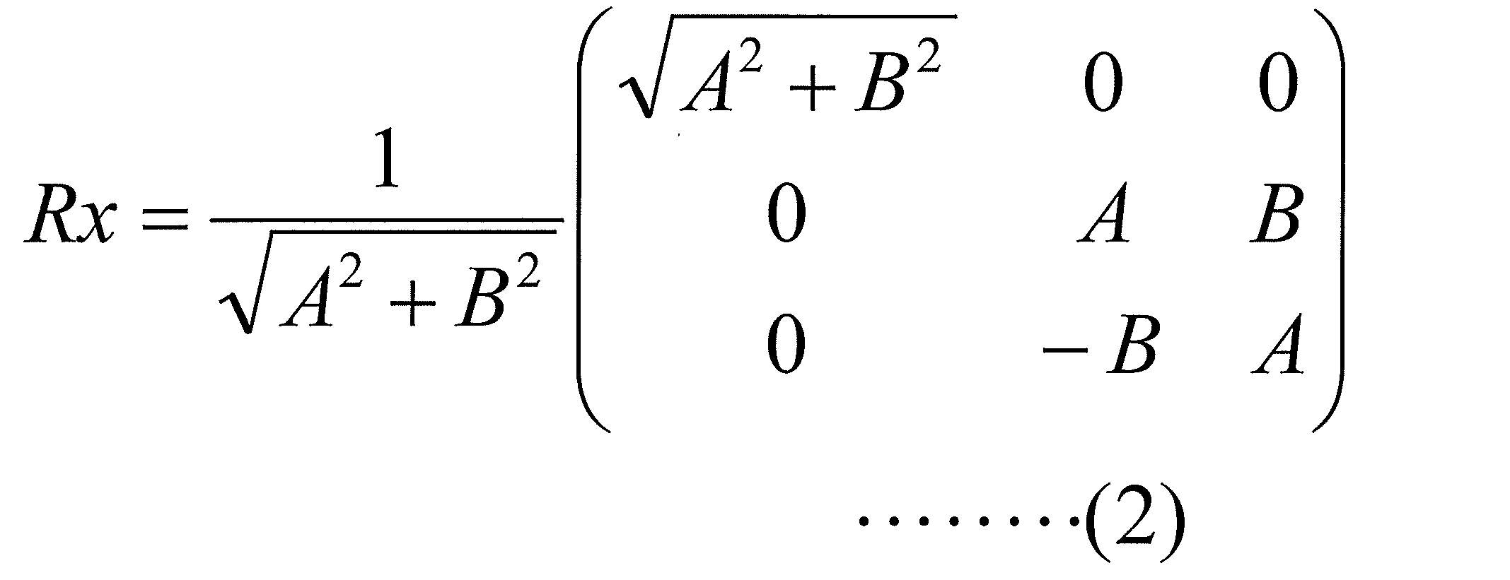

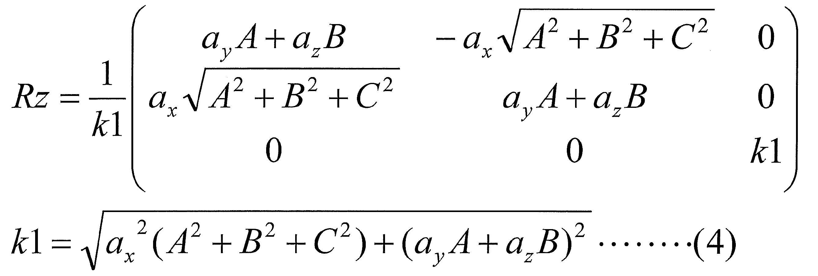
により、回転行列Rx,Ry、Rzを取得する。
投影画像調整部は、回転行列Rx,Ry、Rzの合成行列をR
R=Rz・Ry・Rx
に相当する処理を実行することで取得し、上記回転行列の逆行列をR-1として取得する。
R=Rz・Ry・Rx
に相当する処理を実行することで取得し、上記回転行列の逆行列をR-1として取得する。
投影画像調整部は、点Pbの座標(bx,by,bz)に対して、合成行列により変換した点を点Pb’として取得し、点Pb’の座標を(bx’,by’,bz’)として取得し、
コントローラからの制御信号に基づいて、角度θを決定する。
コントローラからの制御信号に基づいて、角度θを決定する。
投影画像調整部は、係数A’を
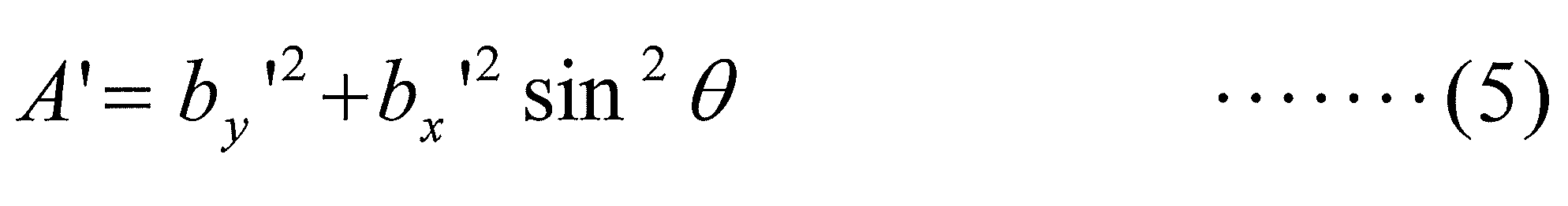
により取得し、
視点候補点の座標(x,y,z)を、
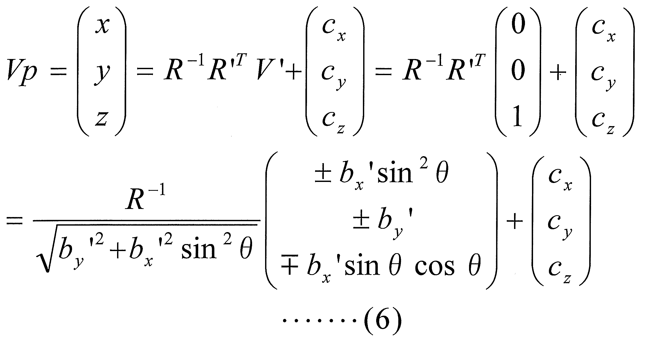
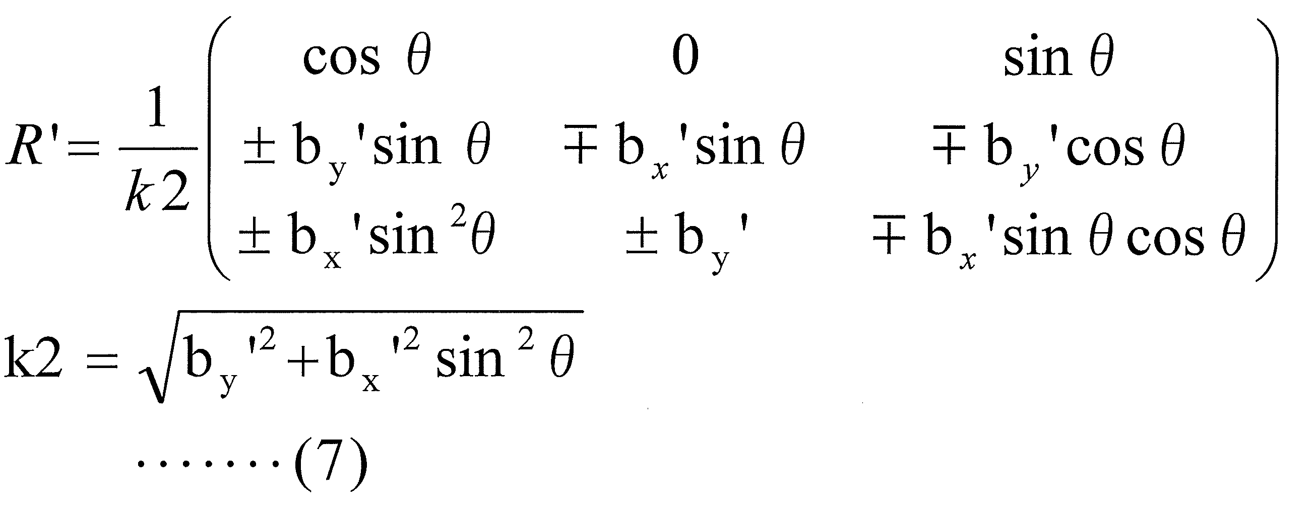
V’=(0,0,1)
により算出する。
視点候補点の座標(x,y,z)を、
により算出する。
この投影システムでは、上記のようにして視点特定処理が実行され、ユーザーの視点から見たときに幾何的な歪みのない画像(幾何的な歪みの低減された画像)を、例えば、傾斜天井平面に投影することができる。
したがって、この投影システムでは、撮影機能を有する機器を用いることなく、傾斜投影面(例えば、傾斜天井)に投影された画像の幾何的な歪みを、容易かつ適切に、なくす(低減させる)ことができる。
第12の発明は、第10または第11の発明であって、第1テスト画像は、表示画面に表示されている状態において、第1テスト画像の中心点を通る縦基準線を含む。
これにより、この投影システムでは、投影面上の第1テスト画像の縦基準線を含む第1直線を特定することが容易になる。
第13の発明は、第10または第11の発明であって、第2テスト画像は、表示画面に表示されている状態において、第2テスト画像の中心点を通る横基準線を含む。
これにより、この投影システムでは、投影面上の第2テスト画像の横基準線を含む第1直線を特定することが容易になる。
第14の発明は、第10から第13のいずれかの発明であって、第1テスト画像は、表示画面に表示されている状態において、画像上の上部を判別することができるパターンを含む画像である。
これにより、この投影システムでは、投影面上の投影画像の上下を容易に特定することができる。
第15の発明は、第10から第14のいずれかの発明であって、投影部は、視点特定処理が実行される場合、複数の正方形の格子パターンからなる格子状パターンを含む第3テスト画像を投影する。
これにより、この投影システムでは、格子状パターンの歪度合いを容易に把握し、投影されている画像の歪度合いを容易に認識することができる。
第16の発明は、第15の発明であって、第3テスト画像は、第1の模様を有する第1格子パターンと、第2の模様を有する第2格子パターンとが、幾何学的な歪みがない状態において、テスト画像上の第1方向、および、テスト画像上において第1方向と直交する第2方向において、交互に配置されることで形成される格子状パターンを含む画像である。
これにより、この投影システムでは、格子状パターンの歪度合いを容易に把握し、投影されている画像の歪度合いを容易に認識することができる。
第17の発明は、第10から第16のいずれかの発明である投影システムに用いられるプロジェクター装置であって、投影部と、投影画像調整部とを備える。
これにより、第1から第7のいずれかの発明である投影システムに用いられるプロジェクター装置を実現することができる。
第18の発明は、ユーザーの操作に基づく制御信号を生成するコントローラを用いて実行される投影方法であって、左眼視点と右眼視点とを含む平面に平行な平面であって、右眼角膜および左眼角膜の共通の接平面である当該平面に対して、傾斜した平面を投影面とし、ユーザーの視点から見たときに幾何学的な画像歪みが低減された状態となるように画像を投影する投影方法をコンピュータで実行するためのプログラムである。
第18の発明は、ユーザーの操作に基づく制御信号を生成するコントローラを用いて実行される投影方法であって、左眼視点と右眼視点とを含む平面に平行な平面であって、右眼角膜および左眼角膜の共通の接平面である当該平面に対して、傾斜した平面を投影面とし、ユーザーの視点から見たときに幾何学的な画像歪みが低減された状態となるように画像を投影する投影方法をコンピュータで実行するためのプログラムである。
投影方法は、投影ステップと、3次元形状測定ステップと、コントローラと、投影画像調整ステップと、を備える。
投影ステップは、投影面に画像を投影する投影ステップであって、画像の垂直方向を規定する縦基準線を有する第1テスト画像を投影するとともに、画像の水平方向を規定する横基準線を有する第2テスト画像を投影する。
3次元形状測定ステップは、投影面の3次元形状を測定する。
投影画像調整ステップは、以下の処理を実行する。
(1A)投影画像調整ステップは、3次元形状測定ステップにより計測された3次元形状データに基づいて、投影ステップで画像を投影するための投影軸と投影面との交点である投影中心点を通り、投影面の法線上の点である第1点から見たときに、幾何学的な画像歪みが低減された状態とするように、第1テスト画像に対して画像変換処理である補正処理を実行する。
(2A)投影画像調整ステップは、制御信号に従い第1回転角度を決定し、第1点から投影面を見たときに、補正処理後の第1テスト画像の投影ステップによる投影面への投影画像が投影中心点を中心として、第1回転角度だけ回転した画像となるように、補正処理後の第1テスト画像に対して画像変換処理である第1回転処理を実行する。
(1B)投影画像調整ステップは、3次元形状測定ステップにより計測された3次元形状データに基づいて、投影ステップで画像を投影するための投影軸と投影面との交点である投影中心点を通り、投影面の法線上の点である第1点から見たときに、幾何学的な画像歪みが低減された状態とするように、第2テスト画像に対して画像変換処理である補正処理を実行する。
(2B)投影画像調整ステップは、制御信号に従い第2回転角度を決定し、第1点から投影面を見たときに、補正処理後の第2テスト画像の投影ステップによる投影面への投影画像が投影中心点を中心として、第2回転角度だけ回転した画像となるように、補正処理後の第2テスト画像に対して画像変換処理である第2回転処理を実行する。
(3)投影画像調整ステップは、第1回転処理後の第1テスト画像の投影面上の縦基準線を含む直線である第1直線と、第2回転処理後の第2テスト画像の投影面上の縦基準線を含む直線である第2直線とに基づいて、第1直線と第2直線とが直交して見える視点候補点を決定し、決定した視点候補点から見たときに幾何学的な画像歪みが低減された状態とするように、投影面に投影される画像を変換する視点特定処理を実行する。
これにより、第10の発明と同様の効果を奏する投影方法をコンピュータに実行させるためのプログラムを実現することができる。
本発明によれば、撮影機能を有する機器を用いることなく、水平投影面(例えば、水平天井)やユーザーの両眼を結ぶ直線と平行な平面(例えば、前方傾斜平面や後方傾斜平面)に投影された画像の幾何的な歪みを、容易かつ適切に、低減させる投影システム、プロジェクター装置、および、プログラムを実現することができる。
また、本発明によれば、撮影機能を有する機器を用いることなく、傾斜平面(例えば、傾斜天井)に投影された画像の幾何的な歪みを、容易かつ適切に、低減させる投影システム、プロジェクター装置、および、プログラムを実現することができる。
[第1実施形態]
第1実施形態について、図面を参照しながら、以下、説明する。
第1実施形態について、図面を参照しながら、以下、説明する。
<1.1:投影システムの構成>
図1は、第1実施形態に係る投影システム1000の概略構成図である。
図1は、第1実施形態に係る投影システム1000の概略構成図である。
図2は、第1実施形態に係る投影システム1000のプロジェクター装置100の投影画像調整部1の概略構成図である。
投影システム1000は、図1に示すように、プロジェクター装置100と、コントローラ200とを備える。
プロジェクター装置100は、図1に示すように、投影画像調整部1と、テスト画像記憶部2と、投影部3と、3次元形状測定部4と、3次元形状データ記憶部5と、第1インターフェース6とを備える。
投影画像調整部1は、図2に示すように、第1セレクタ11と、補正部12と、切替器13と、回転処理部14と、第2セレクタ15と、台形補正処理部16と、第3セレクタ17と、第4セレクタ18と、を備える。
第1セレクタ11は、プロジェクター装置100に入力される画像Din(画像信号Din)と、テスト画像記憶部2から出力されるテスト画像Img1と、選択信号sel1と、を入力する。第1セレクタ11は、選択信号sel1に従い、画像Dinおよびテスト画像Img1のいずれか一方を選択し、選択した画像(画像信号)を画像D1(画像信号D1)として補正部12に出力する。なお、選択信号sel1は、プロジェクター装置100の各機能部を制御する制御部(不図示)により生成される制御信号である。
補正部12は、第1セレクタ11から出力される画像D1と、3次元形状データ記憶部5から出力される3次元形状データ3D_dataと、投影部3の投影点についての情報P_prjと、を入力する。補正部12は、3次元形状データ3D_dataと、投影点についての情報P_prjとに基づいて、画像D1に対して補正処理を実行する。そして、補正部12は、補正処理後の画像を画像D2(画像信号D2)として、第2セレクタ15と、回転処理部14とに出力する。
切替器13は、第1インターフェース6から出力される信号Sig1と、選択信号sel2とを入力する。切替器13は、選択信号sel2に従い、信号Sig1を、回転処理部14または台形補正処理部16に出力する。なお、選択信号sel2は、プロジェクター装置100の各機能部を制御する制御部により生成される制御信号である。
回転処理部14は、補正部12から出力される画像D2と、3次元形状データ記憶部5から出力される3次元形状データ3D_dataと、投影部3の投影点についての情報P_prjと、切替器13から出力される信号Sig1とを入力する。回転処理部14は、信号Sig1が入力されている場合、3次元形状データ3D_dataと、投影部3の投影点についての情報P_prjとに基づいて、画像D2に対して回転処理を実行する。そして、回転処理部14は、処理後の画像を、画像D21(画像信号D21)として、第2セレクタ15に出力する。
第2セレクタ15は、補正部12から出力される画像D2と、回転処理部14から出力される画像D21と、選択信号sel3とを入力する。第2セレクタ15は、選択信号sel3に従い、画像D2および画像D21のいずれか一方を選択し、選択した画像を、画像D3(画像信号D3)として、台形補正処理部16と、第3セレクタ17とに出力する。なお、選択信号sel3は、プロジェクター装置100の各機能部を制御する制御部により生成される制御信号である。
台形補正処理部16は、第2セレクタ15から出力される画像D3と、3次元形状データ記憶部5から出力される3次元形状データ3D_dataと、投影部3の投影点についての情報P_prjと、切替器13から出力される信号Sig1とを入力する。台形補正処理部16は、信号Sig1が入力されている場合、3次元形状データ3D_dataと、投影部3の投影点についての情報P_prjとに基づいて、画像D3に対して台形補正処理を実行する。そして、台形補正処理部16は、処理後の画像を、画像D31(画像信号D31)として、第3セレクタ17に出力する。
第3セレクタ17は、第2セレクタ15から出力される画像D3と、台形補正処理部16から出力される画像D31と、選択信号sel4とを入力する。第3セレクタ17は、選択信号sel4に従い、画像D3および画像D31のいずれか一方を選択し、選択した画像を、画像D4(画像信号D4)として、第4セレクタ18に出力する。なお、選択信号sel4は、プロジェクター装置100の各機能部を制御する制御部により生成される制御信号である。
第4セレクタ18は、第3セレクタ17から出力される画像D4と、テスト画像記憶部2から出力されるテスト画像Img0と、選択信号sel5とを入力する。第4セレクタ18は、選択信号sel5に従い、画像D4およびテスト画像Img0のいずれか一方を選択し、選択した画像を、画像Dout(画像信号Dout)として、投影部3に出力する。なお、選択信号sel5は、プロジェクター装置100の各機能部を制御する制御部により生成される制御信号である。
テスト画像記憶部2は、テスト画像を記憶しており、投影画像調整部1から要求に従い、所定のタイミングで、テスト画像を、投影画像調整部1に出力する。
投影部3は、画像を投影するための光学系を有している。投影部3は、投影画像調整部1の第4セレクタ18から出力される画像Dout(画像信号Dout)を入力し、入力した画像Dout(画像信号Dout)を、3次元空間の投影対象に投影する。
3次元形状測定部4は、3次元空間の投影対象の3次元計測データを取得し、取得した投影対象の3次元計測データを3次元形状データ記憶部5に出力する。3次元形状測定部4は、例えば、カメラを有しており、投影部3から投影される3次元形状測定用のテスト画像を撮像し、3次元形状測定用のテスト画像の撮像画像に基づいて、投影対象の3次元計測データを取得する。
3次元形状測定部4は、例えば、(1)投影面の法線を求め、投影部3と投影面との位置関係を明確にする、あるいは、(2)投影部3の投影軸(投影部3の光学系の光軸)と投影面との角度を求め、投影部3と投影面との位置関係を明確にすることで、投影対象(投影面)の3次元計測データを取得する。
また、3次元形状測定部4は、TOF(Time Of Flight)方式(例えば、TOF方式の位相差法)により距離画像を取得することで、投影対象の3次元計測データを取得するものであってもよい。この場合、3次元形状測定部4は、例えば、赤外線を照射する光源と、赤外線用のイメージセンサーとを有しており、光源から照射した赤外線の反射光を、イメージセンサーで受光し、照射した赤外線が投影対象から反射されて戻ってくるまでの時間を測定することで、距離画像を取得する。そして、3次元形状測定部4は、取得した距離画像により、投影対象の3次元計測データを取得する。
また、3次元形状測定部4は、レーザー光源とレーザー用のセンサーを有し、レーザー光の飛行時間から、投影対象の距離を測定することで、投影対象の3次元計測データを取得するものであってもよい。この場合、3次元形状測定部4は、レーザー光を投影対象に照射方向を順次変更しながら(投影対象をレーザー光でスキャンしながら)照射し、レーザー光が投影対象に反射し、戻ってくるまでの時間を測定することで、投影対象の距離を測定し、投影対象の3次元計測データを取得する。
3次元形状データ記憶部5は、3次元形状測定部4により取得された投影対象の3次元計測データを入力とし、入力された投影対象の3次元計測データを記憶する。3次元形状データ記憶部5は、補正部12、回転処理部14、台形補正処理部16からの要求に従い、3次元計測データを、補正部12、回転処理部14、台形補正処理部16に出力する。
第1インターフェース6は、プロジェクター装置100と、コントローラ200とのインターフェースである。第1インターフェース6を介して、例えば、コントローラ200から出力される信号を、プロジェクター装置100に入力することができる。
コントローラ200は、図1に示すように、第2インターフェース21と、制御部22と、ユーザーインターフェース23とを備える。
第2インターフェース21は、コントローラ200と、プロジェクター装置100とのインターフェースである。
制御部22は、コントローラ200の各機能部を制御する制御部である。
ユーザーインターフェース23は、ユーザーの操作に応じた信号を発生させる。ユーザーインターフェース23は、例えば、コントローラに設けられた所定のボタンを、ユーザーが押下した場合、当該ボタンが押下されたことを示す信号を発生させる。
<1.2:投影システムの動作>
以上のように構成された投影システム1000の動作について、以下、説明する。
以上のように構成された投影システム1000の動作について、以下、説明する。
以下では、投影システム1000で実行される処理として、(1)3次元形状測定処理、(2)補正処理、(3)回転処理、および、(4)台形補正処理に分けて説明する。
なお、説明便宜のため、投影対象を図3に示す3次元空間として、投影システム1000の動作について説明する。
図3は、3次元空間を模式的に示した図であり、投影対象である天井CL(水平天井CL)と、プロジェクター装置100と、床FL上のユーザーUsrとを示している。図3に示す3次元空間において、天井CL(水平天井CL)は、平面であり、平面である床FLと平行である。また、図3において、プロジェクター装置100の投影部3の投影点を点P_prjとして示しており、プロジェクター装置100の3次元形状測定部4の測定点を点P_msrとして示している。また、図3において、投影部3の光学系の光軸(投影軸)Ax1と、水平天井(平面)CLとの交点を点Pcとし、ユーザーの視点位置(ユーザーの両眼の中心点)を点Vpとして示している。また、図3において、点Pcを通り、水平天井平面CLの法線Nm1と、床平面FLと平行な平面であって、点Vpを含む平面との交点を点P1として示している。
また、図3において、ユーザーUsrの左眼の位置と点Pcとの距離と、ユーザーUsrの右眼の位置と点Pcとの距離とは、等しいものする。
なお、図3において、図3中に示すように、x軸、y軸、z軸をとるものとする。
(1.2.1:3次元形状測定処理)
まず、3次元形状測定処理について、説明する。
まず、3次元形状測定処理について、説明する。
以下では、投影システム1000において、3次元形状測定部4は、カメラを有しており、投影部3から投影される3次元形状測定用のテスト画像を撮像し、3次元形状測定用のテスト画像の撮像画像に基づいて、投影対象の3次元計測データを取得する場合について、説明する。
テスト画像記憶部2から、3次元形状測定用のテスト画像Img0が、投影画像調整部1の第4セレクタ18に出力される。制御部は、第4セレクタ18の、図2に示す端子0を選択する選択信号sel5を生成し、第4セレクタ18に出力する。これにより、第4セレクタ18から、3次元形状測定用のテスト画像Img0が、画像信号Doutとして、投影部3に出力される。
投影部3は、3次元形状測定用のテスト画像Img0を、(A)投影軸(投影部3の光学系の光軸)を、図3に示す軸Ax1とし、(B)画角を図3に示す角度αとし、(C)投影点を、図3に示す点P_prjとして、投影対象である水平天井平面CLに対して、投影する。
3次元形状測定部4は、撮像点が点P_msrである、3次元形状測定用のカメラにより、投影部3により投影されている3次元形状測定用のテスト画像Img0を撮像する。そして、3次元形状測定部4は、撮像した画像を、3次元形状測定用のテスト画像Img0と比較することで、投影対象の3次元計測データを取得する。
投影システム1000において、投影点P_prjの3次元空間の座標が既知であり、3次元形状測定部4の撮像点P_msrの3次元空間の座標が既知であり、投影する3次元形状測定用のテスト画像Img0が既知であるので、撮像点P_msrで撮像した画像から、投影対象の3次元空間の座標を算出することができる。つまり、3次元形状測定用のテスト画像Img0の各画素が、撮像点P_msrで撮像した画像のどの画素に対応するか調べることで、各画素に相当する3次元空間位置(各画素に相当する光が反射した3次元空間位置)を特定することができる。したがって、各画素に対応する3次元空間位置を特定することで、投影対象の3次元空間の座標を算出することができる。
なお、3次元形状測定用のテスト画像Img0を、例えば、所定の周期の正弦波信号により形成される画像としてもよい。この場合、例えば、正弦波信号の周期や位相を所定のタイミングで変更した複数の画像を、投影部3から投影対象に投影し、投影された複数の画像により、3次元形状測定部4が、投影対象の3次元形状データを取得するようにしてもよい。
上記処理により、3次元形状測定部4が取得した投影対象の3次元形状データは、3次元形状測定部4から、3次元形状データ記憶部5に出力され、3次元形状データ記憶部5に記憶される。
(1.2.2:補正処理)
次に、補正処理について、説明する。
次に、補正処理について、説明する。
テスト画像記憶部2から、テスト画像Img1が、第1セレクタ11に出力される。そして、制御部は、第1セレクタ11の、図2に示す端子0を選択する選択信号sel1を生成し、第1セレクタ11に出力する。これにより、第1セレクタ11から、テスト画像Img1が、画像信号D1として、補正部12に出力される。
図4に、テスト画像Img1の一例を示す。図4に示すように、テスト画像Img1は、白地の正方形のパターンである第1格子パターンと、黒地の正方形のパターンである第2格子パターンとが、画像上の水平方向、および、画像上の垂直方向において、交互に配置されることで形成される格子状パターンを有している。また、テスト画像Img1は、図4に示すように、画像の中央に中心線L1vを有し、画像Img1の中心点に円C1を有し、画像Img1の上部に水平方向(横方向)に引かれた線L1hを有するパターンの画像である。
図4に示すテスト画像Img1は、線L1vと線L1hとの交点が存在する部分が画像の上部である。投影システム1000では、テスト画像Img1の画像の上側をユーザーに認識させる必要があるため、投影システム1000に用いるテスト画像は、図4に示すテスト画像Img1のように、画像の上部を認識しやすい画像とすることが好ましい。なお、図4に示すテスト画像Img1は、一例であり、画像の上部を認識できる画像であれば、他の画像であってもよい。
例えば、テスト画像は、白地の正方形のパターンである第1格子パターンと、黒地の正方形のパターンである第2格子パターンとが、画像上の水平方向、および、画像上の垂直方向において、交互に配置されることで形成される格子状パターンを、画像領域全面に有しており、画像の上部を示す特定のパターンが、テストパターン画像の所定の場所に重畳された画像であってもよい。
説明便宜のため、以下では、テスト画像として、図4に示すテスト画像Img1を用いる場合について説明する。
補正部12は、3次元形状データ記憶部5から3次元形状データ3D_dataを読み出し、投影対象である水平天井平面CLの3次元座標データを取得する。そして、補正部12は、点P1、すなわち、投影軸Ax1と天井平面CLとの交点Pcの真下の点P1から見た場合に、幾何的な歪みのない状態の画像となるように、画像D1に対して補正処理を行う。そして、補正部12は、補正処理後の画像を画像D2として第2セレクタ15に出力する。
制御部は、第2セレクタ15の、図2に示す端子0を選択する選択信号sel3を生成し、第2セレクタ15に出力する。これにより、第2セレクタ15から、画像D2が、画像D3として、第3セレクタ17に出力される。
制御部は、第3セレクタ17の、図2に示す端子0を選択する選択信号sel4を生成し、第3セレクタ17に出力する。これにより、第3セレクタ17から、画像D3が、画像D4として、第4セレクタ18に出力される。
制御部は、第4セレクタ18の、図2に示す端子1を選択する選択信号sel5を生成し、第4セレクタ18に出力する。これにより、第4セレクタ18から、画像D4が、画像Doutとして、投影部3に出力される。
投影部3は、第4セレクタ18からの画像Doutを、図3に示す投影軸Ax1により、水平天井平面CLに投影する。なお、この状態を「状態1」とする。
図5は、状態1における水平天井平面CLと、床FLと、ユーザーUsrの視点Vpと、投影部3の光学系の光軸(投影軸)Ax1と水平天井(平面)CLとの交点Pcと、点Pcを通り、水平天井平面CLの法線Nm1と、床平面FLと平行な平面であって、点Vpを含む平面との交点P1とを、x軸正方向からx軸負方向に向かって見た図(yz平面図)である。なお、図5において、L1は、床FLと平行な平面であって視点Vpを含む平面を示している。
また、図3において、状態1における視点Vpから見たテスト画像Img1を、画像Img1(Vp)として示している。さらに、図3において、点P1(点Pcの真下の点)から見たテスト画像Img1を、画像Img1(P1)として示している。
図3から分かるように、状態1において、ユーザーUsrの視点Vpから見た画像Img1(Vp)は、幾何的な歪みが発生しているが、点P1(点Pcの真下の点)から見たテスト画像Img1(P1)は、幾何的な歪みが発生していない。
投影システム1000において、上記のようにして補正処理が実行された後、回転処理が実行される。
(1.2.3:回転処理)
次に、回転処理について、説明する。
次に、回転処理について、説明する。
図6は、状態1における3次元空間を模式的に示した図であり、回転処理を説明するための図である。
図6に示した状態1において、ユーザーは、コントローラ200を操作することで、水平天井平面CLに投影されている画像Img1を、点Pcを中心として、図6に矢印Dir1で示す方向に回転させ、画像Img1の中心線L1vが、ユーザーの視点Vpから見て垂直な直線に見えるようにする。つまり、画像Img1の中心線L1vが、点Pc、点P1、および、視点Vpを含む平面内となるように、ユーザーは、コントローラ200を操作し、水平天井平面CLに投影されている画像Img1を、点Pcを中心として、図6に矢印Dir1で示す方向に回転させる。なお、ユーザーは、画像Img1の画像の上部(画像Img1の線L1vと線L1hとが交差している部分)が、ユーザーから見たときに上部となるように、画像Img1を回転させる。
この回転処理について、具体的に説明する。
状態1と同様に、テスト画像記憶部2から、テスト画像Img1が、第1セレクタ11に出力される。そして、制御部は、第1セレクタ11の、図2に示す端子0を選択する選択信号sel1を生成し、第1セレクタ11に出力する。これにより、第1セレクタ11から、テスト画像Img1が、画像信号D1として、補正部12に出力される。
補正部12は、画像D1に対して、状態1で実行した処理と同じ補正処理を実行する。そして、補正部12は、補正処理後の画像を画像D2として回転処理部14に出力する。
ユーザーは、コントローラ200を操作し、プロジェクター装置100に回転処理を実行させる。例えば、コントローラ200は、回転処理を行うためのボタンを2つ有しており、第1ボタン(一方のボタン)を1回押下することで、テスト画像Img1を、図6の方向Dir1の左方向に所定の角度だけ回転させる処理を実行し、第2ボタン(他方のボタン)を1回押下することで、テスト画像Img1が、図6の方向Dir1の右方向に所定の角度だけ回転させる処理を実行することができる。
ここでは、第1ボタンが押下された場合について説明する。
コントローラ200の第1ボタンが1回押下されると、ユーザーインターフェース23は、第1ボタンが1回押下されたこと示す信号を発生させる。コントローラ200の制御部22は、ユーザーインターフェース23が発生させた信号に基づいて、第1ボタンが1回押下されたこと示す信号を、第2インターフェース21を介して、プロジェクター装置100の第1インターフェースに送信する。
なお、コントローラ200は、ユーザーが手に持って操作できるものであり、コントローラ200とプロジェクター装置100とは、例えば、無線通信により、信号の送受信を行う。
例えば、ユーザーは、図6に示す状態において、コントローラ200を手に持って、水平天井平面CLに投影されている画像Img1を見ながら、コントローラ200を操作し、水平天井平面CLに投影されている画像Img1を回転させる。
プロジェクター装置100の第1インターフェース6は、コントローラ200の第2インターフェース21から送信された信号を受信し、受信した信号を信号Sig1として切替器13に出力する。
切替器13は、制御部により生成された選択信号sel2に基づいて、図2に示す端子1を選択し、信号Sig1を回転処理部14に出力する。
回転処理部14は、信号Sig1と、3次元形状データ3D_dataと、投影部3の投影点についての情報P_prjとに基づいて、補正部12から出力される画像D2に対して回転処理を実行する。
具体的には、回転処理部14は、点P1から水平天井平面CLを見たときに、点Pcを中心として、画像Img1が、図6に示す矢印Dir1の左方向に、信号Sig1により決定される所定の角度だけ回転した画像となるように、画像D2に対して変換処理(回転処理)を行う。そして、回転処理部14は、処理後の画像を、画像D21(画像信号D21)として、第2セレクタ15に出力する。
第2セレクタ15は、制御部により生成された選択信号sel3に基づいて、図2に示す端子1を選択し、画像D21を画像D3として、第3セレクタ17に出力する。
第3セレクタ17は、制御部により生成された選択信号sel4に基づいて、図2に示す端子0を選択し、画像D3(=画像D21)を、画像D4として、第4セレクタ18に出力する。
第4セレクタ18は、制御部により生成された選択信号sel5に基づいて、図2に示す端子1を選択し、画像D4(=画像D21)を、画像Doutとして、投影部3に出力する。
投影部3は、第4セレクタ18からの画像Dout(=画像D21)を、図3に示す投影軸Ax1により、水平天井平面CLに投影する。これにより、点P1から水平天井平面CLを見たときに、画像Img1は、点Pcを中心として、所定の角度だけ方向Dir1に回転した画像となる。
上記操作を繰り返すことで、画像Img1の中心線L1vが、ユーザーの視点Vpから見て垂直な直線に見えるようにする。この状態、つまり、画像Img1の中心線L1vが、点Pc、点P1、および、視点Vpを含む平面内となった状態を「状態2」とする。
図7は、状態2における3次元空間を模式的に示した図である。図7では、状態2において、ユーザの視点Vpから見たテスト画像Img1を画像Img1(Vp)として示している。また、図7では、状態2において、点P1から見たテスト画像Img1を画像Img1(P1)として示している。
図7から分かるように、状態2において、ユーザーの視点Vpからテスト画像Img1を見ると台形の画像に見える(画像Img1(Vp1))。
投影システム1000において、上記のようにして回転処理を実行し、投影システム1000の投影状態を状態2の状態にした後、台形補正処理が実行される。
(1.2.4:台形補正処理)
次に、台形補正処理について、説明する。
次に、台形補正処理について、説明する。
図8は、台形補正処理を説明するための図である。図8は、状態2における水平天井平面CLと、床FLと、ユーザーUsrの視点Vpと、投影部3の光学系の光軸(投影軸)Ax1と水平天井(平面)CLとの交点Pcと、点Pcを通り、水平天井平面CLの法線Nm1と、床平面FLと平行な平面であって、点Vpを含む平面との交点P1とを、x軸正方向からx軸負方向に向かって見た図(yz平面図)である。なお、図8において、L1は、床FLと平行な平面であって視点Vpを含む平面を示している。
図9~図13は、台形補正処理を説明するための図である。図9~図13は、図8と同様に、水平天井平面CLと、床FLと、ユーザーUsrの視点Vpと、点Pcと、交点P1とを、x軸正方向からx軸負方向に向かって見た図(yz平面図)である。
図14は、状態3における3次元空間を模式的に示した図であり、台形補正処理を説明するための図である。
図7、図8に示した状態2において、ユーザーは、コントローラ200を操作することで、プロジェクター装置100に、水平天井平面CLに投影されている画像Img1に対する台形補正処理を実行させる。
台形補正処理は、例えば、以下の(1)、(2)の処理により実行される。
(1)図8に示すように、点Pcを通り、かつ、x軸と平行な軸を回転軸として、水平天井平面CLに投影されている画像Img1(状態2の画像Img1(これを画像Img(state2)と表記する))を、図8に示す方向Dir2(時計回り方向)に所定の角度だけ回転させた平面を仮想投影面(例えば、図8に示した仮想投影面SF1)として設定する。
(2)点Pcを通り、上記で設定した仮想投影面の法線上の点(図8、図9に示す点P2)からみたときに、幾何的な歪みのない画像となるように、回転処理後の画像Img1に対して画像変換処理(台形補正処理)を行う。
(1)図8に示すように、点Pcを通り、かつ、x軸と平行な軸を回転軸として、水平天井平面CLに投影されている画像Img1(状態2の画像Img1(これを画像Img(state2)と表記する))を、図8に示す方向Dir2(時計回り方向)に所定の角度だけ回転させた平面を仮想投影面(例えば、図8に示した仮想投影面SF1)として設定する。
(2)点Pcを通り、上記で設定した仮想投影面の法線上の点(図8、図9に示す点P2)からみたときに、幾何的な歪みのない画像となるように、回転処理後の画像Img1に対して画像変換処理(台形補正処理)を行う。
この台形補正処理について、具体的に説明する。
状態1、2と同様に、テスト画像記憶部2から、テスト画像Img1が、第1セレクタ11に出力される。そして、制御部は、第1セレクタ11の、図2に示す端子0を選択する選択信号sel1を生成し、第1セレクタ11に出力する。これにより、第1セレクタ11から、テスト画像Img1が、画像信号D1として、補正部12に出力される。
補正部12は、画像D1に対して、状態1、2で実行した処理と同じ補正処理を実行する。そして、補正部12は、補正処理後の画像を画像D2として回転処理部14に出力する。
回転処理部14は、状態2において実行した処理と同じ回転処理を実行する。そして、回転処理部14は、画像D2に対して回転処理が実行された後の画像D21を第2セレクタ15に出力する。
第2セレクタ15は、制御部により生成された選択信号sel3に基づいて、図2に示す端子1を選択し、画像D21を画像D3として、台形補正処理部16に出力する。
ユーザーは、コントローラ200を操作し、プロジェクター装置100に台形補正処理を実行させる。例えば、コントローラ200は、台形補正処理を行うためのボタンを2つ有しており、当該ボタンを押下することで、例えば、以下の(1)、(2)の処理を、プロジェクター装置100に実行させる。
(1)コントローラ200の第1ボタン(一方のボタン)を1回押下することで、水平天井平面CLを、図9に示す方向Dir2(時計回り方向)に所定の角度だけ回転させた位置に仮想平面を設定し、点Pcを通り、当該仮想平面の法線上の点から見たときに幾何的な歪みがない状態となるように、画像変換処理(台形補正処理)を、プロジェクター装置100に実行させる。
(2)コントローラ200の第2ボタン(他方のボタン)を1回押下することで、水平天井平面CLを、図9に示す方向Dir2と反対の方向(反時計回り方向)に所定の角度だけ回転させた位置に仮想平面を設定し、点Pcを通り、当該仮想平面の法線上の点から見たときに幾何的な歪みがない状態となるように、画像変換処理(台形補正処理)を、プロジェクター装置100に実行させる。
ここでは、第1ボタンが押下された場合について説明する。
コントローラ200の第1ボタンが1回押下されると、ユーザーインターフェース23は、第1ボタンが1回押下されたこと示す信号を発生させる。コントローラ200の制御部22は、ユーザーインターフェース23が発生させた信号に基づいて、第1ボタンが1回押下されたこと示す信号を、第2インターフェース21を介して、プロジェクター装置100の第1インターフェース6に送信する。
なお、コントローラ200は、ユーザーが手に持って操作できるものであり、コントローラ200とプロジェクター装置100とは、例えば、無線通信により、信号の送受信を行う。
例えば、ユーザーは、図7に示す状態において、コントローラ200を手に持って、水平天井平面CLに投影されている画像Img1を見ながら、コントローラ200を操作し、水平天井平面CLに投影されている画像Img1の幾何的な歪みを低減させる処理(台形補正処理)を実行させる。
プロジェクター装置100の第1インターフェース6は、コントローラ200の第2インターフェース21から送信された信号を受信し、受信した信号を信号Sig1として切替器13に出力する。
切替器13は、制御部により生成された選択信号sel2に基づいて、図2に示す端子0を選択し、信号Sig1を台形補正処理部16に出力する。
台形補正処理部16は、信号Sig1と、3次元形状データ3D_dataと、投影部3の投影点についての情報P_prjとに基づいて、第2セレクタ15から出力される画像D3に対して台形補正処理を実行する。
具体的には、台形補正処理部16は、信号Sig1から、コントローラ200の第1ボタン(一方のボタン)を1回押下したときの回転角度θ1を決定する。そして、台形補正処理部16は、水平天井平面CLを、図9に示す方向Dir2(時計回り方向)に回転角度θ1だけ回転させた位置に仮想平面SF1を設定し、点Pcを通り、仮想平面SF1の法線上の点P2から水平天井平面CLを見たときに、水平天井平面CLに投影されている画像の幾何的な歪みがない状態となるように、画像D3に対して、画像変換処理(台形補正処理)を実行する。そして、台形補正処理部16は、台形補正処理後の画像を画像D31として、第3セレクタ17に出力する。
第3セレクタ17は、制御部により生成された選択信号sel4に基づいて、図2に示す端子1を選択し、画像D31を、画像D4として、第4セレクタ18に出力する。
第4セレクタ18は、制御部により生成された選択信号sel5に基づいて、図2に示す端子1を選択し、画像D4(=画像D31)を、画像Doutとして、投影部3に出力する。
投影部3は、第4セレクタ18からの画像Dout(=画像D31)を、図3に示す投影軸Ax1により、水平天井平面CLに投影する。これにより、点P2から水平天井平面CLを見たときに、画像Img1は、幾何的な歪みのない画像として投影される。このときの様子を図10に示す。
図10に示す画像Img_R1_CLは、以下のようにして取得される画像である。つまり、画像Img_R1_CLは、状態2の水平天井平面CLの画像Img(state2)を、点Pcを通り、かつ、x軸と平行な軸を回転軸として、yz平面内で時計回り方向(方向Dir2)に角度θ1だけ回転させた画像(図10の画像Img_R1(仮想平面SF1上の画像Img_R1))を、仮想平面SF1の法線上の点(例えば、点P2)から、水平天井平面CLに投影することで取得される画像である。
また、図10の右上側に、状態2において、点Vpから水平天井平面CLを見たときの画像Img1(state2)を示し、図10の右下側に、上記台形補正処理が実行されたときの点Vpから水平天井平面CLを見たときの画像Img1_R1_CLを示している。
また、図10の左側に、上記台形補正処理が実行されたときの点P2から水平天井平面CLを見たときの画像Img1_R1_CLを示している。
図10の右下側に示した画像Img1_R1_CLは、図10の右上側に示した画像Img1(state2)よりも幾何的な歪み(台形歪み)が低減されていることが分かる。これにより、ユーザーは、第1ボタンをさらに押下することで、図10に示す回転角度θ1をさらに大きな角度とする台形補正処理を実行し、水平天井平面CLに投影されている画像の幾何的な歪みをさらに低減させることができる。
なお、ユーザーは、第1ボタンを押下したときに、水平天井平面CLに投影されている画像の幾何的な歪み(台形歪み)が大きくなることを認識した場合、コントローラ200の他方のボタンである第2ボタンを押下することで、プロジェクター装置100に、水平天井平面CLに投影されている画像の幾何的な歪み(台形歪み)を低減させる台形補正処理を実行させることができる。
ここでは、図10に示すように、コントローラ200の第1ボタンを押下することで、水平天井平面CLに投影されている画像の幾何的な歪み(台形歪み)が低減されることが分かるので、ユーザーは、さらに、第1ボタンを押下し、プロジェクター装置100に台形補正処理を実行させる。
ユーザーがさらに第1ボタンを押下した場合、プロジェクター装置100では、上記と同様の処理が実行される。そして、台形補正処理部16により、図10に示す回転角度θ1をさらに大きな角度とする台形補正処理を実行する。
ここでは、ユーザーがさらに第1ボタンを押下した場合、図11に示すように、回転角度がθ2となり、水平天井平面CLを、点Pcを通り、かつ、x軸と平行な軸を回転軸として、yz平面内で時計回り方向(方向Dir2)に角度θ2だけ回転させた仮想平面SF2の点Pcを通る法線が、ユーザーの視点Vpを通る状態となったものとして説明する。
この場合、台形補正処理部16は、信号Sig1から、コントローラ200の第1ボタン(一方のボタン)がさらに押下したときの回転角度θ2を決定する。そして、台形補正処理部16は、水平天井平面CLを、図11に示す方向Dir2(時計回り方向)に回転角度θ2だけ回転させた位置に仮想平面SF2を設定し、点Pcを通り、仮想平面SF2の法線上の点Vpから水平天井平面CLを見たときに、水平天井平面CLに投影されている画像の幾何的な歪みがない状態となるように、画像D3に対して、画像変換処理(台形補正処理)を実行する。そして、台形補正処理部16は、台形補正処理後の画像を画像D31として、第3セレクタ17に出力する。
このようにして台形補正処理部16により生成された画像D31は、投影部3により、水平天井平面CLに投影される。この状態を「状態3」とする。
これにより、ユーザーの視点Vpから水平天井平面CLを見たときに、画像Img1は、幾何的な歪みのない画像(幾何的な歪みの低減された画像)として投影される。このときの様子を図12に示す。
図12に示す画像Img_R2_CLは、以下のようにして取得される画像である。つまり、画像Img_R2_CLは、状態2の水平天井平面CLの画像Img(state2)を、点Pcを通り、かつ、x軸と平行な軸を回転軸として、yz平面内で時計回り方向(方向Dir2)に角度θ2だけ回転させた画像(図12の画像Img_R2(仮想平面SF2上の画像Img_R2))を、仮想平面SF2の法線上の点(例えば、視点Vp)から、水平天井平面CLに投影することで取得される画像である。
また、図12の右上側に、状態2において、点Vpから水平天井平面CLを見たときの画像Img1(state2)を示し、図12の右下側に、上記台形補正処理が実行されたときの点Vpから水平天井平面CLを見たときの画像Img1_R2_CL、すなわち、状態3における、点Vpから水平天井平面CLを見たときの画像Img1(state3)を示している。
図12の右下側に示した画像Img1(state3)(画像Img1_R2_CL)は、図12の右上側に示した画像Img1(state2)よりも幾何的な歪み(台形歪み)がない(大幅に低減されている)ことが分かる。
ユーザーは、水平天井平面CLに投影されている画像の幾何的な歪みが十分低減されている状態(状態3)を確認し、プロジェクター装置100における調整処理(画像の幾何的な歪みを低減させるための調整処理)を終了させる。例えば、ユーザーは、コントローラ200を操作して、プロジェクター装置100における調整処理(画像の幾何的な歪みを低減させるための調整処理)を終了させる。
プロジェクター装置100は、上記プロジェクター装置100における調整処理(画像の幾何的な歪みを低減させるための調整処理)を終了させるための信号を、コントローラ200から受信する。
プロジェクター装置100は、コントローラ200から上記信号を受信した場合、現在の設定により、(1)補正部12により補正処理、(2)回転処理部14による回転処理、および、(3)台形補正処理部16による台形補正処理が実行されるようにして、調整処理(画像の幾何的な歪みを低減させるための調整処理)を完了する。
そして、プロジェクター装置100は、画像信号(あるいは、映像信号)Dinを表示(投影)するモードに切り替えられた場合、第1セレクタ11において、端子1が選択されるようにし、画像信号Dinを、補正部12に出力する。
プロジェクター装置100は、第2セレクタ15において端子1が、第3セレクタ17において端子1が、第4セレクタ18において端子1が、それぞれ、選択されるようにする。
そして、プロジェクター装置100の補正部12、回転処理部14、および、台形補正処理部16は、調整処理(画像の幾何的な歪みを低減させるための調整処理)が完了したときの設定に基づいて、それぞれ、補正処理、回転処理、および、台形補正処理を実行する。
そして、これらの処理が実行された後の画像(映像)が、投影部3から、水平天井平面CLに投影される。これにより、プロジェクター装置100に入力された画像Din(あるいは、映像Din)が、水平天井平面CLに投影された画像(映像)は、ユーザーの視点Vpから見たときに幾何的な歪みのない(低減された)画像(映像)となる。
以上のように、投影システム1000では、表示したときの上部が分かるテスト画像を水平天井平面CLに投影し、ユーザーがコントローラ200により、(1)水平天井平面CL内で投影画像を回転させる処理をプロジェクター装置100に実行させた後、(2)水平天井平面CLに投影されている画像の台形補正処理をプロジェクター装置100に実行させることで、水平天井平面CLに投影されている画像の幾何的な歪みをなくす(低減させる)ことができる。
したがって、投影システム1000では、撮影機能を有する機器を用いることなく、水平投影面(例えば、水平天井)に投影された画像の幾何的な歪みを、容易かつ適切に、なくす(低減させる)ことができる。
≪第1変形例≫
次に、第1実施形態の第1変形例について、説明する。
次に、第1実施形態の第1変形例について、説明する。
本変形例において、第1実施形態と同様の部分については、同一符号を付し、詳細な説明を省略する。
図15は、第1実施形態の第1変形例に係る投影システム1000Aの概略構成図である。
図16は、第1実施形態の第1変形例に係る投影システム1000Aのプロジェクター装置100Aの投影画像調整部1Aの概略構成図である。
第1変形例の投影システム1000Aでは、第1実施形態の投影システム1000において、プロジェクター装置100をプロジェクター装置100Aに置換した構成を有している。
プロジェクター装置100Aは、図16に示すように、プロジェクター装置100において、第3セレクタ17と、第4セレクタ18との間に、微調整部19を追加した構成を有している。それ以外については、プロジェクター装置100Aは、プロジェクター装置100と同様である。
微調整部19は、第3セレクタ17から出力される画像D4と、制御部から出力される制御信号ctl1とを入力する。微調整部19は、第1実施形態で説明した調整処理(画像の幾何的な歪みを低減させるための調整処理)が完了するまでは、入力された信号をそのまま信号D4A(画像D4A)として、第4セレクタ18に出力する。そして、微調整部19は、調整処理(画像の幾何的な歪みを低減させるための調整処理)が完了すると、制御部からの制御信号ctl1に従い、投影部3により投影面に投影されている投影画像の各頂点を微調整移動させるように、画像D4に対して処理を実行し、当該処理後の画像を、画像D4A(画像信号D4A)として、第4セレクタ18に出力する。
なお、微調整部19は、上記微調整処理の設定を保持し、プロジェクター装置100において、画像信号(あるいは、映像信号)Dinを表示(投影)するモードに切り替えられた場合、当該設定により、入力信号に対して、微調整を実行する。
このように、本変形例の投影システム1000Aでは、微調整部19による微調整処理を実行することで、例えば、投影システム1000Aでの3次元形状測定処理の誤差を修正し、さらに精度の高い画像投影処理(画像の幾何的な歪みの低減処理)を実行することができる。
なお、本変形例の投影システム1000Aにおいても、第1実施形態の投影システムと同様の調整処理(画像の幾何的な歪みを低減させるための調整処理)が実行された後、上記微調整処理が実行されるため、従来技術に比べて、3次元形状測定処理の誤差を修正するために必要とされる処理量(作業量)を劇的に少なくすることができる。
なお、微調整部19に入力される制御信号ctl1は、コントローラ200によりユーザーの操作に基づく信号であってもよい。この場合、コントローラ200によりユーザーが微調整処理の操作を行い、そのユーザーの操作に基づいて、コントローラ200が制御信号を生成し、生成した制御信号をプロジェクター装置100Aに送信する。そして、プロジェクター装置100Aは、第1インターフェース6を介して、コントローラ200から送信される信号を信号Sig1として受信し、受信した信号Sig1を微調整部19に入力する制御信号ctl1とすればよい。
[第2実施形態]
第2実施形態について、図面を参照しながら、以下、説明する。
第2実施形態について、図面を参照しながら、以下、説明する。
<2.1:投影システムの構成>
図17は、第2実施形態に係る投影システム2000の概略構成図である。
図17は、第2実施形態に係る投影システム2000の概略構成図である。
図18は、第2実施形態に係る投影システム2000のプロジェクター装置2100の投影画像調整部201の概略構成図である。
図19は、第2実施形態に係る投影システム2000の視点特定処理部215の概略構成図である。
図20は、第2実施形態に係る投影システム2000の視点候補取得部151の概略構成図である。
投影システム2000は、図17に示すように、プロジェクター装置2100と、コントローラ200とを備える。
プロジェクター装置2100は、図17に示すように、投影画像調整部201と、テスト画像記憶部2と、投影部3と、3次元形状測定部4と、3次元形状データ記憶部5と、第1インターフェース6とを備える。
投影画像調整部201は、図18に示すように、第1セレクタSEL1と、第1切替器SW1と、補正部211と、第2切替器212と、第1回転処理部213と、第2セレクタSEL2と、第2回転処理部214と、第3セレクタSEL3と、視点特定処理部215と、第4セレクタSEL4と、第5セレクタSEL5と、を備える。
第1セレクタSEL1は、プロジェクター装置2100に入力される画像Din(画像信号Din)と、テスト画像記憶部2から出力されるテスト画像Img1と、選択信号sel1と、を入力する。第1セレクタSEL1は、選択信号sel1に従い、画像Dinおよびテスト画像Img1のいずれか一方を選択し、選択した画像(画像信号)を画像D1(画像信号D1)として第1切替器SW1に出力する。なお、選択信号sel1は、プロジェクター装置2100の各機能部を制御する制御部(不図示)により生成される制御信号である。
第1切替器SW1は、第1セレクタSEL1から出力される画像D1と、切替信号sw1とを入力する。第1切替器SW1は、切替信号sw1に従い、画像D1(画像信号D1)を、補正部211、および、視点特定処理部215のいずれか1つに出力する。なお、切替信号sw1は、プロジェクター装置2100の各機能部を制御する制御部により生成される制御信号である。
補正部211は、第1切替器SW1から出力される画像D1と、3次元形状データ記憶部5から出力される3次元形状データ3D_dataと、投影部3の投影点についての情報P_prjと、を入力する。補正部211は、3次元形状データ3D_dataと、投影点についての情報P_prjとに基づいて、画像D1に対して補正処理を実行する。そして、補正部211は、補正処理後の画像を画像D2(画像信号D2)として、第2セレクタSEL2と、第1回転処理部213とに出力する。
第2切替器212は、第1インターフェース6から出力される信号Sig1と、切替信号sw2とを入力する。第2切替器212は、切替信号sw2に従い、信号Sig1を、第1回転処理部213、第2回転処理部214、および、視点特定処理部215のいずれか1つに出力する。なお、切替信号sw2は、プロジェクター装置2100の各機能部を制御する制御部により生成される制御信号である。
第1回転処理部213は、補正部211から出力される画像D2と、3次元形状データ記憶部5から出力される3次元形状データ3D_dataと、投影部3の投影点についての情報P_prjと、第2切替器212から出力される信号Sig1とを入力する。第1回転処理部213は、信号Sig1が入力されている場合、3次元形状データ3D_dataと、投影部3の投影点についての情報P_prjとに基づいて、画像D2に対して第1回転処理を実行する(詳細については、後述)。そして、第1回転処理部213は、処理後の画像を、画像D21(画像信号D21)として、第2セレクタSEL2に出力する。また、第1回転処理部213は、第1回転処理が完了したときの情報(検出情報)を含む検出信号をDet1として、視点特定処理部215に出力する(詳細については、後述)。検出信号Det1は、第1の直線のデータ(第1直線データ)を含む(詳細については、後述)。
第2セレクタSEL2は、補正部211から出力される画像D2と、第1回転処理部213から出力される画像D21と、選択信号sel2とを入力する。第2セレクタSEL2は、選択信号sel2に従い、画像D2および画像D21のいずれか一方を選択し、選択した画像を、画像D3(画像信号D3)として、第2回転処理部214と、第3セレクタSEL3とに出力する。なお、選択信号sel2は、プロジェクター装置2100の各機能部を制御する制御部により生成される制御信号である。
第2回転処理部214は、第2セレクタSEL2から出力される画像D3と、3次元形状データ記憶部5から出力される3次元形状データ3D_dataと、投影部3の投影点についての情報P_prjと、第2切替器212から出力される信号Sig1とを入力する。第2回転処理部214は、信号Sig1が入力されている場合、3次元形状データ3D_dataと、投影部3の投影点についての情報P_prjとに基づいて、画像D3に対して第2回転処理を実行する(詳細については、後述)。そして、第2回転処理部214は、処理後の画像を、画像D31(画像信号D31)として、第3セレクタSEL3に出力する。また、第2回転処理部214は、第1回転処理が完了したときの情報(検出情報)を含む検出信号をDet2として、視点特定処理部215に出力する(詳細については、後述)。検出信号Det2は、第2の直線のデータ(第2直線データ)を含む(詳細については、後述)。
第3セレクタSEL3は、第2セレクタSEL2から出力される画像D3と、第2回転処理部214から出力される画像D31と、選択信号sel3とを入力する。第3セレクタSEL3は、選択信号sel3に従い、画像D3および画像D31のいずれか一方を選択し、選択した画像を、画像D4(画像信号D4)として、第4セレクタSEL4に出力する。なお、選択信号sel3は、プロジェクター装置2100の各機能部を制御する制御部により生成される制御信号である。
視点特定処理部215は、第1切替器SW1から出力される画像D1と、3次元形状データ記憶部5から出力される3次元形状データ3D_dataと、投影部3の投影点についての情報P_prjと、を入力する。また、視点特定処理部215は、第1回転処理部213から出力される検出信号Det1と、第2回転処理部214から出力される検出信号Det2と、を入力する。
視点特定処理部215は、図19に示すように、視点候補取得部151と、投影画像取得部152とを備える。
視点候補取得部151は、図20に示すように、交点算出部1511と、係数算出部1512と、変換行列取得部1513と、変換行列合成部1514と、逆変換行列取得部1515と、変換部1516と、係数取得部1517と、角度取得部1518と、視点候補点算出部1519と、を備える。
交点算出部1511は、第1回転処理部213から出力される検出信号Det1と、第2回転処理部214から出力される検出信号Det2と、を入力する。交点算出部1511は、検出信号Det1に含まれる第1直線データと、検出信号Det2に含まれる第2直線データと、に基づいて、第1直線と第2直線の交点Pcの座標と、第1直線上の点であって、交点Pc以外の点Paの座標と、第2直線上の点であって、交点Pc以外の点Pbの座標とを算出し、算出した交点Pcの座標の情報を含む信号(データ)をData(Pc)として、視点候補点算出部1519に出力する。
また、交点算出部1511は、点Paの座標の情報を含む信号(データ)をData(Pa)として、係数算出部1512と変換行列取得部1513とに出力する。
また、交点算出部1511は、点Pbの座標の情報を含む信号(データ)をData(Pb)として、係数算出部1512と変換部1516とに出力する。
係数算出部1512は、交点算出部1511から出力される、点PaのデータData(Pa)および点PbのデータData(Pb)を入力する。係数算出部1512は、点PaのデータData(Pa)と、点PbのデータData(Pb)と、に基づいて、係数A、B、Cについての情報を取得する(詳細については、後述)。そして、係数算出部1512は、取得した係数A、B、Cについての情報(データ)を、変換行列取得部1513に出力する。
変換行列取得部1513は、係数算出部1512から出力される係数A、B、Cについての情報(データ)と、交点算出部1511から出力される点PaのデータData(Pa)と、を入力する。変換行列取得部1513は、係数A、B、Cと、点PaのデータData(Pa)と、に基づいて、変換行列Rx、Ry、Rzを取得する。そして、変換行列取得部1513は、取得した変換行列Rx、Ry、Rzについてのデータを、変換行列合成部1514に出力する。
変換行列合成部1514は、変換行列取得部1513から出力される変換行列Rx、Ry、Rzについてのデータを入力とし、変換行列Rx、Ry、Rzから、合成行列Rを取得する。そして、変換行列合成部1514は、取得した合成行列Rについてのデータを、逆変換行列取得部1515と、変換部1516とに、出力する。
逆変換行列取得部1515は、変換行列合成部1514から出力される合成行列Rについてのデータを入力する。逆変換行列取得部1515は、合成行列Rから、逆変換行列R-1を取得し、取得した逆変換行列R-1についてのデータを視点候補点算出部1519に出力する。
変換部1516は、変換行列合成部1514から出力される合成行列Rについてのデータと、交点算出部1511から出力される点PbのデータData(Pb)と、を入力する。変換部1516は、合成行列Rと、点PbのデータData(Pb)と、から、点Pb’についてのデータ(座標データ)を、Data(Pb’)として取得する。そして、変換部1516は、取得したデータData(Pb’)を、係数取得部1517と、視点候補点算出部1519とに出力する。
係数取得部1517は、変換部1516から出力されるデータData(Pb’)と、角度取得部1518から出力される角度θについてのデータとを入力する。係数取得部1517は、データData(Pb’)と、角度θと、に基づいて、係数A’を取得する。そして、係数取得部1517は、取得した係数A’についてのデータを、視点候補点算出部1519に出力する。
角度取得部1518は、第1インターフェース6から出力される信号Sig1を入力し、信号Sig1に基づいて、角度θを取得する。そして、角度取得部1518は、取得した角度θについてのデータを、係数取得部1517と、視点候補点算出部1519とに出力する。
視点候補点算出部1519は、交点算出部1511から出力されるデータData(Pc)と、角度取得部1518から出力される角度θについてのデータと、を入力する。また、視点候補点算出部1519は、係数取得部1517から出力される係数A’についてのデータと、変換部1516から出力されるデータData(Pb’)と、逆変換行列取得部1515から出力される逆変換行列R-1についてのデータとを入力する。
視点候補点算出部1519は、データData(Pc)と、角度θと、係数A’と、データData(Pb’)と、逆変換行列R-1とに基づいて、視点候補点の座標データVp_candを取得する。そして、視点候補点算出部1519は、取得した視点候補点の座標データVp_candを投影画像取得部152に出力する。
投影画像取得部152は、第1切替器SW1から出力される画像D1(テスト画像Img1(Img1_T3))と、視点候補取得部151の視点候補点算出部1519から出力される視点候補点の座標データVp_candとを入力する。また、投影画像取得部152は、3次元形状データ記憶部5から出力される3次元形状データ3D_dataと、投影部3の投影点についての情報P_prjと、を入力する。投影画像取得部152は、3次元形状データ3D_dataと、投影部3の投影点についての情報P_prjとに基づいて、画像D1(テスト画像Img1(Img1_T3))を、座標データVp_candにより特定される視点候補点から見たときに、幾何的な歪みが発生しない画像に変換し、変換した画像を画像D41(画像信号D41)として、第4セレクタSEL4に出力する。
第4セレクタSEL4は、第3セレクタSEL3から出力される画像D4と、視点特定処理部215から出力される画像D41と、選択信号sel4とを入力する。第4セレクタSEL4は、選択信号sel4に従い、画像D4および画像D41のいずれか一方を選択し、選択した画像を、画像D5(画像信号D5)として、第5セレクタSEL5に出力する。なお、選択信号sel4は、プロジェクター装置2100の各機能部を制御する制御部により生成される制御信号である。
第5セレクタSEL5は、第4セレクタSEL4から出力される画像D5と、テスト画像記憶部2から出力される3次元形状測定用のテスト画像Img0と、選択信号sel5とを入力する。第5セレクタSEL5は、選択信号sel5に従い、画像D5およびテスト画像Img0のいずれか一方を選択し、選択した画像を、画像Dout(画像信号Dout)として、投影部3に出力する。なお、選択信号sel5は、プロジェクター装置2100の各機能部を制御する制御部により生成される制御信号である。
テスト画像記憶部2は、テスト画像を記憶しており、投影画像調整部201から要求に従い、所定のタイミングで、テスト画像を、投影画像調整部201に出力する。
投影部3は、画像を投影するための光学系を有している。投影部3は、投影画像調整部201の第5セレクタSEL5から出力される画像Dout(画像信号Dout)を入力し、入力した画像Dout(画像信号Dout)を、3次元空間の投影対象に投影する。
3次元形状測定部4は、3次元空間の投影対象の3次元計測データを取得し、取得した投影対象の3次元計測データを3次元形状データ記憶部5に出力する。3次元形状測定部4は、例えば、カメラを有しており、投影部3から投影される3次元形状測定用のテスト画像を撮像し、3次元形状測定用のテスト画像の撮像画像に基づいて、投影対象の3次元計測データを取得する。
3次元形状測定部4は、例えば、(1)投影面の法線を求め、投影部3と投影面との位置関係を明確にする、あるいは、(2)投影部3の投影軸(投影部3の光学系の光軸)と投影面との角度を求め、投影部3と投影面との位置関係を明確にすることで、投影対象(投影面)の3次元計測データを取得する。
また、3次元形状測定部4は、TOF(Time Of Flight)方式(例えば、TOF方式の位相差法)により距離画像を取得することで、投影対象の3次元計測データを取得するものであってもよい。この場合、3次元形状測定部4は、例えば、赤外線を照射する光源と、赤外線用のイメージセンサーとを有しており、光源から照射した赤外線の反射光を、イメージセンサーで受光し、照射した赤外線が投影対象から反射されて戻ってくるまでの時間を測定することで、距離画像を取得する。そして、3次元形状測定部4は、取得した距離画像により、投影対象の3次元計測データを取得する。
また、3次元形状測定部4は、レーザー光源とレーザー用のセンサーを有し、レーザー光の飛行時間から、投影対象の距離を測定することで、投影対象の3次元計測データを取得するものであってもよい。この場合、3次元形状測定部4は、レーザー光を投影対象に照射方向を順次変更しながら(投影対象をレーザー光でスキャンしながら)照射し、レーザー光が投影対象に反射し、戻ってくるまでの時間を測定することで、投影対象の距離を測定し、投影対象の3次元計測データを取得する。
3次元形状データ記憶部5は、3次元形状測定部4により取得された投影対象の3次元計測データを入力とし、入力された投影対象の3次元計測データを記憶する。3次元形状データ記憶部5は、補正部211、第1回転処理部213、視点特定処理部215からの要求に従い、3次元計測データを、補正部211、第1回転処理部213、視点特定処理部215に出力する。
第1インターフェース6は、プロジェクター装置2100と、コントローラ200とのインターフェースである。第1インターフェース6を介して、例えば、コントローラ200から出力される信号を、プロジェクター装置2100に入力することができる。
コントローラ200は、図17に示すように、第2インターフェース21と、制御部22と、ユーザーインターフェース23とを備える。
第2インターフェース21は、コントローラ200と、プロジェクター装置2100とのインターフェースである。
制御部22は、コントローラ200の各機能部を制御する制御部である。
ユーザーインターフェース23は、ユーザーの操作に応じた信号を発生させる。ユーザーインターフェース23は、例えば、コントローラに設けられた所定のボタンを、ユーザーが押下した場合、当該ボタンが押下されたことを示す信号を発生させる。
<2.2:投影システムの動作>
以上のように構成された投影システム2000の動作について、以下、説明する。
以上のように構成された投影システム2000の動作について、以下、説明する。
以下では、投影システム2000で実行される処理として、(1)3次元形状測定処理、(2)補正処理、(3)第1回転処理、(4)第2回転処理、および、(5)視点特定処理に分けて説明する。
なお、説明便宜のため、投影対象を図21に示す3次元空間として、投影システム2000の動作について説明する。
図21は、3次元空間を模式的に示した図であり、投影対象である天井CL(傾斜天井CL)と、プロジェクター装置2100と、床FL上のユーザーUsrとを示している。また、図21において、図21に示すように、a軸、b軸、c軸を設定する。
図21に示す3次元空間において、傾斜天井CLは、平面であり、平面である床FL(床平面FL)と図21に示す角度αだけ傾斜している。また、図21において、プロジェクター装置2100の投影部3の投影点を点P_prjとして示しており、プロジェクター装置2100の3次元形状測定部4の測定点を点P_msrとして示している。また、図21において、投影部3の光学系の光軸(投影軸)Ax1と、傾斜天井CLとの交点を点Pcとし、ユーザーの視点位置(ユーザーの両眼の中心点)を点Vpとして示している。
なお、傾斜天井CLは、上記のように、床FLと平行な平面(ab平面)に対して、回転軸をb軸として回転させた平面となる場合のみに限定されることはない。例えば、傾斜天井CLは、床FLと平行な平面(ab平面)に対して、回転軸をb軸として角度αだけ回転させ、さらに、回転軸をa軸として角度βだけ回転させた平面と一致する平面であってもよい。
なお、説明便宜のために、ユーザーの左眼の中心点(左眼視点)と右眼の中心点(右眼視点)とは、a軸と平行な直線上に存在するものとする。そして、ユーザーの左眼の中心点(左眼視点)から点Pcまでの距離dLと、ユーザーの右眼の中心点(右眼視点)から点Pcまでの距離dR(=dL)とは、等しいものとする。
また、図21に示すように、x軸、y軸、z軸を設定するものとする。つまり、投影部3の光学系の光軸Ax1とz軸とが一致し、かつ、xy平面の法線がz軸と平行となるように、x軸、y軸が設定されるものとする。そして、図21に示すように、xyz座標の原点Orgは、光軸Ax1上に存在するものとする。
また、図21において、点Pcを通る傾斜天井平面CLの法線Nm1と、法線Nm1上の点P1とを示している。
(2.2.1:3次元形状測定処理)
まず、3次元形状測定処理について、説明する。
まず、3次元形状測定処理について、説明する。
以下では、投影システム2000において、3次元形状測定部4は、カメラを有しており、投影部3から投影される3次元形状測定用のテスト画像を撮像し、3次元形状測定用のテスト画像の撮像画像に基づいて、投影対象の3次元計測データを取得する場合について、説明する。
テスト画像記憶部2から、3次元形状測定用のテスト画像Img0が、投影画像調整部201の第5セレクタSEL5に出力される。制御部は、第5セレクタSEL5の、図18に示す端子0を選択する選択信号sel5を生成し、第5セレクタSEL5に出力する。これにより、第5セレクタSEL5から、3次元形状測定用のテスト画像Img0が、画像信号Doutとして、投影部3に出力される。
投影部3は、3次元形状測定用のテスト画像Img0を、(A)投影軸(投影部3の光学系の光軸)を、図21に示す軸Ax1とし、(B)画角を図21に示す角度βとし、(C)投影点を、図21に示す点P_prjとして、投影対象である傾斜天井平面CLに対して、投影する。
3次元形状測定部4は、撮像点が点P_msrである、3次元形状測定用のカメラにより、投影部3により投影されている3次元形状測定用のテスト画像Img0を撮像する。そして、3次元形状測定部4は、撮像した画像を、3次元形状測定用のテスト画像Img0と比較することで、投影対象の3次元計測データを取得する。
投影システム2000において、投影点P_prjの3次元空間の座標が既知であり、3次元形状測定部4の撮像点P_msrの3次元空間の座標が既知であり、投影する3次元形状測定用のテスト画像Img0が既知であるので、撮像点P_msrで撮像した画像から、投影対象の3次元空間の座標を算出することができる。つまり、3次元形状測定用のテスト画像Img0の各画素が、撮像点P_msrで撮像した画像のどの画素に対応するか調べることで、各画素に相当する3次元空間位置(各画素に相当する光が反射した3次元空間位置)を特定することができる。したがって、各画素に対応する3次元空間位置を特定することで、投影対象の3次元空間の座標を算出することができる。
なお、3次元形状測定用のテスト画像Img0を、例えば、所定の周期の正弦波信号により形成される画像としてもよい。この場合、例えば、複数回にわたり、周期や位相を所定量だけずらした正弦波信号により形成される複数の画像を、投影部3から投影対象に投影し、投影された複数の画像により、3次元形状測定部4が、投影対象の3次元形状データを取得するようにしてもよい。
上記処理により、3次元形状測定部4が取得した投影対象の3次元形状データは、3次元形状測定部4から、3次元形状データ記憶部5に出力され、3次元形状データ記憶部5に記憶される。
(2.2.2:補正処理)
次に、補正処理について、説明する。
次に、補正処理について、説明する。
テスト画像記憶部2から、テスト画像Img1が、第1セレクタSEL1に出力される。そして、制御部は、第1セレクタSEL1の、図18に示す端子0を選択する選択信号sel1を生成し、第1セレクタSEL1に出力する。これにより、第1セレクタSEL1から、テスト画像Img1が、画像信号D1として、第1切替器SW1に出力される。
図22に、テスト画像Img1の一例である第1テスト画像Img1_T1を示す。図22に示すように、第1テスト画像Img1_T1は、長方形の画像である。そして、第1テスト画像Img1_T1は、図22に示すように、画像の横方向(水平方向)の中央において縦方向(垂直方向)に延びる縦中心線L1vを有し、画像の上部に水平方向(横方向)に引かれた線L2hを有するパターンの画像である。
図22に示す第1テスト画像Img1_T1は、線L1vと線L2hとの交点が存在する部分が画像の上部である。投影システム2000では、第1テスト画像Img1_T1の画像の上側をユーザーに認識させる必要があるため、投影システム2000に用いるテスト画像は、図22に示す第1テスト画像Img1_T1のように、画像の上部を認識しやすい画像とすることが好ましい。なお、図22に示す第1テスト画像Img1_T1は、一例であり、画像の上部を認識できる画像であれば、他の画像であってもよい。
説明便宜のため、以下では、テスト画像として、図22に示す第1テスト画像Img1_T1を用いる場合について説明する。
補正部211は、3次元形状データ記憶部5から3次元形状データ3D_dataを読み出し、投影対象である傾斜天井平面CLの3次元座標データを取得する。そして、補正部211は、点P1、すなわち、投影軸Ax1と天井平面CLとの交点Pcの法線上の点P1から見た場合に、幾何的な歪みのない状態の画像となるように、取得した傾斜天井平面CLの3次元座標データを用いて、画像D1に対して補正処理を行う。そして、補正部211は、補正処理後の画像を画像D2として第2セレクタSEL2に出力する。
制御部は、第2セレクタSEL2の、図18に示す端子0を選択する選択信号sel2を生成し、第2セレクタSEL2に出力する。これにより、第2セレクタSEL2から、画像D2が、画像D3として、第3セレクタSEL3に出力される。
制御部は、第3セレクタSEL3の、図18に示す端子0を選択する選択信号sel3を生成し、第3セレクタSEL3に出力する。これにより、第3セレクタSEL3から、画像D3が、画像D4として、第4セレクタSEL4に出力される。
制御部は、第4セレクタSEL4の、図18に示す端子1を選択する選択信号sel4を生成し、第4セレクタSEL4に出力する。これにより、第4セレクタSEL4から、画像D4が、画像D5として、第5セレクタSEL5に出力される。
制御部は、第5セレクタSEL5の、図18に示す端子1を選択する選択信号sel5を生成し、第5セレクタSEL5に出力する。これにより、第5セレクタSEL5から、画像D5が、画像Doutとして、投影部3に出力される。
投影部3は、第5セレクタSEL5からの画像Doutを、図21に示す投影軸Ax1により、傾斜天井平面CLに投影する。なお、この状態を「状態1」とする。
図23は、状態1における3次元空間を模式的に示した図である。具体的には、図23は、図22に示す第1テスト画像Img1_T1が傾斜天井平面CLに投影されている状態を模式的に示した図である。図23では、状態1において、ユーザーの視点Vpから見た第1テスト画像Img1_T1を画像Img1_T1(Vp)として示している。また、図23では、状態1において、点P1から見た第1テスト画像Img1_T1を画像Img1_T1(P1)として示している。
図23から、状態1において、ユーザーの視点Vpから見た第1テスト画像Img1_T1(Vp)には、幾何的な歪みが発生しているが、点P1から見た第1テスト画像Img1_T1(P1)には、幾何的な歪みが発生していない(幾何的な歪みがほぼ発生していない)ことが分かる。
投影システム2000において、上記のようにして補正処理が実行された後、第1回転処理が実行される。
(2.2.3:第1回転処理)
次に、第1回転処理について、説明する。
次に、第1回転処理について、説明する。
図23に示した状態1において、ユーザーは、コントローラ200を操作することで、傾斜天井平面CLに投影されている画像Img1_T1を、傾斜天井平面CL内において、点Pcを中心として、図23に矢印Dir1で示す方向に回転させ、画像Img1_T1の縦中心線L1vが、ユーザーの視点Vpから見て垂直な直線に見えるようにする。つまり、画像Img1_T1の縦中心線L1vと、点Pcと、視点Vpとを含む平面と、ユーザーの両眼を結ぶ直線とが直交するように、ユーザーは、コントローラ200を操作し、傾斜天井平面CLに投影されている画像Img1_T1を、傾斜天井平面CL内において、点Pcを中心として、図23に矢印Dir1で示す方向に回転させる。なお、ユーザーは、画像Img1_T1の画像の上部(画像Img1_T1の線L1vと線L2hとが交差している部分)が、ユーザーから見たときに上部となるように、画像Img1_T1を回転させる。
この第1回転処理について、具体的に説明する。
状態1と同様に、テスト画像記憶部2から、テスト画像Img1_T1が、第1セレクタSEL1に出力される。そして、制御部は、第1セレクタSEL1の、図18に示す端子0を選択する選択信号sel1を生成し、第1セレクタSEL1に出力する。これにより、第1セレクタSEL1から、テスト画像Img1_T1が、画像信号D1として、第1切替器SW1に出力される。
制御部は、第1切替器SW1の、図18に示す端子1を選択する切替信号sw1を生成し、第1切替器SW1に出力する。これにより、第1切替器SW1から、テスト画像Img1_T1が、画像信号D1として、補正部211に出力される。
補正部211は、画像D1に対して、状態1で実行した処理と同じ補正処理を実行する。そして、補正部211は、補正処理後の画像を画像D2として第1回転処理部213に出力する。
ユーザーは、コントローラ200を操作し、プロジェクター装置2100に第1回転処理を実行させる。例えば、コントローラ200は、第1回転処理を行うためのボタンを2つ有しており、第1ボタン(一方のボタン)を1回押下することで、テスト画像Img1_T1を、傾斜天井平面CL内において、図23の方向Dir1の左方向に所定の角度だけ回転させる処理を実行し、第2ボタン(他方のボタン)を1回押下することで、テスト画像Img1_T1が、傾斜天井平面CL内において、図23の方向Dir1の右方向に所定の角度だけ回転させる処理を実行することができる。
ここでは、第1ボタンが押下された場合について説明する。
コントローラ200の第1ボタンが1回押下されると、ユーザーインターフェース23は、第1ボタンが1回押下されたこと示す信号を発生させる。コントローラ200の制御部22は、ユーザーインターフェース23が発生させた信号に基づいて、第1ボタンが1回押下されたこと示す信号を、第2インターフェース21を介して、プロジェクター装置2100の第1インターフェースに送信する。
なお、コントローラ200は、ユーザーが手に持って操作できるものであり、コントローラ200とプロジェクター装置2100とは、例えば、無線通信により、信号の送受信を行う。
例えば、ユーザーは、図23に示す状態において、コントローラ200を手に持って、傾斜天井平面CLに投影されている画像Img1_T1を見ながら、コントローラ200を操作し、傾斜天井平面CLに投影されている画像Img1_T1を回転させる。
プロジェクター装置2100の第1インターフェースは、コントローラ200の第2インターフェースから送信された信号を受信し、受信した信号を信号Sig1として第2切替器212に出力する。
第2切替器212は、制御部により生成された切替信号sw2に基づいて、図18に示す端子Aを選択し、信号Sig1を第1回転処理部213に出力する。
第1回転処理部213は、信号Sig1と、3次元形状データ3D_dataと、投影部3の投影点についての情報P_prjとに基づいて、補正部211から出力される画像D2に対して第1回転処理を実行する。
なお、第1回転処理部213は、3次元形状データ3D_dataと、投影部3の投影点についての情報P_prjとを用いずに、信号Sig1に基づいて、補正部211から出力される画像D2に対して第1回転処理を実行するようにしてもよい。この場合、3次元形状データ3D_dataと、投影部3の投影点についての情報P_prjとは、第1回転処理部213に入力されなくてもよい。
具体的には、第1回転処理部213は、点P1から傾斜天井平面CLを見たときに、傾斜天井平面CL内において、点Pcを中心として、画像Img1_T1が、図23に示す矢印Dir1の左方向に、信号Sig1により決定される所定の角度だけ回転した画像となるように、画像D2に対して変換処理(第1回転処理)を行う。そして、第1回転処理部213は、処理後の画像を、画像D21(画像信号D21)として、第2セレクタSEL2に出力する。
第2セレクタSEL2は、制御部により生成された選択信号sel2に基づいて、図18に示す端子1を選択し、画像D21を画像D3として、第3セレクタSEL3に出力する。
第3セレクタSEL3は、制御部により生成された選択信号sel3に基づいて、図18に示す端子0を選択し、画像D3(=画像D21)を、画像D4として、第4セレクタSEL4に出力する。
第4セレクタSEL4は、制御部により生成された選択信号sel4に基づいて、図18に示す端子1を選択し、画像D4(=画像D21)を、画像D5として、第5セレクタSEL5に出力する。
第5セレクタSEL5は、制御部により生成された選択信号sel5に基づいて、図18に示す端子1を選択し、画像D5(=画像D21)を、画像Doutとして、投影部3に出力する。
投影部3は、第5セレクタSEL5からの画像Dout(=画像D21)を、図23に示す投影軸Ax1により、傾斜天井平面CLに投影する。これにより、点P1から傾斜天井平面CLを見たときに、画像Img1_T1は、点Pcを中心として、所定の角度だけ方向Dir1に回転した画像となる。
上記操作を繰り返すことで、画像Img1_T1の縦中心線L1vが、ユーザーの視点Vpから見て垂直な直線に見えるようにする。この状態、つまり、画像Img1_T1の縦中心線L1vと、点Pcと、視点Vpとを含む平面が、ユーザーの両眼を結ぶ直線と直交している状態を「状態2」とする。
図24は、状態2における3次元空間を模式的に示した図である。図24では、状態2において、ユーザーの視点Vpから見たテスト画像Img1_T1を画像Img1_T1(Vp)として示している。
図24から、状態2において、テスト画像Img1_T1(Vp)の縦中心線L1vが、ユーザーの視点Vpから見て垂直な直線に見えることが分かる。
そして、第1回転処理部213は、状態2において、縦中心線L1vを含む直線を特定するためのデータを取得し、保持する。縦中心線L1vを含む直線を特定するためのデータとしては、例えば、(1)当該直線を規定する方程式(直線方程式)のデータや(2)当該直線に含まれる異なる2点の座標を特定するためのデータ等がある。
そして、第1回転処理部213は、縦中心線L1vを含む直線を特定するためのデータを含む検出信号をDet1として、視点特定処理部215に出力する。
投影システム2000において、上記のようにして第1回転処理が実行された後、第2回転処理が実行される。
(2.2.4:補正処理(第2テスト画像用))
図25は、第2回転処理に用いるテスト画像Img1の一例である第2テスト画像Img1_T2を示す図である。
図25は、第2回転処理に用いるテスト画像Img1の一例である第2テスト画像Img1_T2を示す図である。
図26は、第2回転処理を説明するための図であり、b軸正方向から負方向に向かって、傾斜天井平面CLを含む3次元空間を見た図(正面図)である。
補正部211では、入力画像を、第2テスト画像Img1_T2として、上記で説明したのと同様に、補正処理が実行される。つまり、以下の処理が実行される。
テスト画像記憶部2から、第2テスト画像Img1_T2が、第1セレクタSEL1に出力される。そして、制御部は、第1セレクタSEL1の、図18に示す端子0を選択する選択信号sel1を生成し、第1セレクタSEL1に出力する。これにより、第1セレクタSEL1から、テスト画像Img1_T2が、画像信号D1として、第1切替器SW1に出力される。
図25に示すように、第2テスト画像Img1_T2は、長方形の画像である。そして、第2テスト画像Img1_T2は、図25に示すように、画像の縦方向(垂直方向)の中央において横方向(水平方向)に延びる横中心線L1hを有するパターンの画像である。
なお、図25に示す第2テスト画像Img1_T2は、一例であり、図25に示した画像に限定されることはなく、画像の水平方向の歪を認識することができる他の画像であってもよい。
説明便宜のため、以下では、テスト画像として、図25に示す第2テスト画像Img1_T2を用いる場合について説明する。
補正部211は、3次元形状データ記憶部5から3次元形状データ3D_dataを読み出し、投影対象である傾斜天井平面CLの3次元座標データを取得する。そして、補正部211は、点P1、すなわち、投影軸Ax1と天井平面CLとの交点Pcの法線上の点P1から見た場合に、幾何的な歪みのない状態の画像となるように、取得した傾斜天井平面CLの3次元座標データを用いて、画像D1に対して補正処理を行う。そして、補正部211は、補正処理後の画像を画像D2として第2セレクタSEL2に出力する。
制御部は、第2セレクタSEL2の、図18に示す端子0を選択する選択信号sel2を生成し、第2セレクタSEL2に出力する。これにより、第2セレクタSEL2から、画像D2が、画像D3として、第3セレクタSEL3に出力される。
制御部は、第3セレクタSEL3の、図18に示す端子0を選択する選択信号sel3を生成し、第3セレクタSEL3に出力する。これにより、第3セレクタSEL3から、画像D3が、画像D4として、第4セレクタSEL4に出力される。
制御部は、第4セレクタSEL4の、図18に示す端子1を選択する選択信号sel4を生成し、第4セレクタSEL4に出力する。これにより、第4セレクタSEL4から、画像D4が、画像D5として、第5セレクタSEL5に出力される。
制御部は、第5セレクタSEL5の、図18に示す端子1を選択する選択信号sel5を生成し、第5セレクタSEL5に出力する。これにより、第5セレクタSEL5から、画像D5が、画像Doutとして、投影部3に出力される。
投影部3は、第5セレクタSEL5からの画像Doutを、図21に示す投影軸Ax1により、傾斜天井平面CLに投影する。なお、この状態を「状態3」とする。
図26は、状態3における3次元空間を模式的に示した図である。具体的には、図26は、図25に示す第2テスト画像Img1_T2が傾斜天井平面CLに投影されている状態を模式的に示した図である。図26では、状態3において、ユーザーの視点Vpから見た第2テスト画像Img1_T2を画像Img1_T2(Vp)として示している。また、図26では、状態1において、点P1から見た第2テスト画像Img1_T2を画像Img1_T2(P1)として示している。
図26から、状態3において、ユーザーの視点Vpから見た第2テスト画像Img1_T2(Vp)には、幾何的な歪みが発生しているが、点P1から見た第2テスト画像Img1_T2(P1)には、幾何的な歪みが発生していない(幾何的な歪みがほぼ発生していない)ことが分かる。
投影システム2000において、上記のようにして補正処理が実行された後、第2回転処理が実行される。
(2.2.5:第2回転処理)
次に、第2回転処理について、説明する。
次に、第2回転処理について、説明する。
図26に示した状態3において、ユーザーは、コントローラ200を操作することで、傾斜天井平面CLに投影されている画像Img1_T2を、点Pcを中心として、図26に矢印Dir2で示す方向に回転させ、画像Img1_T2の横中心線L1hが、ユーザーの視点Vpから見て水平な直線に見えるようにする。
この第2回転処理について、具体的に説明する。
テスト画像記憶部2から、第2テスト画像Img1_T2が、第1セレクタSEL1に出力される。そして、制御部は、第1セレクタSEL1の、図18に示す端子0を選択する選択信号sel1を生成し、第1セレクタSEL1に出力する。これにより、第1セレクタSEL1から、第2テスト画像Img1_T2が、画像信号D1として、第1切替器SW1に出力される。
制御部は、第1切替器SW1の、図18に示す端子1を選択する切替信号sw1を生成し、第1切替器SW1に出力する。これにより、第1切替器SW1から、第2テスト画像Img1_T2が、画像信号D1として、補正部211に出力される。
補正部211は、画像D1に対して、状態3で実行した処理と同じ補正処理を実行する。そして、補正部211は、補正処理後の画像を画像D2として第2セレクタSEL2に出力する。
制御部は、第2セレクタSEL2の、図18に示す端子0を選択する選択信号sel2を生成し、第2セレクタSEL2に出力する。これにより、第2セレクタSEL2から、第2テスト画像Img1_T2が、画像信号D3として第2回転処理部214に出力される。
ユーザーは、コントローラ200を操作し、プロジェクター装置2100に第2回転処理を実行させる。例えば、コントローラ200は、第2回転処理を行うためのボタンを2つ有しており、第1ボタン(一方のボタン)を1回押下することで、第2テスト画像Img1_T2を、傾斜天井平面CL内において、図26の方向Dir2の左方向に所定の角度だけ回転させる処理を実行し、第2ボタン(他方のボタン)を1回押下することで、第2テスト画像Img1_T2が、傾斜天井平面CL内において、図26の方向Dir2の右方向に所定の角度だけ回転させる処理を実行することができる。
ここでは、第1ボタンが押下された場合について説明する。
コントローラ200の第1ボタンが1回押下されると、ユーザーインターフェース23は、第1ボタンが1回押下されたこと示す信号を発生させる。コントローラ200の制御部22は、ユーザーインターフェース23が発生させた信号に基づいて、第1ボタンが1回押下されたこと示す信号を、第2インターフェース21を介して、プロジェクター装置2100の第1インターフェースに送信する。
なお、コントローラ200は、ユーザーが手に持って操作できるものであり、コントローラ200とプロジェクター装置2100とは、例えば、無線通信により、信号の送受信を行う。
例えば、ユーザーは、図26に示す状態において、コントローラ200を手に持って、傾斜天井平面CLに投影されている画像Img1_T2を見ながら、コントローラ200を操作し、傾斜天井平面CLに投影されている画像Img1_T2を回転させる。
プロジェクター装置2100の第1インターフェースは、コントローラ200の第2インターフェースから送信された信号を受信し、受信した信号を信号Sig1として第2切替器212に出力する。
第2切替器212は、制御部により生成された切替信号sw2に基づいて、図18に示す端子Bを選択し、信号Sig1を第2回転処理部214に出力する。
第2回転処理部214は、信号Sig1と、3次元形状データ3D_dataと、投影部3の投影点についての情報P_prjとに基づいて、第2セレクタSEL2から出力される画像D3に対して第2回転処理を実行する。
なお、第2回転処理部214は、3次元形状データ3D_dataと、投影部3の投影点についての情報P_prjとを用いずに、信号Sig1に基づいて、補正部211から出力される画像D3に対して第2回転処理を実行するようにしてもよい。この場合、3次元形状データ3D_dataと、投影部3の投影点についての情報P_prjとは、第2回転処理部214に入力されなくてもよい。
具体的には、第2回転処理部214は、点P1から傾斜天井平面CLを見たときに、傾斜天井平面CL内において、点Pcを中心として、画像Img1_T2が、図26に示す矢印Dir2の反時計回りの方向に、信号Sig1により決定される所定の角度だけ回転した画像となるように、画像D3に対して変換処理(第2回転処理)を行う。そして、第2回転処理部214は、処理後の画像を、画像D31(画像信号D31)として、第3セレクタSEL3に出力する。
第3セレクタSEL3は、制御部により生成された選択信号sel3に基づいて、図18に示す端子1を選択し、画像D31を画像D4として、第4セレクタSEL4に出力する。
第4セレクタSEL4は、制御部により生成された選択信号sel4に基づいて、図18に示す端子1を選択し、画像D4を、画像D5として、第5セレクタSEL5に出力する。
第5セレクタSEL5は、制御部により生成された選択信号sel5に基づいて、図18に示す端子1を選択し、画像D5(=画像D31)を、画像Doutとして、投影部3に出力する。
投影部3は、第5セレクタSEL5からの画像Dout(=画像D31)を、図26に示す投影軸Ax1により、傾斜天井平面CLに投影する。これにより、点P1から傾斜天井平面CLを見たときに、画像Img1_T2は、点Pcを中心として、所定の角度だけ方向Dir2に回転した画像となる。
上記操作を繰り返すことで、画像Img1_T2の横中心線L1hが、ユーザーの視点Vpから見て水平な直線に見えるようにする。この状態、つまり、画像Img1_T2の横中心線L1hと、ユーザーの両眼を結ぶ直線とが平行である状態を「状態4」とする。
図27は、状態4における3次元空間を模式的に示した図である。
図27から、状態4において、テスト画像Img1_T1(Vp)の横中心線L1hが、ユーザーの視点Vpから見て水平な直線に見えることが分かる。
そして、第2回転処理部214は、状態4において、横中心線L1hを含む直線を特定するためのデータを取得し、保持する。横中心線L1hを含む直線を特定するためのデータとしては、例えば、(1)当該直線を規定する方程式(直線方程式)のデータや(2)当該直線に含まれる異なる2点の座標を特定するためのデータ等がある。
そして、第2回転処理部214は、横中心線L1hを含む直線を特定するためのデータを含む検出信号をDet2として、視点特定処理部215に出力する。
投影システム2000において、上記のようにして第2回転処理が実行された後、視点特定処理が実行される。
(2.2.6:視点特定処理)
次に、視点特定処理について、説明する。
次に、視点特定処理について、説明する。
図28は、視点特定処理を説明するための図である。具体的には、図28は、状態4において、傾斜天井平面CLに投影されているテスト画像Img1_T2(Img1_T2(Vp))と、状態2において、傾斜天井平面CLに投影されているテスト画像Img1_T1(Img1_T1(Vp))とを重畳して示した図である。
なお、図28に示した状態を、「状態4A」とする。
また、図28では、視点の候補点を示す視点候補曲線Vp_cand_crvを図示している。
視点候補取得部151の交点算出部1511は、第1回転処理部213から出力される検出信号Det1から、第1直線のデータを取得し、状態4Aにおける縦中心線L1vを含む直線上(第1直線上)の点Paの座標データData(Pa)を取得する。
また、交点算出部1511は、第2回転処理部214から出力される検出信号Det2から、第2直線のデータを取得し、状態4Aにおける横中心線L1hを含む直線上(第2直線上)の点Pbの座標データData(Pb)を取得する。
また、交点算出部1511は、第1直線と第2直線の交点Pcの座標データData(Pc)を取得する。例えば、交点算出部1511は、第1直線の直線方程式と、第2直線の直線方程式とを求め、求めた第1直線の直線方程式と、第2直線の直線方程式とから、算出により、第1直線と第2直線の交点Pcの座標データData(Pc)(=(cx,cy,cz))を取得する。
なお、交点算出部1511は、図21に示したx軸、y軸、z軸で規定されるxyz空間における点Pa、点Pb、点Pcの座標データを、以下のデータとして取得するものとする。
Data(Pa)=(ax,ay,az)
Data(Pb)=(bx,by,bz)
Data(Pc)=(cx,cy,cz)
交点算出部1511は、取得した点PaのデータData(Pa)と、取得した点PbのデータData(Pb)と、を係数算出部1512に出力する。
Data(Pa)=(ax,ay,az)
Data(Pb)=(bx,by,bz)
Data(Pc)=(cx,cy,cz)
交点算出部1511は、取得した点PaのデータData(Pa)と、取得した点PbのデータData(Pb)と、を係数算出部1512に出力する。
係数算出部1512は、点PaのデータData(Pa)と、点PbのデータData(Pb)とから、
A=-ax×by+ay×bx
B=-ax×bz+az×bx
C=-az×by+ay×bz
に相当する処理を実行し、係数A、B、Cを取得する。
A=-ax×by+ay×bx
B=-ax×bz+az×bx
C=-az×by+ay×bz
に相当する処理を実行し、係数A、B、Cを取得する。
そして、係数算出部1512は、取得した係数A、B、Cについての情報(データ)を、変換行列取得部1513に出力する。
変換行列取得部1513は、係数A、B、Cと、点PaのデータData(Pa)とを用いて、以下の数式に相当する処理を実行することで、変換行列Rx、Ry、Rzを取得する。


そして、変換行列取得部1513は、取得した変換行列Rx、Ry、Rzについてのデータを、変換行列合成部1514に出力する。
変換行列合成部1514は、変換行列Rx、Ry、Rzから、
R=Rz・Ry・Rx
に相当する処理(行列の合成処理)を行い、合成行列Rを取得する。
R=Rz・Ry・Rx
に相当する処理(行列の合成処理)を行い、合成行列Rを取得する。
そして、変換行列合成部1514は、取得した合成行列Rについてのデータを、逆変換行列取得部1515と、変換部1516とに、出力する。
逆変換行列取得部1515は、合成行列Rから、逆変換行列R-1を取得し、取得した逆変換行列R-1についてのデータを視点候補点算出部1519に出力する。
変換部1516は、合成行列Rと、点PbのデータData(Pb)とを用いて、以下の数式に相当する処理を実行することで、点Pb’についてのデータ(座標データ)を取得する。

そして、変換部1516は、取得した点Pb’についてのデータData(Pb’)(=(bx’,by’,bz’))を、係数取得部1517と、視点候補点算出部1519とに出力する。
角度取得部1518は、第1インターフェース6から出力される信号Sig1を入力し、信号Sig1に基づいて、角度θを取得する。角度取得部1518は、例えば、信号Sig1が入力された場合、信号Sig1の信号値に基づいて、角度θが、信号Sigが入力される前に設定されていた角度から、所定の角度だけ変化するように角度θを変化させる。
そして、角度取得部1518は、取得した角度θについてのデータを、係数取得部1517と、視点候補点算出部1519とに出力する。
係数取得部1517は、データData(Pb’)と、角度θと、に基づいて、係数A’を、以下の数式に相当する処理により取得する。
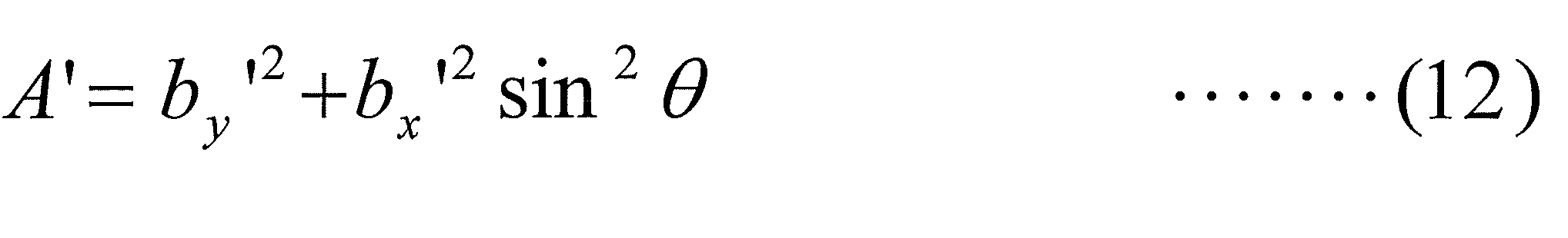
そして、係数取得部1517は、取得した係数A’についてのデータを、視点候補点算出部1519に出力する。
視点候補点算出部1519は、データData(Pc)と、角度θと、係数A’と、データData(Pb’)と、逆変換行列R-1とに基づいて、以下の数式に相当する処理を実行することで、視点候補点の座標データVp_cand(=(x,y,z))を取得する。
(1)by’>0のとき(-π/2<θ<0)
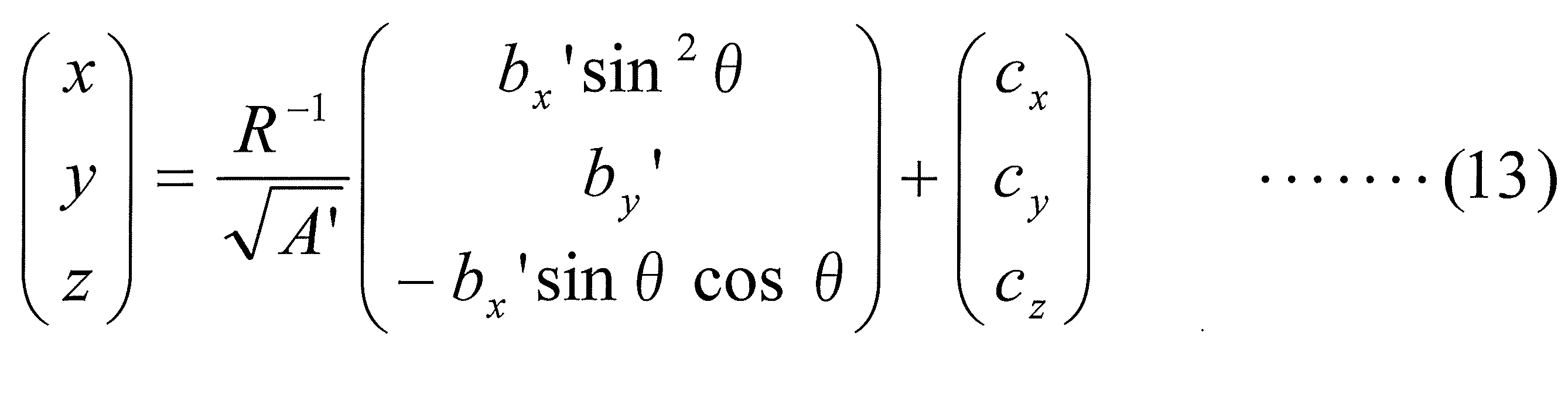
(2)by’≦0のとき(0<θ<π/2)
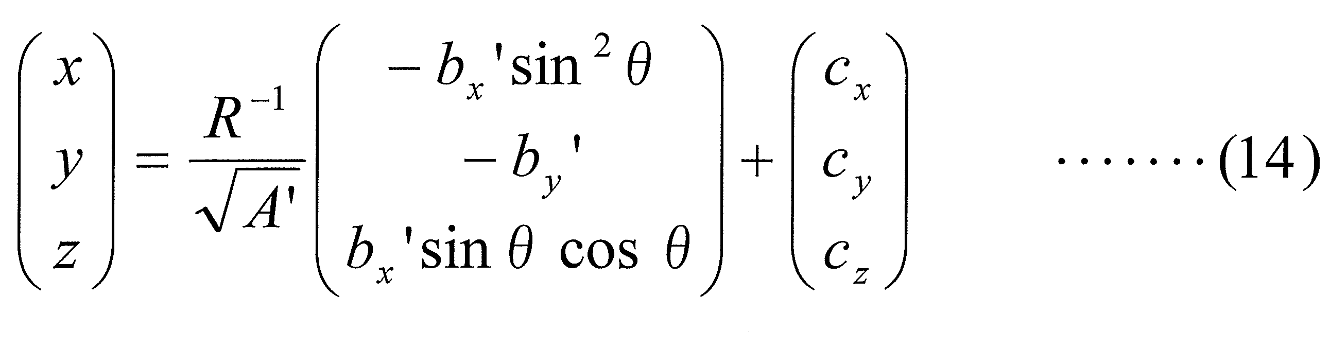
そして、視点候補点算出部1519は、上記処理により取得した視点候補点の座標データVp_cand(=(x,y,z))を投影画像取得部152に出力する。
(1)by’>0のとき(-π/2<θ<0)
上記のようにして、投影システム2000では、視点特定処理が実行される。
図29に、テスト画像Img1の一例である第3テスト画像Img1_T3を示す。第3テスト画像Img1_T3は、視点特定処理に用いられる画像である。
図29に示すように、第3テスト画像Img1_T3は、長方形の画像である。そして、第3テスト画像Img1_T3は、図29に示すように、画像の横方向(水平方向)の中央において縦方向(垂直方向)に延びる縦中心線L1vaを有し、画像の上部に水平方向(横方向)に引かれた線L2haを有し、画像の中心点に円C1を有するパターンの画像である。また、第3テスト画像Img1_T3は、図29に示すように、画像の縦方向(垂直方向)の中央において横方向(水平方向)に延びる横中心線L1haを有している。
図29に示す第3テスト画像Img1_T3は、線L1vaと線L2haとの交点が存在する部分が画像の上部である。
さらに、第3テスト画像Img1_T3は、図29に示すように、白地の正方形のパターンである第1格子パターンと、黒地の正方形のパターンである第2格子パターンとが、画像上の水平方向、および、画像上の垂直方向において、交互に配置されることで形成される格子状パターンを有している。
なお、図29に示す第3テスト画像Img1_T3は、一例であり、視点特定処理に用いられる画像は、投影したときに、ユーザーにより、画像の歪を認識できる画像であれば、他の画像であってもよい。
投影システム2000では、視点特定処理を実行する場合、第3テスト画像Img1_T3が、テスト画像記憶部2から、投影画像調整部201の第1セレクタSEL1に出力される。
そして、第1セレクタで端子0を選択し、第1切替器SW1で端子0を選択することで、第3テスト画像Img1_T3は、視点特定処理部215に入力される。
視点特定処理部215の投影画像取得部152は、3次元形状データ3D_dataと、投影部3の投影点についての情報P_prjとに基づいて、入力される第3テスト画像Img1_T3を、座標データVp_cand(=(x,y,z))により特定される視点候補点から見たときに、幾何的な歪みが発生しない画像に変換する。そして、投影画像取得部152は、変換した画像を画像D41(画像信号D41)として、第4セレクタSEL4に出力する。
そして、画像D41は、第5セレクタSEL5から投影部3に、画像Doutとして出力される。
投影部3は、画像Dout(画像D41)を傾斜天井CLに投影する。
ユーザーは、傾斜天井CLに投影されている第3テスト画像Img1_T3の歪度合いが小さくなるように、コントローラ200を操作する。
ユーザーのコントローラ200の操作に応じて、投影システム2000では、上記の視点特定処理が繰り返し実行される。
図28において、N回目(N:自然数)の視点特定処理により、特定された視点候補点をVp_cand(N)として示しており、N+1回目の視点特定処理により、特定された視点候補点をVp_cand(N+1)として示している。なお、点Pcと、ユーザーの視点Vpとを結ぶ直線上に、視点候補点Vp_cand(N+1)が存在するものとする。
ユーザーがコントローラ200を操作し、N+1回目の視点特定処理が実行されることで、視点候補点がVp_cand(N+1)となり、ユーザーの視点Vpから見たときに、幾何的な歪みのない画像が、傾斜天井CLに投影される。
図30は、投影システム2000により、N+1回目の視点特定処理が実行され、視点候補点がVp_cand(N+1)に特定された場合において、第3テスト画像Img1_T3が傾斜天井CLに投影されているときの状態(この状態を「状態5」という)を示す図である。
図30から分かるように、点Pcとユーザーの視点Vpとを結ぶ直線上に、視点候補点Vp_cand(N+1)が存在するので、状態5において、ユーザーから見たときに、第3テスト画像Img1_T3は、幾何的な歪のない画像として認識される。
以上のようにして、投影システム2000では、視点特定処理が実行され、ユーザーの視点Vpから見たときに幾何的な歪みのない画像(幾何的な歪みの低減された画像)を、傾斜天井平面CLに投影することができる。
ユーザーは、傾斜天井平面CLに投影されている画像の幾何的な歪みが十分低減されている状態(状態5)を確認し、プロジェクター装置2100における調整処理(画像の幾何的な歪みを低減させるための調整処理)を終了させる。例えば、ユーザーは、コントローラ200を操作して、プロジェクター装置2100における調整処理(画像の幾何的な歪みを低減させるための調整処理)を終了させる。
プロジェクター装置2100は、上記プロジェクター装置2100における調整処理(画像の幾何的な歪みを低減させるための調整処理)を終了させるための信号を、コントローラ200から受信する。
プロジェクター装置2100は、コントローラ200から上記信号を受信した場合、現在の設定により、画像が傾斜天井CLに投影されるようにする。
そして、プロジェクター装置2100は、画像信号(あるいは、映像信号)Dinを表示(投影)するモードに切り替えられた場合、第1セレクタSEL1において、端子1が選択されるようにし、さらに、第1切替器SW1において、端子0が選択されるようにして、画像信号Dinを、視点特定処理部215に出力する。そして、視点特定処理部215では、ユーザーの視点Vp(点Vp_cand(N+1))から見たときに幾何的な歪の発生しない画像Dinを画像に変換し、変換した画像を、画像D41として、第4セレクタSEL4に出力する。
プロジェクター装置2100は、第4セレクタSEL4において端子0が、第5セレクタにおいて端子1が、それぞれ、選択されるようにする。これにより、画像D41が画像Doutとして、投影部3に出力される。
そして、プロジェクター装置2100の投影部3より、画像Dout(画像D41)が、傾斜天井CLに投影される。
これにより、プロジェクター装置2100に入力された画像Din(あるいは、映像Din)が、傾斜天井平面CLに投影された画像(映像)は、ユーザーの視点Vpから見たときに幾何的な歪みのない(低減された)画像(映像)となる。
以上のように、投影システム2000では、表示したときの上部が分かるテスト画像を傾斜天井平面CLに投影し、ユーザーがコントローラ200により、以下の(1)~(3)の処理をプロジェクター装置2100に実行させることで、傾斜天井平面CLに投影されている画像の幾何的な歪みをなくす(低減させる)ことができる。
(1)傾斜天井平面CL内で投影画像を、ユーザーから見たときに、第1テスト画像Img1_T1の縦中心線L1vが垂直に見えるように回転させる処理(第1回転処理)。
(2)傾斜天井平面CL内で投影画像を、ユーザーから見たときに、第2テスト画像Img1_T2の横中心線L1hが水平に見えるように回転させる処理(第2回転処理)。
(3)第1回転処理の完了後において、傾斜天井CLに投影されている第1テスト画像Img1_T1の縦中心線L1vを含む第1直線と、第2回転処理の完了後において、傾斜天井CLに投影されている第2テスト画像Img1_T2の横中心線L1hを含む第2直線と、に基づいて、視点候補点を特定し、特定した視点候補点から見たときに、幾何的な歪のない画像を生成し、当該画像を投影する処理(視点特定処理)。
したがって、投影システム2000では、撮影機能を有する機器を用いることなく、傾斜投影面(例えば、傾斜天井)に投影された画像の幾何的な歪みを、容易かつ適切に、なくす(低減させる)ことができる。
<1.3:投影方法>
次に、投影システム2000で実行される投影方法について、説明する。
次に、投影システム2000で実行される投影方法について、説明する。
図31は、投影システム2000で実行される投影方法のフローチャートを示す図である。
図32は、投影システム2000で実行される投影方法の視点特定処理のフローチャートを示す図である。
以下では、図31、図32のフローチャートを参照しながら、投影システム2000で実行される投影方法について、説明する。
(ステップS1):
ステップS1において、投影システム2000では、第1回転処理が実行される。
ステップS1において、投影システム2000では、第1回転処理が実行される。
第1回転処理は、上記「(2.2.3:第1回転処理)」で説明した処理と同様の処理である。
第1回転処理では、プロジェクター装置2100により、例えば、図22に示す第1テスト画像Img1_T1が傾斜天井CLに投影される。
そして、ユーザーは、傾斜天井CLに投影されている第1テスト画像Img1_T1において、縦中心線L1vが垂直な直線に見えるようになるまで、コントローラ200を操作する。
(ステップS2):
ステップS2において、投影システム2000では、第2回転処理が実行される。
ステップS2において、投影システム2000では、第2回転処理が実行される。
第2回転処理は、上記「(2.2.5:第2回転処理)」で説明した処理と同様の処理である。
第2回転処理では、プロジェクター装置2100により、例えば、図25に示す第2テスト画像Img1_T2が傾斜天井CLに投影される。
そして、ユーザーは、傾斜天井CLに投影されている第2テスト画像Img1_T2において、横中心線L1hが水平な直線に見えるようになるまで、コントローラ200を操作する。
(ステップS3):
ステップS3において、投影システム2000では、視点特定処理が実行される。
ステップS3において、投影システム2000では、視点特定処理が実行される。
視点特定処理は、上記「(2.2.6:視点特定処理)」で説明した処理と同様の処理である。
(ステップS301):
ステップS301において、視点候補取得部151の交点算出部1511は、第1回転処理部213から出力される検出信号Det1から、第1直線のデータを取得し、状態4Aにおける縦中心線L1vを含む直線上(第1直線上)の点Paの座標データData(Pa)(=(ax,ay,az))を取得する。
ステップS301において、視点候補取得部151の交点算出部1511は、第1回転処理部213から出力される検出信号Det1から、第1直線のデータを取得し、状態4Aにおける縦中心線L1vを含む直線上(第1直線上)の点Paの座標データData(Pa)(=(ax,ay,az))を取得する。
また、交点算出部1511は、第2回転処理部214から出力される検出信号Det2から、第2直線のデータを取得し、状態4Aにおける横中心線L1hを含む直線上(第2直線上)の点Pbの座標データData(Pb)(=(bx,by,bz))を取得する。
(ステップS302):
ステップS302において、交点算出部1511は、第1直線と第2直線の交点Pcの座標データData(Pc)(=(cx,cy,cz))を取得する。例えば、交点算出部1511は、第1直線の直線方程式と、第2直線の直線方程式とを求め、求めた第1直線の直線方程式と、第2直線の直線方程式とから、算出により、第1直線と第2直線の交点Pcの座標データData(Pc)(=(cx,cy,cz))を取得する。
ステップS302において、交点算出部1511は、第1直線と第2直線の交点Pcの座標データData(Pc)(=(cx,cy,cz))を取得する。例えば、交点算出部1511は、第1直線の直線方程式と、第2直線の直線方程式とを求め、求めた第1直線の直線方程式と、第2直線の直線方程式とから、算出により、第1直線と第2直線の交点Pcの座標データData(Pc)(=(cx,cy,cz))を取得する。
なお、交点算出部1511は、図21に示したx軸、y軸、z軸で規定されるxyz空間における点Pa、点Pb、点Pcの座標データを、以下のデータとして取得するものとする。
Data(Pa)=(ax,ay,az)
Data(Pb)=(bx,by,bz)
Data(Pc)=(cx,cy,cz)
(ステップS303):
ステップS303において、係数算出部1512は、点PaのデータData(Pa)と、点PbのデータData(Pb)とから、
A=-ax×by+ay×bx
B=-ax×bz+az×bx
C=-az×by+ay×bz
に相当する処理を実行し、係数A、B、Cを取得する。
Data(Pa)=(ax,ay,az)
Data(Pb)=(bx,by,bz)
Data(Pc)=(cx,cy,cz)
(ステップS303):
ステップS303において、係数算出部1512は、点PaのデータData(Pa)と、点PbのデータData(Pb)とから、
A=-ax×by+ay×bx
B=-ax×bz+az×bx
C=-az×by+ay×bz
に相当する処理を実行し、係数A、B、Cを取得する。
(ステップS304):
ステップS304において、変換行列取得部1513は、係数A、B、Cと、点PaのデータData(Pa)とを用いて、以下の数式に相当する処理を実行することで、変換行列Rx、Ry、Rzを取得する。
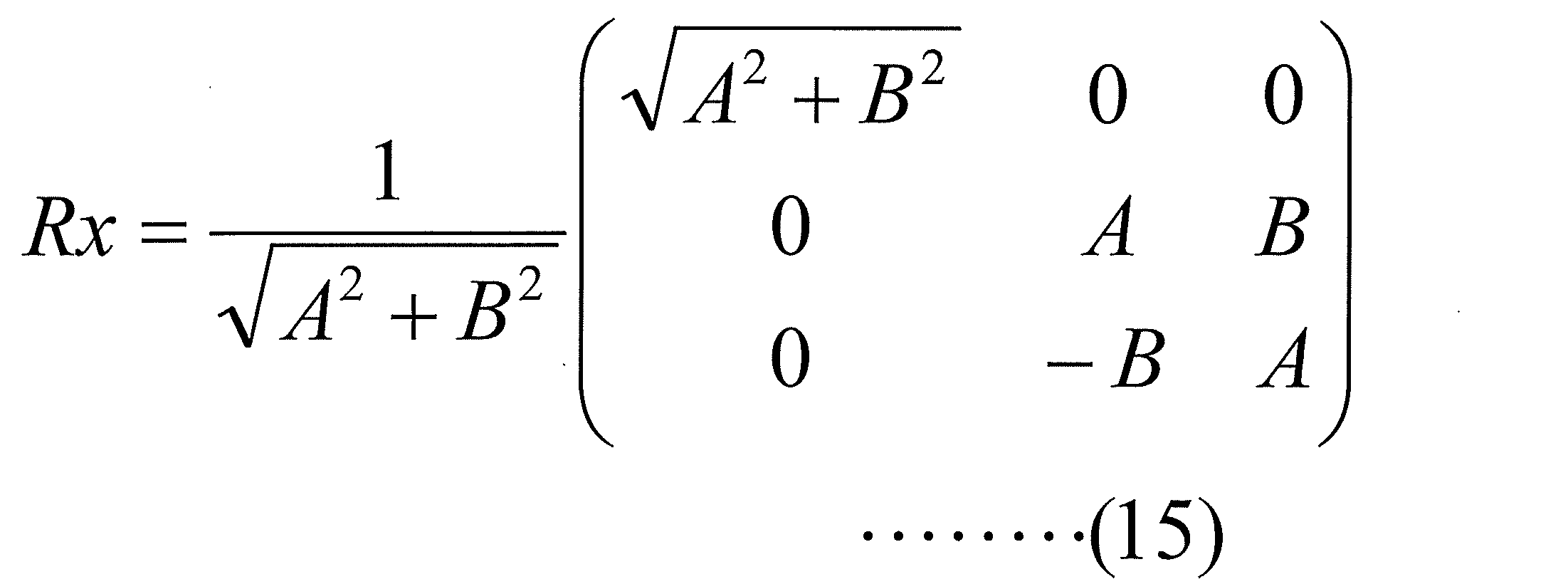
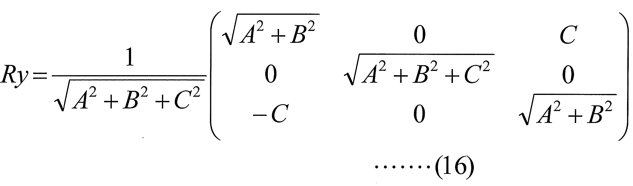

(ステップS305):
ステップS305において、変換行列合成部1514は、変換行列Rx、Ry、Rzから、
R=Rz・Ry・Rx
に相当する処理(行列の合成処理)を行い、合成行列Rを取得する。
ステップS304において、変換行列取得部1513は、係数A、B、Cと、点PaのデータData(Pa)とを用いて、以下の数式に相当する処理を実行することで、変換行列Rx、Ry、Rzを取得する。
ステップS305において、変換行列合成部1514は、変換行列Rx、Ry、Rzから、
R=Rz・Ry・Rx
に相当する処理(行列の合成処理)を行い、合成行列Rを取得する。
(ステップS306):
ステップS306において、逆変換行列取得部1515は、合成行列Rから、逆変換行列R-1を取得する。
ステップS306において、逆変換行列取得部1515は、合成行列Rから、逆変換行列R-1を取得する。
(ステップS307):
ステップS307において、変換部1516は、合成行列Rと、点PaのデータData(Pb)とを用いて、以下の数式に相当する処理を実行することで、点Pb’についてのデータ(座標データ)を取得する。
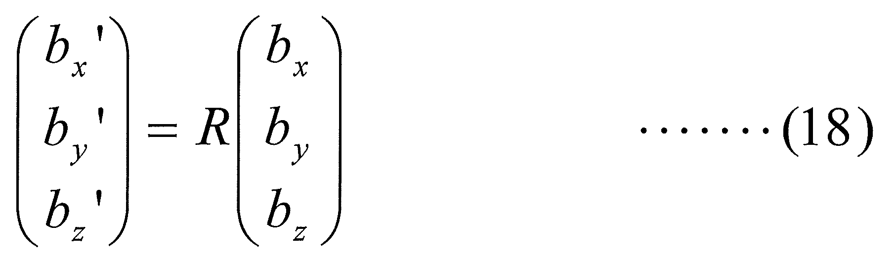
(ステップS308):
ステップS308において、角度取得部1518は、第1インターフェース6から出力される信号Sig1を入力し、信号Sig1に基づいて、角度θを取得する。角度取得部1518は、例えば、信号Sig1が入力された場合、信号Sig1の信号値に基づいて、角度θが、信号Sigが入力される前に設定されていた角度から、所定の角度だけ変化するように角度θを変化させる。
ステップS307において、変換部1516は、合成行列Rと、点PaのデータData(Pb)とを用いて、以下の数式に相当する処理を実行することで、点Pb’についてのデータ(座標データ)を取得する。
ステップS308において、角度取得部1518は、第1インターフェース6から出力される信号Sig1を入力し、信号Sig1に基づいて、角度θを取得する。角度取得部1518は、例えば、信号Sig1が入力された場合、信号Sig1の信号値に基づいて、角度θが、信号Sigが入力される前に設定されていた角度から、所定の角度だけ変化するように角度θを変化させる。
係数取得部1517は、データData(Pb’)と、角度θと、に基づいて、係数A’を、以下の数式に相当する処理により取得する。
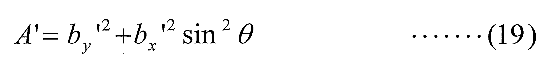
(ステップS309):
ステップS309において、視点候補点算出部1519は、データData(Pc)と、角度θと、係数A’と、データData(Pb’)と、逆変換行列R-1とに基づいて、以下の数式に相当する処理を実行することで、視点候補点の座標データVp_cand(=(x,y,z))を取得する。
(1)by’>0のとき(-π/2<θ<0)

(2)by’≦0のとき(0<θ<π/2)

(ステップS310):
ステップS310において、投影画像取得部152は、3次元形状データ3D_dataと、投影部3の投影点についての情報P_prjとに基づいて、入力される第3テスト画像Img1_T3を、座標データVp_cand(=(x,y,z))により特定される視点候補点から見たときに、幾何的な歪みが発生しない画像に変換する。
ステップS309において、視点候補点算出部1519は、データData(Pc)と、角度θと、係数A’と、データData(Pb’)と、逆変換行列R-1とに基づいて、以下の数式に相当する処理を実行することで、視点候補点の座標データVp_cand(=(x,y,z))を取得する。
(1)by’>0のとき(-π/2<θ<0)
ステップS310において、投影画像取得部152は、3次元形状データ3D_dataと、投影部3の投影点についての情報P_prjとに基づいて、入力される第3テスト画像Img1_T3を、座標データVp_cand(=(x,y,z))により特定される視点候補点から見たときに、幾何的な歪みが発生しない画像に変換する。
(ステップS311):
ステップS311において、投影部3は、ステップS310で取得された画像(画像Dout(画像D41))を傾斜天井CLに投影する。
ステップS311において、投影部3は、ステップS310で取得された画像(画像Dout(画像D41))を傾斜天井CLに投影する。
(ステップS312):
ステップS312において、ユーザーは、傾斜天井CLに投影されている第3テスト画像Img1_T3の歪度合いがない(十分小さい)か否かを判断する。
ステップS312において、ユーザーは、傾斜天井CLに投影されている第3テスト画像Img1_T3の歪度合いがない(十分小さい)か否かを判断する。
そして、傾斜天井CLに投影されている第3テスト画像Img1_T3の歪度合いが十分小さくないと判断された場合、処理を、ステップS301に戻す。一方、傾斜天井CLに投影されている第3テスト画像Img1_T3の歪度合いが十分小さいと判断された場合、処理を、終了させる(視点特定処理を完了させる)。
以上のように、投影システム2000で実行される投影方法では、表示したときの上部が分かるテスト画像を傾斜天井平面CLに投影し、ユーザーがコントローラ200により、以下の(1)~(3)の処理をプロジェクター装置2100に実行させることで、傾斜天井平面CLに投影されている画像の幾何的な歪みをなくす(低減させる)ことができる。
(1)傾斜天井平面CL内で投影画像を、ユーザーから見たときに、第1テスト画像Img1_T1の縦中心線L1vが垂直に見えるように回転させる処理(第1回転処理)。
(2)傾斜天井平面CL内で投影画像を、ユーザーから見たときに、第2テスト画像Img1_T2の横中心線L1hが水平に見えるように回転させる処理(第2回転処理)。
(3)第1回転処理の完了後において、傾斜天井CLに投影されている第1テスト画像Img1_T1の縦中心線L1vを含む第1直線と、第2回転処理の完了後において、傾斜天井CLに投影されている第2テスト画像Img1_T1の横中心線L1hを含む第2直線と、に基づいて、視点候補点を特定し、特定した視点候補点から見たときに、幾何的な歪のない画像を生成し、当該画像を投影する処理(視点特定処理)。
したがって、投影システム2000で実行される投影方法では、撮影機能を有する機器を用いることなく、傾斜投影面(例えば、傾斜天井)に投影された画像の幾何的な歪みを、容易かつ適切に、なくす(低減させる)ことができる。
≪視点特定処理の原理≫
なお、ここで、上記視点特定処理の原理について、説明する。
なお、ここで、上記視点特定処理の原理について、説明する。
3次元空間(xyz座標空間)内の異なる3点を、
A0=(ax0,ay0,az0)
B0=(bx0,by0,bz0)
C0=(cx0,cy0,cz0)
とし、ベクトルVec(C0,A0)(点C0から点A0へのベクトル)と、ベクトルVec(C0,B0)(点C0から点B0へのベクトル)とが直交して見える点をPxとする。
A0=(ax0,ay0,az0)
B0=(bx0,by0,bz0)
C0=(cx0,cy0,cz0)
とし、ベクトルVec(C0,A0)(点C0から点A0へのベクトル)と、ベクトルVec(C0,B0)(点C0から点B0へのベクトル)とが直交して見える点をPxとする。
そして、点Pxを特定することが解くべき問題(命題)である。
この問題を解くために、以下の2つの処理を行えば良い。
(1)ある点P0(例えば、z軸上のある点(0,0,1))から見て、ベクトルVec(C0,A0)と、ベクトルVec(C0,B0)とが直交して見えるようになる幾何変換を求める。なお、ここでは、説明便宜のために、点P0を(0,0,1)として、以下説明する。
P0=GmtrCnv(Px)
Px=(x,y,z)
P0=(0,0,1)
GmtrCnv:幾何変換
(2)点P0に、(1)で求めた幾何変換の逆変換を施した点からは、ベクトルVec(C0,A0)と、ベクトルVec(C0,B0)とが直交して見えるはずである。したがって、
Px=GmtrCnv-1(P0)
GmtrCnv-1:幾何変換GmtrCnvの逆変換
に相当する処理を行うことで、ベクトルVec(C0,A0)(点C0から点A0へのベクトル)と、ベクトルVec(C0,B0)(点C0から点B0へのベクトル)とが直交して見える点Pxを求めることができる。なお、以下では、m0点からm1点へのベクトルをVec(m0,m1)と表記する。
図33は、視点特定処理の原理を説明するための図である。
点A0、点B0、点C0は、異なる3点であれば、任意の点でよいが、説明便宜のために、点C0が原点(=(0,0,0))である場合について、以下説明する。つまり、図33(b)に示した場合を例に、以下説明する。つまり、
A0=(ax,ay,az)
B0=(bx,by,bz)
C0=(0,0,0)
である場合について、説明する。
A0=(ax,ay,az)
B0=(bx,by,bz)
C0=(0,0,0)
である場合について、説明する。
ベクトルVec(C0,A0)がy軸に重なり、かつ、ベクトルVec(C0,B0)がxy平面上となるように、回転処理を実行する。なお、この回転処理は、x軸を中心とする回転処理、y軸を中心とする回転処理、z軸を中心とする回転処理により実現される。
そして、回転処理後の各点を、点A0’、点B0’、点C0’とすると、点A0’、点B0’、点C0’の座標は、以下のように表すことができる。
A0’=(ax’,ay’,az’)=(0,ay’,0)
B0’=(bx’,by’,bz’)=(bx’,by’,0)
上記回転処理を行う行列は、以下のように表すことができる。
R=Rx・Ry・Rz
なお、Rxは、x軸を中心とする回転処理を表す行列であり、Ryは、y軸を中心とする回転処理を表す行列であり、Rzは、z軸を中心とする回転処理を表す行列である。
A0’=(ax’,ay’,az’)=(0,ay’,0)
B0’=(bx’,by’,bz’)=(bx’,by’,0)
上記回転処理を行う行列は、以下のように表すことができる。
R=Rx・Ry・Rz
なお、Rxは、x軸を中心とする回転処理を表す行列であり、Ryは、y軸を中心とする回転処理を表す行列であり、Rzは、z軸を中心とする回転処理を表す行列である。
図34は、上記処理を実行した後の点A0’、点B0’、点C0’(=点C0)を示す図である。
次に、ベクトルVec(C0’,A0’)がyz平面上となり、かつ、ベクトルをVec(C0’,B0’)がxz平面上となるように、y軸を中心とする回転処理、z軸を中心とする回転処理を順に実行する。
上記回転処理後の各点を点A0’’、点B0’’、点C0’’とすると、点A0’’、点B0’’、点C0’’の座標は、以下のようになる。
A0’’=(ax’’,ay’’,az’’)=(0,ay’’,az’’)
B0’’=(bx’’,by’’,bz’’)=(bx’’,0,bz’’)
図35は、上記処理を実行した後の点A0’’、点B0’’、点C0’’(=点C0)を示す図である。
A0’’=(ax’’,ay’’,az’’)=(0,ay’’,az’’)
B0’’=(bx’’,by’’,bz’’)=(bx’’,0,bz’’)
図35は、上記処理を実行した後の点A0’’、点B0’’、点C0’’(=点C0)を示す図である。
そして、上記回転処理を実行させる回転行列R’は、以下の通りである。
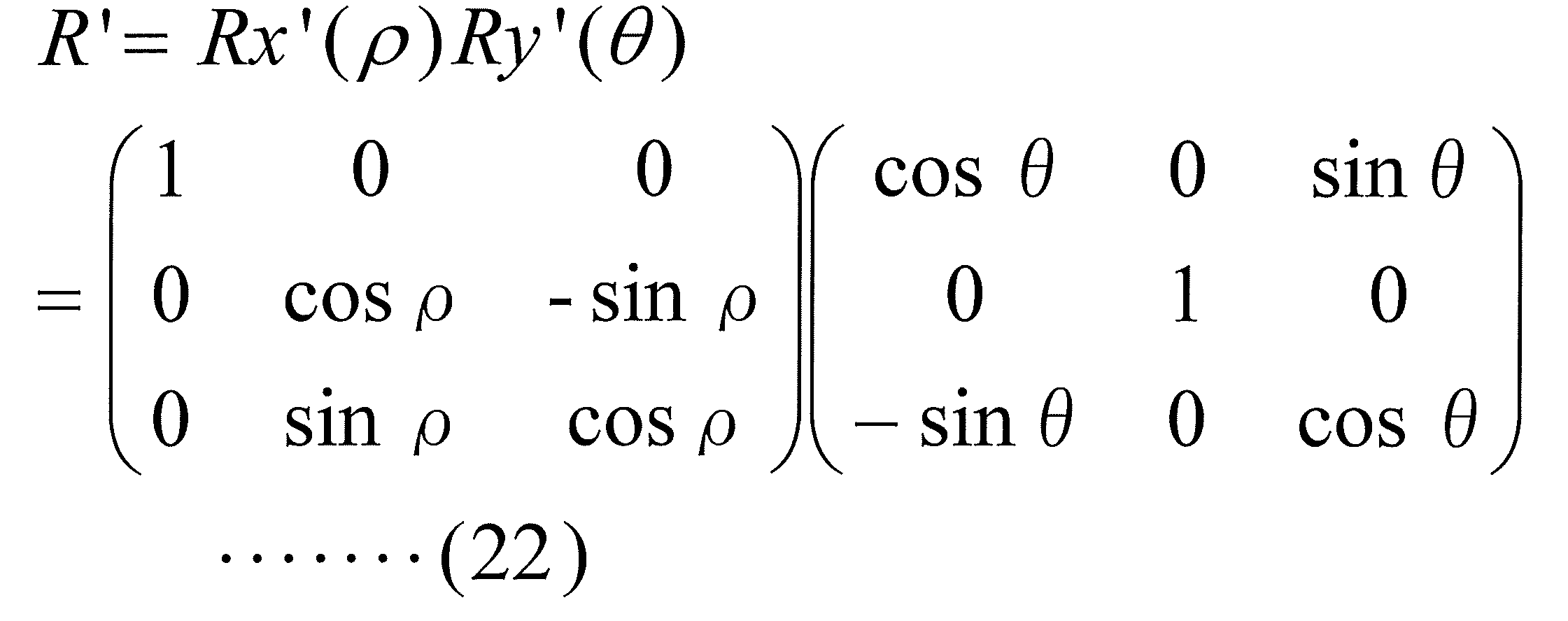
なお、ρはx軸を中心とする回転処理の回転角度であり、θはy軸を中心とする回転処理の回転角度である。
そして、回転処理前後の座標関係から、回転行列R’は、以下のように求められる。
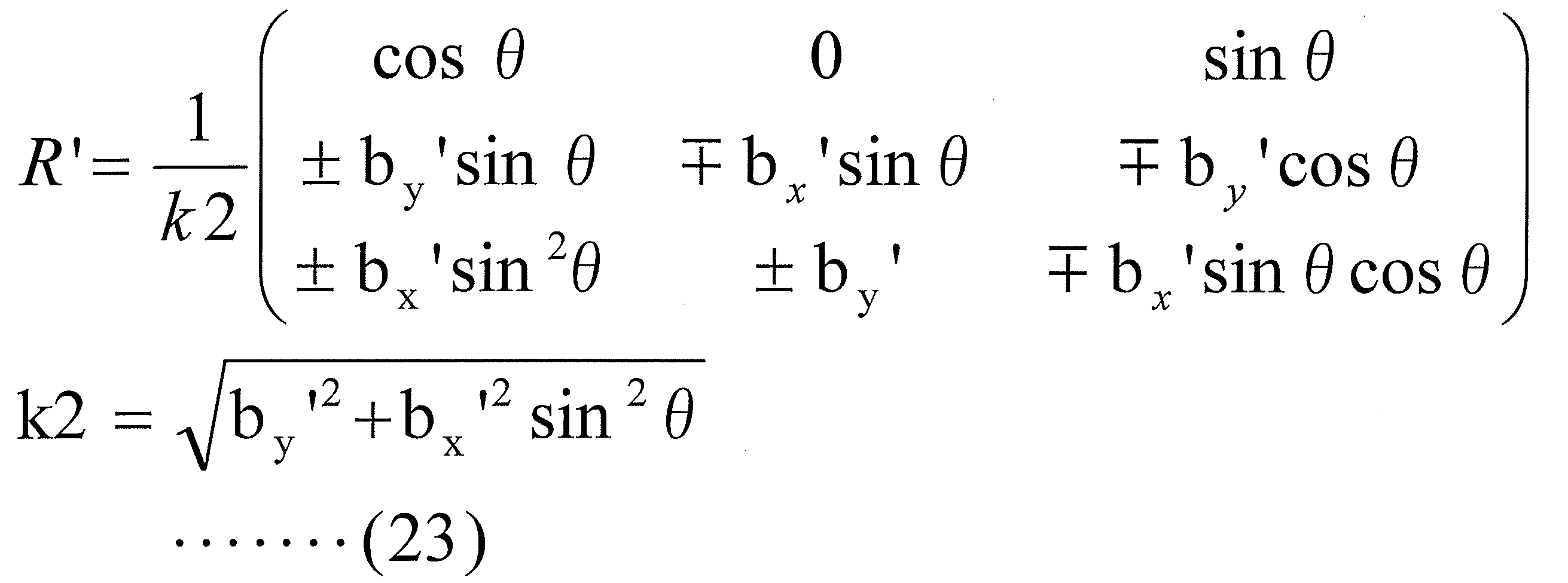
ある点P0(上記では、P0=(0,0,1))に対して、上記幾何変換の逆変換を施した点(この点を点Vp(=(x,y,z))とする)から、ベクトルVec(C0,A0)と、ベクトルVec(C0,B0)とが直交して見えるはずである。
つまり、以下の数式が成立する。
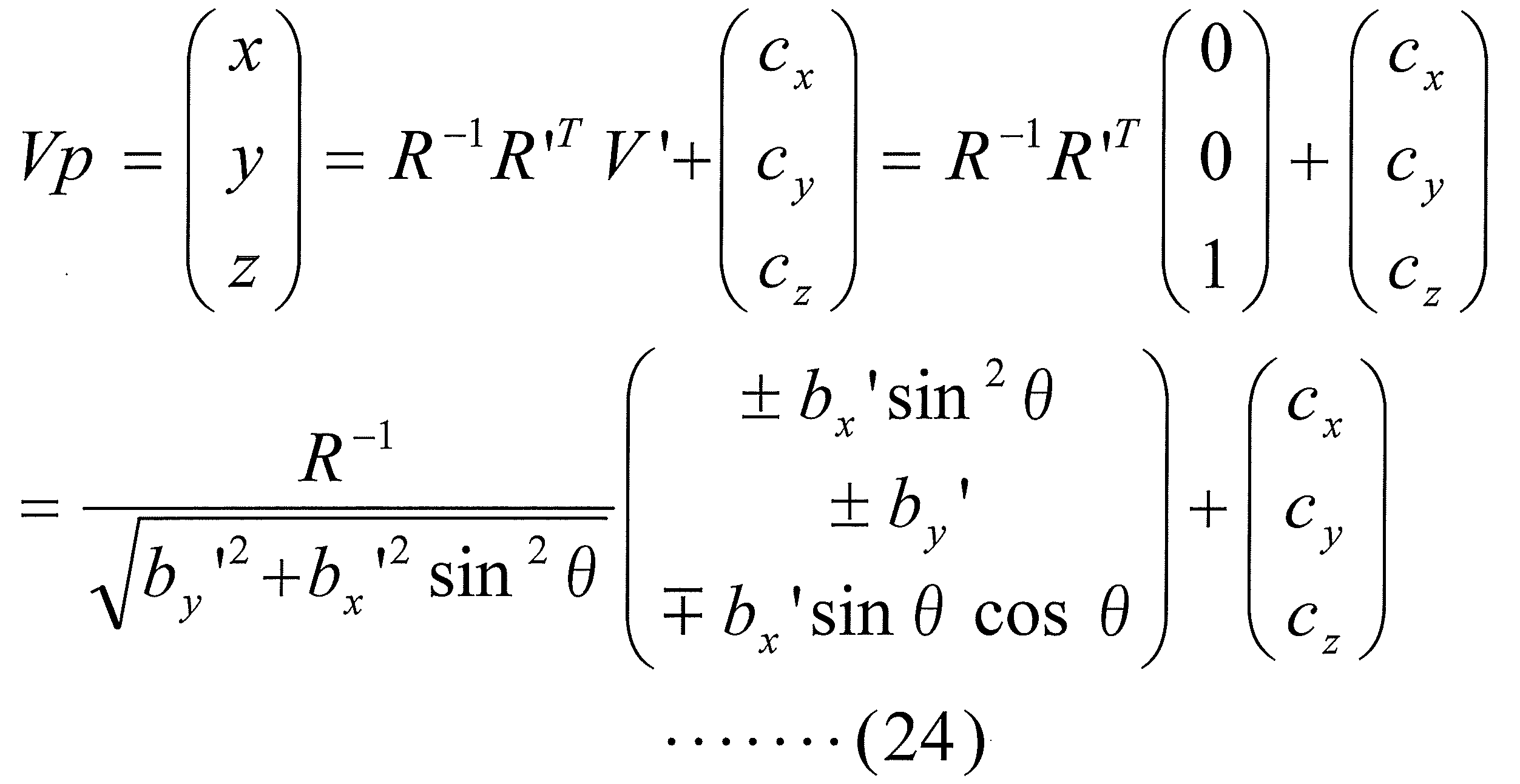
V’=(0,0,1)
図28(状態4A)における点Pcから点Paまでのベクトルを、上記のベクトルVec(C0,A0)とし、図28(状態4A)における点Pcから点Pbまでのベクトルを、上記のベクトルVec(C0,B0)とすることで、上記と同様にして、図28(状態4A)の点Pc、点Paを通る直線(第1直線)と、点Pc、点Pbを通る直線(第2直線)とが直交して見える点(視点候補点Vp)を算出することができる。
図28(状態4A)における点Pcから点Paまでのベクトルを、上記のベクトルVec(C0,A0)とし、図28(状態4A)における点Pcから点Pbまでのベクトルを、上記のベクトルVec(C0,B0)とすることで、上記と同様にして、図28(状態4A)の点Pc、点Paを通る直線(第1直線)と、点Pc、点Pbを通る直線(第2直線)とが直交して見える点(視点候補点Vp)を算出することができる。
以上の原理に基づいて、視点特定処理は実行される。
[他の実施形態]
上記実施形態(変形例を含む)において、第1インターフェース、第2インターフェース、および/または、第3インターフェースは、無線通信用のインターフェースであってもよいし、有線通信用のインターフェースであってもよい。
上記実施形態(変形例を含む)において、第1インターフェース、第2インターフェース、および/または、第3インターフェースは、無線通信用のインターフェースであってもよいし、有線通信用のインターフェースであってもよい。
また、上記実施形態では、コントローラ200が2つのボタンである第1ボタンと第2ボタンを有しており、ユーザーが第1ボタン、または、第2ボタンを操作することで、回転処理、あるいは、台形補正処理が実行される場合について、説明したが、これに限定されることはない。例えば、コントローラ200は、回転処理用のボタンを2つ有しており、かつ、台形補正処理用のボタンを2つ、別途、有していてもよい。また、コントローラ200は、ボタン以外のインターフェースを有していてもよい。例えば、コントローラ200がジョイスティックを有しており、ユーザーが当該ジョイスティックを操作することで、プロジェクター装置100に、回転処理、あるいは、台形補正処理を実行させるようにしてもよい。あるいは、コントローラ200が、タッチパネル機能付き表示パネルを有しており、表示パネル上にアイコンを表示させ、当該アイコンに、回転処理、あるいは、台形補正処理の実行機能を割り当て、当該アイコンをユーザーが操作することにより回転処理、あるいは、台形補正処理が実行されるようにしてもよい。
また、上記実施形態において、投影システムで用いたテスト画像は、図4に示した画像に限定されることはなく、投影システム1000において回転処理実行時に投影されるとき、あるいは、台形補正処理実行時に投影されるときに、ユーザーが投影画像の回転状態、台形補正状態を直感的に確認できるものであれば、テスト画像として、どのような画像を用いてもよい。
また、投影システムで用いるテスト画像は、矩形状のものに限定されることはなく、例えば、円形状や楕円状等の他の形状(他の外形)を有する画像であってもよい。
また、上記実施形態において、投影システムの投影面は、床に水平な平面の天井であるとして、説明したが、これに限定されることはなく、例えば、投影面は、ユーザーの視点からみたときに、水平な直線となる軸を回転軸として、床に水平な平面を回転させた平面としてもよい。
つまり、ユーザーから見て、左右のどちらにも傾いておらず、かつ、前方向に傾斜している平面(前方傾斜平面)を投影面としてもよい。また、ユーザーから見て、左右のどちらにも傾いておらず、かつ、後ろ方向に傾斜している平面(後方傾斜平面)を投影面としてもよい。
すなわち、本発明の投影システムにおいて、ユーザーの左眼視点と右眼視点とを結ぶ直線と平行な平面を投影面としてもよい。
このような投影面を用いる場合にも、本発明を適用することができる。
また、上記実施形態(変形例を含む)では、コントローラ200が2つのボタンである第1ボタンと第2ボタンを有しており、ユーザーが第1ボタン、または、第2ボタンを操作することで、第1回転処理、第2回転処理、台形補正処理が実行される場合について、説明したが、これに限定されることはない。例えば、コントローラ200は、第1回転処理用のボタンを2つ有しており、かつ、第2回転処理用のボタンを2つ有しており、かつ、視点特定処理用のボタンを2つ、別途、有していてもよい。また、コントローラ200は、ボタン以外のインターフェースを有していてもよい。例えば、コントローラ200がジョイスティックを有しており、ユーザーが当該ジョイスティックを操作することで、プロジェクター装置2100に、第1回転処理、第2回転処理、視点特定処理を実行させるようにしてもよい。あるいは、コントローラ200が、タッチパネル機能付き表示パネルを有しており、表示パネル上にアイコンを表示させ、当該アイコンに、第1回転処理、第2回転処理、視点特定処理の実行機能を割り当て、当該アイコンをユーザーが操作することにより第1回転処理、第2回転処理、台形補正処理が実行されるようにしてもよい。
また、上記実施形態において、投影システムの投影面は、図21等に示した傾斜の平面の天井であるとして、説明したが、これに限定されることはなく、投影面は、床に対して(あるいは、ユーザーの視点に対して)、任意の方向、角度の傾斜であってもよい。この場合であっても、上記と同様の処理を行うことで、傾斜平面を投影面として、ユーザーの視点から見たときに、幾何的な歪みのない画像(幾何的な歪みの低減された画像)を投影することができる。
また、「水平」、「垂直」、「縦」、「横」、「平面」等の文言は、厳密な意味での、「水平」、「垂直」、「縦」、「横」等の場合のみを含むのではなく、「略水平」、「略垂直」、「略縦」、「略横」、「略平面」等を含む概念の文言である。また、「水平」、「垂直」、「縦」、「横」、「平面」等の文言は、設計誤差や測定誤差を許容する概念を含む文言である。
上記実施形態で説明した投影システム、プロジェクター装置、コントローラにおいて、各ブロックは、LSIなどの半導体装置により個別に1チップ化されても良いし、一部又は全部を含むように1チップ化されても良い。
なお、ここでは、LSIとしたが、集積度の違いにより、IC、システムLSI、スーパーLSI、ウルトラLSIと呼称されることもある。
また、集積回路化の手法はLSIに限るものではなく、専用回路又は汎用プロセサで実現してもよい。LSI製造後に、プログラムすることが可能なFPGA(Field Programmable Gate Array)や、LSI内部の回路セルの接続や設定を再構成可能なリコンフィギュラブル・プロセッサーを利用しても良い。
また、上記各実施形態の各機能ブロック(各機能部)の処理の一部または全部は、プログラムにより実現されるものであってもよい。そして、上記各実施形態の各機能ブロックの処理の一部または全部は、コンピュータにおいて、中央演算装置(CPU)により行われる。また、それぞれの処理を行うためのプログラムは、ハードディスク、ROMなどの記憶装置に格納されており、ROMにおいて、あるいはRAMに読み出されて実行される。
例えば、図36に示すような構成により、上記各実施形態の各機能ブロック(各機能部)の処理の一部または全部が実行されるものであっても良い。
また、上記実施形態の各処理をハードウェアにより実現してもよいし、ソフトウェア(OS(オペレーティングシステム)、ミドルウェア、あるいは、所定のライブラリとともに実現される場合を含む。)により実現してもよい。さらに、ソフトウェアおよびハードウェアの混在処理により実現しても良い。
また、上記実施形態における処理方法の実行順序は、必ずしも、上記実施形態の記載に制限されるものではなく、発明の要旨を逸脱しない範囲で、実行順序を入れ替えることができるものである。
また、上記実施形態における調整処理(画像の幾何的な歪みを低減させるための調整処理)において、補正処理、回転処理、台形補正処理の処理内容が決まれば、実際の投影時には、必ずしも、補正処理、回転処理、台形補正処理を分けて実行する必要はなく、全ての変換を一括で実施する画像処理を実行するようにしてもよい。
また、上記実施形態における調整処理(画像の幾何的な歪みを低減させるための調整処理)において、補正処理、第1回転処理、第2回転処理、および、視点特定処理の処理内容が決まれば、実際の投影時には、必ずしも、補正処理、第1回転処理、第2回転処理、および、視点特定処理を分けて実行する必要はなく、全ての変換を一括で実施する画像処理を実行するようにしてもよい。
前述した方法をコンピュータに実行させるコンピュータプログラム及びそのプログラムを記録したコンピュータ読み取り可能な記録媒体は、本発明の範囲に含まれる。ここで、コンピュータ読み取り可能な記録媒体としては、例えば、フレキシブルディスク、ハードディスク、CD-ROM、MO、DVD、DVD-ROM、DVD-RAM、大容量DVD、次世代DVD、半導体メモリを挙げることができる。
上記コンピュータプログラムは、上記記録媒体に記録されたものに限られず、電気通信回線、無線又は有線通信回線、インターネットを代表とするネットワーク等を経由して伝送されるものであってもよい。
また、文言「部」は、「サーキトリー(circuitry)」を含む概念であってもよい。サーキトリーは、ハードウェア、ソフトウェア、あるいは、ハードウェアおよびソフトウェアの混在により、その全部または一部が、実現されるものであってもよい。
なお、本発明の具体的な構成は、前述の実施形態に限られるものではなく、発明の要旨を逸脱しない範囲で種々の変更および修正が可能である。
1000、2000 投影システム
100、100A、2100 プロジェクター装置
1、1A、201 投影画像調整部
2 テスト画像記憶部
3 投影部
4 3次元形状測定部
5 3次元形状データ記憶部
6 第1インターフェース
200 コントローラ
100、100A、2100 プロジェクター装置
1、1A、201 投影画像調整部
2 テスト画像記憶部
3 投影部
4 3次元形状測定部
5 3次元形状データ記憶部
6 第1インターフェース
200 コントローラ
Claims (18)
- 左眼視点と右眼視点とを結ぶ直線と平行な平面を投影面とし、ユーザーの視点から見たときに幾何学的な画像歪みが低減された状態となるように画像を投影する投影システムであって、
前記投影面に画像を投影する投影部であって、テスト画像を投影する前記投影部と、
前記投影面の3次元形状を測定する3次元形状測定部と、
ユーザーの操作に基づく制御信号を生成するコントローラと、
(1)前記3次元形状測定部により計測された3次元形状データに基づいて、前記投影部の投影軸と前記投影面との交点である投影中心点を通り、前記投影面の法線上の点である第1点から見たときに、幾何学的な画像歪みが低減された状態とするように、前記テスト画像に対して画像変換処理である補正処理を実行し、
(2)前記制御信号に従い回転角度を決定し、前記第1点から前記投影面を見たときに、前記補正処理後の前記テスト画像の前記投影部による前記投影面への投影画像が前記投影中心点を中心として、前記回転角度だけ回転した画像となるように、前記補正処理後の前記テスト画像に対して画像変換処理である回転処理を実行する投影画像調整部と、
を備える投影システム。 - 前記テスト画像は、表示画面に表示されている状態において、画像上の縦方向に延びる縦基準線を含む画像であり、
前記投影画像調整部は、
前記制御信号に従い歪み低減量を決定し、前記投影面に投影された前記投影画像の前記縦基準線を含む平面であって、前記投影面と垂直な平面内に含まれる点から前記投影面を見たときに、前記歪み低減量に相当する分だけ、前記縦基準線上の1つの点である第1直交点を通り、前記縦基準線と直交する方向の前記投影画像の長さである第1距離と、前記縦基準線上の前記第1直交点以外の点である第2直交点を通り、前記縦基準線と直交する方向の前記投影画像の長さである第2距離との差が小さくなるように、前記回転処理後の前記テスト画像に対して画像変換処理である台形補正処理を実行する、
請求項1に記載の投影システム。 - 前記投影画像調整部は、
前記回転処理および前記台形補正処理の少なくとも一方の処理が実行された前記テスト画像を前記投影面に投影したときの画像の投影状態を調整するための微調整部を備える、
請求項2に記載の投影システム。 - 前記テスト画像は、
表示画面に表示されている状態において、画像上の上部を判別することができるパターンを含む画像である、
請求項2または3に記載の投影システム。 - 前記テスト画像は、
複数の正方形の格子パターンからなる格子状パターンを含む画像である、
請求項2から4のいずれかに記載の投影システム。 - 前記テスト画像は、
第1の模様を有する第1格子パターンと、第2の模様を有する第2格子パターンとが、幾何学的な歪みがない状態において、前記テスト画像上の第1方向、および、前記テスト画像上において前記第1方向と直交する第2方向において、交互に配置されることで形成される格子状パターンを含む画像である、
請求項5に記載の投影システム。 - 請求項1から6のいずれかに記載の投影システムに用いられるプロジェクター装置であって、
前記投影部と、前記投影画像調整部とを備える、
プロジェクター装置。 - 左眼視点と右眼視点とを結ぶ直線と平行な平面を投影面とし、ユーザーの視点から見たときに幾何学的な画像歪みが低減された状態となるように画像を投影する投影方法をコンピュータに実行させるためのプログラムであって、
前記投影面にテスト画像を投影する投影ステップと、
前記投影面の3次元形状を測定する3次元形状測定ステップと、
ユーザーの操作に基づく制御信号を生成するステップと、
(1)前記3次元形状測定ステップにより計測された3次元形状データに基づいて、前記投影ステップにおける投影軸と前記投影面との交点である投影中心点を通り、前記投影面の法線上の点である第1点から見たときに、幾何学的な画像歪みが低減された状態とするように、前記テスト画像に対して画像変換処理である補正処理を実行し、
(2)前記制御信号に従い回転角度を決定し、前記第1点から前記投影面を見たときに、前記補正処理後の前記テスト画像の前記投影ステップによる前記投影面への投影画像が前記投影中心点を中心として、前記回転角度だけ回転した画像となるように、前記補正処理後の前記テスト画像に対して画像変換処理である回転処理を実行する投影画像調整ステップと、
を備える投影方法をコンピュータに実行させるためのプログラム。 - 前記テスト画像は、表示画面に表示されている状態において、画像上の縦方向に延びる縦基準線を含む画像であり、
前記投影画像調整ステップは、
前記制御信号に従い歪み低減量を決定し、前記投影面に投影された前記投影画像の前記縦基準線を含む平面であって、前記投影面と垂直な平面内に含まれる点から前記投影面を見たときに、前記歪み低減量に相当する分だけ、前記縦基準線と直交する方向に発生している幾何的な歪みが低減されるように、前記回転処理後の前記テスト画像に対して画像変換処理である台形補正処理を実行する、
請求項8に記載の投影方法をコンピュータに実行させるためのプログラム。 - 左眼視点と右眼視点とを含む平面に平行な平面であって、右眼角膜および左眼角膜の共通の接平面である前記平面に対して、傾斜した平面を投影面とし、ユーザーの視点から見たときに幾何学的な画像歪みが低減された状態となるように画像を投影する投影システムであって、
前記投影面に画像を投影する投影部であって、画像の垂直方向を規定する縦基準線を有する第1テスト画像を投影するとともに、画像の水平方向を規定する横基準線を有する第2テスト画像を投影する前記投影部と、
前記投影面の3次元形状を測定する3次元形状測定部と、
ユーザーの操作に基づく制御信号を生成するコントローラと、
(1A)前記3次元形状測定部により計測された3次元形状データに基づいて、前記投影部の投影軸と前記投影面との交点である投影中心点を通り、前記投影面の法線上の点である第1点から見たときに、幾何学的な画像歪みが低減された状態とするように、前記第1テスト画像に対して画像変換処理である補正処理を実行し、
(2A)前記制御信号に従い第1回転角度を決定し、前記第1点から前記投影面を見たときに、前記補正処理後の前記第1テスト画像の前記投影部による前記投影面への投影画像が前記投影中心点を中心として、前記第1回転角度だけ回転した画像となるように、前記補正処理後の前記第1テスト画像に対して画像変換処理である第1回転処理を実行し、
(1B)前記3次元形状測定部により計測された3次元形状データに基づいて、前記投影部の投影軸と前記投影面との交点である投影中心点を通り、前記投影面の法線上の点である第1点から見たときに、幾何学的な画像歪みが低減された状態とするように、前記第2テスト画像に対して画像変換処理である補正処理を実行し、
(2B)前記制御信号に従い第2回転角度を決定し、前記第1点から前記投影面を見たときに、前記補正処理後の前記第2テスト画像の前記投影部による前記投影面への投影画像が前記投影中心点を中心として、前記第2回転角度だけ回転した画像となるように、前記補正処理後の前記第2テスト画像に対して画像変換処理である第2回転処理を実行し、
(3)前記第1回転処理後の前記第1テスト画像の前記投影面上の前記縦基準線を含む直線である第1直線と、前記第2回転処理後の前記第2テスト画像の前記投影面上の前記縦基準線を含む直線である第2直線とに基づいて、前記第1直線と前記第2直線とが直交して見える視点候補点を決定し、決定した視点候補点から見たときに幾何学的な画像歪みが低減された状態とするように、前記投影面に投影される画像を変換する視点特定処理を実行する、投影画像調整部と、
を備える投影システム。 - 前記投影画像調整部は、
前記投影部の光軸をz軸とし、前記投影部の光軸を法線とする平面をxy平面とするようにx軸およびy軸を設定したxyz座標空間において、
前記第1回転処理後の前記第1テスト画像の前記投影面上の前記縦基準線を含む直線である第1直線上の点を点Paとし、点Paの座標を(ax,ay,az)とし、
前記第2回転処理後の前記第2テスト画像の前記投影面上の前記横基準線を含む直線である第2直線上の点を点Pbとし、点Pbの座標を(bx,by,bz)とし、
前記第1直線と前記第2直線との交点を点Pcとして算出し、算出した点Pcの座標を(cx,cy,cz)としたとき、
A=-ax×by+ay×bx
B=-ax×bz+az×bx
C=-az×by+ay×bz
に相当する処理を実行し、係数A、B、Cを取得し、
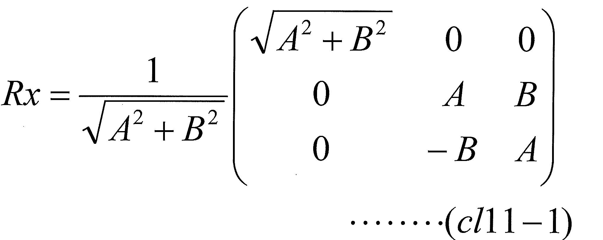
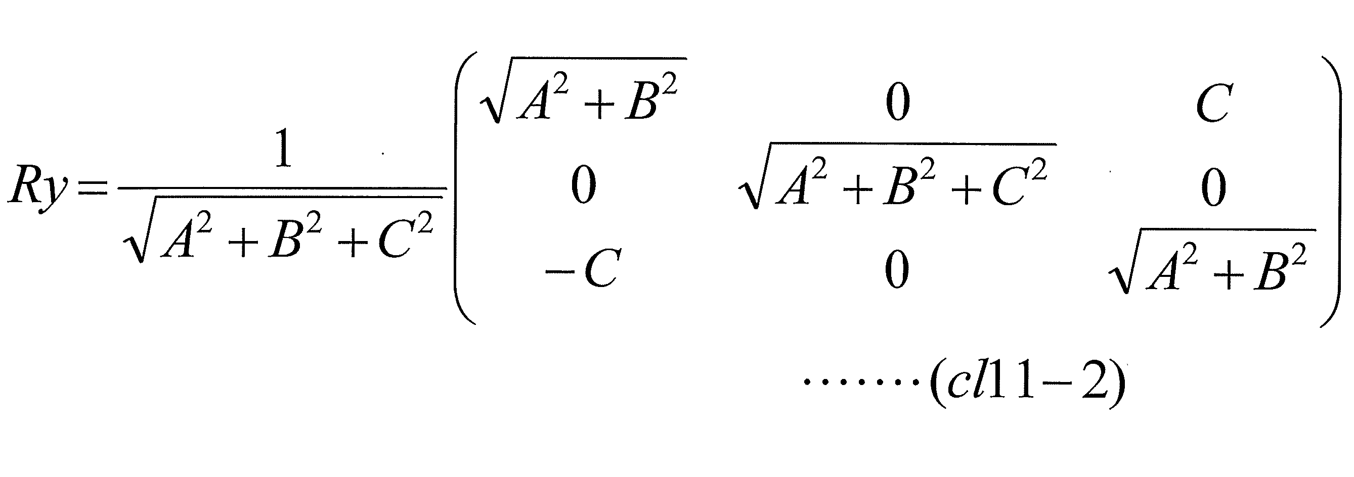 により、回転行列Rx,Ry、Rzを取得し、
回転行列Rx,Ry、Rzの合成行列をR
R=Rz・Ry・Rx
に相当する処理を実行することで取得し、
前記回転行列の逆行列をR-1として取得し、
点Pbの座標(bx,by,bz)に対して、前記合成行列により変換した点を点Pb’として取得し、点Pb’の座標を(bx’,by’,bz’)として取得し、
前記コントローラからの前記制御信号に基づいて、角度θを決定し、
係数A’を
により取得し、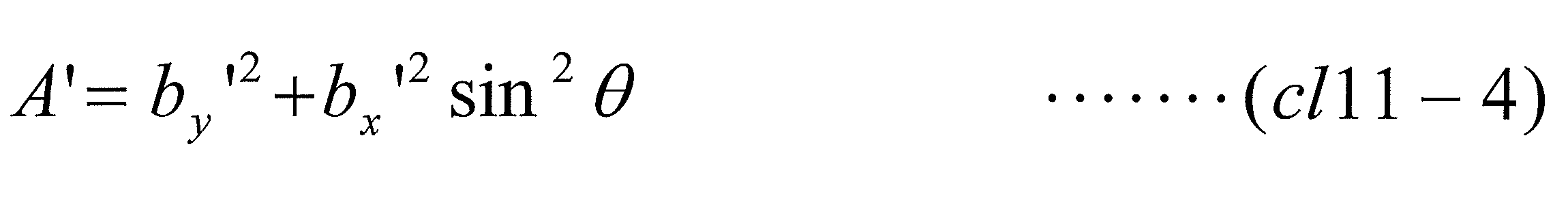
前記視点候補点の座標(x,y,z)を、
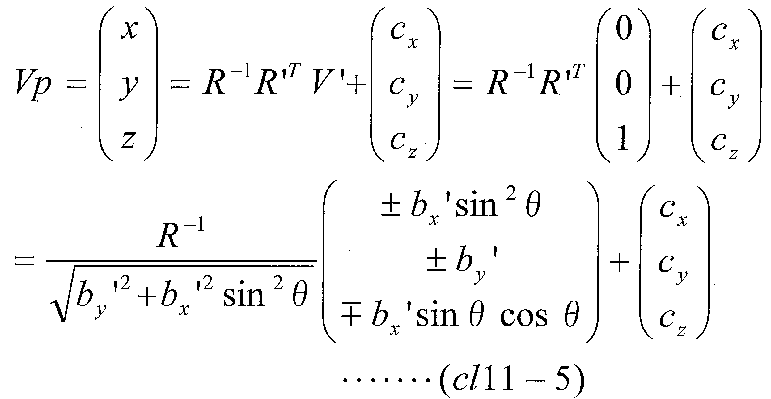 V’=(0,0,1)
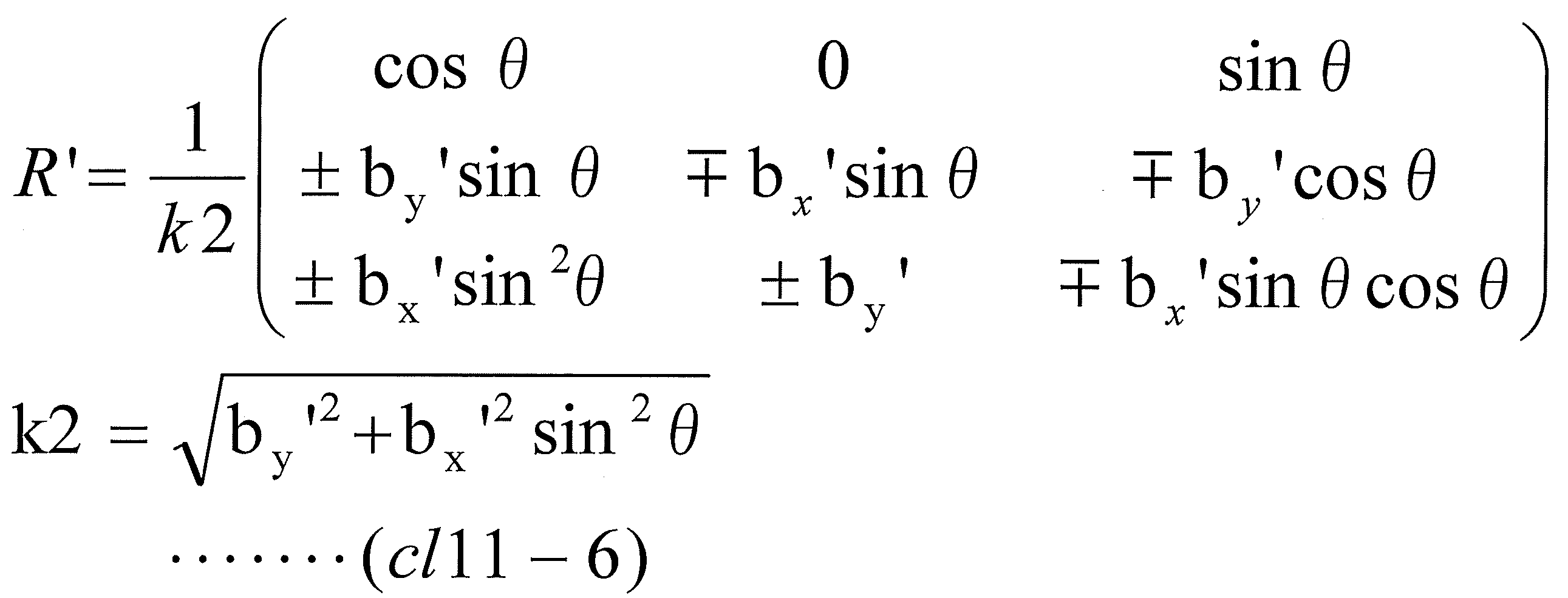
により算出する、
請求項10に記載の投影システム。 - 前記第1テスト画像は、表示画面に表示されている状態において、前記第1テスト画像の中心点を通る前記縦基準線を含む、
請求項10又は11に記載の投影システム。 - 前記第2テスト画像は、表示画面に表示されている状態において、前記第2テスト画像の中心点を通る前記横基準線を含む、
請求項10又は11に記載の投影システム。 - 前記第1テスト画像は、
表示画面に表示されている状態において、画像上の上部を判別することができるパターンを含む画像である、
請求項10から13のいずれかに記載の投影システム。 - 前記投影部は、
前記視点特定処理が実行される場合、
複数の正方形の格子パターンからなる格子状パターンを含む第3テスト画像を投影する、
請求項10から14のいずれかに記載の投影システム。 - 前記第3テスト画像は、
第1の模様を有する第1格子パターンと、第2の模様を有する第2格子パターンとが、幾何学的な歪みがない状態において、前記テスト画像上の第1方向、および、前記テスト画像上において前記第1方向と直交する第2方向において、交互に配置されることで形成される格子状パターンを含む画像である、
請求項15に記載の投影システム。 - 請求項10から16のいずれかに記載の投影システムに用いられるプロジェクター装置であって、
前記投影部と、前記投影画像調整部とを備える、
プロジェクター装置。 - ユーザーの操作に基づく制御信号を生成するコントローラを用いて実行される投影方法であって、左眼視点と右眼視点とを含む平面に平行な平面であって、右眼角膜および左眼角膜の共通の接平面である前記平面に対して、傾斜した平面を投影面とし、ユーザーの視点から見たときに幾何学的な画像歪みが低減された状態となるように画像を投影する投影方法をコンピュータで実行するためのプログラムであって、
前記投影面に画像を投影する投影ステップであって、画像の垂直方向を規定する縦基準線を有する第1テスト画像を投影するとともに、画像の水平方向を規定する横基準線を有する第2テスト画像を投影する前記投影ステップと、
前記投影面の3次元形状を測定する3次元形状測定ステップと、
と、
(1A)前記3次元形状測定ステップにより計測された3次元形状データに基づいて、前記投影ステップで画像を投影するための投影軸と前記投影面との交点である投影中心点を通り、前記投影面の法線上の点である第1点から見たときに、幾何学的な画像歪みが低減された状態とするように、前記第1テスト画像に対して画像変換処理である補正処理を実行し、
(2A)前記制御信号に従い第1回転角度を決定し、前記第1点から前記投影面を見たときに、前記補正処理後の前記第1テスト画像の前記投影ステップによる前記投影面への投影画像が前記投影中心点を中心として、前記第1回転角度だけ回転した画像となるように、前記補正処理後の前記第1テスト画像に対して画像変換処理である第1回転処理を実行し、
(1B)前記3次元形状測定ステップにより計測された3次元形状データに基づいて、前記投影ステップで画像を投影するための投影軸と前記投影面との交点である投影中心点を通り、前記投影面の法線上の点である第1点から見たときに、幾何学的な画像歪みが低減された状態とするように、前記第2テスト画像に対して画像変換処理である補正処理を実行し、
(2B)前記制御信号に従い第2回転角度を決定し、前記第1点から前記投影面を見たときに、前記補正処理後の前記第2テスト画像の前記投影ステップによる前記投影面への投影画像が前記投影中心点を中心として、前記第2回転角度だけ回転した画像となるように、前記補正処理後の前記第2テスト画像に対して画像変換処理である第2回転処理を実行し、
(3)前記第1回転処理後の前記第1テスト画像の前記投影面上の前記縦基準線を含む直線である第1直線と、前記第2回転処理後の前記第2テスト画像の前記投影面上の前記縦基準線を含む直線である第2直線とに基づいて、前記第1直線と前記第2直線とが直交して見える視点候補点を決定し、決定した視点候補点から見たときに幾何学的な画像歪みが低減された状態とするように、前記投影面に投影される画像を変換する視点特定処理を実行する、投影画像調整ステップと、
を備える投影方法をコンピュータで実行するためのプログラム。
Priority Applications (2)
| Application Number | Priority Date | Filing Date | Title |
|---|---|---|---|
| EP16772050.7A EP3280136B1 (en) | 2015-03-30 | 2016-03-01 | Projection systems and projection methods |
| US15/719,329 US9928580B2 (en) | 2015-03-30 | 2017-09-28 | Projection system, projector apparatus, and projection method |
Applications Claiming Priority (4)
| Application Number | Priority Date | Filing Date | Title |
|---|---|---|---|
| JP2015-068987 | 2015-03-30 | ||
| JP2015068987A JP6624799B2 (ja) | 2015-03-30 | 2015-03-30 | 投影システム、プロジェクター装置、および、プログラム |
| JP2016007581A JP6624942B2 (ja) | 2016-01-19 | 2016-01-19 | 投影システム、プロジェクター装置、および、プログラム |
| JP2016-007581 | 2016-01-19 |
Related Child Applications (1)
| Application Number | Title | Priority Date | Filing Date |
|---|---|---|---|
| US15/719,329 Continuation US9928580B2 (en) | 2015-03-30 | 2017-09-28 | Projection system, projector apparatus, and projection method |
Publications (1)
| Publication Number | Publication Date |
|---|---|
| WO2016158166A1 true WO2016158166A1 (ja) | 2016-10-06 |
Family
ID=57004521
Family Applications (1)
| Application Number | Title | Priority Date | Filing Date |
|---|---|---|---|
| PCT/JP2016/056253 Ceased WO2016158166A1 (ja) | 2015-03-30 | 2016-03-01 | 投影システム、プロジェクター装置、および、プログラム |
Country Status (3)
| Country | Link |
|---|---|
| US (1) | US9928580B2 (ja) |
| EP (1) | EP3280136B1 (ja) |
| WO (1) | WO2016158166A1 (ja) |
Cited By (2)
| Publication number | Priority date | Publication date | Assignee | Title |
|---|---|---|---|---|
| CN108303117A (zh) * | 2017-01-12 | 2018-07-20 | 中国农业大学 | 一种基于后方交会测量的云镜摄系统参数测量方法及系统 |
| CN113923428A (zh) * | 2021-11-23 | 2022-01-11 | 中国航空工业集团公司洛阳电光设备研究所 | 一种平显投影装置投影精度快速校准终端及校准方法 |
Families Citing this family (5)
| Publication number | Priority date | Publication date | Assignee | Title |
|---|---|---|---|---|
| JP6636252B2 (ja) * | 2015-03-19 | 2020-01-29 | 株式会社メガチップス | 投影システム、プロジェクター装置、撮像装置、および、プログラム |
| CN105093789B (zh) * | 2015-07-03 | 2021-05-11 | 中兴通讯股份有限公司 | 一种实现投影面梯形失真校正的方法及装置和投影仪 |
| JP2017055178A (ja) * | 2015-09-07 | 2017-03-16 | ソニー株式会社 | 情報処理装置、情報処理方法、およびプログラム |
| JP6780315B2 (ja) * | 2016-06-22 | 2020-11-04 | カシオ計算機株式会社 | 投影装置、投影システム、投影方法及びプログラム |
| EP3622483B1 (en) * | 2017-05-09 | 2025-06-25 | Koninklijke KPN N.V. | Coding spherical video data |
Citations (5)
| Publication number | Priority date | Publication date | Assignee | Title |
|---|---|---|---|---|
| JP2005123855A (ja) * | 2003-10-16 | 2005-05-12 | Nippon Telegr & Teleph Corp <Ntt> | 情報提示装置、情報提示システム、情報提示方法および情報提示プログラム |
| JP2008085748A (ja) * | 2006-09-28 | 2008-04-10 | Victor Co Of Japan Ltd | 画像投影表示装置 |
| JP2009135921A (ja) * | 2007-11-06 | 2009-06-18 | Panasonic Corp | 画像投影装置及び画像投影方法 |
| JP2013026824A (ja) * | 2011-07-21 | 2013-02-04 | Mitsubishi Precision Co Ltd | 映像の歪みを補正する方法、映像の歪みを補正する装置、模擬視界表示装置及び操縦訓練のためのシミュレータ |
| JP2014131091A (ja) * | 2012-12-28 | 2014-07-10 | Ricoh Co Ltd | 校正装置、プロジェクタ、3次元スキャナ、校正方法、プログラム、及び記憶媒体 |
Family Cites Families (6)
| Publication number | Priority date | Publication date | Assignee | Title |
|---|---|---|---|---|
| KR20050050614A (ko) * | 2002-10-08 | 2005-05-31 | 소니 가부시끼 가이샤 | 화상 변환 장치, 화상 변환 방법, 및, 화상 투사 장치 |
| JP2006033357A (ja) | 2004-07-15 | 2006-02-02 | Olympus Corp | 画像変換装置及び映像投影装置 |
| US7857461B2 (en) | 2007-11-06 | 2010-12-28 | Panasonic Corporation | Projector and projection method |
| JP2014131257A (ja) * | 2012-11-27 | 2014-07-10 | Ricoh Co Ltd | 画像補正システム、画像補正方法及びプログラム |
| EP2929574A2 (en) | 2012-12-07 | 2015-10-14 | Bayer Materialscience AG | Electroactive polymer actuated aperture |
| CN103974048B (zh) * | 2014-04-28 | 2016-05-04 | 京东方科技集团股份有限公司 | 控制可穿戴设备投影的方法及装置、可穿戴设备 |
-
2016
- 2016-03-01 WO PCT/JP2016/056253 patent/WO2016158166A1/ja not_active Ceased
- 2016-03-01 EP EP16772050.7A patent/EP3280136B1/en active Active
-
2017
- 2017-09-28 US US15/719,329 patent/US9928580B2/en active Active
Patent Citations (5)
| Publication number | Priority date | Publication date | Assignee | Title |
|---|---|---|---|---|
| JP2005123855A (ja) * | 2003-10-16 | 2005-05-12 | Nippon Telegr & Teleph Corp <Ntt> | 情報提示装置、情報提示システム、情報提示方法および情報提示プログラム |
| JP2008085748A (ja) * | 2006-09-28 | 2008-04-10 | Victor Co Of Japan Ltd | 画像投影表示装置 |
| JP2009135921A (ja) * | 2007-11-06 | 2009-06-18 | Panasonic Corp | 画像投影装置及び画像投影方法 |
| JP2013026824A (ja) * | 2011-07-21 | 2013-02-04 | Mitsubishi Precision Co Ltd | 映像の歪みを補正する方法、映像の歪みを補正する装置、模擬視界表示装置及び操縦訓練のためのシミュレータ |
| JP2014131091A (ja) * | 2012-12-28 | 2014-07-10 | Ricoh Co Ltd | 校正装置、プロジェクタ、3次元スキャナ、校正方法、プログラム、及び記憶媒体 |
Cited By (4)
| Publication number | Priority date | Publication date | Assignee | Title |
|---|---|---|---|---|
| CN108303117A (zh) * | 2017-01-12 | 2018-07-20 | 中国农业大学 | 一种基于后方交会测量的云镜摄系统参数测量方法及系统 |
| CN108303117B (zh) * | 2017-01-12 | 2020-06-02 | 中国农业大学 | 一种基于后方交会测量的云镜摄系统参数测量方法及系统 |
| CN113923428A (zh) * | 2021-11-23 | 2022-01-11 | 中国航空工业集团公司洛阳电光设备研究所 | 一种平显投影装置投影精度快速校准终端及校准方法 |
| CN113923428B (zh) * | 2021-11-23 | 2024-01-30 | 中国航空工业集团公司洛阳电光设备研究所 | 一种平显投影装置投影精度快速校准终端及校准方法 |
Also Published As
| Publication number | Publication date |
|---|---|
| EP3280136B1 (en) | 2021-04-28 |
| US20180018761A1 (en) | 2018-01-18 |
| EP3280136A1 (en) | 2018-02-07 |
| EP3280136A4 (en) | 2018-08-29 |
| US9928580B2 (en) | 2018-03-27 |
Similar Documents
| Publication | Publication Date | Title |
|---|---|---|
| WO2016158166A1 (ja) | 投影システム、プロジェクター装置、および、プログラム | |
| JP6764533B2 (ja) | キャリブレーション装置、キャリブレーション用チャート、チャートパターン生成装置、およびキャリブレーション方法 | |
| EP0782100A2 (en) | Three-dimensional shape extraction apparatus and method | |
| CN112399158A (zh) | 投影图像校准方法、装置及投影设备 | |
| US11962946B2 (en) | Image processing apparatus, display system, image processing method, and medium | |
| JP2001061121A (ja) | プロジェクタ装置 | |
| US11477432B2 (en) | Information processing apparatus, information processing method and storage medium | |
| JPWO2016042926A1 (ja) | 画像処理装置、画像処理方法、及びプログラム | |
| TW201921318A (zh) | 用於產生場景之舖磚式三維影像表示之設備及方法 | |
| JP2014203462A (ja) | 光フィールド映像を生成する方法及び装置 | |
| JP2021000437A (ja) | 3d透視インジケータ、3d透視インジケータの生成方法、およびそれらの応用 | |
| JP2017028510A (ja) | 多視点映像生成装置及びそのプログラム、並びに、多視点映像生成システム | |
| JP6990694B2 (ja) | プロジェクタ、マッピング用データ作成方法、プログラム及びプロジェクションマッピングシステム | |
| JP2016085380A (ja) | 制御装置、制御方法、及び、プログラム | |
| US11928775B2 (en) | Apparatus, system, method, and non-transitory medium which map two images onto a three-dimensional object to generate a virtual image | |
| JP6624942B2 (ja) | 投影システム、プロジェクター装置、および、プログラム | |
| EP3573018B1 (en) | Image generation device, and image display control device | |
| JP2016072691A (ja) | 画像処理装置及びその制御方法、プログラム | |
| JP5413502B2 (ja) | ハレーションシミュレーション方法、装置、及びプログラム | |
| JP6282157B2 (ja) | 形状認識装置 | |
| JP6624799B2 (ja) | 投影システム、プロジェクター装置、および、プログラム | |
| US12387420B2 (en) | Information processing apparatus, information processing method, and medium | |
| JP2017183919A (ja) | 投影制御装置、プログラム、及び投影システム | |
| JP2016189559A (ja) | 投影システム、プロジェクター装置、および、プログラム | |
| US12249090B2 (en) | Information processing device, information processing method, and computer program |
Legal Events
| Date | Code | Title | Description |
|---|---|---|---|
| 121 | Ep: the epo has been informed by wipo that ep was designated in this application |
Ref document number: 16772050 Country of ref document: EP Kind code of ref document: A1 |
|
| REEP | Request for entry into the european phase |
Ref document number: 2016772050 Country of ref document: EP |
|
| NENP | Non-entry into the national phase |
Ref country code: DE |