WO2016158222A1 - カテーテル・シミュレーター用容器、及びこの容器内に収容される心臓モデル - Google Patents
カテーテル・シミュレーター用容器、及びこの容器内に収容される心臓モデル Download PDFInfo
- Publication number
- WO2016158222A1 WO2016158222A1 PCT/JP2016/057000 JP2016057000W WO2016158222A1 WO 2016158222 A1 WO2016158222 A1 WO 2016158222A1 JP 2016057000 W JP2016057000 W JP 2016057000W WO 2016158222 A1 WO2016158222 A1 WO 2016158222A1
- Authority
- WO
- WIPO (PCT)
- Prior art keywords
- catheter
- container
- model
- heart
- valve
- Prior art date
- Legal status (The legal status is an assumption and is not a legal conclusion. Google has not performed a legal analysis and makes no representation as to the accuracy of the status listed.)
- Ceased
Links
Images






Classifications
-
- G—PHYSICS
- G09—EDUCATION; CRYPTOGRAPHY; DISPLAY; ADVERTISING; SEALS
- G09B—EDUCATIONAL OR DEMONSTRATION APPLIANCES; APPLIANCES FOR TEACHING, OR COMMUNICATING WITH, THE BLIND, DEAF OR MUTE; MODELS; PLANETARIA; GLOBES; MAPS; DIAGRAMS
- G09B23/00—Models for scientific, medical, or mathematical purposes, e.g. full-sized devices for demonstration purposes
- G09B23/28—Models for scientific, medical, or mathematical purposes, e.g. full-sized devices for demonstration purposes for medicine
- G09B23/30—Anatomical models
- G09B23/303—Anatomical models specially adapted to simulate circulation of bodily fluids
-
- A—HUMAN NECESSITIES
- A61—MEDICAL OR VETERINARY SCIENCE; HYGIENE
- A61B—DIAGNOSIS; SURGERY; IDENTIFICATION
- A61B90/00—Instruments, implements or accessories specially adapted for surgery or diagnosis and not covered by any of the groups A61B1/00 - A61B50/00, e.g. for luxation treatment or for protecting wound edges
-
- G—PHYSICS
- G09—EDUCATION; CRYPTOGRAPHY; DISPLAY; ADVERTISING; SEALS
- G09B—EDUCATIONAL OR DEMONSTRATION APPLIANCES; APPLIANCES FOR TEACHING, OR COMMUNICATING WITH, THE BLIND, DEAF OR MUTE; MODELS; PLANETARIA; GLOBES; MAPS; DIAGRAMS
- G09B23/00—Models for scientific, medical, or mathematical purposes, e.g. full-sized devices for demonstration purposes
- G09B23/28—Models for scientific, medical, or mathematical purposes, e.g. full-sized devices for demonstration purposes for medicine
- G09B23/286—Models for scientific, medical, or mathematical purposes, e.g. full-sized devices for demonstration purposes for medicine for scanning or photography techniques, e.g. X-rays, ultrasonics
-
- G—PHYSICS
- G09—EDUCATION; CRYPTOGRAPHY; DISPLAY; ADVERTISING; SEALS
- G09B—EDUCATIONAL OR DEMONSTRATION APPLIANCES; APPLIANCES FOR TEACHING, OR COMMUNICATING WITH, THE BLIND, DEAF OR MUTE; MODELS; PLANETARIA; GLOBES; MAPS; DIAGRAMS
- G09B23/00—Models for scientific, medical, or mathematical purposes, e.g. full-sized devices for demonstration purposes
- G09B23/28—Models for scientific, medical, or mathematical purposes, e.g. full-sized devices for demonstration purposes for medicine
- G09B23/30—Anatomical models
- G09B23/32—Anatomical models with moving parts
-
- G—PHYSICS
- G09—EDUCATION; CRYPTOGRAPHY; DISPLAY; ADVERTISING; SEALS
- G09B—EDUCATIONAL OR DEMONSTRATION APPLIANCES; APPLIANCES FOR TEACHING, OR COMMUNICATING WITH, THE BLIND, DEAF OR MUTE; MODELS; PLANETARIA; GLOBES; MAPS; DIAGRAMS
- G09B23/00—Models for scientific, medical, or mathematical purposes, e.g. full-sized devices for demonstration purposes
- G09B23/28—Models for scientific, medical, or mathematical purposes, e.g. full-sized devices for demonstration purposes for medicine
- G09B23/30—Anatomical models
- G09B23/34—Anatomical models with removable parts
-
- A—HUMAN NECESSITIES
- A61—MEDICAL OR VETERINARY SCIENCE; HYGIENE
- A61B—DIAGNOSIS; SURGERY; IDENTIFICATION
- A61B17/00—Surgical instruments, devices or methods
- A61B2017/00681—Aspects not otherwise provided for
- A61B2017/00707—Dummies, phantoms; Devices simulating patient or parts of patient
-
- A—HUMAN NECESSITIES
- A61—MEDICAL OR VETERINARY SCIENCE; HYGIENE
- A61B—DIAGNOSIS; SURGERY; IDENTIFICATION
- A61B17/00—Surgical instruments, devices or methods
- A61B2017/00681—Aspects not otherwise provided for
- A61B2017/00707—Dummies, phantoms; Devices simulating patient or parts of patient
- A61B2017/00716—Dummies, phantoms; Devices simulating patient or parts of patient simulating physical properties
-
- A—HUMAN NECESSITIES
- A61—MEDICAL OR VETERINARY SCIENCE; HYGIENE
- A61M—DEVICES FOR INTRODUCING MEDIA INTO, OR ONTO, THE BODY; DEVICES FOR TRANSDUCING BODY MEDIA OR FOR TAKING MEDIA FROM THE BODY; DEVICES FOR PRODUCING OR ENDING SLEEP OR STUPOR
- A61M25/00—Catheters; Hollow probes
Definitions
- the present invention relates to a catheter simulator container and a heart model housed in the container.
- Patent Document 1 discloses a training apparatus (simulator) that circulates simulated blood (liquid) using a simulated organ and a simulated blood vessel having elasticity and the like similar to that of a living organ. By circulating the liquid, this simulator can reduce training preparation and maintenance work, and can perform catheter operation training based on X-ray imaging. Furthermore, by pulsating (periodically contracting motion) a heart model (simulated heart), it is possible to train a catheter procedure on a coronary artery in a pulsating state, and more realistic training can be performed.
- the inventors of the present invention have proposed a catheter simulator which realizes near realistic training with a simpler configuration in the previous patent application (Patent Document 2).
- the catheter simulator according to the previous patent application suppresses the flow of unnatural simulated blood (liquid) generated in the coronary artery and necessary components for pulsating the heart model (electromagnetic valve, pressure sensor, electromagnetic valve controller, etc. Configuration without the need for X-ray imaging system as much as possible.
- the catheter simulator disclosed in Patent Document 1 described above is configured to supply liquid (simulated blood) from the aortic side to the coronary artery, so the blood flow in the actual heart portion is different. I will. As a result, it is difficult to realize the blood flow in the coronary artery similar to the human body and the blood flow rate, and training can not be performed under the same conditions as in the actual coronary catheterization and surgery. Also, the supply and discharge pipes are connected to the main body of the heart to circulate the liquid in the main body, and furthermore, since the liquid is also supplied from the coronary artery into the main body, it is not possible in the main body. A natural flow may occur or a flow may be generated back to the coronary artery. For this reason, when inserting a catheter into a coronary artery, it becomes necessary to cope with an unnatural flow that can not be seen in an actual human body.
- the catheter simulator requires a pump for generating a pulsatile flow
- the heart model installed in the container is also intended to improve the technique for the coronary artery, and there is room for improvement.
- the catheter operation on the heart may be performed on the inside of the heart besides the coronary artery on the surface of the heart. If it is possible to train more easily for such multiple patterns of catheter procedures, it is better for the doctor's It is considered to be useful for the improvement of technology. Specifically, if heart models are prepared in accordance with inspection and surgery modes, and each heart model can be set to an optimum state and catheter techniques can be trained, it is effective according to various types of heart diseases. It is possible to improve the skill of the user.
- the present invention is a container for a catheter simulator which defines a container for containing a liquid by a side wall and a bottom, and the four-chamber installed with the container filled with the liquid.
- the above-described catheter simulator container is provided with a connection for holding a heart model.
- Each heart model is formed with an end connected to the connection of the container, and when the end is joined to the connection of the container, the heart model is attached to the container filled with liquid. It is kept floating.
- the “end portion” is a portion integrally formed on the body of the heart in advance as an application for connecting to the container outside the body of the heart model, and is used for the actual human heart. Is an element that does not exist.
- various heart models four-chamber model, coronary artery model, TAVI (Transcatheter Aortic Valve Implantation; transcatheter aortic valve) are used while using the same container. Replacement model
- a coronary artery model is connected to the container and placed suspended in a liquid filled in the container, and after training a catheter angiographic catheter procedure, the coronary artery model is removed from the container and The TAVI model is connected to the container and placed in suspension in the fluid, continuously using the same fluid-filled container, continuously for transcatheter aortic valve replacement Simulation can be performed.
- various cardiac catheter operation training can be performed continuously and easily by switching various cardiac models in accordance with the target simulation.
- the heart model described above is formed of a material having elasticity close to that of the human heart, and the trainee selects one of the four-chamber model, the coronary artery model, and the TAVI model according to the purpose of the simulation.
- the trainee selects one of the four-chamber model, the coronary artery model, and the TAVI model according to the purpose of the simulation.
- coronary angiography, transcatheter aortic valve replacement and the like which are simulated using these heart models are greatly affected by pulsation during catheter operation. For this reason, it is desirable to simulate beats similar to the human heart in the coronary artery model and the TAVI model, and to provide the trainee with a more realistic situation.
- the external pump may not be connected.
- Examinations and procedures to be simulated using the four-chamber model are mainly ablation for arrhythmia, myocardial biopsy, right heart catheter examination, and in general, it is necessary to carefully consider the influence of pulsation during catheter operation. Because there is no That is, when the catheter simulation container according to the present invention and the four-chamber model are used, simulation using the four-chamber model can be performed even when the external pump is not connected. In this case, the training can be carried out without being restricted by the power supply required for the operation of the pump and the pump.
- the catheter simulation container according to the present invention is configured so that various heart models can be switched, and the use of a pump can be selected as needed.
- a cardiac model (four-chamber model, coronary artery model, TAVI model) manufactured exclusively for the container is installed.
- the four-chamber model which is one of the heart models according to the present invention, has an end connectable to the connection of the container, the heart body, the vena cava (upper vena cava, lower vena cava) connected to the heart body, and the container. (Support part), and these parts are integrally formed.
- a right atrium, a right ventricle, a left atrium, a left ventricle, and the like are formed inside the heart body, like the human heart.
- the four-chamber model may not have a coronary artery present in the human heart on the surface of the heart body.
- a catheter procedure for the inside of the heart for example, an electrophysiological test such as mapping for detecting an electrical abnormality site inside the heart, an ablation treatment for ablating the abnormal site, a disease Catheter simulation can be performed on myocardial biopsy in which tissue of a suspected portion is collected for pathological examination, right heart catheter test for measuring pressure and cardiac output inside the heart, and the like.
- the coronary artery model which is one of the heart models according to the present invention, includes a heart body, a coronary artery on the surface of the heart body, an aorta connected to the cranial side of the heart body, and an apex of the heart body And an end (inflow tube) provided on the side), which are integrally formed.
- the distal end of the inflow tube is open and connected to the connection of the container, and serves as a path through which the pulsatile flow delivered from the pump flows into the heart body.
- the inside of the heart body is hollow, and on the surface of the heart body, a coronary artery is formed like the human heart.
- the pulsating flow supplied from the pump flows into the heart body from the inflow tube, passes through the hollow inside of the heart body which is hollow, partially flows into the coronary artery, and the remaining portion flows into the aorta. To reach.
- the TAVI model has a heart body, an aorta connected to the cranial side of the heart body, and an end (inflow tube) provided at the apex of the heart body (tail side of the heart body). It is integrally formed. A right atrium, a right ventricle, a left atrium, a left ventricle, and the like are formed inside the heart body, like the human heart.
- the tip of the inflow tube is open, and is connected to the connection of the container, and serves as a path for causing the pulsating flow pumped from the pump to flow into the heart body.
- the pulsating flow flows into the interior of the heart body, and the fluid is supplied by the same heartbeat as the human heart.
- catheter treatment transcatheter aortic valve replacement etc.
- the right atrium, the right ventricle, the left atrium, and the left ventricle may not be formed, and the inside of the heart body may be hollow.
- transcatheter aortic valve replacement to simulate the TAVI model is It can be implemented.
- the container for a catheter simulator of the present invention and the various heart models installed in the container, it is possible to more simply carry out a plurality of catheter procedures in accordance with the mode of examination or surgery.
- FIG. 1 shows one embodiment of a catheter simulator container according to the present invention.
- FIG. 2 is a view showing an embodiment in a case where a right heart system model which is one of the heart models according to the present invention is installed in the catheter simulator container shown in FIG. 1.
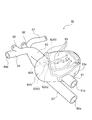
- FIG. 7 It is a figure which shows another example (3rd Embodiment) of the TAVI model which is one of the heart models based on this invention, (a) is a general view in the state equipped with an aortic valve, (b) is an aortic valve The partial view of the opening of the aorta and an aortic valve in the state which removed.
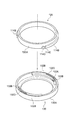
- (a) is an enlarged view of the removed aortic valve
- (b) is a perspective view looking at the inside of the TAVI model from the opening of the inflow tube, which is an enlarged view near the opening of the aorta.
- FIG. 18 is a perspective view of an extension member usable with the TAVI models of the second and third embodiments.
- BRIEF DESCRIPTION OF THE DRAWINGS The whole schematic which shows one use form of the container for catheter simulators which concerns on this invention.
- FIG. 1 is a view showing an embodiment of a catheter simulator container according to the present invention.
- the catheter simulator container will be described with reference to FIG.
- the catheter simulator container 10 of the present embodiment is configured as a container that defines a container 10 a for containing a liquid (not shown) such as water or electrolyzed water by the four side walls 11 to 14 and the bottom surface 15.
- a liquid such as water or electrolyzed water by the four side walls 11 to 14 and the bottom surface 15.
- a heart model four-chamber model in FIG. 3 (right heart model 20 in the present embodiment), a coronary artery model 30 in FIG. 4, and a TAVI model in FIG. 5) 40, connection portions 11a and 11c connectable to and held by the TAVI model 80 of FIG. 6 or the TAVI model 100 of FIG.
- introduction parts 11d, 12a, 13a for inserting a catheter
- discharge port 11b for discharging the liquid in the storage part 10a to a pulsatile flow generation pump 60 (see FIG. 12; hereinafter referred to as a pump)
- the connection portions 11 a and 11 c also serve as an introduction portion for inserting a catheter from the outside of the container 10.
- the side walls 11 to 14 and the bottom surface 15 are made of a material having a strength capable of stably containing a liquid and a heart model, and the shapes of the side walls 11 to 14 and the bottom surface 15 are short and round. It may be any shape as long as it can stably accommodate the liquid and the heart model, such as a shape having a combination of them.
- the materials of the side walls 11 to 14 and the bottom surface 15 preferably have transparency. The transparency of the side wall and the bottom makes it possible to visually observe the behavior of a heart model installed in the container 10 or a catheter inserted from the outside of the container 10 during simulation. Examples of the material having such strength and transparency are acrylic, polycarbonate, PET, polystyrene and the like.
- the behavior of the catheter can be displayed by installing a camera and displaying it on a monitor or displaying on a monitor etc. with X-ray fluoroscopy. It is possible to carry out simulations that are grasped only on the monitor, and it is also possible to realize a more realistic state. Visual recognition, monitor display confirmation, and use of X-ray imaging can be selected according to the stage and content of training.
- the upper part of the container 10 is open, and an openable and closable lid may be disposed there.
- an openable and closable lid may be disposed there.
- connection portions 11 a and 11 c are formed in a substantially cylindrical shape, penetrate through the side wall 11, and protrude toward the outside of the container 10.
- holding projections 11f and 11g that project to the container housing 10a side in the connection parts 11a and 11c, thereby inserting the end of the heart model and facilitating the heart model. It is possible to connect (hold).
- the supply pipe 63 (refer FIG. 12) of the pump 60 mentioned above is connected to the front-end
- connection portion 11a and the holding projection 11f are formed with communication holes through which the liquid fed from the pump 60 passes, and when the pump 60 is operated, also serve as a liquid inlet from the pump 60.
- connection portion 11c has a function as an introducing portion of the catheter
- connection portion 11c and the holding projection 11g are formed with communication holes through which the catheter is inserted.
- connection portion 11a and the discharge port 11b both have a valve 11V for opening / closing (only the connection portion 11a side is shown).
- the closing valve 11V prevents the liquid in the storage portion 10 a from leaking out of the container 10 by closing the valve 60 when removing the pump 60 from the container 10.
- connection portion 11c An introducing pipe 50 for introducing a catheter operated by a trainee from the outside of the container 10 is connected to the connection portion 11c. Further, the side wall 11 is provided with an introducing portion 11 d for connecting the catheter introducing tube 51.
- the connection portion 11 c and the introduction portion 11 d are formed in a substantially cylindrical shape, penetrate the side wall 11, and protrude outside the container 10.
- the connection portion 11 c and the introduction portion 11 d have a connection mechanism operable on the outside of the container 10.
- the connection mechanism has, for example, a structure capable of fixing and releasing the introduction pipes 50 and 51 when the introduction pipe is inserted and the operation member (nut) 19 is rotated, so that the detachment operation of the introduction pipe can be easily performed. It has become.
- connection portions 11a and 11c and the introduction portion 11d described above do not necessarily have to be disposed on the same side wall.
- An auxiliary plate 16 for reinforcing the strength of the side wall 11 may be adhered to the side wall 11. Reinforcement of strength by the auxiliary plate 16 can reduce the weight of the entire container 10 as compared to the case where the entire side wall 11 is thickened to increase the strength. If the visibility of the passing catheter or the like is reduced by bonding the auxiliary plate 16 to the side wall 11, the thickness of the side wall is increased by increasing only the side of the side wall 11 which needs to be strengthened. Also good. In addition, it is preferable to make the side wall into a flat plate having no unevenness, whereby the refraction of light is eliminated and the visibility inside is improved.
- the side wall 12 is provided with an introducing portion 12 a for connecting a catheter operated by a trainee with an introducing tube 52 for introducing a catheter from the outside of the container 10.
- An introduction portion 13a connected to the introduction pipe 53 is provided.
- These introduction parts 12a and 13a may be arranged on the same side wall.
- the container 10a is filled with a liquid such as water, and the heart model is suspended in the liquid.
- the floating state of the heart model allows the trainee to feel more realistic when operating the catheter. That is, by connecting (holding) the connection portions 11a and 11c provided on the side wall of the container, the cardiac model can be suspended in the liquid.
- a dedicated holder may be installed on the bottom surface of the container and the heart model may be supported from below and held in the liquid without providing a connection on the side wall.
- the element accommodated in the container 10 is only required to be a heart model of the same size as the human heart and a liquid for suspending it, so that the container 10 can be miniaturized.
- the external dimensions of the container 10 in this embodiment are about 20 cm ⁇ 20 cm ⁇ 15 cm, and the amount of liquid (water) that needs to be filled in the container is about 3 L to 6 L.
- the amount of water filled in the container 10a of the container is 6 L or less, even if it is a place where water service is not available, it is possible to carry out a simulation by transporting the water with a tank etc. Spreads.
- the weight of the water-filled container is so light that the trainee can handle it alone, so it is possible to prepare and clear up the simulation without the aid of the assistant.
- the trainee selects an introducing portion (connecting portion) for introducing a catheter from the introducing tubes 50 to 53 depending on the heart model to be used and the contents of simulation.
- the introduction tubes 50 to 53 have a catheter introduction terminal at the tip on the outer side of the container 10, and the introduction terminals have a function to prevent the liquid filled in the introduction tubes 50 to 53 from leaking to the outside (Valve function) and has a structure that allows the trainee to introduce and withdraw a catheter into the introduction tubes 50-53.
- the introduction tube 50 is formed in the coronary artery model 30 (FIG. 4), the TAVI model 40 (FIG. 5), 80 (FIG. 6) or 100 (FIG. 7) through the introduction portion 11c.
- the introductory tube 51 is connected to the inferior vena cava 22 formed in the right heart system model 20 (FIG. 3) through the introductory portion 11 d
- the introductory tube 52 is connected to the coronary artery model 30 through the introductory portion 12a.
- the introduction tube 53 is the superior vena cava 23, which is respectively formed in the right heart system model 20 and the TAVI model 40 through the introduction part 13a. 43 are connected respectively.
- the right heart system model 20 (one embodiment of the four-chamber model), which is one of the heart models according to the present invention, is installed in the storage portion 10a of the container 10.
- the aspect of the case will be described.
- a catheter is made to reach the inside of the heart, it is general to insert the catheter from the right ventricular system (right atrium, right ventricle) connected to a thick blood vessel (the vena cava) leading to the heart. Is formed for simulation of catheter examination inside the heart, surgery and the like.
- the right heart system model 20 of the present embodiment includes a main body 20A that imitates the heart of a human body, and the inside of the main body is the same as the human heart, the right atrium 20A1, the right ventricle 20A2, a left atrium (not shown), and a left ventricle 20A4 are formed.
- the right atrium 20A1 is connected with a vena cava (the lower vena cava 22, the superior vena cava 23), and the right ventricle 20A2 is connected with a pulmonary artery 24.
- the inferior vena cava 22 and the superior vena cava 23 are formed to be long enough to be connected to the catheter introducers 11d and 13a formed in the container 10, since they serve as a catheter introducer.
- the distal end portions of the inferior vena cava 22 and the superior vena cava 23 are open (openings 22a and 23a), and are respectively connected to the introducing portions 11d and 13a formed in the container 10 to introduce a catheter. It becomes a mouth.
- the inferior vena cava 22 leads to a femoral vein traveling in the inguinal region and serves as an introduction path for a catheter introduced from the inguinal region, and the superior vena cava 23 is introduced from an internal jugular vein traveling in the base of the neck It becomes an introduction path of a catheter.
- a blood vessel introducing a catheter is generally a femoral vein, and an internal jugular vein is selected according to a patient's condition etc. Because there are also, it is possible to select two introduction routes according to the actual situation.
- a support 21 connected to the container 10 is formed on the caudal side (end) of the main body 20A of the right heart model 20.
- the support portion 21 does not exist in the human body, in the present embodiment, as shown in FIG. 3, it has a shape in which two substantially rectangular parallelepipeds are connected. Recesses 21a and 21b formed at the end of the support portion 21 are connected to the holding projections 11f and 11g of the connection portions 11a and 11c of the container 10, so that the right heart model 20 can be stably used in the container 10 Have the function of fixing to Thus, the right heart system model 20 is held by the connection portions 11a and 11c so as to float in the liquid filled in the container portion 10a of the container.
- the recess 21a of the support portion 21 may not communicate with the inside of the main body 20A.
- the coronary artery model 30 in the present embodiment will be described.
- the coronary artery model 30 includes a main body 30A that simulates the heart of a human body.
- the heart of the human body comprises a right atrium, a right ventricle, a left atrium, and a left ventricle, but the main body 30A does not have such an internal structure, and the inside is hollow.
- an aorta 32 is provided on the head side of the main body 30A, like the heart of a human body.
- an inflow tube (end) 31 is provided at the apex of the heart formed on the caudal side of the main body 30A.
- the inflow pipe 31 is not present in the human body, but in the present embodiment, it is a path for flowing the liquid (pulsating flow) sent from the pump 60 (see FIG. 12) into the main body 30A.
- the liquid that has flowed into the main body 30A from the inflow pipe 31 passes through the interior of the cavity in a fixed direction, and reaches the aorta 32 with the same flow.
- a large number of coronary arteries 33 having a thin and complicated shape are formed on the surface of the main body 30A, like the human heart.
- the coronary artery 33 branches from the root of the aorta 32 and is provided along the surface of the main body 30A.
- a discharge port 33a is formed in the distal end region of the coronary artery 33, and the liquid flowing into the coronary artery 33 is discharged from the discharge port 33a to the outside (outside of the main body 30A).
- a simulation of a blood vessel connected to the aorta in a human body is provided on the path of the aorta 32 described above.
- a simulated blood vessel as shown in FIG. 4 specifically, a right subclavian artery 34, common carotid arteries 35 and 36 and a left subclavian artery 37 similar to the human body are provided.
- the right subclavian artery 34 is an introduction path of a catheter introduced from an arm, and a catheter operated by a trainee reaches the aorta 32 from the right subclavian artery 34 and further a coronary artery 33 branching from its root. Inserted into Further, in FIG.
- the aorta 32 extending to the back side of the main body 30A reaches the femoral artery traveling in the inguinal region, and serves as an introduction path of a catheter introduced from the inguinal region.
- the opening 31a of the inflow tube 31 is connected to the holding projection 11f of the connection portion 11a, and the opening 32a of the aorta 32 is connected to the holding projection 11g of the connection portion 11c. It is held to float. Then, in this state, the pulsating flow is inflowed from the external pump through the inflow pipe 31.
- the TAVI model 40 in the present embodiment includes a main body 40A that imitates the human heart, and the inside of the main body 40A is a right atrium 40A1, a right ventricle 40A2, a left atrium (not shown), a left ventricle 40A4 is formed. Similar to the heart of the human body, the right atrium 40A1 is connected with a vena cava (the lower vena cava 42 and the upper vena cava 43), the right ventricle 20A2 is connected with a pulmonary artery 44, and the left ventricle 40A2 is connected with an aorta 45. .
- the aorta may be equipped with the left subclavian artery 37 and the common carotid arteries 35 and 36 as in the coronary artery model 30 shown in FIG. Moreover, although the aortic valve is arrange
- the aorta 45, the inferior vena cava 42, the right subclavian artery 46, and the superior vena cava 43 serve as a catheter introducing path, and therefore, the connection portion 11c formed in the container 10 and the catheter introducing portions 11d, 12a, 13a.
- connection part 11c and the introduction parts 11d, 12a and 13a are connected to become an introduction port of a catheter.
- an inflow tube 41 is provided at the apex of the heart formed on the caudal side of the heart body.
- the fluid (pulsating flow) sent from the pump 60 (see FIG. 12) is made to flow into the main body in the same manner as the coronary artery model 30 described above. It becomes a route.
- the fluid that has flowed into the main body from the inflow tube 41 mainly flows from the left ventricle 40A4 to the aorta 45, partially from the coronary artery, and from the aorta to the common carotid artery, subclavian artery, and descending aorta.
- the coronary artery 33, the common carotid arteries 35 and 36, and the subclavian arteries 34 and 37 may be provided.
- the coronary artery branch (inlet) is located on the head side of the aortic valve.
- the aorta 45 and the inferior vena cava 42 respectively extend to the femoral artery and femoral vein which run in the inguinal region, and serve as a catheter introduction path introduced from the inguinal region.
- the superior vena cava 43 serves as an introduction path for a catheter introduced from an internal jugular vein that travels at the base of the neck.
- the catheter introduction site is generally the femoral artery or apex, but depending on the condition of the patient, the subclavian artery, As femoral veins and internal jugular veins may be selected, it is possible to add an introduction route according to the actual situation.
- the inflow tube 41 will be simultaneously used as a catheter insertion path as described in detail below, but at this time the catheter is inserted between the pump and the opening 41a.
- a catheter introducer may be newly provided or a bifurcated tube may be connected so that it can be performed.
- FIG. 6 is a view for explaining another embodiment of the TAVI model (TAVI model 80 which is the second embodiment).
- the TAVI model 80 is a cavity in which a right atrium, a right ventricle, a left atrium, and a left ventricle are not formed inside a main body 80A that simulates the heart of a human body.
- a main body 80A that simulates the heart of a human body.
- the catheter moves only inside the left ventricle to the aorta and is not a simulation moving inside the other right atrium, right ventricle, and left atrium
- the inside of the main body 80A is limited to these, namely, Even if the atrial septum, ventricular septum, tricuspid valve, and mitral valve are not formed, it does not become a major obstacle. It is possible to simulate the united cavity as the left ventricle.
- an aorta 82 is provided on the head side of the main body 80A.
- the aorta 82 projects from the head side of the main body 80A into the inside of the main body 80A, and an aortic valve 82A is formed at the tip end thereof like the human body.
- the aortic valve 82A is located at the boundary between the aorta 82 and the left ventricle in the human body, but in the present embodiment the left ventricle is not formed, so the aorta 82 is up to the position assumed when the left ventricle is present.
- the aortic valve 82A is formed at its tip.
- the aortic valve 82A has three leaflets, a right coronary apex 82A1, a left coronary apex 82A2, and a non-coronary apex 82A3, as in the human body.
- the aortic valve 82A has a shape in which the three valve leaflets are connected at the root like a petal, and each of the valve leaflets 82A1, 82A2, 82A3 has a rounded petal shape.
- three different color dots red, yellow, green
- each valve leaflet is associated with color one to one. It has become. These dots serve as marks for introducing and simulating a catheter under visual observation.
- radiopaque material for these points, it can be used as a so-called opaque marker under X-ray fluoroscopy as a mark at the time of simulation.
- shape of a marker should just be recognized as a mark, and is not limited to a point mark like a figure.
- the same process may be applied to the annulus part other than the bottom part of each valve leaflet to make a mark.
- an inflow tube (end portion) 81 is provided at the apex of the heart formed on the caudal side of the main body 80A.
- the inflow pipe 81 is not present in the human body, but in the present embodiment, it is a path for flowing the liquid (pulsating flow) sent from the pump 60 into the main body 80A.
- a coronary artery 83 is formed on the surface of the main body 80A, and simulation similar to that of the coronary artery model 30 described above can also be performed.
- the coronary artery 83 may not be formed because it is not essential for simulation of transcatheter aortic valve replacement using a TAVI model, but it is desirable that it be present.
- a coronary artery occlusion may occur as a complication, and in the operation, an angiogram of the coronary artery may be performed to confirm the occlusion state.
- a blood vessel mimic connected to the aorta in a human body is provided on the above-described path of the aorta 82.
- a simulated blood vessel as shown in FIG. 6, specifically, a right subclavian artery 84, common carotid arteries 85 and 86, and a left subclavian artery 87 similar to the human body are provided.
- an aorta 82 extending to the back side of the main body 80A extends to the femoral artery traveling in the inguinal region, and serves as an introduction path of a catheter introduced from the inguinal region.
- the opening 81a of the inflow tube 81 serves as an inlet for the pulsatile flow from the pump 60 as described above, and also serves as a catheter inlet in the apex approach.
- the indwelling stent valve is formed by making the diameter of the openings 41a and 81a of the inflow tube larger than that of the coronary artery model (opening 31a of the inflow tube of FIG. 4). It can be easily taken out from the apical side.
- FIGS. 7-8 are diagrams for explaining another embodiment of the TAVI model (the third embodiment, the TAVI model 100).
- the right atrium, the right ventricle, the left atrium, and the left ventricle are not formed inside the main body 100A that imitates the human heart, like the above-described TAVI model 80. , Is hollow.
- the inside of the main body 100A hollow there is an advantage that the pulsating flow flowing from the pump 60 makes the main body 100A easy to beat.
- the catheter moves only inside the left ventricle to the aorta and is not a simulation moving inside the other right atrium, right ventricle, and left atrium, the inside of the main body 100A is limited to these, ie, Even if the atrial septum, ventricular septum, tricuspid valve, and mitral valve are not formed, it does not become a major obstacle. It is possible to simulate the united cavity as the left ventricle.
- an aorta 102 is provided on the head side of the main body 100A.
- the aorta 102 protrudes from the head side of the main body 100A into the inside of the main body 100A, and the tip thereof is an opening 102b.
- the removable aortic valve 110 is attached to the opening 102b.
- the aortic valve 110 is located at the boundary between the aorta 102 and the left ventricle in the human body, but in the present embodiment the left ventricle is not formed, so the aorta 102 reaches the position assumed when the left ventricle is present.
- the aortic valve 110 is configured to be mounted at its tip.
- the aortic valve In the human body, the aortic valve is integrally connected to the tip of the aorta as in the TAVI model 80 of the second embodiment, but in the TAVI model 100 of the present embodiment, the aortic valve 110 is other than that And are separately formed and are detachable. For this reason, if the aortic valve 100 is prepared in accordance with various cases and patient-specific situations, simulations can be easily performed on various aortic valves by replacing only the aortic valve 100. Become. In the case of the TAVI model 80, it is necessary to form a plurality of whole TAVI models in accordance with the aortic valve, and in the case of installation, it is necessary to replace the whole model. Also, at the time of installation, only the aortic valve may be detached and replaced. It is efficient in many points such as manufacturing cost, work efficiency, storage space and so on.
- aortic valve 110 detachable, as will be described later, it becomes possible to easily remove the stained valve (a stent with a prosthetic valve) indwelling in the aortic valve 110 at the end of the simulation.
- the aorta 102 and the aortic valve 110 attached to and removed from the aorta will be described with reference to FIGS. 7 (b) to 9.
- the aortic valve 110 includes a valve leaflet 110A including respective leaflets of a right coronary leaflet 110A1, a left coronary leaflet 110A2 and a non-coronal leaflet 110A3 that simulate the aortic valve of a human body.
- the valve-shaped left ventricular outflow passage 112 is connected to the annular annulus 114 and the annulus 114 at the root of the valve leaflet 110A, where the valve leaflets are connected like a petal.
- the aortic valve 110 is inserted into the interior of the heart body 100A from the opening 101a of the inflow tube with the valve tip 110A forward, and is inserted into the opening 102b of the aorta. After insertion, the aortic valve 110 is fixed and attached to the tip of the aorta 102 by connecting the annulus 114 with the peripheral edge 102 c of the opening 102 b.
- the annulus portion 114 and the peripheral portion 102c of the opening 102b are connected by rotating and overlapping the projection 114B of the inner ring 120 and the projection 102B of the outer ring 130 bonded to each other.
- the structure is For this reason, at the time of insertion, it is necessary to insert so that the protrusion 114B on the annulus 114 side does not contact the protrusion 102B formed on the inner inner surface on the aorta 102 side.
- a mark black circle in the drawing
- the aortic valve 110 can be inserted in the correct orientation by inserting the protuberance 114B so that the protuberance 114B is not in contact.
- An inner ring 120 is fixed to the outer periphery of the valve ring portion 114, and an outer ring 130 is fixed to the inner inner peripheral surface of the peripheral portion 102c of the opening 102b of the aorta 102.
- the inner ring 120 is formed on an annular base 120A and an outer periphery of the base 120A, has a protrusion 114B substantially rectangular in cross section, and is adhered and fixed to the outside of the annulus 114 of the aortic valve 110.
- the protrusions 114B are formed at two locations facing each other at a lower part on the outer periphery of the mother body 120A with a central angle of about 80 °, and one end of the protrusions 114B is a periphery as shown in the figure. It has convex part 114D and concave part 114E which were continuously formed in the direction.
- the outer ring 130 has an annular base 130A and a protrusion 102B formed along the inner periphery of the base 130A and having a substantially rectangular cross section, and the inner side of the peripheral part 102c of the opening 102c of the aorta 102 It is fixed to the circumferential surface.
- the protrusions 102B are formed at two upper locations on the inner periphery of the mother body 130A with a central angle of about 90 ° and one of the end portions of the protrusions 102B is shown in the figure. Is provided with a convex portion 102E.
- the outer ring 130 forms a circumferential groove 102e on the inner peripheral surface of the peripheral portion 102c of the opening 102b of the aorta 102, and is embedded in the circumferential groove 102e.
- the outer ring 130 is formed of a hard resin (for example, an epoxy-based or urethane-based hard resin) harder than the material of the aorta 102.
- a stop tool 130B is formed on the inner peripheral surface of the base 130A of the outer ring at a position slightly away from the convex portion 102E in the circumferential direction, and the inner ring 120 is rotated by about 90 ° by this stop tool.
- the protrusion 114B is designed to stop at the position shown.
- the concave portion 114E at the tip of the projection 114 fits into the convex portion 102E of the projection 102B, and the convex portion 114D at the tip of the projection 114 corresponds to the convex portion 102E of the projection 102B and the stopper 130B. It is fixed in the gap of
- the stability of the attached aortic valve can be improved. It is preferable that the connection between the aortic valve 110 and the portion where the aorta 102 is engaged be stable because it is pushed by the catheter to be introduced or receives the pressure of the pulsatile flow from the pump.
- the inner part with respect to the valve ring part 114 so that the positions of the respective valve leaflets (right coronary leaflet 110A1, left coronary leaflet 110A2, non-coronary leaflet 110A3) become similar to the human body.
- the circumferential fixing position of the ring 120 and the circumferential fixing position of the outer ring 130 is design with respect to the inner peripheral surface of the peripheral portion 102c of the opening 102b of the aorta 102.
- the length in the circumferential direction of the protrusions 114B and 102B is a circumferential portion with a central angle of 80 to 90 °, and the number of the protrusions is two at each circumferential position.
- the structure is not particularly limited, and as described above, any structure may be used as long as the protrusion 102B and the protrusion 114B overlap when the aortic valve is attached.
- a slit 102D is provided in a part of the continuous portion of the projection 102B and the base 130A, whereby the projection 102E is formed when the projection 114D contacts the projection 102E (see FIG. 9). Slightly upward). Therefore, the convex portion 114D is configured to rotate even after coming into contact with the convex portion 102E, to displace the end of the protrusion 102B, and to reach the front stopper 130B. This makes it possible to give a sense of moderation at the time of wearing the aorta, and make it possible for the user to grasp the correct wearing position.
- the inner ring 120 or the outer ring 130 is preferably colored.
- a catheter can be introduced visually and can be used as an indication of the position when simulating stent valve placement.
- an X-ray opaque material is used for the colored portion, it becomes a mark when simulating as a so-called opaque marker even under X-ray fluoroscopy.
- a colored or radiopaque material may be used for the annulus portion 114 and the protrusion 114B of the aortic valve 110.
- the annulus of the patient is usually in a calcified condition and X-ray opaque, which is similar to the human body. It is possible to reproduce the situation of Furthermore, a material having radiopacity is applied to the surface of the valve leaflet 110A and the aorta 102, or the material forming the valve ring 110A is rendered radiopaque as in the human body. It is possible to reproduce the situation of calcification in the case of X-ray transmission to make the simulation closer to reality.
- a radiopaque material for example, a material containing hydroxyapatite, a calcium component or a metal component can be mentioned.
- FIG. 10 shows an embodiment in which a support portion (concave and convex that improves the frictional force on the surface) 116 is provided inside the aortic valve 110.
- a support portion concave and convex that improves the frictional force on the surface
- a large number of substantially triangular supports 116 are formed on the inner wall of the annulus 114 of the aortic valve 110 along the inner periphery of the annulus 114.
- the support portion 116 does not exist in the human body, it has an advantage of being able to securely fix and support a stent valve placed by catheter operation.
- the aortic valve of a patient who performs stent valve indwelling treatment has a rough surface due to calcification or the hardness of the valve itself is high, so the stent valve is easily fixed, but a simulation using a heart model In this case, since the surface of the aortic valve is smooth and the hardness of the valve itself is not so high, the deployed stent valve may slip and move along the pulsatile flow. Such a problem can be eliminated by forming the support portion 116 on the inner wall of the aortic valve 110 to improve the surface friction force more than that.
- an inflow tube (end) 101 is provided at the apex of the heart formed on the caudal side of the main body 100A.
- the inflow tube 101 is not present in the human body, but in the present embodiment, it is a path for flowing the liquid (pulsating flow) sent from the pump 60 into the main body 100A.
- the coronary artery 103 is formed on the surface of the main body 100A as in the case of the human heart, and it is also possible to perform the same simulation as the coronary artery model 30 described above.
- the coronary artery 103 may not be formed because it is not essential for simulation of transcatheter aortic valve replacement using a TAVI model, but it is desirable to have one.
- a coronary artery occlusion may occur as a complication, and in the operation, an angiogram of the coronary artery may be performed to confirm the occlusion state. Also, by inserting a guide wire into the coronary artery in advance, it is possible to cope with an occlusion.
- the inner diameter of the inflow tube 101 is preferably larger than the outer diameter of the aortic valve 110.
- the aortic valve 110 preferably has a size resembling a human body, and it is preferable that the aortic valve 110 be larger than the outer diameter of the aortic valve 110 by adjusting the inner diameter of the inflow tube 101.
- a simulation of a blood vessel connected to the aorta in a human body is provided on the path of the aorta 102 described above.
- a simulated blood vessel shown in FIG. 7A specifically, a right subclavian artery 104, common carotid arteries 105 and 106, and a left subclavian artery 107 similar to the human body are provided.
- the aorta 102 extending to the back side of the main body 100A reaches the femoral artery traveling along the inguinal region, and serves as an introduction path of a catheter introduced from the inguinal region.
- a catheter is introduced from the opening 101a of the inflow tube 101.
- the opening 101a serves as an inlet for the pulsatile flow from the pump 60 as described above, and also serves as a catheter inlet in the apex approach.
- the stent valve placed in the aortic valve is formed of a shape memory alloy, expanded at a temperature close to the body temperature (around 30 ° C. to 40 ° C.), and placed.
- a simulation similar to an actual operation is performed by adding a function (a heater or the like installed in the container 10) of a constant temperature bath capable of maintaining the temperature of the container 10 to the same level as human body temperature.
- a function a heater or the like installed in the container 10
- FIG. 11 is a perspective view of the extension member 140.
- the extension member 140 screw-engages with the tubular extension 144 and the extension 144, and the inflow of the holding projection 11f of the container 10 and the TAVI model 80 (100). It has a cylindrical base 142 connected to the tube 81 (101). As shown in the figure, the base portion 142 has irregularities on the outer peripheral surface, and is configured so as not to be easily detached when inserted into the inflow pipe 81 (101).
- An opening 142 c is formed in the inside of the base portion 142 and includes an inner wall having a screw groove formed therethrough.
- a thread is formed on one end 144b of the end of the extension portion 144, and the base portion 142 and the extension portion 144 are connected by rotationally fitting the thread with the thread groove of the opening 142c.
- a through opening 144c is formed in the inside of the extension part 144, and when the base material 142 and the extension part 144 are connected, the opening 144c and the opening 142c communicate with each other.
- the pump 60 is fed out from the pump 60 After passing through the opening 144c through the opening 142c, the pulsatile flow exits the other end 144a of the extension 144 and flows into the heart body 80A (100A) of the TAVI model 80 (100). That is, since the pulsating flow inlet in the heart main body 80A (100A) is moved from the root of the inflow tube 81 (101) to the end 144a by using the extension member 140, the aortic valve 82A (110) is further moved. Get closer to By moving the pulsating flow inlet flowing into the heart model closer to the aortic valve 82A (110), the pulsating flow can be concentrated on the aortic valve 82A (110) without being dissipated.
- the position of the end 144b in the opening 142c can be adjusted by screw fitting so that the position of the pulsating flow inlet (end 124b) flowing into the heart model can be varied. There is.
- the position of the end 124b can be adjusted according to the size of the TAVI model used for simulation, the pressure of the pulsatile flow, etc., and the concentration degree of the pulsatile flow to the aortic valve 82A (110) is optimized. it can.
- FIG. 12 is a view showing a mode of use of the catheter simulator container 10 provided with the bifurcated cock 70.
- a bifurcated tube (bifurcated cock 70)
- the connection portion 11a of the container 10 it is preferable to connect a bifurcated tube (bifurcated cock 70) to the connection portion 11a of the container 10.
- the inflow of the pulsatile flow and the introduction of the catheter can be realized by one opening 41a, 81a or 101a.
- the container 10 is connected to the pump 60 through the supply pipe 63 and the discharge pipe 61, and the bifurcated cock 70 is interposed between the supply pipe 63 and the connection portion 11 a of the container. There is.
- the container 10 may be installed on a fixing stand 200. Depending on the catheter, the guide wire, and other devices that are inserted, the container 10 may be moved by the pressure applied by the trainee at the time of the insertion, and such a situation can be prevented by fixing with the fixing base 200.
- the fixing table 200 may be made of a material (hardened urethane foam or the like) having sufficient strength for holding and fixing the container 10 and having resistance to the liquid to be filled in the container 10.
- the shape is not particularly limited as long as it has stability, but in the case of a plate as shown in FIG. 12, the container 10 can be installed by forming a recess on the plate surface.
- a fixing portion 91 may be formed on the fixing table 200 to hold and fix the introduction path of the catheter. This makes it easier for the trainee to apply pressure when inserting a catheter or the like.
- the heart model installed in the container 10 may be detached from the holding projections 11 f and 11 g of the container 10.
- the connection is reinforced by a fixing ring (not shown) or the heart model is fixed by a holding base (not shown). It can prevent the situation mentioned above.
- the main body 70A of the bifurcated cock 70 is disposed in the inflow tube 71 into which the liquid (pulsating flow) from the pump 60 flows, the introduction path 72 of the catheter, and the introduction path 72 of the catheter, and functions as a one-way valve.
- the inflow tube 71 is disposed to be orthogonal to the introduction path 72, and the opening 71 a of the inflow tube 71 communicates with the inside of the catheter introduction path 72 at the downstream side of the duckbill valve 74. There is. For this reason, the pulsating flow that has passed through the inflow pipe 71 flows into the introduction path 72 through the opening 71a.
- the inflow tube 71 may be disposed in the introduction passage 72 so as to communicate with the inside of the catheter introduction passage 72 on the downstream side of the duckbill valve 74, and is necessarily orthogonal to the introduction passage 72. It does not have to be arranged in
- the one end 72 a of the introduction path 72 is formed with a screw-shaped unevenness, and is connected to the connection portion 11 a of the container 10 by screwing. As a result, the liquid that has flowed into the introduction path 72 from the inflow pipe 71 flows into the TAVI model 40, 80 or 100 in the container 10 through the one end 72a.
- the duckbill valve 74 and the silicone rubber packing 76 are disposed between the end plate 78 and the location where the inflow pipe 71 is disposed orthogonal to the inside of the introduction passage 72.
- the duckbill valve 74 allows insertion of the catheter at the time of opening, and the silicone rubber packing 76 is formed with a hole 76a through which the catheter passes. These function as check valves to prevent the liquid flowing into the introduction path 72 from leaking out of the catheter introduction port 78a, and also play a role of permitting insertion and extraction of the catheter.
- the cross section of the duckbill valve 74 is a bird's beak, when a catheter having a substantially circular cross section is introduced, a gap is generated between the two. At this time, the liquid in the inflow tube 71 leaks from the duckbill valve 74 It will By preventing the leaked liquid from flowing out with the silicone rubber packing 76, the liquid flowing into the introduction path 72 can function as a check valve so as not to leak out from the catheter introduction port 78a.
- the catheter can be brought into close contact with the through hole 76a to eliminate the gap, and the duck bill valve The liquid leaked from 74 can be prevented from flowing out by the silicone rubber packing 76.
- the duckbill valve 74 is automatically closed by the fluid pressure in the catheter introducing passage 72, and the liquid in the catheter introducing tube 72 is shut off by the duckbill valve 74.
- the outflow of fluid from the catheter introducing port 78a to the outside is kept restricted.
- a lid or stopper may be attached to a portion of the catheter introduction port 78a as a mechanism for liquid outflow prevention.
- the bifurcated cock 70 when the insertion part of the catheter and the inlet from the pump 60 coincide, the insertion of the catheter into the heart model is permitted, and the liquid fed from the pump 60 is to the catheter insertion part side.
- Any structure may be used as long as it has a check valve structure that does not leak, and it is possible to appropriately deform, such as using a cross slit valve, for a valve body installed inside and a mechanism for preventing liquid leakage. .
- FIG. 14 shows an example in which a cross slit valve 94 is used for the bifurcated cock 90.
- the main body 90A of the bifurcated cock 90 is disposed in an inflow pipe 91 into which the liquid (pulsating flow) from the pump 60 flows, an introduction path 92 of a catheter, and an introduction path 92 of the catheter, and functions as a one-way valve.
- the inflow pipe 91 is disposed to be orthogonal to the introduction path 92, and the opening 91 a of the inflow pipe 91 communicates with the inside of the catheter introduction path 92 at the downstream side of the cross slit valve 94. ing. For this reason, the pulsating flow that has passed through the inflow pipe 91 flows into the introduction path 92 through the opening 91 a.
- the inflow tube 91 may be disposed in the introduction passage 92 so as to communicate with the inside of the catheter introduction passage 92 on the downstream side of the cross slit valve 94, and is necessarily orthogonal to the introduction passage 92. It does not have to be arranged as such.
- the introduction path 92 At one end 92 a of the introduction path 92, a screw-shaped unevenness is formed, and the connection portion 11 a of the container 10 is connected by screwing. As a result, the liquid that has flowed into the introduction path 92 from the inflow pipe 91 flows into the TAVI model 40, 80 or 100 in the container 10 through the one end 92a.
- a cross slit valve 94 and a valve unit 96 are disposed between the end plate 98 and the location where the inflow pipe 91 is disposed orthogonally.
- the valve unit 96 is internally provided with a slitted silicon plate 96A, and between the silicon plate 96A and the cross slit valve 94 and the end plate 98, as shown in FIG. 14, between the plastic spacer 96B and the plastic spacer 96B.
- a gel 96C is provided to increase the degree of adhesion.
- a hole for allowing insertion and removal of the catheter is formed in each component (silicon plate 96A, plastic spacer 96B, gel 96C) of the valve unit 96.
- the slitted silicon plate 96A has a two-piece structure (the shape of the slit is one each of a horizontal slit and a vertical slit), but the invention is not limited thereto. Several combinations are possible for the number of.
- the above-described heart model (right heart system model 20, coronary artery model 30, TAVI model 40, 80 or 100) is formed of a material having elasticity close to that of an actual human heart, and it is close to reality in simulation. The feel at the time of catheter operation can be obtained.
- the elastic heart body when the pulsatile flow is made to flow from the apex toward the aorta, the elastic heart body repeatedly expands and contracts. Like the heart, it is possible to pump blood (liquid).
- Materials having such elasticity include, for example, PVA (polyvinyl alcohol), polyurethane, epoxy resin, unsaturated polyester, phenol resin, silicon and similar materials, and other thermosetting resins and thermoplastic resins alone. Or what combined two or more etc. are mentioned. This makes it possible to train the catheter operation with a tentacle feel close to that of the human body.
- PVA polyvinyl alcohol
- polyurethane epoxy resin
- unsaturated polyester unsaturated polyester
- phenol resin phenol resin
- silicon and similar materials and other thermosetting resins and thermoplastic resins alone. Or what combined two or more etc. are mentioned. This makes it possible to train the catheter operation with a tentacle feel close to that of the human body.
- the trainee can insert a catheter or a guide wire by using a transparent or translucent material.
- the movement of other devices can be observed directly and visually, and furthermore, it becomes possible to visually recognize the behavior of the infusate injected from the catheter. That is, it is possible to simulate cardiac catheter test and treatment while linking the operation at hand and the movement of the catheter tip.
- the container 10 may be covered with a cover or the like so that the heart model can not be seen, or displayed on a monitor by X-ray fluoroscopy It is also possible to grasp the behavior of the catheter only on the monitor.
- each of the above-described heart models (right heart model 20, coronary artery model 30, TAVI model 40 or 80) be integrally manufactured without having an artificial joint. In this way, it is possible to prevent the occurrence of blood flow not seen in the human body by the joint, and also prevent the visual field from being blocked by the joint at the time of catheter insertion, and unnatural shading under fluoroscopy. Does not occur.
- the catheter simulator according to the present invention can be used as a preparation before actual catheter operation, such as selecting and examining a catheter and various devices that are most suitable for the patient before examination and surgery.
- a heart model is formed by the above-mentioned optical modeling method
- the surface of a heart model is not smooth, but a slight unevenness
- the visible light may be irregularly reflected on the uneven surface, which may lower the visibility.
- the irregular reflection can be reduced and the visibility can be improved by coating the same material on the surface after the formation of the cardiac model and smoothing the uneven surface.
- the TAVI model 100 has the removable aortic valve 110, the aortic valve 110 and the other parts are separately formed, but for the same reason as the other heart models described above, an artificial joint is made as much as possible. It is preferable not to have it but to form by the said optical modeling method, a coating method, etc.
- the inner ring 120 and the outer ring 130 shown in FIG. 9 are formed of epoxy resin, and the other portions are formed of silicon.
- the forming material of the inner ring 120 and the outer ring 130 is not limited to epoxy resin, and may be a material harder than the forming material (silicon in this embodiment) of the other parts of the heart model, such as urethane.
- the right heart system model 20 is installed in the storage portion 10a of the container 10 in a state where the container 10 is filled with a liquid as a preparation.
- the end portions 21a and 21b of the support portion are respectively connected and held in the liquid to the connection portions 11a and 11c of the container so that air does not enter the inside of the main body.
- the distal end portion 22a of the inferior vena cava 22 is connected to the introducing portion 11d of the container, and the distal end portion 23a of the superior vena cava 23 is connected to the introducing portion 13a of the container.
- a catheter is inserted from the internal jugular vein at the base of the neck, and a catheter is inserted from the femoral vein in the inguinal region.
- the catheter is introduced from the superior vena cava 23 through the introduction tube 53.
- the catheter introduced from the superior vena cava 23 enters the right atrium 20A1 and reaches the right ventricle 20A2.
- the catheter is introduced from the inferior vena cava 22 through the introduction tube 51.
- the catheter introduced from the inferior vena cava 22 enters the right atrium 20A1 and reaches the right ventricle 20A2.
- mapping for measuring an electrocardiogram by an electrode attached to the tip of the catheter and detecting a treatment area
- Pressure or cardiac output inside the heart such as a myocardial biopsy such as ablation of the diseased portion electrically ablated with electrodes at the tip of the catheter, myocardial biopsy in which the heart muscle of the suspected disease is picked and collected for pathological examination
- Perform catheter manipulation inside the heart such as right heart catheterization to measure volume.
- a pump 60 for generating a pulsatile flow is connected to the catheter simulation container 10 according to the present invention.
- the tip end of the connecting portion 11 a is obtained by projecting the supply pipe 63 of the pump 60 to the outside of the container 10 so that the flow of liquid supplied from the pump 60 flows in from the connecting portion 11 a of the container 10
- the discharge pipe 61 of the pump 60 is connected to the discharge port 11 b so that the liquid discharged from the container portion 10 a of the container to the pump 60 flows out from the discharge port 11 b to the external pump 60.
- the coronary artery model 30 is placed in the container portion 10a of the container in a state where the container 10 is filled with a liquid as a preparation.
- the inflow tube 31 of the coronary artery model 30 is connected to the holding projection 11 f of the connecting portion 11 a of the container in the liquid so that air does not enter the coronary artery model 30, and the opening of the tip of the aorta 32 32a is connected to the holding projection 11g of the connecting portion 11c of the container, and the opening 34a at the tip of the right subclavian artery 34 is connected to the introducing portion 12a of the container.
- the pump 60 connected to the coronary artery model 30 is intermittently driven to cause a pulsating flow in the liquid.
- the pump 60 has a function of receiving the liquid filled in the container 10 from the discharge port 11 b, delivering the liquid to the introduction pipe 31 at a predetermined pressure, and refluxing the liquid in the container 10.
- a circulation type pump which reciprocates a piston by a drive motor and sends out a liquid.
- the stroke of the piston that is reciprocated it is possible to change the amount of liquid (corresponding to blood pressure) to be delivered in one beat, and by changing the time of one reciprocation of the piston,
- the beat period of the model (corresponding to the heart rate) can be changed.
- a pressure of at most 300 mmHg 20 to 200 times a minute it becomes possible to generate a pulsating flow close to an actual human body. Similar pulsatile flow can also be generated with pumps of variable volume type, such as lobe pumps and tube pumps.
- the pressure for pumping out the liquid from the pump is preferably set to be at most 300 mmHg, because if it exceeds 300 mmHg, it will be different from the actual heart beat of the human body. That is, by adjusting in the range of 0 mmHg to 300 mmHg, it is possible to set a pulsation state according to each patient (each patient case).
- the heart rate When simulating the catheter operation to the actual heart, it is sufficient for the heart rate to be 20 to 200 bpm (beat per minute) in consideration of the beats of the human body that can be assumed, and in the actual heart surgery, the heart rate is 40 As it is considered that most of the operation is performed in the range of ⁇ 100 bpm, the capacity of the pump 60 may be any specification that can deliver 20 to 200 beats per minute to the heart model, taking into consideration the load of the pump In this case, effective simulation can be performed as long as at least 40 to 150 beats per minute can be sent to the heart model.
- the fluid flowing into the coronary artery 33 is discharged to the outside of the heart model 30 from an outlet 33 a provided at the tip of the coronary artery 33, and joins the fluid filled in the container 10.
- the fluid that has flowed into the aorta 32 is drained into the container 20 via the carotid arteries 35 and 36 and the left subclavian artery 37 which are blood vessels provided on the path of the aorta 32, and Join the filled liquid.
- a filter (not shown) for removing foreign matter at the outlet 11b.
- a catheter is inserted from the artery of the arm and a catheter is inserted from the artery of the inguinal region.
- the catheter is introduced from the right subclavian artery 34 via the introduction tube 52.
- the catheter introduced from the right subclavian artery 34 enters the carotid artery 35, passes through the carotid artery 35, and reaches the aorta 32.
- the catheter passes through the aorta 32 and is located at the inlet (corresponding to the coronary artery entrance) of the coronary artery 33 which branches near the junction with the main body 30A.
- the trainee grasps the entrance while visually observing the coronary artery 33 to be inserted (target for treatment) among the left and right coronary arteries, and performs an operation such that the catheter is engaged with the target coronary artery entrance. . That is, the trainee manipulates the catheter while visually observing the coronary artery in need of treatment for the thin and complex coronary artery 33 to engage with the entrance, and subsequently the guide wire required for the treatment is a target site.
- coronography angiography / coronoplasty such as dilation of blood vessel with a balloon catheter and placement of a stent (metal cylinder) .
- the catheter is introduced from the caudal tip (portion corresponding to the inguinal region) of the aorta 32 via the introduction tube 50.
- the catheter passes through the inside of the aorta 32 and reaches the introduction port of the coronary artery 33 provided in the vicinity of the connection between the aorta 32 and the main body 30A.
- the introduction path of the catheter is only on the path of the aorta 32, there are bifurcation points with the carotid arteries 35 and 36 and the right subclavian artery 37 on that path.
- Training can be performed to reach the inlet corresponding to the coronary artery entrance while confirming the positional relationship with the simulated blood vessel and the like.
- the trainee can perform catheterization and surgery training in the same manner as the blood vessels in the arm.
- the pump 60 is connected to the catheter simulation container 10 as in the case of using the coronary artery model 30 described above.
- the tip end of the connecting portion 11 a is obtained by projecting the supply pipe 63 of the pump 60 to the outside of the container 10 so that the flow of liquid supplied from the pump 60 flows in from the connecting portion 11 a of the container 10
- the discharge pipe 61 is connected to the discharge port 11 b so that the liquid discharged from the container portion 10 a of the container to the pump 60 flows out from the discharge port 11 b to the pump 60.
- the TAVI model 40 is installed in the container 10 a of the container in a state where the container 10 is filled with a liquid as a preparation.
- the inflow tube 41 of the TAVI model 40 is connected to the holding projection 11 f of the connection portion 11 a of the container in the liquid so that air does not enter the TAVI model 40 and the tip 45 a of the aorta 45 is
- the opening 42a at the tip of the inferior vena cava 42 is connected to the holding projection 11g of the connecting portion 11c of the container, and the opening 43a at the tip of the upper vena cava 43 is the introducing portion of the container Connect to 13a respectively.
- the pulsating flow flowing from the pump 60 makes it possible to pulse the heart in the same manner as an actual heart.
- the pump 60 is intermittently driven to cause pulsatile flow in the liquid according to the same specifications as in the case of connection with the coronary artery model 30 as described above.
- the fluid delivered from the pump 60 and flowing into the main body of the TAVI model 40 through the inflow tube 41 mainly flows from the left ventricle 40A4 into the aorta 45, partially into the coronary artery and the remainder from the aorta to the common carotid artery And flow to the subclavian artery, descending aorta.
- the drawing simply expresses only the skeletal part of the TAVI model, as shown in FIG. 4, the coronary artery 33, the common carotid arteries 35 and 36, and the subclavian arteries 34 and 37 may be provided.
- the operation training of the catheter is started with the simulated blood flow thus generated.
- simulation can be carried out in the case of insertion from the vein at the base of the neck, in the case of insertion from the apical region, in the case of insertion from the apical region, insertion from the artery and vein mainly in the inguinal region.
- an aortic valve for preventing backflow of blood flow is present, and the aortic valve hardens and the area through which blood can pass is narrowed aortic valve stenosis
- surgery TAVI or TAVR; transcatheter aortic valve replacement
- the folded artificial valve is made to reach the vicinity of the junction of the aorta 45 and the left ventricle 40A2 by a catheter, and then the artificial valve
- the catheter can be trained to expand and secure it in place.
- a catheter equipped with an artificial valve it is possible to expand the valve by operating only a balloon catheter and inflating the balloon at the aortic valve, that is, balloon aortic valvuloplasty (BAV). is there.
- BAV balloon aortic valvuloplasty
- the catheter When simulating an approach from the apex, the catheter is introduced into the left ventricle 40A via the inflow tube 41 and reaches near the aortic valve.
- the catheter When simulating an approach from the subclavian artery, the catheter is introduced into the aorta 45 via the right subclavian artery 46, reaches the vicinity of the aortic valve, and thereafter, almost the same as the approach from the inguinal artery It is possible to carry out a simulation on the flow.
- the catheter when the trainee simulates catheter insertion from the vein at the base of the neck, the catheter is introduced from the superior vena cava 43 through the introduction tube 53 and reaches the right atrium 40A1.
- the catheter when a catheter is introduced from a vein in the inguinal region, the catheter is introduced from the inferior vena cava 42 through the introduction tube 51 and reaches the right atrium 40A1.
- the catheter that has reached the right atrium 40A1 then passes inside the right atrium and enters the right ventricle 40A2 formed ahead of the right atrium 40A1.
- the boundary between the right atrium 40A1 and the right ventricle 40A2 is provided with a tricuspid valve (not shown) for preventing blood regurgitation like the human body.
- the catheter passes through the right ventricle 40A2, it reaches the pulmonary artery 44.
- the boundary between the right ventricle 40A2 and the pulmonary artery 44 is provided with a pulmonary valve (not shown) for preventing blood backflow as in the human body.
- the trainee can simulate the same catheter treatment as that of the aortic valve described above for these tricuspid valve and pulmonary valve.
- the TAVI in the container portion 10a of the container is filled with liquid as a preparation in advance. Install the model 80.
- the inflow tube 81 of the TAVI model 80 is connected to the holding projection 11 f of the connecting portion 11 a of the container in the liquid so that air does not enter the TAVI model 80 and the distal end 82 a of the aorta 82 is It is connected to the holding projection 11g of the connection portion 11c of the container.
- the TAVI model 80 is installed after the base 142 of the extension member is connected to the holding projection 11 f.
- the inflow pipe 81 is connected to the base 142.
- the fluid that is pumped from the pump 60 and flows into the main body of the TAVI model 80 through the inflow pipe 81 passes from the heart body 80A through the aortic valve 82A and flows into the aorta 82.
- a portion of the fluid flowing into the aorta 82 flows into the coronary artery 83, and is discharged from the outlet port 83a provided at the tip of the coronary artery 83 to the outside of the TAVI model 80 to fill the container 10 with the fluid. Join together.
- the fluid flowing along the aorta 82 is discharged into the vessel 10 through the carotid arteries 85 and 86 and the subclavian arteries 84 and 87 which are blood vessels provided on the path of the aorta 82, and the vessel Join the liquid filled in 10.
- the liquid discharged from the tip openings of the coronary artery 83, the carotid arteries 85 and 86, and the subclavian arteries 84 and 87 into the container 10 flows out from the discharge port 11b and circulates to the pump.
- the operation training of the catheter is started with the simulated blood flow thus generated.
- simulation in the case of inserting from the apex can be implemented.
- the inguinal arterial approach requires less strain on the patient's body, but because the route to reach the heart is long, the tortoise of the blood vessel is complicated, or the catheter is used when calcification is seen in the blood vessel Not suitable as an introduction route for In that case, an apical approach in which the heart is pierced with a needle and the catheter introducing port is opened is a powerful means.
- a catheter When a catheter is introduced from the artery in the inguinal region, the catheter is inserted into the caudal tip of the aorta 82 through the introduction tube 50, and then travels on the path of the aorta 82 toward the heart body, and the aortic valve 82A Reach near.
- Surgery (TAVI or TAVR; transcatheter aortic valve replacement) is performed to replace the aortic valve with a prosthetic valve as a treatment for aortic valve stenosis or the like in which the aortic valve hardens and the area through which blood can pass is narrowed.
- the point mark drawn on the bottom of the three valve leaflets of the aortic valve 85A described above can be used as an indication of the position at which the artificial valve is expanded or the balloon is expanded. It is an effective aid for beginners.
- a radiopaque material for these points to make a mark for simulating as a so-called opaque marker even under fluoroscopy.
- injecting a contrast agent the positional relationship between the aortic valve 85A and the catheter is grasped, and the position at which the artificial valve is expanded or the balloon is inflated is confirmed.
- the catheter is introduced to the heart body 80A via the inflow tube 81 and reaches near the aortic valve 82A. From then on, it is possible to simulate in the same flow as the approach from the inguinal artery. In this case, a catheter is introduced from the inflow tube 81 while maintaining the inflow of the pulsatile flow from the inflow tube 81 by the bifurcated cock 70 described above.
- the pump 60 is connected to the catheter simulation container 10, and then the container 10 is filled with the liquid as a preparatory preparation. , Install the TAVI model 100.
- the inflow tube 101 of the TAVI model 100 is connected to the holding projection 11 f of the connecting portion 11 a of the container in liquid so that air does not enter the TAVI model 100 and the leg side of the aorta 102
- the tip end portion 102a is connected to the holding projection 11g of the connection portion 11c of the container.
- the aortic valve 110 is attached to the TAVI model 100 before the installation of the container, the simulation is continuously performed, and when the aortic valve 110 is repeatedly attached and detached, the state where the TAVI model 100 is installed
- the inflow tube 101 is removed from the holding projection 11 f (the base 142 when the extension member 140 is used), and only the aortic valve 110 is opened from the opening 101 a of the inflow tube 101 (in the case where a stent valve indwelling is included).
- the aortic valve 110 may be inserted and inserted through the opening 101a as follows.
- the aortic valve 110 enters the interior of the heart body 100A through the opening 101a of the inflow tube with the valve tip 110A forward with the left ventricular outflow channel 112 held by the user, Is inserted into the opening 102b of After insertion, the aortic valve 110 is fixed and attached to the tip of the aorta 102 by connecting the annulus 114 with the peripheral edge 102 c of the opening 102 b.
- the fixing method is as described above.
- the pulsating flow flowing from the pump 60 makes it possible to pulse the heart in the same manner as an actual heart.
- the pump 60 is intermittently driven to generate a pulsatile flow in the liquid according to the same specification as in the case of connection with the coronary artery model 30, the TAVI model 40 or 80, as described above.
- the fluid that is pumped from the pump 60 and flows into the main body of the TAVI model 100 through the inflow tube 101 passes from the heart body 100A through the aortic valve 110 and flows into the aorta 102.
- the aortic valve 110 is removable but fixed so as not to be desorbed by the flow of fluid from the pump.
- a part of the fluid flowing into the aorta 102 flows into the coronary artery 103, and is discharged from the discharge port 103a provided at the tip of the coronary artery 103 to the outside of the TAVI model 100 and filled in the container 10 Join together.
- the fluid flowing along the aorta 102 is discharged into the vessel 10 through the carotid arteries 105 and 106 and the subclavian arteries 104 and 107 which are blood vessels provided on the path of the aorta 102, and the vessel Join the liquid filled in 10.
- the liquid discharged from the tip openings of the coronary artery 103, the carotid arteries 105 and 106, and the subclavian arteries 104 and 107 into the container 10 flows out from the discharge port 11b and circulates to the pump.
- the operation training of the catheter is started with the simulated blood flow thus generated.
- simulation in the case of inserting from the apex can be implemented.
- the inguinal arterial approach requires less strain on the patient's body, but because the route to reach the heart is long, the tortoise of the blood vessel is complicated, or the catheter is used when calcification is seen in the blood vessel Not suitable as an introduction route for In that case, an apical approach in which the heart is pierced with a needle and the catheter introducing port is opened is a powerful means.
- the catheter When a catheter is introduced from an artery in the inguinal region, the catheter is inserted into the distal end 102b of the aorta 102 through the introduction tube 50, and then travels on the path of the aorta 102 toward the heart body, and the aortic valve 110A Reach near. After reaching the vicinity of the aortic valve 110A, operations of TAVI and BAV can be simulated similarly to the simulation of the TAVI model 80 described above.
- the catheter in the case of simulating an approach from the apex, the catheter is introduced into the heart body 100A via the inflow tube 101 and reaches near the aortic valve 110A. From then on, it is possible to simulate in the same flow as the approach from the inguinal artery. In this case, a catheter is introduced from the inflow tube 101 while maintaining the inflow of the pulsatile flow from the inflow tube 101 by the bifurcated cock 70 described above.
- the artificial valve is expanded or the balloon is expanded by the mark of the aortic valve 110 (mark of the valve annulus) as in the mark of the aortic valve 82A in the TAVI model 80 (point mark of the valve leaflet).
- the positional relationship between the aortic valve 110 and the catheter can be grasped by using a position indicator or injecting a contrast agent.
- the aortic valve 110 in which a stent valve (not shown) is placed can be removed from the TAVI model 100, and the stent valve can be removed from the aortic valve at hand.
- a hand is inserted from the opening 101a of the inflow tube 101, and the left chamber outflow passage portion 112 is held and rotated to release the fitting, and then return inside the inflow tube 101 again. Take it out. Similar work may be performed with forceps, scissors, clips or the like instead of hands.
- connection and use of an external pulsatile flow generation pump can be selected according to the heart model connected to the container, various heart models can be switched, and the use of an external pump can also be selected. It is configured to be able to. This makes it possible to flow a pulsatile flow into the heart model and perform simulation under a realistic heartbeat, for a catheter procedure that is greatly affected by the heartbeat.
- the container 10 can hold the heart model in a floating state by the connection portions 11a and 11c provided on the side wall of the container 10, it is possible to reduce the size and weight without requiring any other dedicated holder or the like. . This expands the choice of where to run the simulation, and also allows the trainee to prepare and clear the simulation alone without the constraints of an assistant.
- the catheter technique such as treatment of coronary artery on the surface of the heart, coronary angiography, coronary angioplasty
- mapping for diseases inside the heart, ablation treatment, catheter operations such as tissue sampling for myocardial biopsy, transcatheter aortic valve replacement, etc.
- the pulsating flow flowing into the heart model makes the pulsating close to reality. Simulation can be performed.
- the various heart models described above can be created based on CT images of actual patients or based on individual cases, it is possible to perform preoperative simulation for each case.
- the heart model can be easily replaced, it is possible to provide an environment for training as a general-purpose model for practice to beginners such as medical students and trainees, but it is also difficult for skilled persons It can be used for training of high cases. That is, based on heart CT data captured in advance, it is possible to model a heart model and simulate it before actual surgery.
- the container for catheter simulators concerning this invention and an example of the embodiment of the various heart models accommodated in the said container were shown, this invention is not limited to said embodiment, This invention Various changes can be made without departing from the scope of the present invention.
- the shape of the container or the bifurcated cock, and the arrangement position of the connection portion and the introduction portion can be appropriately modified.
Landscapes
- Engineering & Computer Science (AREA)
- Physics & Mathematics (AREA)
- General Physics & Mathematics (AREA)
- Health & Medical Sciences (AREA)
- General Health & Medical Sciences (AREA)
- Medical Informatics (AREA)
- Educational Technology (AREA)
- Pure & Applied Mathematics (AREA)
- Computational Mathematics (AREA)
- Medicinal Chemistry (AREA)
- Mathematical Analysis (AREA)
- Mathematical Optimization (AREA)
- Mathematical Physics (AREA)
- Algebra (AREA)
- Business, Economics & Management (AREA)
- Educational Administration (AREA)
- Chemical & Material Sciences (AREA)
- Theoretical Computer Science (AREA)
- Nuclear Medicine, Radiotherapy & Molecular Imaging (AREA)
- Life Sciences & Earth Sciences (AREA)
- Surgery (AREA)
- Radiology & Medical Imaging (AREA)
- Oral & Maxillofacial Surgery (AREA)
- Biomedical Technology (AREA)
- Heart & Thoracic Surgery (AREA)
- Molecular Biology (AREA)
- Animal Behavior & Ethology (AREA)
- Public Health (AREA)
- Veterinary Medicine (AREA)
- Pathology (AREA)
- Instructional Devices (AREA)
- Apparatus For Radiation Diagnosis (AREA)
- External Artificial Organs (AREA)
Abstract
カテーテル・シミュレーター用容器10は、側壁11~14と底面15によって液体を収容する収容部10aを規定する。側壁には、収容部10aに液体を満たした状態で設置される四腔型モデル、冠動脈モデル、TAVIモデルのいずれかの心臓モデルであっても保持可能な接続部11a、11cと、前記心臓モデルに一体形成された模擬血管に対して、前記容器の外部からカテーテルを挿入するための導入部11d、12a、13aとが形成されている。
Description
本発明は、カテーテル・シミュレーター用容器、及びこの容器内に収容される心臓モデルに関する。
従来、医療現場では、心臓等の臓器の検査や治療を行う目的で、腕や足の動脈からカテーテルを挿入し臓器に到達させる方法が用いられている。このカテーテル手技に関しては、操作技術の習得や上達を図るために、種々のシミュレーターが提案されており、コンピュータ・シミュレーターによる訓練に加えて、近年は、実際のカテーテル操作の感触により近い訓練が実現できるシミュレーターが発案されている。
例えば、特許文献1では、生体器官と同程度の弾性等を有する模擬臓器および模擬血管を用いて、模擬血液(液体)を循環させるトレーニング装置(シミュレーター)を開示している。このシミュレーターは、液体を循環させることで、訓練に伴う準備や後始末にかかる手間を減らすと共に、X線撮像に基づくカテーテル操作の訓練を実施可能としている。さらに、心臓モデル(模擬心臓)を拍動(周期的な収縮運動)させることで、拍動した状態における冠動脈に対するカテーテル手技を訓練することができ、より現実に近い訓練を実施可能としている。
また本発明者らは、先の特許出願(特許文献2)において、より現実に近い訓練を、より簡便な構成で実現するカテーテル・シミュレーターを提案している。先の特許出願に係るカテーテル・シミュレーターは、冠動脈に生じる不自然な模擬血液(液体)の流れを抑制すると共に、心臓モデルを拍動させるための必要部品(電磁弁、圧力センサ、電磁弁コントローラー等)を極力減らし、X線撮像システムを必須としない構成(目視による訓練も実施可能)となっている。
上記した特許文献1に開示されたカテーテル・シミュレーターでは、冠動脈に対して大動脈側から液体(模擬血液)を供給する構造となっているため、実際の心臓部分の血流とは異なる状況となってしまう。この結果、人体と同様の冠動脈内血流、およびその血流速度の実現が難しくなり、実際に行われる冠動脈カテーテル検査・手術と同じ状況下で訓練することができない。また、心臓の本体に供給管と排出管を接続して、本体内で液体を循環させており、更には、冠動脈からも液体を本体内に供給する構造となっているため、本体内で不自然な流れが生じたり、冠動脈に逆戻りする流れが発生したりしてしまう。このため、冠動脈にカテーテルを挿入する際に、実際の人体では見られない不自然な流れに対処する必要が生じる。
また従来技術では、心臓モデルを拍動させるために、心臓モデルに流入する液体の供給量を周期的に変動させている。この供給量を制御するために電磁弁、圧力センサ、電磁弁コントローラー等の部品を用いており、シミュレーターの構造が複雑になるという問題がある。
上記した従来技術の問題は、先の特許出願(特許文献2)で提案した発明によって解決することができるものの、先に提案したカテーテル・シミュレーターでは、拍動流を生成するポンプが必要とされ、容器内に設置される心臓モデルについても、冠動脈に対する技術の向上を意図したものとなっており、改良すべき余地がある。
すなわち、心臓に対するカテーテル操作は、心臓表面の冠動脈以外にも、心臓の内部に対して行うことがあり、このような複数パターンのカテーテル手技についても、より簡便に訓練できるようにすれば、医師の技術の向上に役立つものと考えられる。具体的には、検査や手術の態様に応じた心臓モデルを準備しておき、各心臓モデルを最適な状態にセットしてカテーテル手技が訓練できれば、様々なタイプの心臓疾患に応じて、効果的に使用者の技量を向上することが可能である。
本発明は、上記した実情に着目してなされたものであり、様々なカテーテル操作訓練を簡便に行うことを可能にするカテーテル・シミュレーター用容器を提供することを目的とする。また、本発明は、そのようなカテーテル・シミュレーター用容器に設置され、各種カテーテル手技をシミュレーションすることが可能な心臓モデルを提供することを目的とする。
上記した目的を達成するために、本発明は、側壁と底面によって液体を収容する収容部を規定するカテーテル・シミュレーター用容器であって、前記収容部に液体を満たした状態で設置される四腔型モデル、冠動脈モデル、TAVIモデルのいずれかの心臓モデルであっても保持可能な接続部と、前記心臓モデルに一体形成された模擬血管に対して、前記容器の外部からカテーテルを挿入するための複数の導入部とが形成されていることを特徴とする。
上記したカテーテル・シミュレーター用容器には、心臓モデルを保持する接続部が設けられている。前記各心臓モデルには前記容器の接続部と接続する端部が形成されており、前記端部が、前記容器の接続部に接合されると、前記心臓モデルは液体が満たされた前記容器に浮遊した状態で保持される。なお、ここでの「端部」とは、心臓モデルの本体の外側に、容器に対して接続するための用途として、予め心臓の本体に一体形成される部分であり、実際の人体の心臓には存在しない要素である。
前記心臓モデルの端部を前記容器の接続部に対して脱着すると、同一の容器を使用したまま、各種心臓モデル(四腔型モデル、冠動脈モデル、TAVI(Transcatheter Aortic Valve Implantation;経カテーテル的大動脈弁置換術)モデル)を切替えてシミュレーション可能となる。
例えば、冠動脈モデルを前記容器に接続して、前記容器内に充填された液体中に浮遊される状態で設置し、冠動脈造影のカテーテル手技を訓練後、前記容器内から前記冠動脈モデルを取外し、次にTAVIモデルを前記容器に接続して、前記液体内に浮遊状態で設置すると、前記液体が充填された同一の容器を使用したままの状態で、連続的に、経カテーテル的大動脈弁置換術のシミュレーションが実施できる。このように、本発明に係るカテーテル・シミュレーション用容器を用いると、目的のシミュレーションに応じて各種心臓モデルを切替えることによって、簡便に、様々な心臓カテーテル操作訓練を連続的に行えるようになる。
例えば、冠動脈モデルを前記容器に接続して、前記容器内に充填された液体中に浮遊される状態で設置し、冠動脈造影のカテーテル手技を訓練後、前記容器内から前記冠動脈モデルを取外し、次にTAVIモデルを前記容器に接続して、前記液体内に浮遊状態で設置すると、前記液体が充填された同一の容器を使用したままの状態で、連続的に、経カテーテル的大動脈弁置換術のシミュレーションが実施できる。このように、本発明に係るカテーテル・シミュレーション用容器を用いると、目的のシミュレーションに応じて各種心臓モデルを切替えることによって、簡便に、様々な心臓カテーテル操作訓練を連続的に行えるようになる。
上記した心臓モデルは、人体の心臓に近い弾力性を有する材料で形成されており、トレーニング者は、シミュレーションの目的に応じて、四腔型モデル、冠動脈モデル、TAVIモデルのいずれか一つを選択的に使用する。前記冠動脈モデル、前記TAVIモデルを用いる場合には、拍動流を生成するポンプを前記容器の外部から接続し、これらの心臓モデルに拍動流を流入させることが好ましい。これらの心臓モデルを用いてシミュレーションする冠動脈造影や経カテーテル的大動脈弁置換術等は、一般的に、カテーテル操作時に拍動の影響を大きく受ける。このため、前記冠動脈モデル、前記TAVIモデルにおいて人体の心臓と同様な拍動を模擬し、トレーニング者に対して、より現実に近い状況を提供することが望ましい。
一方、前記四腔型モデルを使用する場合には、前記外部ポンプを接続しなくてもよい。前記四腔型モデルを用いてシミュレーションする検査や手術は、主に不整脈に対するアブレーションや、心筋生検、右心カテーテル検査であって、一般的に、カテーテル操作時に拍動の影響をあまり考慮する必要がないためである。すなわち、本発明に係るカテーテル・シミュレーション容器と前記四腔型モデルを用いると、前記外部ポンプを接続しない状態であっても、前記四腔型モデルを用いたシミュレーションが実施可能となる。この場合、前記ポンプや前記ポンプの作動に必要な電力供給等に制約されずに訓練を実施することができる。
ただし、トレーニング者の選択によっては、前記四腔型モデルの使用下であっても、前記ポンプを前記容器に接続した状態でシミュレーションすることも可能である。例えば、上述したように、前記冠動脈モデルの使用後に、前記四腔型モデルを連続的にシミュレーションする場合、これらの心臓モデルを切替える際に前記ポンプの脱着を行わず、そのままシミュレーションを継続することもできる。すなわち、前記ポンプの使用は、シミュレーションの種類や内容、順番等に応じて、トレーニング者が自在に選択することができる。このように本発明に係るカテーテル・シミュレーション用容器は、各種心臓モデルを切替られると共に、必要に応じてポンプの使用も選択できるように構成されている。
上記したカテーテル・シミュレーション用容器には、その容器専用に製造された心臓モデル(四腔型モデル、冠動脈モデル、TAVIモデル)が設置される。
本発明に係る心臓モデルの一つである四腔型モデルは、心臓本体と、前記心臓本体に繋がる大静脈(上大静脈、下大静脈)と、前記容器の接続部と接続可能な端部(サポート部)とを有し、これら各部は一体的に形成されている。前記心臓本体の内部には、人体の心臓と同様、右心房、右心室、左心房、左心室等が形成されている。この四腔型モデルは、前記心臓本体の表面に人体の心臓に存在する冠動脈は備えていなくても良い。
本発明に係る心臓モデルの一つである四腔型モデルは、心臓本体と、前記心臓本体に繋がる大静脈(上大静脈、下大静脈)と、前記容器の接続部と接続可能な端部(サポート部)とを有し、これら各部は一体的に形成されている。前記心臓本体の内部には、人体の心臓と同様、右心房、右心室、左心房、左心室等が形成されている。この四腔型モデルは、前記心臓本体の表面に人体の心臓に存在する冠動脈は備えていなくても良い。
前記四腔型モデルを用いると、心臓内部に対するカテーテル手技、例えば、心臓内部の電気的異常部位を検出するためのマッピング等の電気生理学的検査、前記異常部位を焼灼するためのアブレーション治療、病気が疑われる部分の組織を病理検査目的で採取する心筋生検、心臓内部の圧力や心拍出量を測定するための右心カテーテル検査等に関するカテーテル・シミュレーションが実施できる。
本発明に係る心臓モデルの一つである冠動脈モデルは、心臓本体と、前記心臓本体の表面の冠動脈と、前記心臓本体の頭側と繋がる大動脈と、前記心臓本体の心尖部(心臓本体の尾側)に設けられた端部(流入管)とを有し、これらは一体的に形成されている。前記流入管の先端は開口しており、前記容器の接続部に接続されると共に、前記ポンプから送り出される拍動流を前記心臓本体に流入させる経路となる。前記心臓本体の内部は空洞であり、前記心臓本体の表面には、人体の心臓と同様に、冠動脈が形成されている。前記ポンプから供給された拍動流は、前記流入管から前記心臓本体に流入し、空洞である前記心臓本体内部を通過して、一部が前記冠動脈に流入し、残りの部分は前記大動脈に到達する。
このようにして前記心臓本体の内部及び前記冠動脈には、前記拍動流が流入し、人体の心臓と同様な鼓動によって液体が供給されると、拍動下の冠動脈に対するカテーテル手技、例えば、冠動脈造影、冠動脈形成術等に関するシミュレーションが実施可能となる。
前記TAVIモデルは、心臓本体と、前記心臓本体の頭側と繋がる大動脈と、前記心臓本体の心尖部(心臓本体の尾側)に設けられた端部(流入管)とを有し、これらは一体的に形成されている。前記心臓本体の内部には、人体の心臓と同様、右心房、右心室、左心房、左心室等が形成されている。上記した冠動脈モデル同様に、前記流入管の先端は開口しており、前記容器の接続部に接続されると共に、前記ポンプから送り出される拍動流を前記心臓本体に流入させる経路となる。前記心臓本体の内部には、前記拍動流が流入し、人体の心臓と同様な鼓動によって液体が供給される。このようにして前記ポンプから前記TAVIモデルに拍動流が供給されると、拍動下の心臓内部に対するカテーテル治療(経カテーテル的大動脈弁置換術等)が行えるようになる。
前記TAVIモデルは、前記右心房、右心室、左心房、左心室が形成されておらず、心臓本体の内部は空洞であっても良い。心臓本体の頭側と繋がる大動脈が、人体同様に、心臓本体の内部に突き出ており、その先端に大動脈弁が形成されていれば、TAVIモデルのシミュレーション対象とする経カテーテル的大動脈弁置換術が実施できる。
本発明のカテーテル・シミュレーター用容器及び前記容器に設置される各種心臓モデルによれば、検査や手術の態様に応じた複数パターンのカテーテル手技をより簡便に実施可能となる。
以下、図面を参照して本発明の実施形態について説明する。
図1は、本発明に係るカテーテル・シミュレーター用容器の一実施形態を示す図である。最初に、図1を参照して、カテーテル・シミュレーター用容器について説明する。
図1は、本発明に係るカテーテル・シミュレーター用容器の一実施形態を示す図である。最初に、図1を参照して、カテーテル・シミュレーター用容器について説明する。
本実施形態のカテーテル・シミュレーター用容器10は、四面の側壁11~14及び底面15によって水、電解水などの液体(図示せず)を収容する収容部10aを規定する容器として構成される。前記側壁には、前記収容部10aに液体を満たした状態で心臓モデル(図3の四腔型モデル(本実施形態における右心系モデル20)、図4の冠動脈モデル30、図5のTAVIモデル40、図6のTAVIモデル80又は図7のTAVIモデル100)を接続して保持可能な接続部11a、11cと、前記心臓モデルに一体形成された模擬血管に対して、前記容器10の外部からカテーテルを挿入する導入部11d、12a、13aと、前記収容部10a内の液体を拍動流生成ポンプ60(図12参照;以下ポンプと称する)に排出する排出口11bが形成されており、例えば図1に示すような位置関係で配設される。なお、前記接続部11a、11cは、前記容器10の外部からカテーテルを挿入する導入部の役割も兼ねる。
前記側壁11~14及び前記底面15は、液体及び心臓モデルを安定的に収容可能な強度を有する材料によって作製されており、前記側壁11~14及び前記底面15の形状は、短形形状、丸みを帯びた形状、それらを組合せた形状等、前記液体及び前記心臓モデルを安定的に収容できる形状であれば良い。また、前記側壁11~14及び前記底面15の材料は透明性を有することが好ましい。側壁や底面が透明性を有することで、シミュレーションの際、前記容器10内に設置された心臓モデルや、前記容器10の外部から挿入するカテーテル等の挙動を目視によって観察することが可能となる。このような強度を有し、透明性のある材料は、例えばアクリル、ポリカーボネート、PET、ポリスチレン等が挙げられる。
なお、トレーニング者が視認できる材料で前記容器10を作製した場合でも、カメラを設置してモニタ等に表示したり、或いは、X線による透視をしてモニタ等に表示すれば、カテーテルの挙動をモニタ上のみで把握するシミュレーションを実施でき、より現実に近い状態を実現することも可能である。訓練の段階や内容に応じて、目視認識、モニタ表示確認、X線撮像の使用を選択できる。
前記容器10の上方は、開口しており、ここに開閉可能な蓋を配設しても良い。これにより、収容部10aに液体を充填する作業、心臓モデルを液体内に設置する作業等、訓練の準備や後始末をする際に、容器上面の開口を介して効率的に作業することができる。
本実施形態において、前記接続部11a、11cは略円筒状に構成され、前記側壁11を貫通し、前記容器10の外部に向けて、それぞれ突出している。この場合、前記接続部11a、11cには、前記容器収容部10a側に突出する保持突起11f、11gを形成しておくことが好ましく、これにより、心臓モデルの端部を差し込んで心臓モデルを容易に接続(保持)することが可能となる。なお、本実施形態の接続部11aには、前記容器10の外側に突出した先端に、上述したポンプ60の供給管63(図12参照)が接続される。このため、前記接続部11a及び保持突起11fには、前記ポンプ60から送られる液体を通過させる連通孔が形成されており、ポンプ60が作動した場合、ポンプ60からの液体流入口の役割も果たす。また、接続部11cは、カテーテルの導入部としての機能を備えているため、接続部11c及び保持突起11gには、カテーテルが挿通される連通孔が形成されている。
前記接続部11a、前記排出口11bは共に、開閉用のバルブ11V(接続部11a側のみ図示)を有する。この閉塞用のバルブ11Vは、シミュレーション終了後に、前記容器10から前記ポンプ60を取外す際、閉塞することで、前記収容部10a内の液体が前記容器10の外部に漏れ出ることを防ぐ。
前記接続部11cには、トレーニング者によって操作されるカテーテルを容器10の外部から導入する導入管50が接続される。また、前記側壁11には、カテーテル導入管51を接続する導入部11dが設けられている。前記接続部11c及び前記導入部11dは略円筒状に構成され、前記側壁11を貫通し、前記容器10の外部に突出している。前記接続部11c及び前記導入部11dは、前記容器10の外側で操作可能な接続機構を有する。接続機構は、例えば、導入管を差し込んで操作部材(ナット)19を回転すると、前記導入管50、51を固定・解放できる構造となっており、前記導入管の脱着操作が容易に行えるようになっている。なお、前記導入管50、51は、前記接続部、導入部に接続された際、前記収容部10a内に先端が突入していても良い。また、上記した接続部11a、11c及び導入部11dは必ずしも同一側壁上に配置される必要はない。
前記側壁11には、前記側壁11の強度を補強する補助板16を接着しても良い。前記補助板16によって強度補強を図ると、前記側壁11全体を厚くして強度を増す場合に比べて、容器10全体を軽量化できる。前記補助板16を側壁11に貼り合せることによって、通過するカテーテル等の視認性が低下してしまう場合には、側壁11のうち強度の増強が必要な面のみ、側壁の厚さを大きくしても良い。また、側壁については凹凸のない平板状にすることが好ましく、これにより光の屈折がなくなり、内部の視認性が向上する。
本実施形態において、前記側壁12には、トレーニング者によって操作されるカテーテルを容器10の外部から導入する導入管52と接続する導入部12aが設けられており、同様に前記側壁13には、カテーテル導入管53と接続する導入部13aが設けられている。これらの導入部12a、13aは、同一の側壁上に配置されていても良い。
実際のシミュレーションにおいては、前記容器内10aに水などの液体を充填し、心臓モデルを液体中に浮遊した状態で設置する。心臓モデルが浮遊状態になることで、トレーニング者がカテーテル操作時に、より現実に近い感触が得られるようになる。すなわち前記容器の側壁に設けられた接続部11a、11cに接続(保持)することで心臓モデルを液体中に浮遊した状態にすることができる。なお、側壁に接続部を設けることなく、例えば、専用ホルダを前記容器の底面に設置し、前記心臓モデルを下から支えるようにして液体中に保持するようにしても良い。
前記容器10に収容する要素は、人体の心臓と同じ大きさの心臓モデル、及びそれを浮遊させるだけの液体だけで済むため、前記容器10は小型化可能となる。本実施例における前記容器10の外形寸法は、20cm×20cm×15cm程度となっており、前記容器に充填が必要な液体(水)の量はおおよそ3L~6L程度で済む。前記容器10を小型化すると、シミュレーションの実施場所のスペースの無駄を省くことができ、前記容器10及び前記容器10を用いたカテーテル・シミュレーターの収納性、運搬性が向上できる。また、前記容器の収容部10aに充填する水量が6L以内で済むことから、水道が利用不可な場所であっても、タンク等で水を運搬することでシミュレーションを実施可能となり、実施場所の選択肢が広がる。さらに、水が充填された容器の重量は、トレーニング者が一人で取扱いが可能な程度に軽量であるため、補助者の制約なしに、シミュレーションの準備や片づけをすることも行えるようになる。
後述するように、トレーニング者は、使用する心臓モデルやシミュレーションの内容によって、前記導入管50~53の中から、カテーテルを導入する導入部(接続部)を選択する。前記導入管50~53は、容器10の外部側の先端部に、カテーテル導入端子を有し、前記導入端子は、前記導入管50~53に満たされた液体が、外部へ漏洩しないような機能(弁機能)を有すると共に、トレーニング者がカテーテルを前記導入管50~53へ導入し、かつそこから引抜きができるような構造を有する。本実施形態において、前記導入管50は、前記導入部11cを通じて、前記冠動脈モデル30(図4)、前記TAVIモデル40(図5)、80(図6)又は100(図7)にそれぞれ形成された大動脈32、45、82、102に接続される。同様に、前記導入管51は、前記導入部11dを通じて前記右心系モデル20(図3)に形成された下大静脈22に、前記導入管52は、前記導入部12aを通じて前記冠動脈モデル30、前記TAVIモデル40にそれぞれ形成された右鎖骨下動脈34、46に、前記導入管53は、前記導入部13aを通じて前記右心系モデル20、前記TAVIモデル40にそれぞれ形成された上大静脈23、43にそれぞれ接続される。
次に、図2及び図3を参照して、容器10の収容部10aに、本発明に係る心臓モデルの一つである右心系モデル20(四腔型モデルの一実施形態)を設置した場合の態様について説明する。
カテーテルを心臓内部に到達させる際には、心臓に通じる太い血管(大静脈)に繋がる右心室系(右心房、右心室)からカテーテルを挿入するのが一般的であり、前記右心系モデル30は心臓内部のカテーテル検査、手術等のシミュレーション用に形成されたものである。
カテーテルを心臓内部に到達させる際には、心臓に通じる太い血管(大静脈)に繋がる右心室系(右心房、右心室)からカテーテルを挿入するのが一般的であり、前記右心系モデル30は心臓内部のカテーテル検査、手術等のシミュレーション用に形成されたものである。
図3に示すように、本実施形態の右心系モデル20は、人体の心臓を模した本体20Aを備えており、前記本体の内部は、人体の心臓と同様に、右心房20A1、右心室20A2、左心房(図示せず)、左心室20A4が形成されている。前記右心房20A1には大静脈(下大静脈22、上大静脈23)が、前記右心室20A2には肺動脈24が繋がっている。前記下大静脈22、前記上大静脈23は、カテーテル導入路となるため、前記容器10に形成されたカテーテル導入部11d、13aに接続可能な程度に十分長く形成されている。前記下大静脈22、前記上大静脈23の各先端部は開口しており(開口部22a、23a)、それぞれ前記容器10に形成された前記導入部11d、13aに接続されて、カテーテルの導入口となる。
前記下大静脈22は、鼠径部を走行する大腿静脈に至っており、鼠径部から導入されるカテーテルの導入路となり、前記上大静脈23は、首の付け根を走行する内頸静脈から導入されるカテーテルの導入路となる。前記右心系モデル20を用いたシミュレーション対象である心臓内部の検査や手術では、カテーテルを導入する血管は、大腿静脈が一般的であり、患者の状況等によって、内頸静脈が選択されることもあるため、実情に即した二通りの導入経路を選択可能としている。
前記右心系モデル20の本体20Aの尾側(端部)には、前記容器10と接続するサポート部21が形成されている。前記サポート部21は、人体には存在しないが、本実施形態においては、図3に示すように二つの略直方体を繋げたような形状をしている。前記サポート部21の端部に形成された凹部21a、21bが前記容器10の接続部11a、11cの各保持突起11f、11gに接続され、前記右心系モデル20を、前記容器10に安定的に固定する機能を有する。これにより、前記右心系モデル20は、容器の収容部10aに充填した液体中に浮遊するように、前記接続部11a、11cによって保持される。
上述したように、前記右心系モデル20を用いる場合には、前記したポンプ60を接続して、液体を循環させる必要はなく、容器10に充填された液体が、右心系モデル内に満たされていれば良い。このため、前記サポート部21の凹部21aは、本体20Aの内部に連通していなくても良い。
次に、図4を参照し、本実施形態における冠動脈モデル30について説明する。
図4に示すように、前記冠動脈モデル30は、人体の心臓を模した本体30Aを備えている。人体の心臓は、右心房、右心室、左心房、左心室を備えているが、前記本体30Aはこのような内部構造は備えておらず、内部は空洞となっている。
図4に示すように、前記冠動脈モデル30は、人体の心臓を模した本体30Aを備えている。人体の心臓は、右心房、右心室、左心房、左心室を備えているが、前記本体30Aはこのような内部構造は備えておらず、内部は空洞となっている。
図4に示すように、前記本体30Aの頭側には、人体の心臓と同様、大動脈32が設けられている。また、本体30Aの尾側に形成された心尖部には流入管(端部)31が設けられている。前記流入管31は人体には存在しないが、本実施形態においては、ポンプ60(図12参照)から送られてくる液体(拍動流)を本体30A内に流入させる経路となる。前記流入管31から本体30A内に流入した液体は、一定の方向性をもって空洞内部を通過し、そのままの流れで前記大動脈32に到達する。
前記本体30Aの表面には、人体の心臓と同様、細く複雑な形状をもつ多数の冠動脈33が形成されている。前記冠動脈33は、前記大動脈32の根元から分岐しており、本体30Aの表面に沿うように設けられている。なお、本実施形態では、前記冠動脈33の先端領域に排出口33aが形成されており、前記冠動脈33に流入した液体は前記排出口33aから外部(本体30Aの外部)に排出される。
上記した大動脈32の経路上には、人体において大動脈と接続する血管の模擬体が設けられていることが好ましい。本実施形態においては、図4に示すような模擬血管、具体的には、人体と同様な、右鎖骨下動脈34、総頸動脈35、36、および、左鎖骨下動脈37が設けられている。前記右鎖骨下動脈34は、腕から導入されるカテーテルの導入路であり、トレーニング者が操作するカテーテルは前記右鎖骨下動脈34から前記大動脈32へ到達し、更に、その根元から分岐する冠動脈33に挿入される。また、図4において、本体30Aの裏側に延びる大動脈32は、鼠径部を走行する大腿動脈に至っており、鼠径部から導入されるカテーテルの導入路となる。
なお、上記した冠動脈モデル30は、流入管31の開口31aが接続部11aの保持突起11fに接続されるとともに、大動脈32の開口32aが接続部11cの保持突起11gに接続されることで液体中に浮遊するように保持される。そして、この状態で流入管31を介して外部ポンプから拍動流が流入される。
なお、上記した冠動脈モデル30は、流入管31の開口31aが接続部11aの保持突起11fに接続されるとともに、大動脈32の開口32aが接続部11cの保持突起11gに接続されることで液体中に浮遊するように保持される。そして、この状態で流入管31を介して外部ポンプから拍動流が流入される。
次に、図5を参照し、本実施形態におけるTAVIモデル40について説明する。図5に示すように、前記TAVIモデルは、人体の心臓を模した本体40Aを備えており、前記本体40Aの内部は、右心房40A1、右心室40A2、左心房(図示せず)、左心室40A4が形成されている。人体の心臓と同様に、前記右心房40A1には大静脈(下大静脈42、上大静脈43)が、前記右心室20A2には肺動脈44が、前記左心室40A2には大動脈45が繋がっている。尚、大動脈には、図4で示す冠動脈モデル30のように、左鎖骨下動脈37、総頸動脈35、36を備えていてもよい。また、大動脈45と左心室40A4の接続部には大動脈弁が配置されているが、実施形態に応じ弁をつけないことも可能である。前記大動脈45、前記下大静脈42、前記右鎖骨下動脈46、前記上大静脈43は、カテーテル導入路となるため、前記容器10に形成された接続部11c、カテーテル導入部11d、12a、13aに接続可能な程度に十分長く形成されている。前記大動脈45、前記下大静脈42、前記右鎖骨下動脈46、前記上大静脈43の各先端部は開口しており(開口部45a、42a、46a、43a)、図5に示すように、前記接続部11c、前記導入部11d、12a、13aに接続されてカテーテルの導入口となる。
図5に示すように、心臓本体の尾側に形成された心尖部には流入管41が設けられている。前記流入管41は人体に存在しないが、上述した冠動脈モデル30と同様に、本実施形態においては、ポンプ60(図12参照)から送られてくる液体(拍動流)を本体内に流入させる経路となる。前記流入管41から本体内に流入した液体は、主に左心室40A4から大動脈45へと流入し、一部は冠動脈、残りは大動脈から総頸動脈や鎖骨下動脈、下行大動脈へと流れる。尚、図はTAVIモデルの骨格となる部分のみを簡単に表現しているが、図4に示すように冠動脈33や総頸動脈35、36、鎖骨下動脈34、37を備えていてもよい。また、この際、冠動脈分枝部(入口部)は大動脈弁の頭側に位置する。
前記大動脈45、下大静脈42はそれぞれ、鼠径部を走行する大腿動脈、大腿静脈に至っており、鼠径部から導入されるカテーテルの導入路となる。前記上大静脈43は、首の付け根を走行する内頸静脈から導入されるカテーテルの導入路となる。前記TAVIモデル40を用いたシミュレーション対象である経カテーテル的大動脈弁置換術等では、カテーテルを導入する部位は、大腿動脈または心尖部が一般的であるが、患者の状況等によって、鎖骨下動脈、大腿静脈や内頸静脈が選択されることもあるため、実情に即した導入経路を追加可能としている。例えば、心尖部からのアプローチの場合、流入管41は、以下に詳述するように同時にカテーテルの挿入経路として利用することになるが、この際、ポンプから開口部41aにつなぐ間にカテーテルを挿入できるよう、新たにカテーテル導入部を設けるか、二股に分かれた管をつないでもよい。
前記大動脈45、下大静脈42はそれぞれ、鼠径部を走行する大腿動脈、大腿静脈に至っており、鼠径部から導入されるカテーテルの導入路となる。前記上大静脈43は、首の付け根を走行する内頸静脈から導入されるカテーテルの導入路となる。前記TAVIモデル40を用いたシミュレーション対象である経カテーテル的大動脈弁置換術等では、カテーテルを導入する部位は、大腿動脈または心尖部が一般的であるが、患者の状況等によって、鎖骨下動脈、大腿静脈や内頸静脈が選択されることもあるため、実情に即した導入経路を追加可能としている。例えば、心尖部からのアプローチの場合、流入管41は、以下に詳述するように同時にカテーテルの挿入経路として利用することになるが、この際、ポンプから開口部41aにつなぐ間にカテーテルを挿入できるよう、新たにカテーテル導入部を設けるか、二股に分かれた管をつないでもよい。
図6は、TAVIモデルの別の実施形態(第2の実施形態であるTAVIモデル80)を説明する図である。
図6に示すように、前記TAVIモデル80は、人体の心臓を模した本体80Aの内部に右心房、右心室、左心房、左心室が形成されておらず、空洞である。前記本体80Aの内部を空洞とすることで、上記した冠動脈モデル30と同様に、ポンプ60から流入した拍動流によって、本体80Aが拍動しやすくなる利点がある。カテーテルが左心室から大動脈までの内部のみを移動するものであって、他の右心房、右心室、左心房の内部を移動するシミュレーションではないため、前記本体80Aの内部にはこれらのしきり、すなわち、心房中隔、心室中隔、三尖弁、僧帽弁が形成されていなくても大きな支障とはならない。一体となった空洞を左心室と見立ててシミュレーションすることが可能である。
図6に示すように、前記TAVIモデル80は、人体の心臓を模した本体80Aの内部に右心房、右心室、左心房、左心室が形成されておらず、空洞である。前記本体80Aの内部を空洞とすることで、上記した冠動脈モデル30と同様に、ポンプ60から流入した拍動流によって、本体80Aが拍動しやすくなる利点がある。カテーテルが左心室から大動脈までの内部のみを移動するものであって、他の右心房、右心室、左心房の内部を移動するシミュレーションではないため、前記本体80Aの内部にはこれらのしきり、すなわち、心房中隔、心室中隔、三尖弁、僧帽弁が形成されていなくても大きな支障とはならない。一体となった空洞を左心室と見立ててシミュレーションすることが可能である。
人体の心臓と同様に、前記本体80Aの頭側には、大動脈82が設けられている。この大動脈82は、前記本体80Aの頭側から本体80Aの内部に突き出ており、その先端には人体同様に大動脈弁82Aが形成されている。前記大動脈弁82Aは、人体において大動脈82と左心室の境界に位置するが、本実施形態では左心室が形成されていないため、大動脈82は左心室がある場合に想定される位置付近まで本体80Aの内部に突き出ており、その先端に大動脈弁82Aが形成されている。
前記大動脈弁82Aは、人体と同様に、右冠尖82A1、左冠尖82A2、無冠尖82A3の三つの弁尖を有する。前記大動脈弁82Aは、これら3つの弁尖が花びらのように根元で繋がっている形状であって、各弁尖82A1、82A2、82A3は丸みを帯びた花びら状となっている。各弁尖の底部には3色の異なる点印(赤、黄色、緑)が描かれており、医療従事者の共通認識に従って、各弁尖と色が1対1で対応づけられたものとなっている。これらの点印は、目視下でカテーテルを導入し、模擬する際の目印となる。さらに、これらの点印にX線不透過の素材を使用することで、X線透視下でも、いわゆる不透過マーカーとして、模擬する際の目印とすることができる。なお、マーカーの形状は目印として認識できれば良く、図のような点印に限定されない。各弁尖の底部以外にも、弁輪部に同様の処理を行い目印とすることもできる。この部分もX線不透過の素材を使用することで、多くの大動脈弁狭窄症でみられる石灰化した状況を再現することができる。
また、本体80Aの尾側に形成された心尖部には流入管(端部)81が設けられている。前記流入管81は人体には存在しないが、本実施形態においては、前記ポンプ60から送られてくる液体(拍動流)を本体80A内に流入させる経路となる。前記本体80Aの表面には、人体の心臓と同様、冠動脈83が形成されており、上述した冠動脈モデル30と同様なシミュレーションを行うことも可能である。前記冠動脈83は、TAVIモデルによる経カテーテル的大動脈弁置換術等のシミュレーションに必須ではないため形成されていなくても良いが、あることが望ましい。経カテーテル的大動脈弁置換術では、合併症として冠動脈閉塞が発生することがあり、当該手術においては、冠動脈の造影を行ない、その閉塞状態を確認することがある。
上記した大動脈82の経路上には、人体において大動脈と接続する血管の模擬体が設けられていることが好ましい。本実施形態においては、図6に示すような模擬血管、具体的には、人体と同様な、右鎖骨下動脈84、総頸動脈85、86、および、左鎖骨下動脈87が設けられている。また、図6において、本体80Aの裏側に延びる大動脈82は、鼠径部を走行する大腿動脈に至っており、鼠径部から導入されるカテーテルの導入路となる。なお、心尖部アプローチの場合には、流入管81の開口81aからカテーテルが導入される。この場合、前記開口81aは、上述したように前記ポンプ60からの拍動流の流入口となると共に、心尖部アプローチにおけるカテーテル導入口にもなる。
図5のTAVIモデル40又は図6のTAVIモデル80については、流入管の開口41a、81aの径を冠動脈モデル(図4の流入管の開口31a)よりも大きくすることで、留置したステントバルブを心尖部側から容易に取り出せるようにすることができる。
図7~8はTAVIモデルの別の実施形態(第3の実施形態であるTAVIモデル100を説明する図である。
図7に示すように、前記TAVIモデル100は、上記したTAVIモデル80と同様に、人体の心臓を模した本体100Aの内部に右心房、右心室、左心房、左心室が形成されておらず、空洞である。前記本体100Aの内部を空洞とすることで、ポンプ60から流入した拍動流によって、本体100Aが拍動しやすくなる利点がある。カテーテルが左心室から大動脈までの内部のみを移動するものであって、他の右心房、右心室、左心房の内部を移動するシミュレーションではないため、前記本体100Aの内部にはこれらのしきり、すなわち、心房中隔、心室中隔、三尖弁、僧帽弁が形成されていなくても大きな支障とはならない。一体となった空洞を左心室と見立ててシミュレーションすることが可能である。
図7に示すように、前記TAVIモデル100は、上記したTAVIモデル80と同様に、人体の心臓を模した本体100Aの内部に右心房、右心室、左心房、左心室が形成されておらず、空洞である。前記本体100Aの内部を空洞とすることで、ポンプ60から流入した拍動流によって、本体100Aが拍動しやすくなる利点がある。カテーテルが左心室から大動脈までの内部のみを移動するものであって、他の右心房、右心室、左心房の内部を移動するシミュレーションではないため、前記本体100Aの内部にはこれらのしきり、すなわち、心房中隔、心室中隔、三尖弁、僧帽弁が形成されていなくても大きな支障とはならない。一体となった空洞を左心室と見立ててシミュレーションすることが可能である。
人体の心臓と同様に、前記本体100Aの頭側には、大動脈102が設けられている。この大動脈102は、前記本体100Aの頭側から本体100Aの内部に突き出ており、その先端は開口102bとなっている。前記開口102bに対して、着脱可能な大動脈弁110が装着される。前記大動脈弁110は人体において、大動脈102と左心室の境界に位置するが、本実施形態では左心室が形成されていないため、大動脈102は左心室がある場合に想定される位置付近まで本体100Aの内部に突き出ており、その先端に大動脈弁110が装着されるように構成されている。
人体においては、第2実施形態の前記TAVIモデル80のように、大動脈の先端に大動脈弁が一体的に繋がっているが、本実施形態のTAVIモデル100においては、大動脈弁110はそれ以外の部分とは別々に形成されており、着脱可能となっている。このため、様々な症例、患者固有の状況に合わせた大動脈弁100を準備しておくと、大動脈弁100のみを交換することによって、様々な大動脈弁に対するシミュレーションを簡便に実施することができるようになる。前記TAVIモデル80の場合、大動脈弁に合わせてTAVIモデル全体を複数形成し、設置の際も、モデル全体を入れ替える必要があるが、前記TAVIモデル100の場合には、大動脈弁のみを複数準備すればよく、また設置の際も、大動脈弁のみを着脱交換すればよい。製造コスト、作業効率、保管スペース等の多くの点で効率的である。
また大動脈弁110を着脱可能とすることで、後述するように、シミュレーション終了時に大動脈弁110に留置されたステンドバルブ(人工弁付ステント)を容易に取り外せるようになる。以下、図7(b)~図9を参照して、大動脈102及び大動脈に対して着脱される大動脈弁110について説明する。
図7(b)に示すように、前記大動脈弁110は、人体の大動脈弁を模した右冠尖110A1、左冠尖110A2、無冠尖110A3の各弁尖を具備する弁尖部110A、これらの弁尖が花びらのように繋がる前記弁尖部110Aの根元であって環状の弁輪部114、弁輪部114と繋がり、着脱時にユーザーの持ち手となる筒状の左室流出路部112を備える。前記大動脈弁110は、前記弁尖部110Aを前方にして、前記流入管の開口101aから心臓本体100Aの内部に差し込まれ、大動脈の開口102bに挿入される。挿入後、前記弁輪部114が開口102bの周縁部102cと接続されることによって、前記大動脈弁110は大動脈102の先端に固定、装着される。
ここで、後述するように、前記弁輪部114と開口102bの周縁部102cは、それぞれに接着されたインナーリング120の突起114Bと、アウターリング130の突起102Bを回転して重ね合せて接続される構造となっている。このため、挿入時には、弁輪部114側の突起114Bが、大動脈102側の内側内面に形成された突起102Bに接触しないように挿入する必要がある。図8に示すように、大動脈弁110及び大動脈102の外面に目印(図の黒丸)をつけて黒丸印を合わせるように挿入したり、周縁部102c上に突起102fを形成して、この突起102fに前記突起114Bが接触しないように挿入することによって、大動脈弁110を正しい向きで挿入することができる。
次に、図8及び図9を参照し、前記弁輪部114を前記大動脈の開口周縁部102cと接続する構造について説明する。前記弁輪部114の外周には、インナーリング120が固定されており、大動脈102の開口102bの周縁部102cの内側内周面には、アウターリング130が固定されている。前記インナーリング120は、環状の母体120Aと、母体120Aの外周に形成され、断面が略長方形状の突起114Bを有し、前記大動脈弁110の弁輪部114の外側に接着、固定される。前記突起114Bは、前記母体120Aの外周上の下部に、中心角80°程度の長さで、対向する2箇所に形成されており、突起114Bの端部の一方は、図に示すように周方向に連続形成された凸部114D、凹部114Eを備えている。一方、前記アウターリング130は、環状の母体130Aと、母体130Aの内周に沿って形成され、断面が略長方形状の突起102Bを有し、前記大動脈102の開口102cの周縁部102cの内側内周面に固定される。前記突起102Bは、前記母体130Aの内周上の上部に、中心角90°程度の長さで、対向する2箇所に形成されており、前記突起102Bの端部の一方は、図に示すように凸部102Eを備えている。
なお、アウターリング130は、大動脈102の開口102bの周縁部102cの内側内周面に円周溝102eを形成し、その部分に埋め込まれる。この場合、アウターリング130は、大動脈102の材料よりも硬い硬質樹脂(例えば、エポキシ系、ウレタン系の硬質樹脂)で形成されている。このように硬質のアウターリング130を埋め込むことで、大動脈弁110を大動脈102に接続する際、開口部分の変形を防止して両者を外れにくくする効果を奏する。
次に、大動脈弁110の外側に固定された前記インナーリング120を、大動脈の開口102cの内側に固定された前記アウターリング130に回転して係合する方法について説明する。図9の点線矢印で示すように、インナーリング120の突起114Bをアウターリングの突起102Bに、円周上で重ならないように挿入し、その後時計回りに90°程度回転させると、突起102Bの下部に突起114Bが位置するようになる。ここで、アウターリングの母体130Aの内周面には、前記凸部102Eから周方向にわずかに離れた位置に停止具130Bが形成されており、この停止具によってインナーリング120が90°程度回転した位置で突起114Bが停止するように設計されている。またその際、前記突起114の先端の凹部114Eが、前記突起102Bの凸部102Eに嵌合し、前記突起114の先端の凸部114Dが、前記突起102Bの凸部102Eと前記停止具130Bとの隙間に固定される。
このように凸部と凹部を嵌合接続して、固定することによって、装着された大動脈弁の安定性を向上することが出来る。大動脈弁110と大動脈102が係合する部分は、導入するカテーテルに押されたり、ポンプから流入する拍動流の圧力を受けたりするため、その接続が安定していることが好ましい。また、大動脈弁110を装着、固定した際、上述した各弁尖(右冠尖110A1、左冠尖110A2、無冠尖110A3)の位置が人体と同様になるように、前記弁輪部114に対するインナーリング120の円周方向の固定位置、大動脈102の開口102bの周縁部102cの内側内周面に対するアウターリング130の円周方向の固定位置を設計しておくことが好ましい。本実施形態では、前記突起114B及び102Bの円周方向の長さは中心角80~90°の円周分で、突起の数はそれぞれ円周上に2箇所であるが、その長さや数は特に限定されるものでなく、上記したように、突起102Bと突起114Bが大動脈弁の装着時に重なり合う構造であれば良い。
前記突起102Bと前記母体130Aの連続部の一部にはスリット102Dが設けられており、これによって、前記凸部114Dが前記凸部102Eに接触した際に、前記凸部102Eが(図9の上方方向に)若干持ち上がるようになっている。このため前記凸部114Dは、前記凸部102Eに接触後も回転し、突起102Bの端部を変位させた後、前方の停止具130Bに達することができるように構成されている。これにより、大動脈の装着時に節度感を持たせることができ、ユーザーに正確な装着位置を把握させることができる。
インナーリング120又はアウターリング130には、着色を施しておくことが好ましい。これによって大動脈弁110を着脱する際に、大動脈の所定位置と位置合わせとなる目印となるほか、目視下でカテーテルを導入し、ステントバルブ留置を模擬する際の位置の目安にもすることができる。また、着色部分にX線不透過の素材を使用すると、X線透視下においても、いわゆる不透過マーカーとして、模擬する際の目印となる。周縁部102c及び開口102bの代わりに大動脈弁110の弁輪部114および突起114Bに着色、あるいはX線不透過の素材を用いてもよい。TAVIモデルのシミュレーション対象となるカテーテル手技が必要となる大動脈弁狭窄症等においては、通常、患者の弁輪部は石灰化した状況にありX線不透過であることから、これによって、人体と同様の状況を再現することが可能となる。さらに、弁尖部110Aや大動脈102についても、その表面にX線不透過性を有する物質を塗布したり、弁輪部110Aの形成素材にX線不透過性を持たせることによって、人体と同様の石灰化の状況を再現でき、X線透過下におけるシミュレーションを、より一層現実に近いものとすることが可能となる。なお、このようなX線不透過性の素材には、例えば、ハイドロキシアパタイトやカルシウム成分又は金属成分を含む物質が挙げられる。
図10は、大動脈弁110内部に支持部(表面の摩擦力を向上する凹凸)116を備える実施形態を示す。この実施形態においては、図に示すように、大動脈弁110の弁輪部114の内壁に、弁輪部114の内周に沿って略三角形状の支持部116が多数形成されている。前記支持部116は人体には存在しないが、カテーテル操作により留置したステントバルブを確実に固定、支持することができる利点がある。具体的には、ステントバルブ留置の施術等を行う患者の大動脈弁は、石灰化等によって表面がざらついていたり、弁自体の硬度が高いため、ステントバルブは固定されやすいが、心臓モデルを用いるシミュレーションでは、大動脈弁の表面は滑らかで、弁自体の硬度もそれほど高くないため、留置したステントバルブが滑って拍動流の流れに沿って動いてしまうことがある。大動脈弁110の内壁に、それよりも表面摩擦力を向上する前記支持部116を形成することでこのような問題を解消できる。
図7(a)に示すように、本体100Aの尾側に形成された心尖部には流入管(端部)101が設けられている。前記流入管101は人体には存在しないが、本実施形態においては、前記ポンプ60から送られてくる液体(拍動流)を本体100A内に流入させる経路となる。前記本体100Aの表面には、人体の心臓と同様、冠動脈103が形成されており、上述した冠動脈モデル30と同様なシミュレーションを行うことも可能である。前記冠動脈103は、TAVIモデルによる経カテーテル的大動脈弁置換術等のシミュレーションに必須ではないため形成されていなくても良いが、あることが望ましい。経カテーテル的大動脈弁置換術では、合併症として冠動脈閉塞が発生することがあり、当該手術においては、冠動脈の造影を行ない、その閉塞状態を確認することがある。また、事前に冠動脈内にガイドワイヤを挿入しておくことで、閉塞した際の対処が可能となる。
前記流入管101の内径は、前記大動脈弁110の外径よりも大きく形成することが好ましい。これによりステントバルブが留置された大動脈弁110を取り出す際、その経路となる流入管101内を大動脈弁110が容易に通過できるようになる。大動脈弁110は人体を模した大きさであることが好ましく、前記流入管101の内径を調整することによって、大動脈弁110の外径より大きくすることが好ましい。
上記した大動脈102の経路上には、人体において大動脈と接続する血管の模擬体が設けられていることが好ましい。本実施形態においては、図7(a)に示す模擬血管、具体的には、人体と同様な、右鎖骨下動脈104、総頸動脈105、106、および、左鎖骨下動脈107が設けられている。また、図7(a)において、本体100Aの裏側に延びる大動脈102は、鼠径部を走行する大腿動脈に至っており、鼠径部から導入されるカテーテルの導入路となる。なお、心尖部アプローチの場合には、流入管101の開口101aからカテーテルが導入される。この場合、前記開口101aは、上述したように前記ポンプ60からの拍動流の流入口となると共に、心尖部アプローチにおけるカテーテル導入口にもなる。
上記したTAVIモデル40、80又は100を用いたシミュレーションにおいて、大動脈弁に留置するステントバルブは、形状記憶合金で形成され、体温に近い温度(30℃~40℃近辺)で拡張し、留置されるシステムを採用しているものがある。この場合、前記容器10の温度を人の体温と同程度に維持可能な恒温槽の機能(容器10に設置されるヒーター等)を付加することで、実際の手術と同様なシミュレーションを実施することができる。
なお、TAVIモデル80又は100を用いる場合、心臓本体80A又は100Aの内部が空洞であることから、ポンプ60から流入した拍動流が心臓本体の内部で散逸してしまい、拍動流が大動脈弁82A(110)に集中しにくいことがある。次に、その課題を解消する延長部材140について説明する。図11は延長部材140の斜視図であり、延長部材140は筒状の延長部144と、延長部144とねじ嵌合すると共に、前記容器10の保持突起11f及びTAVIモデル80(100)の流入管81(101)と接続する筒状の基部142を有する。図に示すように基部142は外周面上に凹凸があり、流入管81(101)に挿入した際、外れにくいように構成されている。
基部142の内部には、その内部を貫通し、ねじ溝が形成された内壁を備える開口142cが形成されている。前記延長部144の端部の一方144bにはねじ山が形成されており、このねじ山が前記開口142cのねじ溝と回転嵌合することによって、基部142と延長部144が接続される。延長部144の内部には貫通開口144cが形成されており、基材142と延長部144とが接続されると、この開口144cと前記開口142cとが連通するようになる。
このようにして基材142と延長部144とを繋いだ延長部材140を、前記保持突起11fに接続し、その後流入管81(101)を基部142の外側に装着すると、ポンプ60から送り出された拍動流は、開口142cを介して開口144c内を通過後、延長部144のもう一方の端部144aから排出し、TAVIモデル80(100)の心臓本体80A(100A)に流入する。すなわち、心臓本体80A(100A)における拍動流の流入口は、延長部材140を用いることによって、流入管81(101)の付け根から前記端部144aに移動するため、より大動脈弁82A(110)に近づくようになる。心臓モデルに流入する拍動流の流入口をより大動脈弁82A(110)に近づけることによって、拍動流を散逸させることなく大動脈弁82A(110)に集中させることが可能となる。
前記開口142c内の前記端部144bの位置は、ねじ嵌合により調整可能であり、これによって心臓モデルに流入する拍動流の流入口(端部124b)の位置を可変できるように構成されている。これによりシミュレーションに使用するTAVIモデルの大きさや拍動流の圧力等に応じて、前記端部124bの位置を調整することができ、大動脈弁82A(110)に対する拍動流の集中度合いを最適化できる。
図12は、二股コック70を備えたカテーテル・シミュレーター用容器10の使用態様を示す図である。各TAVIモデルにおいて上記した心尖部アプローチをシミュレーションする場合、図12に示すように、前記容器10の接続部11aに二股に分れた管(二股コック70)を繋ぐと良い。これにより、一つの開口41a、81a又は101aによって、拍動流の流入とカテーテルの導入が実現できるようになる。図7において、前記容器10は、供給管63及び排出管61を介してポンプ60と接続されており、前記供給管63と前記容器の接続部11aの間には前記二股コック70が介在している。
図12に示すように、前記容器10は固定台200に設置しても良い。挿入されるカテーテル、ガイドワイヤ、その他デバイスによっては、トレーニング者がこれらの挿入時に加える圧力によって、容器10が移動してしまうため、固定台200で固定することによって、このような事態を防止できる。前記固定台200は、容器10の保持、固定に十分な強度を持ち、容器10に充填する液体に耐性を持つ素材(硬化ウレタンフォーム等)により形成されていれば良い。安定性があれば、形状は特に限定されないが、図12のように板状とした場合、板面上に窪みを形成して容器10を設置することができる。これにより、液体の満たされた容器10が重しとなり、固定台200が動きにくくなり、安定した操作が可能となる。また、固定台200の上に、カテーテルの導入路を挟持、固定する固定部91を形成しても良い。これにより、トレーニング者がカテーテル等の挿入時に圧力を加えやすくなる。
また、同様の理由によって、前記容器10内に設置された心臓モデルが、容器10の保持突起11f、11gから外れてしまうことがある。その場合には、心臓モデルを保持突起11f、11gに接続後、固定用リング(図示せず)によって接続を補強したり、心臓モデルを保持台(図示せず)によって固定したりすることによって、上記した事態を防ぐことが出来る。
次に、図13~図14を参照して、前記二股コック70について説明する。前記二股コック70の本体70Aは、前記ポンプ60からの液体(拍動流)が流入する流入管71、カテーテルの導入路72、前記カテーテルの導入路72に設置され、一方向弁として機能するダックビルバルブ74、ダックビルバルブ74に隣接するシリコンゴムパッキン76、シリコンゴムパッキン76に隣接し、外部からカテーテルを挿入するカテーテル導入口78aを備えるエンドプレート78を有する。前記流入管71は前記導入路72に対して直交するように配設されており、前記流入管71の開口71aは、前記ダックビルバルブ74の下流側で前記カテーテル導入路72の内部に連通している。このため、前記流入管71を通過した拍動流は、開口71aを介して前記導入路72に流入する。なお、前記流入管71は、前記ダックビルバルブ74の下流側で前記カテーテル導入路72の内部に連通するように導入路72に配設されていれば良く、必ずしも導入路72に対して直交するように配設される必要はない。
前記導入路72の一端72aには、ネジ状の凹凸が形成されており、前記容器10の接続部11aにネジ螺合によって接続される。これによって前記流入管71から導入路72に流入した液体は、前記一端72aを介して、前記容器10内のTAVIモデル40、80又は100に流れ込む。
前記導入路72の内部において、前記流入管71が直交配設される箇所と前記エンドプレート78との間には、前記ダックビルバルブ74及びシリコンゴムパッキン76が配設されている。前記ダックビルバルブ74は開口時にカテーテルの挿入を許容するものであって、前記シリコンゴムパッキン76には、カテーテルが挿通する孔76aが形成されている。これらは、前記導入路72に流入した液体がカテーテル導入口78aの外部に漏出しないよう逆止弁として機能しつつ、かつ、カテーテルの挿抜を許容する役割を果たす。
前記ダックビルバルブ74の断面は鳥のくちばし状であるため、断面略円状のカテーテルが導入されると、両者間に隙間が生じ、この際、前記流入管71の液体がダックビルバルブ74から漏出してしまう。この漏出した液体を前記シリコンゴムパッキン76で流出防止することによって、前記導入路72に流入した液体がカテーテル導入口78aから外部に漏出しないよう逆止弁として機能させることができる。具体的には、前記シリコンゴムパッキン76に形成されたカテーテル貫通孔76aの径を、カテーテルの径より小さく設計することによって、カテーテルを貫通孔76aに密着させて隙間をなくす事が出来、ダックビルバルブ74から漏出した液体をシリコンゴムパッキン76によって流出防止可能である。
一方、シミュレーション終了後にカテーテルを引き抜いた場合には、ダックビルバルブ74が前記カテーテル導入路72内の液圧によって自動閉口するため、前記カテーテル導入管72内の液体がダックビルバルブ74で遮断され、その結果カテーテル導入口78aから外部への液体流出が制限されたまま保たれる。液体流出防止のための機構として、カテーテル導入口78aの部分に蓋または栓をつけてもよい。
なお、二股コック70については、カテーテルの挿通部とポンプ60からの流入口が一致する場合において、カテーテルの心臓モデルへの挿入を許容し、かつ、ポンプ60から送り込まれる液体がカテーテル挿入部側に漏れないような逆止弁構造を有するものであればよく、内部に設置される弁体や液体の漏れを防止する機構については、クロススリットバルブを用いる等、適宜、変形することが可能である。
図14は二股コック90にクロススリットバルブ94を用いた例を示している。前記二股コック90の本体90Aは、前記ポンプ60からの液体(拍動流)が流入する流入管91、カテーテルの導入路92、前記カテーテルの導入路92に設置され、一方向弁として機能するシリコン製のクロススリットバルブ94、クロススリットバルブ94に隣接するバルブユニット96、バルブユニット96に隣接し、外部からカテーテルを挿入するカテーテル導入口98aを備えるエンドプレート98を有する。前記流入管91は前記導入路92に対して直交するように配設されており、前記流入管91の開口91aは、前記クロススリットバルブ94の下流側で前記カテーテル導入路92の内部に連通している。このため、前記流入管91を通過した拍動流は、開口91aを介して前記導入路92に流入する。なお、前記流入管91は、前記クロススリットバルブ94の下流側で前記カテーテル導入路92の内部に連通するように導入路92に配設されていれば良く、必ずしも導入路92に対して直交するように配設される必要はない。
前記導入路92の一端92aには、ネジ状の凹凸が形成されており、前記容器10の接続部11aにネジ螺合によって接続される。これによって前記流入管91から導入路92に流入した液体は、前記一端92aを介して、前記容器10内のTAVIモデル40、80又は100に流れ込む。
前記導入路92の内部において、前記流入管91が直交配設される箇所と前記エンドプレート98との間には、クロススリットバルブ94及びバルブユニット96が配設されている。前記バルブユニット96は、内部にスリット入シリコンプレート96Aを備えており、このシリコンプレート96Aと前記クロススリットバルブ94及びエンドプレート98の間には、図14のようにプラスチックスペーサー96B及びプラスチックスペーサー96B間の密着度を高めるためのゲル96Cが設けられている。前記バルブユニット96の各構成部材(シリコンプレート96A、プラスチックスペーサー96B、ゲル96C)には、カテーテルの挿抜を許容する孔が形成されている。前記クロススリットバルブ94と前記スリット入りシリコンプレート96Aを組み合わせることによって、前記導入路92に流入した液体がカテーテル導入口98aの外部に漏出しないよう逆止弁としての効果を実現でき、かつ、カテーテルの挿抜を許容することができる。なお、前記スリット入りシリコンプレート96Aは、図14の実施例では2枚構成(スリットの形状が横スリット、縦スリットの各1枚構成)としているが、これに限定されず、スリットの形状やプレートの枚数については複数通りの組合せが可能である。
上記した心臓モデル(右心系モデル20、冠動脈モデル30、TAVIモデル40、80又は100)は、実際の人体の心臓に近い弾力性を有する材料によって形成されており、シミュレーションの際、現実に近いカテーテル操作時の感触を得ることができる。また、前記冠動脈モデル30、前記TAVIモデル40、80又は100を用いたシミュレーション時には、心尖部から大動脈に向けて拍動流を流入させると、弾力性のある心臓本体が膨張と伸縮を繰り返し、実際の心臓のように、血液(液体)を送り出すことが可能となる。このような弾力性を有する材料は、例えばPVA(ポリビニルアルコール)、ポリウレタン、エポキシ樹脂、不飽和ポリエステル、フェノール樹脂、シリコンやこれらに類する材料、その他の熱硬化性樹脂や熱可塑性樹脂を単独で、或いは複数組み合わせたもの等が挙げられる。これにより、人体の臓器に近い触手感覚にてカテーテル操作を訓練することが可能となる。
また、前記心臓モデル(右心系モデル20、冠動脈モデル30、TAVIモデル40、80又は100)については、透明又は半透明の材料によって作製することで、トレーニング者は、挿入されるカテーテル、ガイドワイヤ、その他のデバイスの動きを、直接、目視によって観察することができ、さらに、カテーテルから注入される注入剤が示す挙動を視覚的に認識することが可能となる。すなわち、手元での操作とカテーテル先端の動きをリンクさせながら、心臓カテーテル検査、治療をシミュレーションすることが可能となる。なお、トレーニング者が視認できる材料で前記心臓モデルを作製した場合でも、前記心臓モデルが目視できないように容器10にカバー等を被せたり、或いは、X線による透視をしてモニタ等に表示すれば、カテーテルの挙動をモニタ上のみで把握することも可能である。
また、上記した各心臓モデル(右心系モデル20、冠動脈モデル30、TAVIモデル40又は80)は、人工的な継ぎ目を有さず、一体的に製造されることが好ましい。これにより、継ぎ目によって人体には見られない血流が発生することを防止でき、また、カテーテル挿入時に、継ぎ目によって視界が遮断されることを防止できるほか、X線透視下での不自然な陰影の出現が生じない。
上述したような性質を満たす材料を用いて、心臓モデルを形成する方法として、例えば、本出願人が発明した光学的造形法(日本特許第5236103号)を用いることが可能である。前記造形法を用いると、人体臓器の撮影データ(心臓CTデータ)に基づいて、患者毎の高精度な心臓モデルを比較的低コストで短期間のうちに形成できる。このため、トレーニング者は、実際の手術に先立って、患者固有の血管構造や疾患部位を考慮した、カテーテル操作を模擬訓練することが可能となる。また、検査や手術の前に患者に最適なカテーテルや各種のデバイスを選択検討する等、実際のカテーテル操作前の事前準備としても、本発明に係るカテーテル・シミュレーターを活用可能となる。これにより、カテーテルの入れ替えに伴う血管損傷や脳塞栓症などといったリスクの低減、患者の血管の解剖学的特性に合ったカテーテルを選ぶことで得られる手術成績の向上、さらに、カテーテルをはじめとする不要な医療機器の使用を抑えることによる医療費の抑制などにも寄与すると考えられる。
なお、上記した光学的造形法によって心臓モデルを形成した場合、人体に近い状態が再現できるため、心臓モデルの表面は平滑でなく、人体同様に軽微な凹凸が含まれる。この場合、上述したような透明または半透明の材料によって作製した場合であっても、前記凹凸面に可視光が乱反射するため、視認性が低下してしまうことがある。この場合には、心臓モデルの形成後に、同一の材料を表面にコーティングして前記凹凸面を平滑化することによって、乱反射を低減し、視認性を改善することが出来る。
前記TAVIモデル100は、着脱可能な大動脈弁110を有するため、大動脈弁110とそれ以外の部分は別々に形成されるが、上記した他の心臓モデルと同様の理由で、極力人工的な継ぎ目を有さず、上記光学的造形法やコーティング手法等で形成されることが好ましい。本実施形態においては、図9に示したインナーリング120、アウターリング130はエポキシ樹脂によって、それ以外の部分はシリコンによって形成されている。インナーリング120、アウターリング130の形成材料はエポキシ樹脂に限定されず、ウレタン等、心臓モデルのその他の部分の形成材料(本実施例におけるシリコン)より硬質の材料であればよい。
次に、カテーテル・シミュレーション用容器10及び各心臓モデル(右心系モデル20、冠動脈モデル30、TAVIモデル40、80又は100)の使用方法について、説明する。
前記右心系モデル20を用いる場合、図2に示すように、準備として前記容器10に液体を充填した状態で前記容器10の収容部10aに右心系モデル20を設置する。この際、前記本体の内部に空気が入らないように、液体中で、前記サポート部の端部21a、21bを、それぞれ前記容器の接続部11a、11cに接続して保持する。また、前記下大静脈22の先端部22aを前記容器の導入部11dに、前記上大静脈23の先端部23aを前記容器の導入部13aに接続する。
前記右心系モデル20を用いる場合、図2に示すように、準備として前記容器10に液体を充填した状態で前記容器10の収容部10aに右心系モデル20を設置する。この際、前記本体の内部に空気が入らないように、液体中で、前記サポート部の端部21a、21bを、それぞれ前記容器の接続部11a、11cに接続して保持する。また、前記下大静脈22の先端部22aを前記容器の導入部11dに、前記上大静脈23の先端部23aを前記容器の導入部13aに接続する。
以上の準備を行い、カテーテルの操作訓練を開始する。本実施形態では、カテーテルを首の付け根の内頸静脈から挿入する場合と、鼠径部の大腿静脈から挿入する場合の二通りのシミュレーションが実施できる。トレーニング者が、前記内頸静脈からカテーテル挿入を模擬する場合には、カテーテルは導入管53を介して、上大静脈23から導入される。前記上大静脈23から導入されたカテーテルは、右心房20A1に入り、右心室20A2に到達する。一方、トレーニング者が、前記大腿静脈からカテーテル挿入を模擬する場合には、カテーテルは導入管51を介して、下大静脈22から導入される。前記下大静脈22から導入されたカテーテルは、右心房20A1に入り、右心室20A2に到達する。
カテーテルが前記右心房20A1、右心室20A2に到達した後は、対象の検査や手術に応じたシミュレーション、例えば、カテーテルの先端部に装着した電極により心電図を計測し、処置部を検出するマッピングや、カテーテル先端部の電極により疾患部を電気的に焼灼するアブレーション治療、病理検査の為に、疾患が疑われる部分の心臓の筋肉を摘んで採取する心筋生検等、心臓内部の圧力や心拍出量を測定するための右心カテーテル検査等、心臓内部のカテーテル操作を実施する。
次に、前記冠動脈モデル30を用いる場合について説明する。
この場合にはまず、拍動流を生成するポンプ60を本発明に係るカテーテル・シミュレーション用容器10と接続する。その際、前記ポンプ60から供給される液体の流れが、前記容器10の接続部11aから流入するように、前記ポンプ60の供給管63を前記容器10の外側に突出した前記接続部11aの先端に接続する。また、前記容器の収容部10aから前記ポンプ60へ排出される液体が、前記排出口11bから前記外部ポンプ60へ流出するように、前記排出口11bに前記ポンプ60の排出管61を接続する。
この場合にはまず、拍動流を生成するポンプ60を本発明に係るカテーテル・シミュレーション用容器10と接続する。その際、前記ポンプ60から供給される液体の流れが、前記容器10の接続部11aから流入するように、前記ポンプ60の供給管63を前記容器10の外側に突出した前記接続部11aの先端に接続する。また、前記容器の収容部10aから前記ポンプ60へ排出される液体が、前記排出口11bから前記外部ポンプ60へ流出するように、前記排出口11bに前記ポンプ60の排出管61を接続する。
このようにして前記容器10と前記ポンプ60を接続後、準備として前記容器10に液体を充填した状態で前記容器の収容部10aに前記冠動脈モデル30を設置する。この際、前記冠動脈モデル30に空気が入らないように、液体中で、前記冠動脈モデル30の流入管31を前記容器の接続部11aの保持突起11fに接続するとともに、大動脈32の先端の開口部32aを前記容器の接続部11cの保持突起11gに接続し、さらに、右鎖骨下動脈34の先端の開口部34aを前記容器の導入部12aに接続する。以上の準備を行い、前記冠動脈モデル30を液体中に浮遊する状態で保持すると、前記ポンプ60から流入する拍動流によって、実際の心臓と同じように拍動させることが可能となる。
前記冠動脈モデル30に接続されるポンプ60は、液体に拍動流を生起させるように間欠的に駆動される。前記ポンプ60は、容器10に充填された液体を前記排出口11bから受け入れ、所定の圧力で前記導入管31に送り出して、容器10内の液体を還流させる機能を備えている。例えば、駆動モーターによってピストンを往復駆動し、液体を送り出すような循環型のポンプで構成することが可能である。この場合、往復駆動されるピストンのストロークを変えることで、1回の拍動で送り出す液体の量(血圧に対応する)を変更することができ、ピストンの1往復の時間を変えることで、心臓モデルの鼓動の周期(心拍数に対応する)を変えることができる。具体的には、最大で300mmHgの圧を毎分20~200回出力することで、実際の人体に近い拍動流を生成することが可能となる。同様の拍動流はローブポンプ、チューブポンプなどの容積変化型のポンプでも生成することができる。なお、ポンプの液体を送り出す圧は、300mmHgを超えると、実際の人体の心臓の拍動とは異なる状態になることから、最大で300mmHgとなるように設定しておくことが好ましい。すなわち、0mmHg~300mmHgの範囲で調整することにより、患者毎(患者の症例毎)に応じた拍動状態に設定することができる。
実際の心臓に対するカテーテル操作をシミュレーションするに際しては、想定し得る人体の拍動を考慮すると、心拍数20~200bpm(beat per minute)であれば十分であり、実際の心臓手術では、心拍数が40~100bpm程度の範囲で行なわれることが殆どと考えられるため、ポンプ60の能力としては、毎分20~200回の拍動流を心臓モデルに送り込める仕様であれば良く、ポンプの負荷を考慮した場合、少なくとも毎分40~150回の拍動流を心臓モデルに送り込めるものであれば効果的なシミュレーションを行うことが可能となる。
前記ポンプ60から送り出され、流入管31を介して前記冠動脈モデル30の本体30A内に流入した液体は、一部が冠動脈33に流入し、残りの部分は大動脈32に到達する。前記冠動脈33に流入した液体は、前記冠動脈33の先端に設けられた排出口33aから、前記心臓モデル30の外部に排出され、容器10に充填された液体に合流する。一方、前記大動脈32に流入した液体は、前記大動脈32の経路上に設けられた血管である頸動脈35、36、左鎖骨下動脈37を介して、容器20中に排出され、前記容器20に充填された液体に合流する。前記冠動脈33、前記頸動脈35、36、前記左鎖骨下動脈37の各先端開口部から容器10に排出された液体は、前記排出口11bから流出し、ポンプ60に循環する。この場合、排出口11bに異物を除去するフィルタ(図示せず)を配設することが好ましい。このようなフィルタを配設することで、シミュレーション中に容器内に異物等が混入しても、排出口部分で除去され、ポンプ60の動作に支障をきたすことはない。
前記冠動脈モデル30を用いる場合、このように模擬血流を発生させた状態で、カテーテルの操作訓練を開始する。本実施形態では、カテーテルを腕の動脈から挿入する場合と、鼠径部の動脈から挿入する場合の二通りのシミュレーションが実施できる。トレーニング者が腕の動脈からのカテーテル挿入を模擬する場合には、カテーテルは導入管52を介して、右鎖骨下動脈34から導入される。前記右鎖骨下動脈34から導入されたカテーテルは、頸動脈35に入り込み、前記頸動脈35を通過して大動脈32に到達する。その後、カテーテルを更に挿入して行くと、カテーテルは、前記大動脈32内を通り、本体30Aとの接続部付近で分岐する冠動脈33の導入口(冠動脈入口部に相当)に位置する。この際、トレーニング者は、左右の冠動脈の内、挿入対象(治療対象)となる冠動脈33を目視しながら入口部を把握し、対象となる冠動脈入口部にカテーテルが係合するように操作を行なう。すなわち、トレーニング者は、細く形状が複雑な冠動脈33に対して、治療が必要となる冠動脈を目視しながらカテーテルを操作して入口部に係合させ、続いて治療に要するガイドワイヤを目的の部位まで進入させ、そのガイドワイヤに沿わせてバルーンカテーテルによる血管拡張や、ステント(金属の筒)を留置するなどの実際のカテーテル検査・手術(冠動脈造影検査・冠動脈形成術)に則した訓練ができる。
一方、トレーニング者が、鼠径部の動脈からのカテーテル挿入を模擬する場合には、カテーテルは導入管50を介して、大動脈32の尾側先端(鼠径部に相当する部分)から導入される。カテーテルは、前記大動脈32内を通り、前記大動脈32と本体30Aとの接続部付近に設けられた冠動脈33の導入口に到達する。この場合、カテーテルの導入路は大動脈32の経路上のみであるが、その経路上に、頸動脈35、36および右鎖骨下動脈37との分岐点が存在するため、カテーテルを操作するに際して、各模擬血管との位置関係等を確認しながら冠動脈入口部に相当する前記導入口に到達させる訓練ができる。トレーニング者は、上記腕の血管で行う場合と同様に、カテーテル検査・手術のトレーニングが行える。
次に、TAVIモデル40を用いる場合について説明する。
まず、上述した冠動脈モデル30を使用する場合と同様に、前記ポンプ60をカテーテル・シミュレーション用容器10と接続する。その際、前記ポンプ60から供給される液体の流れが、前記容器10の接続部11aから流入するように、前記ポンプ60の供給管63を前記容器10の外側に突出した前記接続部11aの先端に接続する。また、前記容器の収容部10aから前記ポンプ60へ排出される液体が、前記排出口11bから前記ポンプ60へ流出するように、前記排出口11bに前記排出管61を接続する。
まず、上述した冠動脈モデル30を使用する場合と同様に、前記ポンプ60をカテーテル・シミュレーション用容器10と接続する。その際、前記ポンプ60から供給される液体の流れが、前記容器10の接続部11aから流入するように、前記ポンプ60の供給管63を前記容器10の外側に突出した前記接続部11aの先端に接続する。また、前記容器の収容部10aから前記ポンプ60へ排出される液体が、前記排出口11bから前記ポンプ60へ流出するように、前記排出口11bに前記排出管61を接続する。
このようにして前記容器10と前記ポンプ60を接続後、準備として前記容器10に液体を充填した状態で前記容器の収容部10aに前記TAVIモデル40を設置する。この際、前記TAVIモデル40に空気が入らないように、液体中で、前記TAVIモデル40の流入管41を前記容器の接続部11aの保持突起11fに接続するとともに、大動脈45の先端部45aを前記容器の接続部11cの保持突起11gに接続し、さらに下大静脈42の先端の開口部42aを前記容器の導入部11dに、上大静脈43の先端の開口部43aを前記容器の導入部13aにそれぞれ接続する。
以上の準備を行い、前記TAVIモデル40を液体中に浮遊する状態で保持すると、前記ポンプ60から流入する拍動流によって、実際の心臓と同じように拍動させることが可能となる。前記ポンプ60は、上述した通り、冠動脈モデル30と接続する場合と同様の仕様によって、液体に拍動流を生起させるように間欠的に駆動される。
以上の準備を行い、前記TAVIモデル40を液体中に浮遊する状態で保持すると、前記ポンプ60から流入する拍動流によって、実際の心臓と同じように拍動させることが可能となる。前記ポンプ60は、上述した通り、冠動脈モデル30と接続する場合と同様の仕様によって、液体に拍動流を生起させるように間欠的に駆動される。
前記ポンプ60から送り出され、流入管41を介して前記TAVIモデル40の本体に流入した液体は、主に左心室40A4から大動脈45へと流入し、一部は冠動脈、残りは大動脈から総頸動脈や鎖骨下動脈、下行大動脈へと流れる。尚、図はTAVIモデルの骨格となる部分のみを簡単に表現しているが、図4に示すように冠動脈33や総頸動脈35、36、鎖骨下動脈34、37を備えていてもよい。
前記TAVIモデル40を用いる場合、このように模擬血流を発生させた状態で、カテーテルの操作訓練を開始する。本実施形態では、主に鼠径部の動脈および静脈から挿入する場合、心尖部から挿入する場合、鎖骨下動脈からカテーテルを挿入する場合、首のつけ根の静脈から挿入する場合のシミュレーションが実施できる。鼠径部の動脈からカテーテルを導入する場合、カテーテルは、前記導入管50を介して前記大動脈45の尾側先端に挿入後、前記大動脈45の経路上を心臓本体に向かって進行し、左心室40A2との接続部付近に到達する。前記左心室40A2の接続部には、実際の人体では、血流の逆流を防ぐための大動脈弁が存在しており、大動脈弁が硬化して、血液の通過できる面積が狭くなる大動脈弁狭窄症等に対する処置として、大動脈弁を人工弁にする手術(TAVIまたはTAVR;経カテーテル的大動脈弁置換術)が行われる。本実施形態においては、大動脈弁を取り付けた構造であるため、TAVIを模擬するにあたっては、折り畳んだ人工弁をカテーテルによって前記大動脈45と前記左心室40A2の接続部付近に到達させ、その後、人工弁をカテーテルによって拡張させて、所定の位置に固定する訓練ができる。また、人工弁を搭載したカテーテルの代わりに、バルーンカテーテルのみを操作し、大動脈弁のところでバルーンを膨らませることで弁を拡げる治療、すなわちバルーン大動脈弁形成術(BAV:Balloon Aortic Valvuloplasty)も可能である。
心尖部からのアプローチを模擬する場合には、カテーテルは流入管41を介して、左心室40Aへ導入され、大動脈弁付近に至る。また、鎖骨下動脈からのアプローチを模擬する場合には、カテーテルは右鎖骨下動脈46を介して、大動脈45へ導入され、大動脈弁付近に至り、以降は鼠径部の動脈からのアプローチとほぼ同じ流れでシミュレーションを行うことが可能である。
一方、トレーニング者が、首の付け根の静脈からのカテーテル挿入を模擬する場合には、カテーテルは導入管53を介して、上大静脈43から導入され、右心房40A1に到達する。同様に、鼠径部の静脈からカテーテルを導入する場合には、カテーテルは導入管51を介して、下大静脈42から導入され、右心房40A1に到達する。いずれの場合においても、前記右心房40A1に到達したカテーテルは、その後、右心房内部を通過して、前記右心房40A1の先に形成された右心室40A2に入る。前記右心房40A1と前記右心室40A2の境界には、人体同様に、血液の逆流を防止する三尖弁(図示せず)が設けられている。さらに、カテーテルが前記右心室40A2を通過すると、肺動脈44に到達する。前記右心室40A2と前記肺動脈44の境界には、人体同様に、血液の逆流を防止する肺動脈弁(図示せず)が設けられている。トレーニング者は、本実施形態におけるTAVIモデルを用いると、これらの三尖弁および肺動脈弁についても、上述した大動脈弁と同様のカテーテル処置のシミュレーションが行える。
次に、TAVIモデルの第2の実施形態80を用いる場合について説明する。
まず、上述したTAVIモデル40を使用する場合と同様に、ポンプ60をカテーテル・シミュレーション用容器10と接続後、事前準備として前記容器10に液体を充填した状態で前記容器の収容部10aに前記TAVIモデル80を設置する。この際、前記TAVIモデル80に空気が入らないように、液体中で、前記TAVIモデル80の流入管81を前記容器の接続部11aの保持突起11fに接続するとともに、大動脈82の先端部82aを前記容器の接続部11cの保持突起11gに接続する。なお、上述した延長部材140を用いる場合には、前記延長部材の基部142を前記保持突起11fに接続後に、TAVIモデル80を設置する。この場合、前記流入管81は前記基部142に接続する。
以上の準備を行い、前記TAVIモデル80を液体中に浮遊する状態で保持すると、前記ポンプ60から流入する拍動流によって、実際の心臓と同じように拍動させることが可能となる。前記ポンプ60は、上述した通り、冠動脈モデル30、TAVIモデル40と接続する場合と同様の仕様によって、液体に拍動流を生起させるように間欠的に駆動される。
まず、上述したTAVIモデル40を使用する場合と同様に、ポンプ60をカテーテル・シミュレーション用容器10と接続後、事前準備として前記容器10に液体を充填した状態で前記容器の収容部10aに前記TAVIモデル80を設置する。この際、前記TAVIモデル80に空気が入らないように、液体中で、前記TAVIモデル80の流入管81を前記容器の接続部11aの保持突起11fに接続するとともに、大動脈82の先端部82aを前記容器の接続部11cの保持突起11gに接続する。なお、上述した延長部材140を用いる場合には、前記延長部材の基部142を前記保持突起11fに接続後に、TAVIモデル80を設置する。この場合、前記流入管81は前記基部142に接続する。
以上の準備を行い、前記TAVIモデル80を液体中に浮遊する状態で保持すると、前記ポンプ60から流入する拍動流によって、実際の心臓と同じように拍動させることが可能となる。前記ポンプ60は、上述した通り、冠動脈モデル30、TAVIモデル40と接続する場合と同様の仕様によって、液体に拍動流を生起させるように間欠的に駆動される。
前記ポンプ60から送り出され、流入管81を介して前記TAVIモデル80の本体に流入した液体は、心臓本体80Aから大動脈弁82Aを通過して、大動脈82へと流入する。前記大動脈82に流入した液体は、一部が冠動脈83に流入し、前記冠動脈83の先端に設けられた排出口83aから、前記TAVIモデル80の外部に排出され、容器10に充填された液体に合流する。一方、前記大動脈82に沿って流れる液体は、前記大動脈82の経路上に設けられた血管である頸動脈85、86、鎖骨下動脈84、87を介して、容器10中に排出され、前記容器10に充填された液体に合流する。前記冠動脈83、前記頸動脈85、86、前記鎖骨下動脈84、87の各先端開口部から容器10に排出された液体は、前記排出口11bから流出し、ポンプに循環する。
前記TAVIモデル80を用いる場合、このように模擬血流を発生させた状態で、カテーテルの操作訓練を開始する。本実施形態では、主に鼠径部の動脈から挿入する場合、心尖部から挿入する場合のシミュレーションが実施できる。鼠径部の動脈アプローチは、患者の身体に対する負担が少なくて済むが、心臓に達するまでの経路が長いため、血管の蛇行が複雑であったり、血管に石灰化が見られたりする場合にはカテーテルの導入路として適さない。その場合には、心臓に針を刺してカテーテル導入口を開口する心尖部アプローチが有力な手段となる。
鼠径部の動脈からカテーテルを導入する場合、カテーテルは、前記導入管50を介して前記大動脈82の尾側先端に挿入後、前記大動脈82の経路上を心臓本体に向かって進行し、大動脈弁82A付近に到達する。この大動脈弁が硬化して、血液の通過できる面積が狭くなる大動脈弁狭窄症等に対する処置として、大動脈弁を人工弁に置き換える手術(TAVIまたはTAVR;経カテーテル的大動脈弁置換術)が行われる。TAVIを模擬するにあたっては、折り畳んだ人工弁をカテーテルによって大動脈弁82A付近に到達させ、その後、人工弁をカテーテルによって拡張させて、所定の位置に固定する訓練ができる。また、人工弁を搭載したカテーテルの代わりに、バルーンカテーテルのみを操作し、大動脈弁のところでバルーンを膨らませることで弁を拡げる治療、すなわちバルーン大動脈弁形成術(BAV:Balloon Aortic Valvuloplasty)も可能である。
なお、目視によるシミュレーションの場合、上述した大動脈弁85Aの3つの弁尖の底面に描かれた点印によって、人工弁を拡張させたり、バルーンを膨らませたりする位置の目安とすることができる。初学者にとっては有効な補助手段となる。X線透視下等でシミュレーションを行う場合には、これらの点印にX線不透過の素材を使用することで、X線透視下でも、いわゆる不透過マーカーとして、模擬する際の目印とすることができる。さらに、造影剤を注入することで、大動脈弁85Aとカテーテルの位置関係を把握し、人工弁を拡張させたり、バルーンを膨らませたりする位置を確認する。
一方、心尖部からのアプローチを模擬する場合には、カテーテルは流入管81を介して、心臓本体80Aへ導入され、大動脈弁82A付近に至る。それ以降は鼠径部の動脈からのアプローチとほぼ同じ流れでシミュレーションを行うことが可能である。この場合、上述した二股コック70によって、流入管81から拍動流の流入を維持しつつ、流入管81からカテーテルを導入する。
次に、TAVIモデルの第3の実施形態100を用いる場合について説明する。
まず、上述したTAVIモデル40又は80を使用する場合と同様に、ポンプ60をカテーテル・シミュレーション用容器10と接続後、事前準備として前記容器10に液体を充填した状態で前記容器の収容部10aに、前記TAVIモデル100を設置する。
まず、上述したTAVIモデル40又は80を使用する場合と同様に、ポンプ60をカテーテル・シミュレーション用容器10と接続後、事前準備として前記容器10に液体を充填した状態で前記容器の収容部10aに、前記TAVIモデル100を設置する。
設置に際しては、前記TAVIモデル100に空気が入らないように、液体中で、前記TAVIモデル100の流入管101を前記容器の接続部11aの保持突起11fに接続するとともに、大動脈102の脚側の先端部102aを前記容器の接続部11cの保持突起11gに接続する。なお、上述した延長部材140を用いる場合には、前記延長部材の基部142を前記保持突起11fに接続後、TAVIモデル100を設置する。この場合、前記流入管101は前記基部142に接続する。
ここで、TAVIモデル100には、容器設置前に前記大動脈弁110が装着されているが、シミュレーションを継続的に行い、大動脈弁110の着脱を繰り返す場合には、TAVIモデル100が設置された状態で前記流入管101を保持突起11f(延長部材140を用いる場合には前記基部142)から外して、前記流入管101の開口101aから大動脈弁110のみ(内部に留置されたステントバルブを含む場合もある)を取り出し、その後、次のように大動脈弁110のみを前記開口101aから挿入して、装着しても良い。
その場合、前記大動脈弁110は、ユーザーによって前記左室流出路部112を保持された状態で、前記弁尖部110Aを前方にして前記流入管の開口101aから心臓本体100Aの内部に入り、大動脈の開口102bに挿入される。挿入後、前記弁輪部114が開口102bの周縁部102cと接続されることによって、前記大動脈弁110は大動脈102の先端に固定、装着される。固定方法については前述のとおりである。
以上の準備を行い、前記TAVIモデル100を液体中に浮遊する状態で保持すると、前記ポンプ60から流入する拍動流によって、実際の心臓と同じように拍動させることが可能となる。前記ポンプ60は、上述した通り、冠動脈モデル30、TAVIモデル40又は80と接続する場合と同様の仕様によって、液体に拍動流を生起させるように間欠的に駆動される。
前記ポンプ60から送り出され、流入管101を介して前記TAVIモデル100の本体に流入した液体は、心臓本体100Aから大動脈弁110を通過して、大動脈102へと流入する。大動脈弁110は着脱可能であるが、ポンプからの液流によって脱着しないように固定されている。前記大動脈102に流入した液体は、一部が冠動脈103に流入し、前記冠動脈103の先端に設けられた排出口103aから、前記TAVIモデル100の外部に排出され、容器10に充填された液体に合流する。一方、前記大動脈102に沿って流れる液体は、前記大動脈102の経路上に設けられた血管である頸動脈105、106、鎖骨下動脈104、107を介して、容器10中に排出され、前記容器10に充填された液体に合流する。前記冠動脈103、前記頸動脈105、106、前記鎖骨下動脈104、107の各先端開口部から容器10に排出された液体は、前記排出口11bから流出し、ポンプに循環する。
前記TAVIモデル100を用いる場合、このように模擬血流を発生させた状態で、カテーテルの操作訓練を開始する。本実施形態では、主に鼠径部の動脈から挿入する場合、心尖部から挿入する場合のシミュレーションが実施できる。鼠径部の動脈アプローチは、患者の身体に対する負担が少なくて済むが、心臓に達するまでの経路が長いため、血管の蛇行が複雑であったり、血管に石灰化が見られたりする場合にはカテーテルの導入路として適さない。その場合には、心臓に針を刺してカテーテル導入口を開口する心尖部アプローチが有力な手段となる。
鼠径部の動脈からカテーテルを導入する場合、カテーテルは、前記導入管50を介して前記大動脈102の先端部102bに挿入後、前記大動脈102の経路上を心臓本体に向かって進行し、大動脈弁110A付近に到達する。大動脈弁110A付近に到達後は、上述したTAVIモデル80のシミュレーション同様に、TAVIやBAVの施術を模擬することができる。一方、心尖部からのアプローチを模擬する場合には、カテーテルは流入管101を介して、心臓本体100Aへ導入され、大動脈弁110A付近に至る。それ以降は鼠径部の動脈からのアプローチとほぼ同じ流れでシミュレーションを行うことが可能である。この場合、上述した二股コック70によって、流入管101から拍動流の流入を維持しつつ、流入管101からカテーテルを導入する。
なお、TAVIモデル80における大動脈弁82Aの目印(弁尖の点印)と同様に、前述した大動脈弁110の目印(弁輪部の目印)によって、人工弁を拡張させたり、バルーンを膨らませたりする位置の目安としたり、造影剤を注入することで、大動脈弁110とカテーテルの位置関係を把握したりすることができる。また、弁尖の辺縁部に線状に目印をつけたり、弁尖の点印と弁輪部の目印の両方を施し、併用できるようにしても良い。
シミュレーション終了後は、ステントバルブ(図示せず)が留置された大動脈弁110をTAVIモデル100から取り外し、手元で大動脈弁からステントバルブを取り外すことができる。取り外しに際しては、流入管101の開口101aから手を差し込み、前記左室流出路部112を保持して回転することによって、嵌合を解除後、再び流入管101内を戻ってTAVIモデル100の外部に取り出す。手の代わりに、鉗子・ハサミ・クリップ等で同様の作業を行っても良い。
一方、大動脈弁が着脱可能でないTAVIモデル40、80では、ステントバルブを取り外すために、前記流入管41、81から柄の長い鉗子・ハサミ・クリップ等を挿入して、先端のクリップを大動脈弁付近に到達させてステントバルブを挟み、ステントバルブを掴んだクリップ先端を引き戻して、流入管内を通過させ、TAVIモデル外部に引き出す作業を行う。この際、前述した形状記憶合金製のステントバルブ等では、ステントバルブが大動脈弁を径方向に押し広げるように大動脈弁の内面に密着しているため、ハサミ・クリップで掴んでも容易に取り外せないことがある。TAVIモデル100では、ステントバルブが留置された大動脈弁ごと取り出すことによって、手元でステントバルブを取り外せるようになるため、操作性の向上が図れる。
以上のように、上述したカテーテル・シミュレーター用容器10によれば、検査や手術の態様に応じた複数パターンの心臓カテーテル手技を、より簡便に、連続的に訓練可能となる。また、シミュレーションの種類や内容、順番等に応じて、トレーニング者が前記容器に接続する心臓モデルを切替えることで、同一の容器を用いたまま、前記容器に充填された液体を入れ替える必要なく、様々なタイプの心臓疾患に対するカテーテル操作を訓練することができる。また、本実施形態では、前記容器に接続する心臓モデルに応じて、外部の拍動流生成ポンプの接続、使用を選択することができ、各種心臓モデルを切替えられると共に、外部ポンプの使用も選択できるように構成されている。これにより、心臓の拍動の影響が大きいカテーテル処置に対しては、心臓モデル内に拍動流を流入させ、現実に近い拍動下でのシミュレーションを行うことができる。
また、前記容器10は、前記容器10の側壁に設けた接続部11a、11cにて心臓モデルを浮遊した状態で保持できるため、他に専用ホルダ等を必要とせず、小型軽量化が可能である。これにより、シミュレーションの実施場所の選択肢が広がり、また、補助者の制約なしに、トレーニング者が一人でシミュレーションの準備や片づけをすることもできるようになる。
このような容器に収容される心臓モデル(冠動脈モデル20、右心系モデル30、TAVIモデル40、80又は100)によれば、心臓表面の冠動脈に対する処置、冠動脈造影、冠動脈形成術等のカテーテル手技だけでなく、心臓内部の疾患に対するマッピング、アブレーション治療、心筋生検のための組織採取等のカテーテル操作や、経カテーテル的大動脈弁置換術等を、連続的にシミュレーション可能となる。心臓の拍動の影響が大きい冠動脈に対する処置や経カテーテル的大動脈弁置換術等に対しては、外部ポンプを使用することで、心臓モデル内に流入する拍動流によって、現実に近い拍動下でのシミュレーションを行うことができる。
また、上述した各種心臓モデルは、実際の患者のCT画像に基づいて、或いは、個々の症例に基づいて作製することができるため、症例ごとの術前シミュレーションを行うことができる。本発明では、心臓モデルを簡単に入れ替えることができるため、医学生や研修医等の初学者に対しては練習用の汎用モデルとしてトレーニングする環境を提供できる一方、熟練者に対しても難易度の高い症例のトレーニングに用いることができる。すなわち、事前に撮影された心臓CTデータを基にして心臓モデルを成型し、実際の術前に、シミュレーションすることが可能となる。
以上、本発明に係るカテーテル・シミュレーター用容器、及び前記容器内に収容される各種心臓モデルの実施形態の一例を示したが、本発明は上記の実施形態に限定されるものではなく、本発明の趣旨を逸脱しない範囲において、種々の変更を加えることが可能である。例えば、容器や二股コックの形状、接続部及び導入部の配設位置等については、適宜変形することが可能である。
10 カテーテル・シミュレーター用容器
11a、11c 接続部
11b 排出口
11d、12a、13a カテーテル導入部
15 底面
16 補助板
20 右心系モデル
20A1 右心房
20A2 右心室
20A4 左心室
21 サポート部
30 冠動脈モデル
31 流入管
33 冠動脈
40 TAVIモデル
40A1 右心房
40A2 右心室
40A4 左心室
41 流入管
60 拍動流生成ポンプ
70 二股コック
71 流入管
80 TAVIモデル
80A 心臓本体
81 流入管
82 大動脈
82A 大動脈弁
82A1、82A2、82A3 弁尖
100 TAVIモデル
100A 心臓本体
101 流入管
102 大動脈
102b 大動脈の開口
102c 大動脈の開口周縁部
102B 大動脈の開口周縁部の突起
102E 大動脈の開口周縁部の突起の凸部
110 大動脈弁
110A 弁尖部
112 左室流出路部
114 弁輪部
114B 弁輪部の突起
114E 弁輪部の突起の凹部
116 支持部
120 インナーリング
130 アウターリング
200 固定台
11a、11c 接続部
11b 排出口
11d、12a、13a カテーテル導入部
15 底面
16 補助板
20 右心系モデル
20A1 右心房
20A2 右心室
20A4 左心室
21 サポート部
30 冠動脈モデル
31 流入管
33 冠動脈
40 TAVIモデル
40A1 右心房
40A2 右心室
40A4 左心室
41 流入管
60 拍動流生成ポンプ
70 二股コック
71 流入管
80 TAVIモデル
80A 心臓本体
81 流入管
82 大動脈
82A 大動脈弁
82A1、82A2、82A3 弁尖
100 TAVIモデル
100A 心臓本体
101 流入管
102 大動脈
102b 大動脈の開口
102c 大動脈の開口周縁部
102B 大動脈の開口周縁部の突起
102E 大動脈の開口周縁部の突起の凸部
110 大動脈弁
110A 弁尖部
112 左室流出路部
114 弁輪部
114B 弁輪部の突起
114E 弁輪部の突起の凹部
116 支持部
120 インナーリング
130 アウターリング
200 固定台
Claims (16)
- 側壁と底面によって液体を収容する収容部を規定するカテーテル・シミュレーター用容器であって、
前記収容部に液体を満たした状態で設置される四腔型モデル、冠動脈モデル、TAVIモデルのいずれかの心臓モデルであっても保持可能な接続部と、
前記心臓モデルに一体形成された模擬血管に対して、前記容器の外部からカテーテルを挿入するための導入部とが形成されていることを特徴とするカテーテル・シミュレーター用容器。 - 前記接続部は収容部内に向けて突出していることを特徴とする請求項1に記載のカテーテル・シミュレーター用容器。
- 前記側壁に排出口が形成され、
前記接続部は外部のポンプから送られる液体を通過させる連通孔が形成されていることを特徴とする請求項1又は2に記載のカテーテル・シミュレーター用容器。 - 請求項1から3のいずれか1項に記載のカテーテル・シミュレーター用容器に設置される四腔型の心臓モデルであって、
前記心臓モデルは弾力性のある材料によって、内部に右心房、右心室、左心房、左心室を有するように形成されると共に、前記接続部と接続可能なサポート部が形成されていることを特徴とする心臓モデル。 - 請求項3に記載のカテーテル・シミュレーター用容器に設置される冠動脈型の心臓モデルであって、
前記心臓モデルは弾力性のある材料によって、表面に冠動脈を有するように形成されると共に、前記接続部と接続可能な流入管が形成されていることを特徴とする心臓モデル。 - 請求項3に記載のカテーテル・シミュレーター用容器に設置されるTAVI型の心臓モデルであって、
前記心臓モデルは弾力性のある材料によって、内部に右心房、右心室、左心房、左心室を有するように形成されると共に、
前記接続部と接続可能な流入管が形成されていることを特徴とする心臓モデル。 - 請求項3に記載のカテーテル・シミュレーター用容器に設置されるTAVI型の心臓モデルであって、
前記心臓モデルは弾力性のある材料によって形成された心臓本体と、前記心臓本体の内部に突出した大動脈と、前記大動脈の先端に位置する大動脈弁と、前記接続部と接続可能な流入管とを有することを特徴とする心臓モデル。 - 前記大動脈の先端に位置する大動脈弁は着脱可能であることを特徴とする請求項7に記載の心臓モデル。
- 前記大動脈弁は弁尖を有しており、前記弁尖は目印を備えていることを特徴とする請求項7又は8のいずれか1項に記載の心臓モデル。
- 前記着脱可能な大動脈弁は弁尖と、弁尖の根元である環状の弁輪部と、弁輪部と繋がり着脱時に持ち手となる左室流出路部とを備えることを特徴とする請求項8又は9に記載の心臓モデル。
- 前記弁輪部はその外側にインナーリングを備えており、
前記大動脈はその開口周縁部の内側に、前記インナーリングと接続するアウターリングを備えており、
前記インナーリングの突起は凹部を具備しており、
前記アウターリングの突起は、前記凹部と接続する凸部を具備している
ことを特徴とする請求項10に記載の心臓モデル。 - 前記インナーリング又はアウターリングはは、大動脈弁を大動脈の所定位置と位置合わせをする目印を備えていることを特徴とする請求項11に記載の心臓モデル。
- 前記大動脈弁は内部に支持部を備えていることを特徴とする請求項7から12のいずれか1項に記載の心臓モデル。
- 前記心臓モデルは、形成に用いられた材料と同一の材料によってコーティングされた表面を有することを特徴とする請求項4から13のいずれか1項に記載の心臓モデル。
- 前記外部のポンプから送られる液体を通過させる連通孔を有する接続部と接続される二股コックを有し、
前記二股コックは、カテーテルが導入され一方向弁が配設される導入路と、前記一方向弁の下流側で前記導入路に外部のポンプから液体を流入させる流入管と、を備えていることを特徴とする請求項3に記載のカテーテル・シミュレーター用容器。 - 請求項1から3又は15のいずれか1項に記載のカテーテル・シミュレーター用容器を固定する固定台。
Priority Applications (5)
| Application Number | Priority Date | Filing Date | Title |
|---|---|---|---|
| EP16772106.7A EP3279885B1 (en) | 2015-03-30 | 2016-03-07 | Container for catheter simulator and heart model accommodated in said container |
| JP2017509447A JP6667503B2 (ja) | 2015-11-09 | 2016-03-07 | カテーテル・シミュレーター用容器、及びこの容器内に収容される心臓モデル |
| CN201680019967.1A CN107615360B (zh) | 2015-03-30 | 2016-03-07 | 导管-模拟器用容器、以及收容于该容器内的心脏模型 |
| US15/718,682 US10937337B2 (en) | 2015-03-30 | 2017-09-28 | Container for catheter simulator and heart model accommodated in said container |
| US17/154,119 US11663929B2 (en) | 2015-03-30 | 2021-01-21 | Heart model |
Applications Claiming Priority (4)
| Application Number | Priority Date | Filing Date | Title |
|---|---|---|---|
| JP2015-068186 | 2015-03-30 | ||
| JP2015068186 | 2015-03-30 | ||
| JP2015-219184 | 2015-11-09 | ||
| JP2015219184 | 2015-11-09 |
Related Child Applications (1)
| Application Number | Title | Priority Date | Filing Date |
|---|---|---|---|
| US15/718,682 Continuation US10937337B2 (en) | 2015-03-30 | 2017-09-28 | Container for catheter simulator and heart model accommodated in said container |
Publications (1)
| Publication Number | Publication Date |
|---|---|
| WO2016158222A1 true WO2016158222A1 (ja) | 2016-10-06 |
Family
ID=57005648
Family Applications (1)
| Application Number | Title | Priority Date | Filing Date |
|---|---|---|---|
| PCT/JP2016/057000 Ceased WO2016158222A1 (ja) | 2015-03-30 | 2016-03-07 | カテーテル・シミュレーター用容器、及びこの容器内に収容される心臓モデル |
Country Status (4)
| Country | Link |
|---|---|
| US (2) | US10937337B2 (ja) |
| EP (1) | EP3279885B1 (ja) |
| CN (1) | CN107615360B (ja) |
| WO (1) | WO2016158222A1 (ja) |
Cited By (9)
| Publication number | Priority date | Publication date | Assignee | Title |
|---|---|---|---|---|
| WO2018079711A1 (ja) * | 2016-10-28 | 2018-05-03 | 国立大学法人大阪大学 | カテーテル・シミュレーター用臓器モデル |
| JP2018072387A (ja) * | 2016-10-24 | 2018-05-10 | 株式会社アールテック | 心臓模型、心臓局部模型、心臓弁模型、冠動脈模型及び大動脈模型 |
| WO2020079779A1 (ja) * | 2018-10-17 | 2020-04-23 | 朝日インテック株式会社 | 人体シミュレーション装置、人体シミュレーション装置を制御する方法、及びコンピュータプログラム |
| CN113168781A (zh) * | 2018-12-03 | 2021-07-23 | 朝日英达科株式会社 | 血管模型以及脏器模拟器 |
| KR20210097461A (ko) * | 2020-01-30 | 2021-08-09 | (주)시지바이오 | 심장 박동 모사 동적 팬텀 시험기 |
| CN113270018A (zh) * | 2021-05-24 | 2021-08-17 | 哈尔滨工业大学 | 一种用于人工器官测试的体肺血液循环模拟系统 |
| WO2023286755A1 (ja) * | 2021-07-15 | 2023-01-19 | 国立大学法人大阪大学 | カテーテル・シミュレータ、及び、カテーテル・シミュレータ用の心臓モデル |
| WO2023223675A1 (ja) | 2022-05-17 | 2023-11-23 | 国立大学法人大阪大学 | 医療機器用の臓器モデル |
| WO2024157323A1 (ja) * | 2023-01-23 | 2024-08-02 | 朝日インテック株式会社 | 病変モデル、および病変モデル付き生体モデル |
Families Citing this family (32)
| Publication number | Priority date | Publication date | Assignee | Title |
|---|---|---|---|---|
| US11062626B2 (en) * | 2015-05-27 | 2021-07-13 | Atricure, Inc. | Beating heart controller and simulator |
| US11495141B2 (en) * | 2018-03-29 | 2022-11-08 | Cae Healthcare Canada Inc. | Dual channel medical simulator |
| IT201800006287A1 (it) * | 2018-06-13 | 2019-12-13 | Unita' di addestramento/formazione di un operatore ospedaliero per l'esecuzione di trattamenti di elettrofisiologia cardiaca | |
| WO2019241962A1 (zh) * | 2018-06-21 | 2019-12-26 | 北京佰为深科技发展有限公司 | 血流环境模拟装置 |
| EP3792900B1 (en) * | 2018-08-07 | 2023-04-19 | TERUMO Kabushiki Kaisha | Technique simulator |
| EP3853837A1 (en) * | 2018-09-20 | 2021-07-28 | Biomodex S.A.S. | Patient-specific cardiovascular simulation device |
| US11682320B2 (en) * | 2018-09-21 | 2023-06-20 | Mentice, Ab | Cardiac simulation device |
| JP7200262B2 (ja) * | 2018-10-17 | 2023-01-06 | 朝日インテック株式会社 | 人体シミュレーション装置 |
| US11176849B2 (en) * | 2018-10-29 | 2021-11-16 | The Aga Khan University | Pumping heart simulator |
| CN113016018A (zh) * | 2018-12-03 | 2021-06-22 | 朝日英达科株式会社 | 心脏模型 |
| CN109686210B (zh) * | 2019-01-21 | 2024-04-05 | 北京脉之语科技有限公司 | 脉搏模拟装置及脉搏模拟实现方法 |
| US10898329B2 (en) | 2019-01-25 | 2021-01-26 | Edwards Lifesciences Corporation | Testing apparatus for prosthetic device |
| CN109841137B (zh) * | 2019-02-14 | 2023-10-27 | 上海长海医院 | 升主动脉根部腔内治疗训练模型 |
| DE102019116827B4 (de) * | 2019-06-21 | 2023-11-09 | Bernhard Meyer | ÜBUNGSVORRICHTUNG ZUR SIMULATION EINES DURCHSTRÖMTEN GEFÄßBETTES UND DAZUGEHÖRIGES VERFAHREN |
| RU193663U1 (ru) * | 2019-07-09 | 2019-11-11 | Александр Викторович Никольский | Учебная анатомическая модель сердца человека |
| EP4009306A4 (en) * | 2019-08-02 | 2023-01-25 | Fasotec Co., Ltd. | MITRAL VALVE MODEL AND ATTACHMENT TEMPLATE |
| WO2021026537A1 (en) * | 2019-08-08 | 2021-02-11 | Vascular Simulations, Inc. | Cardiac simulation device |
| US11804152B2 (en) * | 2019-10-02 | 2023-10-31 | Kmm Technology, Incorporated | Systems and methods for visualizing effects |
| CN110974317A (zh) * | 2019-11-25 | 2020-04-10 | 西安马克医疗科技有限公司 | 经导管二尖瓣疾病治疗手术的3d模型体外模拟装置及系统 |
| CN110974318A (zh) * | 2019-11-25 | 2020-04-10 | 西安马克医疗科技有限公司 | 一种经导管主动脉瓣置换术的体外模拟装置与模拟系统 |
| CN110853471A (zh) * | 2019-12-28 | 2020-02-28 | 上海市东方医院(同济大学附属东方医院) | 心脏外科手术仿生模拟培训装置 |
| WO2021182436A1 (ja) * | 2020-03-11 | 2021-09-16 | 国立大学法人大阪大学 | カテーテル・シミュレータ、及び、カテーテル・シミュレータ用の心臓モデル |
| CN112116843B (zh) * | 2020-10-23 | 2025-03-28 | 北京博医时代教育科技有限公司 | 一种手术训练模拟装置及手术训练系统 |
| CN112837594B (zh) * | 2021-02-08 | 2024-05-03 | 中国人民解放军联勤保障部队第九〇〇医院 | 一种能调节跳动节律的心律演示模型 |
| CN116982097A (zh) * | 2021-04-01 | 2023-10-31 | 国立大学法人大阪大学 | 导管-模拟器及脑血管模型 |
| EP4318438A4 (en) * | 2021-04-01 | 2025-03-19 | Osaka University | CATHETER SIMULATOR AND CEREBROVASCULAR MODEL |
| CA3217546A1 (en) * | 2021-06-07 | 2022-12-15 | Lakshmi Prasad Dasi | Systems and methods for optimizing medical interventions using predictive models |
| CN114209428B (zh) * | 2021-12-27 | 2024-01-30 | 湘南学院 | 一种模拟急性肾损伤的装置 |
| US20240029367A1 (en) * | 2022-07-22 | 2024-01-25 | Covidien Lp | Extended reality training platform |
| CN115394162B (zh) * | 2022-08-19 | 2023-07-25 | 北京旭合瑞科技有限公司 | 一种模拟临床情景的显微手术训练操作台 |
| CN116486677A (zh) * | 2023-04-19 | 2023-07-25 | 上海交通大学 | 一种高频仿心跳体外心室血液循环模拟装置 |
| US12499781B1 (en) * | 2025-06-24 | 2025-12-16 | Kuwait University | Left ventricle imaging phantom |
Citations (4)
| Publication number | Priority date | Publication date | Assignee | Title |
|---|---|---|---|---|
| JP2008237304A (ja) * | 2007-03-26 | 2008-10-09 | Univ Kansai Medical | 心血管系シミュレーションモデル |
| JP2013158372A (ja) * | 2012-02-01 | 2013-08-19 | Toshiba Corp | 医用画像処理装置、医用画像処理方法及びx線撮影装置 |
| JP2013200368A (ja) * | 2012-03-23 | 2013-10-03 | Terumo Corp | トレーニング装置 |
| JP2013213986A (ja) * | 2012-04-03 | 2013-10-17 | Toshio Nakanishi | 先天性心疾患治療のためのトレーニング装置およびそれを用いたトレーニング方法 |
Family Cites Families (8)
| Publication number | Priority date | Publication date | Assignee | Title |
|---|---|---|---|---|
| CA2494588C (en) * | 2002-05-10 | 2009-06-30 | Nagoya Industrial Science Research Institute | Three-dimensional model |
| CN2607635Y (zh) * | 2002-12-20 | 2004-03-24 | 张导华 | 一种人体心脏模型 |
| DE202004006035U1 (de) * | 2004-04-14 | 2004-08-26 | Hutzenlaub, Jens | Anatomisches Lehr- und Übungsmodell |
| CN2710073Y (zh) * | 2004-07-29 | 2005-07-13 | 代义壮 | 综合性动静脉血管疾病造影及介入治疗训练模拟装置 |
| US20130288218A1 (en) * | 2012-04-27 | 2013-10-31 | Medtronic Cryocath Lp | Cardiac model for simulating medical procedures |
| WO2014047129A1 (en) * | 2012-09-24 | 2014-03-27 | Adventist Health System/Sunbelt, Inc. | Apparatus and method for demonstrating surgical procedures using dead body organs |
| JP6317885B2 (ja) * | 2013-03-01 | 2018-04-25 | テルモ株式会社 | トレーニング装置 |
| WO2016075732A1 (ja) | 2014-11-10 | 2016-05-19 | 国立大学法人大阪大学 | カテーテル・シミュレーター、及びカテーテル・シミュレーター用造影方法 |
-
2016
- 2016-03-07 WO PCT/JP2016/057000 patent/WO2016158222A1/ja not_active Ceased
- 2016-03-07 EP EP16772106.7A patent/EP3279885B1/en active Active
- 2016-03-07 CN CN201680019967.1A patent/CN107615360B/zh active Active
-
2017
- 2017-09-28 US US15/718,682 patent/US10937337B2/en active Active
-
2021
- 2021-01-21 US US17/154,119 patent/US11663929B2/en active Active
Patent Citations (4)
| Publication number | Priority date | Publication date | Assignee | Title |
|---|---|---|---|---|
| JP2008237304A (ja) * | 2007-03-26 | 2008-10-09 | Univ Kansai Medical | 心血管系シミュレーションモデル |
| JP2013158372A (ja) * | 2012-02-01 | 2013-08-19 | Toshiba Corp | 医用画像処理装置、医用画像処理方法及びx線撮影装置 |
| JP2013200368A (ja) * | 2012-03-23 | 2013-10-03 | Terumo Corp | トレーニング装置 |
| JP2013213986A (ja) * | 2012-04-03 | 2013-10-17 | Toshio Nakanishi | 先天性心疾患治療のためのトレーニング装置およびそれを用いたトレーニング方法 |
Non-Patent Citations (1)
| Title |
|---|
| See also references of EP3279885A4 * |
Cited By (16)
| Publication number | Priority date | Publication date | Assignee | Title |
|---|---|---|---|---|
| JP2018072387A (ja) * | 2016-10-24 | 2018-05-10 | 株式会社アールテック | 心臓模型、心臓局部模型、心臓弁模型、冠動脈模型及び大動脈模型 |
| US11195436B2 (en) | 2016-10-28 | 2021-12-07 | Osaka University | Organ model for catheter simulator |
| CN109716419A (zh) * | 2016-10-28 | 2019-05-03 | 国立大学法人大阪大学 | 导管-模拟器用内脏器官模型 |
| JPWO2018079711A1 (ja) * | 2016-10-28 | 2019-10-10 | 国立大学法人大阪大学 | カテーテル・シミュレーター用臓器モデル |
| WO2018079711A1 (ja) * | 2016-10-28 | 2018-05-03 | 国立大学法人大阪大学 | カテーテル・シミュレーター用臓器モデル |
| JP7054112B2 (ja) | 2016-10-28 | 2022-04-13 | 国立大学法人大阪大学 | カテーテル・シミュレーター用臓器モデル |
| WO2020079779A1 (ja) * | 2018-10-17 | 2020-04-23 | 朝日インテック株式会社 | 人体シミュレーション装置、人体シミュレーション装置を制御する方法、及びコンピュータプログラム |
| CN113168781A (zh) * | 2018-12-03 | 2021-07-23 | 朝日英达科株式会社 | 血管模型以及脏器模拟器 |
| KR20210097461A (ko) * | 2020-01-30 | 2021-08-09 | (주)시지바이오 | 심장 박동 모사 동적 팬텀 시험기 |
| KR102376781B1 (ko) | 2020-01-30 | 2022-03-21 | (주)시지바이오 | 심장 박동 모사 동적 팬텀 시험기 |
| CN113270018A (zh) * | 2021-05-24 | 2021-08-17 | 哈尔滨工业大学 | 一种用于人工器官测试的体肺血液循环模拟系统 |
| WO2023286755A1 (ja) * | 2021-07-15 | 2023-01-19 | 国立大学法人大阪大学 | カテーテル・シミュレータ、及び、カテーテル・シミュレータ用の心臓モデル |
| JPWO2023286755A1 (ja) * | 2021-07-15 | 2023-01-19 | ||
| JP7401867B2 (ja) | 2021-07-15 | 2023-12-20 | 国立大学法人大阪大学 | カテーテル・シミュレータ、及び、カテーテル・シミュレータ用の心臓モデル |
| WO2023223675A1 (ja) | 2022-05-17 | 2023-11-23 | 国立大学法人大阪大学 | 医療機器用の臓器モデル |
| WO2024157323A1 (ja) * | 2023-01-23 | 2024-08-02 | 朝日インテック株式会社 | 病変モデル、および病変モデル付き生体モデル |
Also Published As
| Publication number | Publication date |
|---|---|
| EP3279885B1 (en) | 2020-01-08 |
| EP3279885A4 (en) | 2018-09-05 |
| US20210142695A1 (en) | 2021-05-13 |
| US11663929B2 (en) | 2023-05-30 |
| CN107615360A (zh) | 2018-01-19 |
| EP3279885A1 (en) | 2018-02-07 |
| US10937337B2 (en) | 2021-03-02 |
| CN107615360B (zh) | 2020-04-21 |
| US20180018904A1 (en) | 2018-01-18 |
Similar Documents
| Publication | Publication Date | Title |
|---|---|---|
| WO2016158222A1 (ja) | カテーテル・シミュレーター用容器、及びこの容器内に収容される心臓モデル | |
| JP7054112B2 (ja) | カテーテル・シミュレーター用臓器モデル | |
| JP6452715B2 (ja) | カテーテル・シミュレーター、及びカテーテル・シミュレーター用造影方法 | |
| US10672513B2 (en) | Physiologic simulator system | |
| JP7251746B2 (ja) | カテーテル・シミュレータ、及び、カテーテル・シミュレータ用の心臓モデル | |
| US8021161B2 (en) | Simulated heart valve root for training and testing | |
| JP7401867B2 (ja) | カテーテル・シミュレータ、及び、カテーテル・シミュレータ用の心臓モデル | |
| JP6667503B2 (ja) | カテーテル・シミュレーター用容器、及びこの容器内に収容される心臓モデル | |
| CN213424272U (zh) | 模块化心脏脉动模拟装置和生物仿真食道超声模拟系统 | |
| JP7589433B2 (ja) | 医療機器用の臓器モデル | |
| CA2649487A1 (en) | Simulated heart and valve root for training and testing | |
| US20070269784A1 (en) | Simulated heat and valve root for training and testing | |
| HU231198B1 (hu) | Körkés pozícionálását elősegítő héj, eljárás a héj előállítására, eljárás a héj alkalmazására műtéti eljárás szimulációja során | |
| WO2026009754A1 (ja) | カテーテル・シミュレータ、及び、拍動流生成方法 | |
| WO2025239420A1 (ja) | カテーテル・シミュレータ、及び、心臓モデル |
Legal Events
| Date | Code | Title | Description |
|---|---|---|---|
| 121 | Ep: the epo has been informed by wipo that ep was designated in this application |
Ref document number: 16772106 Country of ref document: EP Kind code of ref document: A1 |
|
| ENP | Entry into the national phase |
Ref document number: 2017509447 Country of ref document: JP Kind code of ref document: A |
|
| REEP | Request for entry into the european phase |
Ref document number: 2016772106 Country of ref document: EP |
|
| NENP | Non-entry into the national phase |
Ref country code: DE |