WO2016158229A1 - アクチュエータ - Google Patents
アクチュエータ Download PDFInfo
- Publication number
- WO2016158229A1 WO2016158229A1 PCT/JP2016/057070 JP2016057070W WO2016158229A1 WO 2016158229 A1 WO2016158229 A1 WO 2016158229A1 JP 2016057070 W JP2016057070 W JP 2016057070W WO 2016158229 A1 WO2016158229 A1 WO 2016158229A1
- Authority
- WO
- WIPO (PCT)
- Prior art keywords
- guide
- slider
- actuator
- air
- respect
- Prior art date
- Legal status (The legal status is an assumption and is not a legal conclusion. Google has not performed a legal analysis and makes no representation as to the accuracy of the status listed.)
- Ceased
Links
Images
Classifications
-
- F—MECHANICAL ENGINEERING; LIGHTING; HEATING; WEAPONS; BLASTING
- F16—ENGINEERING ELEMENTS AND UNITS; GENERAL MEASURES FOR PRODUCING AND MAINTAINING EFFECTIVE FUNCTIONING OF MACHINES OR INSTALLATIONS; THERMAL INSULATION IN GENERAL
- F16C—SHAFTS; FLEXIBLE SHAFTS; ELEMENTS OR CRANKSHAFT MECHANISMS; ROTARY BODIES OTHER THAN GEARING ELEMENTS; BEARINGS
- F16C29/00—Bearings for parts moving only linearly
- F16C29/02—Sliding-contact bearings
- F16C29/025—Hydrostatic or aerostatic
-
- F—MECHANICAL ENGINEERING; LIGHTING; HEATING; WEAPONS; BLASTING
- F16—ENGINEERING ELEMENTS AND UNITS; GENERAL MEASURES FOR PRODUCING AND MAINTAINING EFFECTIVE FUNCTIONING OF MACHINES OR INSTALLATIONS; THERMAL INSULATION IN GENERAL
- F16K—VALVES; TAPS; COCKS; ACTUATING-FLOATS; DEVICES FOR VENTING OR AERATING
- F16K31/00—Actuating devices; Operating means; Releasing devices
- F16K31/12—Actuating devices; Operating means; Releasing devices actuated by fluid
-
- F—MECHANICAL ENGINEERING; LIGHTING; HEATING; WEAPONS; BLASTING
- F15—FLUID-PRESSURE ACTUATORS; HYDRAULICS OR PNEUMATICS IN GENERAL
- F15B—SYSTEMS ACTING BY MEANS OF FLUIDS IN GENERAL; FLUID-PRESSURE ACTUATORS, e.g. SERVOMOTORS; DETAILS OF FLUID-PRESSURE SYSTEMS, NOT OTHERWISE PROVIDED FOR
- F15B15/00—Fluid-actuated devices for displacing a member from one position to another; Gearing associated therewith
- F15B15/20—Other details, e.g. assembly with regulating devices
- F15B15/24—Other details, e.g. assembly with regulating devices for restricting the stroke
-
- F—MECHANICAL ENGINEERING; LIGHTING; HEATING; WEAPONS; BLASTING
- F15—FLUID-PRESSURE ACTUATORS; HYDRAULICS OR PNEUMATICS IN GENERAL
- F15B—SYSTEMS ACTING BY MEANS OF FLUIDS IN GENERAL; FLUID-PRESSURE ACTUATORS, e.g. SERVOMOTORS; DETAILS OF FLUID-PRESSURE SYSTEMS, NOT OTHERWISE PROVIDED FOR
- F15B21/00—Common features of fluid actuator systems; Fluid-pressure actuator systems or details thereof, not covered by any other group of this subclass
- F15B21/04—Special measures taken in connection with the properties of the fluid
- F15B21/044—Removal or measurement of undissolved gas, e.g. de-aeration, venting or bleeding
-
- F—MECHANICAL ENGINEERING; LIGHTING; HEATING; WEAPONS; BLASTING
- F16—ENGINEERING ELEMENTS AND UNITS; GENERAL MEASURES FOR PRODUCING AND MAINTAINING EFFECTIVE FUNCTIONING OF MACHINES OR INSTALLATIONS; THERMAL INSULATION IN GENERAL
- F16C—SHAFTS; FLEXIBLE SHAFTS; ELEMENTS OR CRANKSHAFT MECHANISMS; ROTARY BODIES OTHER THAN GEARING ELEMENTS; BEARINGS
- F16C29/00—Bearings for parts moving only linearly
- F16C29/02—Sliding-contact bearings
-
- F—MECHANICAL ENGINEERING; LIGHTING; HEATING; WEAPONS; BLASTING
- F16—ENGINEERING ELEMENTS AND UNITS; GENERAL MEASURES FOR PRODUCING AND MAINTAINING EFFECTIVE FUNCTIONING OF MACHINES OR INSTALLATIONS; THERMAL INSULATION IN GENERAL
- F16C—SHAFTS; FLEXIBLE SHAFTS; ELEMENTS OR CRANKSHAFT MECHANISMS; ROTARY BODIES OTHER THAN GEARING ELEMENTS; BEARINGS
- F16C32/00—Bearings not otherwise provided for
- F16C32/06—Bearings not otherwise provided for with moving member supported by a fluid cushion formed, at least to a large extent, otherwise than by movement of the shaft, e.g. hydrostatic air-cushion bearings
-
- F—MECHANICAL ENGINEERING; LIGHTING; HEATING; WEAPONS; BLASTING
- F16—ENGINEERING ELEMENTS AND UNITS; GENERAL MEASURES FOR PRODUCING AND MAINTAINING EFFECTIVE FUNCTIONING OF MACHINES OR INSTALLATIONS; THERMAL INSULATION IN GENERAL
- F16C—SHAFTS; FLEXIBLE SHAFTS; ELEMENTS OR CRANKSHAFT MECHANISMS; ROTARY BODIES OTHER THAN GEARING ELEMENTS; BEARINGS
- F16C32/00—Bearings not otherwise provided for
- F16C32/06—Bearings not otherwise provided for with moving member supported by a fluid cushion formed, at least to a large extent, otherwise than by movement of the shaft, e.g. hydrostatic air-cushion bearings
- F16C32/0603—Bearings not otherwise provided for with moving member supported by a fluid cushion formed, at least to a large extent, otherwise than by movement of the shaft, e.g. hydrostatic air-cushion bearings supported by a gas cushion, e.g. an air cushion
- F16C32/0614—Bearings not otherwise provided for with moving member supported by a fluid cushion formed, at least to a large extent, otherwise than by movement of the shaft, e.g. hydrostatic air-cushion bearings supported by a gas cushion, e.g. an air cushion the gas being supplied under pressure, e.g. aerostatic bearings
-
- F—MECHANICAL ENGINEERING; LIGHTING; HEATING; WEAPONS; BLASTING
- F16—ENGINEERING ELEMENTS AND UNITS; GENERAL MEASURES FOR PRODUCING AND MAINTAINING EFFECTIVE FUNCTIONING OF MACHINES OR INSTALLATIONS; THERMAL INSULATION IN GENERAL
- F16C—SHAFTS; FLEXIBLE SHAFTS; ELEMENTS OR CRANKSHAFT MECHANISMS; ROTARY BODIES OTHER THAN GEARING ELEMENTS; BEARINGS
- F16C32/00—Bearings not otherwise provided for
- F16C32/06—Bearings not otherwise provided for with moving member supported by a fluid cushion formed, at least to a large extent, otherwise than by movement of the shaft, e.g. hydrostatic air-cushion bearings
- F16C32/0603—Bearings not otherwise provided for with moving member supported by a fluid cushion formed, at least to a large extent, otherwise than by movement of the shaft, e.g. hydrostatic air-cushion bearings supported by a gas cushion, e.g. an air cushion
- F16C32/0614—Bearings not otherwise provided for with moving member supported by a fluid cushion formed, at least to a large extent, otherwise than by movement of the shaft, e.g. hydrostatic air-cushion bearings supported by a gas cushion, e.g. an air cushion the gas being supplied under pressure, e.g. aerostatic bearings
- F16C32/0625—Bearings not otherwise provided for with moving member supported by a fluid cushion formed, at least to a large extent, otherwise than by movement of the shaft, e.g. hydrostatic air-cushion bearings supported by a gas cushion, e.g. an air cushion the gas being supplied under pressure, e.g. aerostatic bearings via supply slits
Definitions
- the present invention relates to an actuator in which a slider is movable while being guided by a guide.
- a gas pressure actuator is known as such an actuator (for example, Patent Document 1).
- the gas pressure actuator is configured such that the slider can move smoothly with respect to the guide shaft by ejecting compressed gas from an air pad provided in the slider.
- the air pressure actuator has various advantages such as no generation of fine oil from the lubricating oil and sliding surface and no heat generation from the actuator, unlike an actuator using a rolling bearing or a linear guide.
- Conventionally known gas pressure actuators have a structure in which a rectangular cylindrical slider constrains a rectangular guide shaft on four sides.
- the actuator having such a structure has some manufacturing problems such as high manufacturing cost of the guide shaft and complicated assembly adjustment of the slider with respect to the guide shaft.
- the present invention has been made in view of such circumstances, and an object thereof is to provide a simple structure of an actuator in which a slider is movable while being guided by a guide.
- An actuator is an actuator including a guide extending in one direction and a slider movable in an axial direction with respect to the guide, wherein the guide is open at least on one side, and the slider is compressed gas. And an air servo chamber for driving the slider, and is configured to float and be guided with respect to the guide.
- One side is opened “includes the case where the whole side is opened and the case where a part of one side is opened.
- the guide may have a concave cross section, and the slider may be configured to float and be guided with respect to the guide while being constrained by three surfaces constituting the concave cross section.
- the guide may have a polygonal cross section, and the slider may be configured to float and be guided with respect to the guide while being constrained by one of a plurality of surfaces constituting the polygonal cross section.
- the structure of the guide and the slider can be simplified because the slider has a structure in which one surface of the guide is opened as compared with the actuator of the conventional structure in which the slider restrains the guide shaft on four surfaces.
- a magnet preload mechanism that applies a downward force due to the magnetic force to the slider may be provided. According to this, the bearing rigidity of the actuator can be ensured.
- This actuator is an actuator comprising a guide extending in one direction and a slider movable in the axial direction with respect to the guide, wherein at least one surface of the guide is open, and the slider is an air pad for ejecting compressed gas And an exhaust groove for discharging compressed air ejected from the air pad.
- the exhaust groove is configured to float and be guided with respect to the guide, and the exhaust groove includes a portion extending in the axial direction.
- the guide may have a concave cross section, and the slider may be configured to float and be guided with respect to the guide while being constrained by three surfaces constituting the concave cross section.
- the guide may have a polygonal cross section, and the slider may be configured to float and be guided with respect to the guide while being constrained by one of a plurality of surfaces constituting the polygonal cross section.
- the structure of the guide and slider can be simplified because the guide surface is open compared to the actuator having a conventional structure in which the slider restrains the guide shaft on four surfaces.
- a magnet preload mechanism that applies a downward force due to the magnetic force to the slider may be provided. According to this, the bearing rigidity of the actuator can be ensured.
- Still another embodiment of the present invention is also an actuator.
- This actuator includes a guide extending in one direction and a slider movable in the axial direction with respect to the guide, and one of the guide or the slider has a concave cross section, and the other has three surfaces constituting the concave cross section. The slider is guided by the guide while being restrained.
- the slider since the slider has a structure in which one surface of the guide or the slider is opened as compared with a conventional actuator in which the guide shaft is constrained on four surfaces, the structure of the guide and the slider can be simplified. .
- the slider may have an air pad that ejects compressed gas, and may be configured to float and be guided with respect to the guide. According to this, even in the case of a gas pressure actuator, the structure of the guide and the slider can be simplified.
- the slider may further have an exhaust groove for discharging compressed air ejected from the air pad.
- the exhaust groove may include a portion extending in the axial direction.
- the slider may have an air servo chamber extending in the axial direction.
- the guide may have a partition wall that enters the air servo chamber and divides the air servo chamber into two.
- the slider may move in the axial direction with respect to the guide by supplying the compressed gas to one of the two sections of the air servo chamber and discharging the compressed gas from the other section.
- a magnet preload mechanism that applies a downward force due to the magnetic force to the slider may be provided. According to this, the bearing rigidity of the actuator can be ensured.
- the actuator that can move while the slider is guided by the guide can have a simple structure.
- FIG. 3 is an axial sectional view of a gas pressure actuator taken along line AA in FIGS.
- FIG. 2 is a cross-sectional view of the gas pressure actuator taken along line BB in FIG. 1 for explaining the operation principle of the gas pressure actuator.
- It is an axial sectional view of a gas pressure actuator concerning a modification.
- It is an axial sectional view of a gas pressure actuator concerning another modification.
- It is an axial sectional view of a gas pressure actuator concerning another modification.
- It is an axial sectional view of a gas pressure actuator concerning another modification.
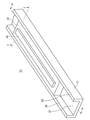
- FIG. 1 is a schematic perspective view of a gas pressure actuator 10 according to an embodiment of the present invention.
- the gas pressure actuator 10 includes a guide 12 that extends in one direction and has a concave cross section, and a rectangular parallelepiped slider 20 that is guided by the guide 12 and is movable in the axial direction along the guide 12.
- the guide 12 has a bottom wall 37, a first side wall 38, and a second side wall 39, and both ends and an intermediate portion of the bottom wall 37 are supported by a footrest (not shown).
- the slider 20 has a lid 40.
- the lid 40 closes an opening of an air servo chamber 28 (described later) formed in the slider 20.
- the air servo chamber 28 is formed so as not to penetrate the slider 20, the lid 40 is not necessary.
- the slider 20 is housed so as to have a slight gap inside the concave guide 12. As will be described in detail later, the slider 20 can move smoothly along the guide 12 by ejecting compressed gas (for example, air) from an air pad provided on the slider 20.
- compressed gas for example, air
- the gas pressure actuator 10 is used for driving a movable stage in an apparatus operating in a vacuum chamber such as an electron beam exposure apparatus.
- a vacuum chamber such as an electron beam exposure apparatus.
- the gas pressure actuator is a magnetic material, the trajectory of the electron beam may be affected. Therefore, the guide 12, the footrest, and the slider 20 are made of a nonmagnetic material such as ceramics. Is done.
- the gas pressure actuator 10 is suitable for, for example, an electron beam exposure apparatus used in a vacuum environment because there is no generation of fine dust from lubricating oil or sliding surfaces compared to, for example, a slider using a rolling bearing or a linear guide. ing.
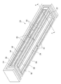
- FIG. 2 is a perspective view of the slider 20 as viewed from below
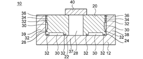
- FIG. 3 is an axial sectional view of the gas pressure actuator 10 along the line AA in FIGS.
- a plurality of air pads 30 are formed on the surface of the concave guide 12, that is, the bottom surface 22, the first side surface 24, and the second side surface 26.
- the air pad 30 ejects a high-pressure gas supplied from an air supply system (not shown), and forms a high-pressure gas layer in a minute gap between the air-fuel pad 30 and the slider 20 levitates from the guide 12.
- An air servo chamber 28 for driving the slider 20 is formed at the center of the slider 20.
- Exhaust grooves 32, 34, and 36 for differential exhaust are formed at the edges of the bottom surface 22, the first side surface 24, and the second side surface 26 of the slider 20 so as to surround the plurality of air pads 30. Accordingly, all of the exhaust grooves 32, 34, 36 include a portion extending along the axial direction of the slider 20.
- the exhaust groove 32 is open to the atmosphere.
- the exhaust groove 32 may be connected to an exhaust pump (not shown).
- the exhaust grooves 34 and 36 are respectively connected to an exhaust pump (not shown) for setting the pressure in the exhaust groove to a low vacuum pressure level and a medium vacuum pressure level, and from the air pad 30 and the air servo chamber 28 of the slider 20.
- the compressed gas supplied to the internal space is exhausted to the outside.
- the gas pressure actuator can be used even in a vacuum environment.
- the gas pressure actuator 10 is used in an atmospheric pressure environment, it is not necessary to provide such exhaust grooves 32, 34, and 36.
- the guide 12 When the guide 12 has a concave shape, depending on the load capacity of the air pad 30 disposed on the side surface of the slider 20, the guide 12 may have a wider distance between the upper end of the first side wall 38 and the upper end of the second side wall 39 (that is, It becomes easier to deform (with the upper side spreading). As a result, the desired bearing rigidity may not be ensured. Therefore, the air pad 30 on the side surface of the slider 20 is desirably arranged as close to the bottom surface 22 as possible.
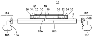
- FIG. 4 is a cross-sectional view of the gas pressure actuator taken along the line BB in FIG. 1 for explaining the operation principle of the gas pressure actuator 10.
- the gap between the guide 12 and the slider 20 and the gap between the partition wall 13 and the air servo chamber 28 are exaggerated. In practice, for example, these gaps are on the order of several microns.
- a partition wall 13 that divides the air servo chamber 28 of the slider 20 into two servo chambers 28 ⁇ / b> A and 28 ⁇ / b> B in the axial direction is fixed to the guide 12.
- the two servo chambers 28A and 28B are connected to air supply systems 17A and 17B for allowing compressed gas to enter and exit the servo chambers, respectively.
- the air supply systems 17A and 17B include servo valves 16A and 16B and compressed gas supply sources 18A and 18B, respectively.
- the slider 20 When the compressed air is supplied to the air pad 30, the slider 20 slightly floats with respect to the guide 12.
- the partition wall 13 acts as a piston, and the slider 20 moves to the left in the drawing.
- the slider 20 can be moved to an arbitrary position with respect to the guide 12 by controlling the opening degree of the servo valves 16A and 16B.
- a structure in which a substantially rectangular parallelepiped slider slides in the guide having a concave cross section is employed.
- the guide can be supported not only at both ends but also at a plurality of locations. Therefore, it is easy to ensure the flexural rigidity of the guide, and it is possible to reduce the cross-sectional area of the guide compared to the guide shaft having a square cross section. it can. Therefore, downsizing and cost reduction of the guide are realized.
- the slider can have a flat structure, the installation height of the gas pressure actuator can be suppressed. Further, since it is not necessary to form the slider in a cylindrical shape, assembly adjustment of the slider with respect to the guide can be simplified. Furthermore, since the slider and the guide can each be manufactured as an integral structure, the number of parts can be reduced.
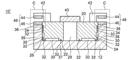
- FIG. 5 is an axial sectional view of a gas pressure actuator 10 'according to such a modification. Of the members to which the reference numerals in FIG. 5 are attached, those shown in FIG. 3 have the same configuration and will not be described.
- the magnet preload mechanism 48 applies a downward force to the slider 20 by the attractive force of the magnet.
- An L-shaped support member 42 extending from the upper surface of the slider 20 toward both side walls of the guide 12 is provided on the slider 20.
- a magnet 44 is installed on the lower surface of the support member 42, and a soft magnetic material 46 is installed on the upper part of the first side wall 38 and the second side wall 39 of the guide 12 so as to attract each other. By doing so, the bearing rigidity of the gas pressure actuator can be increased.
- the leakage magnetic field from the magnet 44 may affect the trajectory of the electron beam. Therefore, it is preferable to provide a magnetic shield around the magnet 44 and the soft magnetic material 46 (location indicated by a dotted line C in FIG. 5) to suppress the leakage magnetic field.
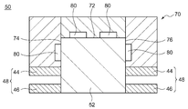
- FIG. 6 is a sectional view in the axial direction of the gas pressure actuator 50 according to such a modification.
- the guide 52 has a square cross section
- the slider 70 has a concave cross section.
- a plurality of air pads 80 are formed on the surface with respect to the guide 52, that is, the upper surface 72, the side surface 74, and the side surface 76.
- the air pad 80 ejects a high-pressure gas supplied from an air supply system (not shown) and forms a high-pressure gas layer in a minute gap between the air pad 80 and the slider 70 ascends from the guide 52.
- An air servo chamber (not shown) for driving the slider 70 is formed at the center of the slider 70.
- exhaust grooves for differential exhaust are formed at the edges of the upper surface 72, side surface 74, and side surface 76 of the slider 70 so as to surround the plurality of air pads 80.
- the exhaust grooves are respectively connected to an exhaust pump (not shown), and exhaust the compressed gas supplied to the internal space from the air pad 80 and the air servo chamber of the slider 70 to the outside.
- the magnet preload mechanism 48 is provided in order to enhance the bearing rigidity of the actuator.
- the slider and the vertical direction of the guide may be structurally connected using a linear guide or the like instead of the magnet preload mechanism. In this case, it is not necessary to provide an air pad on the slider.
- the actuator when using a linear guide, the actuator can be used in both an atmospheric pressure environment and a vacuum environment.
- an air pad, an air pad and a magnet preload mechanism, and a linear guide can be freely selected as the actuator guide mechanism.
- the actuator can be used in both an atmospheric pressure environment and a vacuum environment.
- the gas pressure actuator is made of a non-magnetic material, particularly ceramics, but the present invention can also be applied to a gas pressure actuator made of a magnetic material.
- the guide and slider of the actuator have a rectangular cross-sectional shape, but the present invention can also be applied to an actuator including a guide and a slider having an arbitrary cross-sectional shape.
- 7 to 9 are axial sectional views of a gas pressure actuator according to such a modification. 7 to 9 correspond to FIG. 3, respectively.
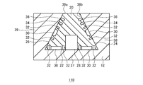
- FIG. 7 is an axial sectional view of a gas pressure actuator 110 according to a modification.
- the gas pressure actuator 110 includes a guide 12 and a slider 20.
- the slider 20 has a trapezoidal cross-sectional shape, and is inclined so that the first side surface 24 and the second side surface 26 are closer to each other toward the upper side.
- the guide 12 has a concave cross section corresponding to the slider 20. In other words, the guide 12 is inclined such that the inner surface 38a of the first side wall 38 and the inner surface 39a of the second side wall 39 are closer to each other as they move upward.
- the same operational effects as the operational effects achieved by the gas pressure actuator according to the embodiment are exhibited.
- the first side surface 24 and the second side surface 26 of the slider 20 are inclined, and the surface of the guide 12 corresponding thereto is similarly inclined. Therefore, the first side surface 24 and the second side surface 26 (and thus the slider 20) can receive a downward force from the high-pressure gas layer formed in the gap with the guide 12 by the gas ejected from the air pad 30. That is, according to this modification, the bearing rigidity of the gas pressure actuator is increased.
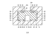
- FIG. 8 is an axial sectional view of a gas pressure actuator 210 according to a modification.
- the gas pressure actuator 210 includes the guide 12 and the slider 20.
- the slider 20 has a rectangular cross-sectional shape, and the guide 12 has a concave cross-sectional shape.
- first side wall 38 and the second side wall 39 of the guide 12 have an L-shaped cross-sectional shape.
- the first side wall 38 and the second side wall 39 respectively have a first extension part 38b and a second extension part 39b extending toward each other.
- the guide 12 has an upper wall in addition to the bottom wall 37, the first side wall 38, and the second side wall 39, and a part (central portion) of the upper wall is opened.
- An air pad 30 is formed on the upper surface of the slider 20 at a portion corresponding to the first extension portion 38b and the second extension portion 39b.
- the same operational effects as the operational effects achieved by the gas pressure actuator according to the embodiment are exhibited.
- the air pad 30 is formed on the upper surface of the slider 20 with respect to the first extension portion 38b and the second extension portion 39b. Therefore, the slider 20 can receive a downward force from the high-pressure gas layer formed in the gap with the guide 12 by the gas ejected from the air pad 30. That is, according to this modification, the bearing rigidity of the gas pressure actuator is increased.
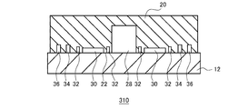
- FIG. 9 is an axial sectional view of a gas pressure actuator 310 according to a modification.
- the gas pressure actuator 310 includes the guide 12 and the slider 20.
- the guide 12 and the slider 20 have a rectangular cross-sectional shape. Note that the guide 12 and the slider 20 are not limited to a rectangular cross-sectional shape, and may have a polygonal cross-sectional shape. In this modification, the guide 12 is open on three sides.
- a plurality of air pads 30 are formed on the surface with respect to the guide 12, that is, the bottom surface 22. Further, exhaust grooves 32, 34, 36 for differential exhaust are formed on the bottom surface 22 of the slider 20 so as to surround the plurality of air pads 30.
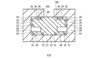
- FIG. 10 is an axial sectional view of a gas pressure actuator 420 according to such a modification.
- FIG. 10 corresponds to FIG.
- air servo chambers 28 are formed on the first side surface 24 and the second side surface 26, respectively. That is, the two air servo chambers 28 are formed so as to face the inner surface 38a and the inner surface 39a that face each other with the slider 20 in between.
- this modification even if pressure fluctuations occur in the two air servo chambers 28, the forces due to the pressure fluctuations are canceled in the two air servo chambers 28. For this reason, even if a pressure fluctuation occurs in the air servo chamber 28, it is possible to prevent the pressure fluctuation from affecting the slider 20 and the guide 12.
- gas pressure actuators 10 gas pressure actuators, 12 guides, 20 sliders, 30 air pads, 34 exhaust grooves, 44 magnets, 48 magnet preload mechanisms, 50 gas pressure actuators, 52 guides, 70 sliders, 80 air pads.
- the actuator that can move while the slider is guided by the guide can have a simple structure.
Landscapes
- Engineering & Computer Science (AREA)
- General Engineering & Computer Science (AREA)
- Mechanical Engineering (AREA)
- Physics & Mathematics (AREA)
- Fluid Mechanics (AREA)
- Chemical & Material Sciences (AREA)
- Analytical Chemistry (AREA)
- Magnetic Bearings And Hydrostatic Bearings (AREA)
- Actuator (AREA)
- Bearings For Parts Moving Linearly (AREA)
- Support Of The Bearing (AREA)
Abstract
Description
Claims (13)
- 一方向に延びるガイドと、該ガイドに対して軸方向に移動可能なスライダと、を備えるアクチュエータであって、
前記ガイドは、少なくとも一面が開放され、
前記スライダは、圧縮気体を噴出するエアパッドと該スライダを駆動するためのエアサーボ室とを有し、前記ガイドに対して浮上して案内されるように構成されることを特徴とするアクチュエータ。 - 前記ガイドは凹形断面を有し、前記スライダは該凹形断面を構成する三面で拘束されつつ、前記ガイドに対して浮上して案内されるように構成されることを特徴とする請求項1に記載のアクチュエータ。
- 前記ガイドは多角形断面を有し、前記スライダは該多角形断面を構成する複数の面のうちの一面で拘束されつつ、前記ガイドに対して浮上して案内されるように構成されることを特徴とする請求項1に記載のアクチュエータ。
- 前記スライダと前記ガイドとの間に、磁力による下向きの力を前記スライダに付与するマグネットプリロード機構が設けられることを特徴とする請求項1ないし3のいずれかに記載のアクチュエータ。
- 一方向に延びるガイドと、該ガイドに対して軸方向に移動可能なスライダと、を備えるアクチュエータであって、
前記ガイドは、少なくとも一面が開放され、
前記スライダは、圧縮気体を噴出するエアパッドと該エアパッドから噴出される圧縮空気を排出する排気溝とを有し、前記ガイドに対して浮上して案内されるように構成され、
前記排気溝は前記軸方向に延びる部分を含むことを特徴とするアクチュエータ。 - 前記ガイドは凹形断面を有し、前記スライダは該凹形断面を構成する三面で拘束されつつ、前記ガイドに対して浮上して案内されるように構成されることを特徴とする請求項5に記載のアクチュエータ。
- 前記ガイドは多角形断面を有し、前記スライダは該多角形断面を構成する複数の面のうちの一面で拘束されつつ、前記ガイドに対して浮上して案内されるように構成されることを特徴とする請求項5に記載のアクチュエータ。
- 前記スライダと前記ガイドとの間に、磁力による下向きの力を前記スライダに付与するマグネットプリロード機構が設けられることを特徴とする請求項5ないし7のいずれかに記載のアクチュエータ。
- 一方向に延びるガイドと、該ガイドに対して軸方向に移動可能なスライダと、を備えるアクチュエータであって、
前記ガイドまたは前記スライダの一方が凹形断面を有し、他方が該凹形断面を構成する三面で拘束されつつ、前記スライダが前記ガイドにより案内されることを特徴とするアクチュエータ。 - 前記スライダは、圧縮気体を噴出するエアパッドを有しており、前記ガイドに対して浮上して案内されるように構成されることを特徴とする請求項9に記載のアクチュエータ。
- 前記スライダは、前記エアパッドから噴出される圧縮空気を排出する排気溝をさらに有し、
前記排気溝は、前記軸方向に延びる部分を含むことを特徴とする請求項10に記載のアクチュエータ。 - 前記スライダは、軸方向に延びるエアサーボ室を有し、
前記ガイドは、前記エアサーボ室に進入して前記エアサーボ室を2つに区画する隔壁を有し、
前記スライダは、前記エアサーボ室の2つの区画のうちの一方の区画に圧縮気体を供給されるとともに他方の区画から圧縮気体を排出されることにより、ガイドに対して軸方向に移動することを特徴とする請求項9ないし11のいずれかに記載のアクチュエータ。 - 前記スライダと前記ガイドとの間に、磁力による下向きの力を前記スライダに付与するマグネットプリロード機構が設けられることを特徴とする請求項9ないし12のいずれかに記載のアクチュエータ。
Priority Applications (6)
| Application Number | Priority Date | Filing Date | Title |
|---|---|---|---|
| EP16772113.3A EP3279486B1 (en) | 2015-03-31 | 2016-03-08 | Actuator |
| KR1020177025387A KR102415241B1 (ko) | 2015-03-31 | 2016-03-08 | 액추에이터 |
| JP2017509452A JP6893170B2 (ja) | 2015-03-31 | 2016-03-08 | アクチュエータ |
| CN202210177825.5A CN114607701A (zh) | 2015-03-31 | 2016-03-08 | 致动器 |
| CN201680015987.1A CN107429738A (zh) | 2015-03-31 | 2016-03-08 | 致动器 |
| US15/713,159 US10371279B2 (en) | 2015-03-31 | 2017-09-22 | Actuator |
Applications Claiming Priority (2)
| Application Number | Priority Date | Filing Date | Title |
|---|---|---|---|
| JP2015-072054 | 2015-03-31 | ||
| JP2015072054 | 2015-03-31 |
Related Child Applications (1)
| Application Number | Title | Priority Date | Filing Date |
|---|---|---|---|
| US15/713,159 Continuation US10371279B2 (en) | 2015-03-31 | 2017-09-22 | Actuator |
Publications (1)
| Publication Number | Publication Date |
|---|---|
| WO2016158229A1 true WO2016158229A1 (ja) | 2016-10-06 |
Family
ID=57004162
Family Applications (1)
| Application Number | Title | Priority Date | Filing Date |
|---|---|---|---|
| PCT/JP2016/057070 Ceased WO2016158229A1 (ja) | 2015-03-31 | 2016-03-08 | アクチュエータ |
Country Status (7)
| Country | Link |
|---|---|
| US (1) | US10371279B2 (ja) |
| EP (1) | EP3279486B1 (ja) |
| JP (2) | JP6893170B2 (ja) |
| KR (1) | KR102415241B1 (ja) |
| CN (2) | CN114607701A (ja) |
| TW (1) | TWI589802B (ja) |
| WO (1) | WO2016158229A1 (ja) |
Cited By (1)
| Publication number | Priority date | Publication date | Assignee | Title |
|---|---|---|---|---|
| WO2018070151A1 (ja) * | 2016-10-13 | 2018-04-19 | 住友重機械工業株式会社 | ステージ装置 |
Families Citing this family (4)
| Publication number | Priority date | Publication date | Assignee | Title |
|---|---|---|---|---|
| JP6696821B2 (ja) * | 2016-04-26 | 2020-05-20 | Dmg森精機株式会社 | 工作機械 |
| JP7539822B2 (ja) * | 2020-12-07 | 2024-08-26 | 住友重機械工業株式会社 | 気体圧アクチュエータの制御方法および制御演算装置 |
| JP7702368B2 (ja) | 2022-02-25 | 2025-07-03 | 住友重機械工業株式会社 | アクチュエータ、ステージ装置、露光装置、検査装置 |
| JPWO2024190524A1 (ja) * | 2023-03-13 | 2024-09-19 |
Citations (3)
| Publication number | Priority date | Publication date | Assignee | Title |
|---|---|---|---|---|
| JPS6441727U (ja) * | 1987-09-09 | 1989-03-13 | ||
| JPH11190306A (ja) * | 1997-12-25 | 1999-07-13 | Ntn Corp | エアスライド装置 |
| JP2002257138A (ja) * | 2001-02-28 | 2002-09-11 | Canon Inc | 静圧流体軸受装置、およびこれを用いたステージ装置、露光装置ならびにデバイス製造方法 |
Family Cites Families (20)
| Publication number | Priority date | Publication date | Assignee | Title |
|---|---|---|---|---|
| JPS6237514A (ja) * | 1985-08-10 | 1987-02-18 | Omron Tateisi Electronics Co | 静圧軸受装置 |
| JPH0429616A (ja) * | 1990-05-24 | 1992-01-31 | Nagase Iron Works Co Ltd | 流体通過装置 |
| JP4144179B2 (ja) * | 1998-06-17 | 2008-09-03 | 株式会社ニコン | 静圧気体軸受およびそれを用いたステージ装置およびそれを用いた光学装置 |
| IL131647A0 (en) * | 1999-08-30 | 2001-01-28 | Leonid Kashchenevsky | Method and device to control the accuracy of movement of a unit moving linearly on hydro- or aerostatic slides |
| JP2001173654A (ja) | 1999-12-15 | 2001-06-26 | Nikon Corp | 静圧軸受装置及びそれを用いた光学装置 |
| US7052182B2 (en) * | 2000-02-01 | 2006-05-30 | Toto Ltd. | Hydrostatic gas bearing, hydrostatic gas bearing device for use in vacuum environment, and gas recovering method for the hydrostatic gas bearing device |
| JP2002170765A (ja) * | 2000-12-04 | 2002-06-14 | Nikon Corp | ステージ装置及び露光装置 |
| JP4443778B2 (ja) * | 2001-02-07 | 2010-03-31 | 住友重機械工業株式会社 | 流体圧アクチュエータ |
| JP2002252166A (ja) * | 2001-02-27 | 2002-09-06 | Canon Inc | ステージ装置、露光装置およびデバイス製造方法ならびに移動案内方法 |
| JP4031252B2 (ja) * | 2002-01-31 | 2008-01-09 | キヤノン株式会社 | 排気装置及びその制御方法並びに真空内静圧軸受 |
| JP2004128308A (ja) * | 2002-10-04 | 2004-04-22 | Nikon Corp | ステージ装置及び露光装置 |
| JP4269711B2 (ja) * | 2003-02-20 | 2009-05-27 | Toto株式会社 | 静圧気体軸受 |
| JP2006029395A (ja) * | 2004-07-13 | 2006-02-02 | Konica Minolta Opto Inc | 静圧スライド |
| DE102005038346A1 (de) * | 2005-08-13 | 2007-02-15 | Schaeffler Kg | Hydrostatische Profilschienenführung |
| DE102006018312A1 (de) * | 2006-04-20 | 2007-10-25 | Schaeffler Kg | Hydrostatische Profilschienenführung |
| JP2010151176A (ja) * | 2008-12-24 | 2010-07-08 | Nsk Ltd | アクチュエータ |
| JP2011247405A (ja) * | 2009-07-30 | 2011-12-08 | Kyocera Corp | 案内装置 |
| EP2541588B1 (en) * | 2010-02-23 | 2017-07-12 | Advantest Corporation | Stage device |
| JP5953751B2 (ja) * | 2012-01-04 | 2016-07-20 | 株式会社Ihi | 案内装置及び流路形成方法 |
| NL2011519C2 (en) * | 2013-09-27 | 2015-03-30 | Ccm Beheer Bv | Hydrogenerator. |
-
2016
- 2016-03-08 EP EP16772113.3A patent/EP3279486B1/en active Active
- 2016-03-08 CN CN202210177825.5A patent/CN114607701A/zh active Pending
- 2016-03-08 KR KR1020177025387A patent/KR102415241B1/ko active Active
- 2016-03-08 CN CN201680015987.1A patent/CN107429738A/zh active Pending
- 2016-03-08 WO PCT/JP2016/057070 patent/WO2016158229A1/ja not_active Ceased
- 2016-03-08 JP JP2017509452A patent/JP6893170B2/ja active Active
- 2016-03-25 TW TW105109510A patent/TWI589802B/zh active
-
2017
- 2017-09-22 US US15/713,159 patent/US10371279B2/en active Active
-
2021
- 2021-03-05 JP JP2021035646A patent/JP7122423B2/ja active Active
Patent Citations (3)
| Publication number | Priority date | Publication date | Assignee | Title |
|---|---|---|---|---|
| JPS6441727U (ja) * | 1987-09-09 | 1989-03-13 | ||
| JPH11190306A (ja) * | 1997-12-25 | 1999-07-13 | Ntn Corp | エアスライド装置 |
| JP2002257138A (ja) * | 2001-02-28 | 2002-09-11 | Canon Inc | 静圧流体軸受装置、およびこれを用いたステージ装置、露光装置ならびにデバイス製造方法 |
Non-Patent Citations (1)
| Title |
|---|
| See also references of EP3279486A4 * |
Cited By (1)
| Publication number | Priority date | Publication date | Assignee | Title |
|---|---|---|---|---|
| WO2018070151A1 (ja) * | 2016-10-13 | 2018-04-19 | 住友重機械工業株式会社 | ステージ装置 |
Also Published As
| Publication number | Publication date |
|---|---|
| JP2021099165A (ja) | 2021-07-01 |
| TWI589802B (zh) | 2017-07-01 |
| TW201636523A (zh) | 2016-10-16 |
| EP3279486A1 (en) | 2018-02-07 |
| EP3279486B1 (en) | 2022-02-23 |
| JP6893170B2 (ja) | 2021-06-23 |
| JP7122423B2 (ja) | 2022-08-19 |
| KR102415241B1 (ko) | 2022-06-29 |
| CN107429738A (zh) | 2017-12-01 |
| US20180010709A1 (en) | 2018-01-11 |
| US10371279B2 (en) | 2019-08-06 |
| KR20170134368A (ko) | 2017-12-06 |
| CN114607701A (zh) | 2022-06-10 |
| EP3279486A4 (en) | 2018-12-05 |
| JPWO2016158229A1 (ja) | 2018-01-25 |
Similar Documents
| Publication | Publication Date | Title |
|---|---|---|
| JP7122423B2 (ja) | アクチュエータ、ステージ装置および露光装置 | |
| US11335491B2 (en) | Fluid servo valve and fluid servo apparatus | |
| US6674085B2 (en) | Gas-actuated stages including reaction-force-canceling mechanisms for use in charged-particle-beam microlithography systems | |
| CN102545531B (zh) | 线性致动器 | |
| US11002313B2 (en) | Active aerostatic bearing | |
| JP2004134682A (ja) | 気体シリンダ、ステージ装置及び露光装置 | |
| KR102423262B1 (ko) | 정압기체베어링 | |
| JP6967760B2 (ja) | Xyステージ移動機構 | |
| WO2018070151A1 (ja) | ステージ装置 | |
| JP7328975B2 (ja) | ステージ装置 | |
| JP2005003163A (ja) | 精密気体圧制御弁 | |
| JPH05215131A (ja) | 直線運動装置用の直線状スライド | |
| KR102168401B1 (ko) | 중력보상 구동부 | |
| JP4443778B2 (ja) | 流体圧アクチュエータ | |
| JP2010151322A (ja) | Xyステージ | |
| JP4273743B2 (ja) | 位置決め装置 | |
| US20020021427A1 (en) | Cantilever reticle stage for electron beam projection lithography system | |
| JP2023104051A (ja) | ステージ装置、荷電粒子線装置及び真空装置 | |
| JP2002093685A (ja) | ステージ装置及び露光装置 |
Legal Events
| Date | Code | Title | Description |
|---|---|---|---|
| 121 | Ep: the epo has been informed by wipo that ep was designated in this application |
Ref document number: 16772113 Country of ref document: EP Kind code of ref document: A1 |
|
| ENP | Entry into the national phase |
Ref document number: 2017509452 Country of ref document: JP Kind code of ref document: A |
|
| ENP | Entry into the national phase |
Ref document number: 20177025387 Country of ref document: KR Kind code of ref document: A |
|
| REEP | Request for entry into the european phase |
Ref document number: 2016772113 Country of ref document: EP |
|
| NENP | Non-entry into the national phase |
Ref country code: DE |