WO2016158645A1 - ベーン型圧縮機 - Google Patents
ベーン型圧縮機 Download PDFInfo
- Publication number
- WO2016158645A1 WO2016158645A1 PCT/JP2016/059318 JP2016059318W WO2016158645A1 WO 2016158645 A1 WO2016158645 A1 WO 2016158645A1 JP 2016059318 W JP2016059318 W JP 2016059318W WO 2016158645 A1 WO2016158645 A1 WO 2016158645A1
- Authority
- WO
- WIPO (PCT)
- Prior art keywords
- opening
- valve body
- valve
- suction port
- guide portion
- Prior art date
- Legal status (The legal status is an assumption and is not a legal conclusion. Google has not performed a legal analysis and makes no representation as to the accuracy of the status listed.)
- Ceased
Links
Images


Classifications
-
- F—MECHANICAL ENGINEERING; LIGHTING; HEATING; WEAPONS; BLASTING
- F04—POSITIVE - DISPLACEMENT MACHINES FOR LIQUIDS; PUMPS FOR LIQUIDS OR ELASTIC FLUIDS
- F04B—POSITIVE-DISPLACEMENT MACHINES FOR LIQUIDS; PUMPS
- F04B39/00—Component parts, details, or accessories, of pumps or pumping systems specially adapted for elastic fluids, not otherwise provided for in, or of interest apart from, groups F04B25/00 - F04B37/00
- F04B39/10—Adaptations or arrangements of distribution members
-
- F—MECHANICAL ENGINEERING; LIGHTING; HEATING; WEAPONS; BLASTING
- F04—POSITIVE - DISPLACEMENT MACHINES FOR LIQUIDS; PUMPS FOR LIQUIDS OR ELASTIC FLUIDS
- F04C—ROTARY-PISTON, OR OSCILLATING-PISTON, POSITIVE-DISPLACEMENT MACHINES FOR LIQUIDS; ROTARY-PISTON, OR OSCILLATING-PISTON, POSITIVE-DISPLACEMENT PUMPS
- F04C18/00—Rotary-piston pumps specially adapted for elastic fluids
- F04C18/30—Rotary-piston pumps specially adapted for elastic fluids having the characteristics covered by two or more of groups F04C18/02, F04C18/08, F04C18/22, F04C18/24, F04C18/48, or having the characteristics covered by one of these groups together with some other type of movement between co-operating members
- F04C18/34—Rotary-piston pumps specially adapted for elastic fluids having the characteristics covered by two or more of groups F04C18/02, F04C18/08, F04C18/22, F04C18/24, F04C18/48, or having the characteristics covered by one of these groups together with some other type of movement between co-operating members having the movement defined in group F04C18/08 or F04C18/22 and relative reciprocation between the co-operating members
- F04C18/344—Rotary-piston pumps specially adapted for elastic fluids having the characteristics covered by two or more of groups F04C18/02, F04C18/08, F04C18/22, F04C18/24, F04C18/48, or having the characteristics covered by one of these groups together with some other type of movement between co-operating members having the movement defined in group F04C18/08 or F04C18/22 and relative reciprocation between the co-operating members with vanes reciprocating with respect to the inner member
-
- F—MECHANICAL ENGINEERING; LIGHTING; HEATING; WEAPONS; BLASTING
- F04—POSITIVE - DISPLACEMENT MACHINES FOR LIQUIDS; PUMPS FOR LIQUIDS OR ELASTIC FLUIDS
- F04C—ROTARY-PISTON, OR OSCILLATING-PISTON, POSITIVE-DISPLACEMENT MACHINES FOR LIQUIDS; ROTARY-PISTON, OR OSCILLATING-PISTON, POSITIVE-DISPLACEMENT PUMPS
- F04C29/00—Component parts, details or accessories of pumps or pumping installations, not provided for in groups F04C18/00 - F04C28/00
- F04C29/12—Arrangements for admission or discharge of the working fluid, e.g. constructional features of the inlet or outlet
- F04C29/124—Arrangements for admission or discharge of the working fluid, e.g. constructional features of the inlet or outlet with inlet and outlet valves specially adapted for rotary or oscillating piston pumps
- F04C29/126—Arrangements for admission or discharge of the working fluid, e.g. constructional features of the inlet or outlet with inlet and outlet valves specially adapted for rotary or oscillating piston pumps of the non-return type
-
- F—MECHANICAL ENGINEERING; LIGHTING; HEATING; WEAPONS; BLASTING
- F16—ENGINEERING ELEMENTS AND UNITS; GENERAL MEASURES FOR PRODUCING AND MAINTAINING EFFECTIVE FUNCTIONING OF MACHINES OR INSTALLATIONS; THERMAL INSULATION IN GENERAL
- F16K—VALVES; TAPS; COCKS; ACTUATING-FLOATS; DEVICES FOR VENTING OR AERATING
- F16K15/00—Check valves
- F16K15/02—Check valves with guided rigid valve members
- F16K15/025—Check valves with guided rigid valve members the valve being loaded by a spring
Definitions
- the present invention relates to a vane type compressor, and more particularly, to a vane type compressor with improved check valve operability.
- a structure in which a check valve is provided in the vicinity of a suction port of a compressor in order to prevent a backflow of refrigerant gas from a low-pressure chamber of the compressor to an external refrigeration cycle.
- the check valve is opened during operation of the compressor, and the low-pressure refrigerant sucked from the external refrigeration cycle is sucked into the low-pressure chamber from the suction port.
- the check valve closes to prevent the refrigerant in the compression chamber in the compression process from reversing the compression mechanism and backflowing from the suction port to the cooling heat exchanger side external refrigeration cycle.
- a guide cylinder valve case
- an urging means spring
- a valve body and a valve seat are inserted into a suction port formed in the front head, and the posture of the valve body is controlled by the valve case.
- a configuration is disclosed (for example, see Patent Document 1).
- the valve case may be deformed when the valve case is fixed to the front head. Therefore, a check valve in which the valve case is integrated with the front head has been proposed (see, for example, Patent Documents 2 to 4).
- An object of the present invention relates to a check valve in which a valve case is integrated with a front head, and provides a vane compressor with improved check valve operability in order to reduce passage resistance of the check valve. That is.
- a vane type compressor includes a housing having a suction port for sucking refrigerant gas from an external refrigeration cycle, a low pressure chamber communicating with the suction port, and the refrigerant gas from the low pressure chamber to the external refrigeration cycle.
- the check valve is provided in the suction port, and has a valve seat having a suction port formed in the center thereof, and a contact with the valve seat.
- a cylindrical valve body having a contact portion, a biasing member that biases the valve body in a direction to contact the valve seat, and a guide that is formed integrally with the housing and slidably accommodates the valve body
- the guide portion has an opening portion in which a part of the peripheral wall is opened to the low pressure chamber, and the peripheral surface portion of the valve body slides along the inner wall of the guide portion, The opening area of the opening changes, and the valve seat That with increasing distance of the valve body, the rate of change of the opening area of the opening corresponding to the change in the distance is characterized by changes stepwise from low to high.
- the maximum value of the opening area when the ratio of the change amount of the opening area to the change amount of the separation distance is small is based on the area of the suction port formed by the valve seat. Is preferably small.
- the pressure drop passing through the opening is relatively larger than the pressure drop passing through the suction port (also referred to as pressure loss), and the pressure acting on the upstream side of the valve body is relatively reduced.
- the check valve can be fully opened by pressing down the valve body to the bottom surface of the guide portion as soon as the compressor starts operating.
- the opening is connected in order from the suction port side to the first opening and the first opening, and the circumferential direction of the valve body is more than the first opening. It is preferable to have a 2nd opening part with a wide opening space
- the guide portion includes a support portion that supports a peripheral surface portion of the valve body so as to suppress an inclination of the valve body, and the support portion includes the valve body of the valve body.
- the contact portion is in the second opening, it is preferable to support at least half of the height of the peripheral surface portion of the valve body.
- the opening is preferably opened in a direction parallel to the rotation axis direction of the rotor.
- the valve body is formed so that a boundary between the peripheral surface portion and the contact portion has an R shape. This makes it difficult for the valve body to be caught in the opening, and the operability of the check valve can be further improved.
- the guide portion has an annular refrigerant flow groove whose diameter is increased at the inner peripheral surface of the peripheral wall of the guide portion at the end opposite to the suction port side. Is preferred.
- the refrigerant gas that has flowed into the bottom of the guide portion passes through the refrigerant flow groove, so that the retention of gas in the cylinder of the valve body can be reduced and the valve body can be pushed down to the bottom surface of the guide portion.
- the support portion is provided with a third opening portion connected to the second opening portion.
- the flow resistance of the refrigerant gas can be reduced.
- the retention of gas in the cylinder of the valve body can be reduced, and the valve body can be pushed down to the bottom surface of the guide portion.
- the state where the valve body is pushed down can be maintained.
- the flow rate of the refrigerant gas in the central axis direction of the valve body can be increased.
- an end of the third opening opposite to the second opening is inclined with respect to a direction orthogonal to the central axis direction of the valve body. Is preferred. As a result, the exhaustability of the lubricating oil or the refrigerant gas from the guide portion can be improved. In addition, the lower end of the valve body is not easily caught by the end of the third opening, and the valve body can easily move downward.
- the present invention relates to a check valve in which a valve case is integrated with a front head, and provides a vane compressor with improved check valve operability in order to reduce passage resistance of the check valve. it can.
- FIGS. 4A and 4B are examples of a cross-sectional shape of the guide portion, where FIG. 4A is a cross-sectional view taken along the line AA in FIG. 4, FIG. 4D is a sectional view taken along the line DD of FIG. 4, and FIG. 4E is a sectional view taken along the line EE of FIG.
- FIG. 6 is a front view showing a check valve of Comparative Example 1.
- FIG. It is a graph which shows the relationship between a separation distance and opening area.
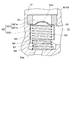
- a vane compressor 1 includes a housing 10 having a suction port 12 that sucks refrigerant gas from an external refrigeration cycle (not shown) and a low-pressure chamber 13 that communicates with the suction port 12. And a check valve 50 for preventing the backflow of the refrigerant gas from the low pressure chamber 13 to the external refrigeration cycle, the check valve 50 includes a suction port as shown in FIGS. 12, a valve seat 51 having a suction port 51a formed in the center, a cylindrical valve body 52 having an abutting portion 521b that abuts the valve seat 51, and the valve body 52 abutting against the valve seat.
- the vane type compressor 1 is a part of a refrigeration cycle (not shown), compresses the refrigerant gas vaporized in a cooling heat exchanger (not shown), and converts the high-temperature and high-pressure gas into a condenser (Not shown).
- the vane compressor 1 will be briefly described with reference to FIG.
- the basic structure of the vane compressor 1 other than the check valve 50 is not particularly limited.
- the housing 10 includes a rear head 7 fixed to the rear side end surface of the cam ring 2, and a front head 8 that surrounds the front side end surface and outer peripheral surface of the cam ring 2 and is fitted to the rear head 7.
- the suction port 12 is a substantially cylindrical opening formed integrally with the front head 8 and sucks the refrigerant gas vaporized by a cooling heat exchanger (not shown).
- the low pressure chamber 13 is a space formed in the front head 8 and communicates with the suction port 12.
- the rear head 7 is provided with a discharge port 14 that discharges the refrigerant gas and a high-pressure chamber 15 that communicates with the discharge port 14.
- a cam ring 2 and a rotor 4 that is rotatably accommodated in the cam ring 2 and fixed to the rotary shaft 3 are disposed.
- the rotor 4 is provided with a plurality of vane grooves 5, and a vane 6 is inserted into each vane groove 5.
- An elliptical space 9 is formed on the inner peripheral surface of the cam ring 2, and the perfect rotor 4 is arranged in the space 9, so that the space between the inner peripheral surface of the cam ring 2 and the outer peripheral surface of the rotor 4 is set.
- a compression space 16 is formed.
- the compression space 16 is partitioned by the vanes 6 to form a plurality of compression chambers 17.
- the volume of each compression chamber 17 changes with the rotation of the rotor 4.
- the check valve 50 is disposed at the boundary between the suction port 12 and the low pressure chamber 13 as shown in FIG. Next, the check valve 50 will be described with reference to FIGS.
- the check valve 50 includes a valve seat 51, a valve body 52, an urging member 53, and a guide portion 54.
- the valve seat 51 is an annular member having a suction port 51a formed in the center, and is press-fitted into the suction port 12 and fixed.
- the valve body 52 is a cylindrical member having a closed portion 521 and a peripheral surface portion 522 depending from the periphery of the closed portion 521.
- the closing part 521 has a protruding part 521a in which the center of the closing part 521 is protruded in a mountain shape, and a flat contact part 521b provided around the protruding part 521a.
- the boundary between the peripheral surface portion 522 of the valve body and the contact portion 521b is preferably formed to have an R shape. This makes it difficult for the valve body 52 to be caught by the opening 55, and the operability of the check valve 50 can be further improved.
- the range of R is not particularly limited, but is preferably R1 mm to R2 mm, for example.
- the biasing member 53 is a coil spring, for example, and is inserted into the cylinder of the valve body 52.
- the guide portion 54 is integrally formed inside the front head 8.
- the valve body 52 is slidably accommodated in the internal space of the guide portion 54.
- a hole 54 a communicating with the shaft seal chamber 19 may be provided on the bottom surface of the guide portion 54.
- the guide portion 54 is an end portion opposite to the suction port 12 side, and the inner peripheral surface of the peripheral wall of the guide portion 54 is expanded in diameter. It is preferable to have an annular coolant circulation groove 56.
- 5A and 5B are examples of the cross-sectional shape of the guide portion.
- FIG. 5A is a cross-sectional view taken along the line AA in FIG. 4
- FIG. 5B is a cross-sectional view taken along the line BB in FIG.
- FIG. 4C is a sectional view taken along line -C
- FIG. 4D is a sectional view taken along line DD in FIG. 4
- FIG. 4E is a sectional view taken along line EE in FIG.
- FIG. 5A is a cross-sectional view taken along the line AA in FIG. 4
- FIG. 5B is a cross-sectional view taken along the line BB in FIG.
- FIG. 4C is a sectional view taken along line -C
- FIG. 4D is a sectional
- the virtual outer peripheral surface shape 52 ⁇ / b> F in the case where the valve element exists in the cross section is indicated by a two-dot chain line.
- the guide portion 54 preferably further includes a longitudinal groove 57 that intersects the refrigerant flow groove 56 and connects the refrigerant flow groove 56 and the suction port 12.
- the number of the longitudinal grooves 57 is not particularly limited, and may be one or two or more.
- FIGS. 5A to 5D show an example in which there are two longitudinal grooves 57 as an example.
- the opening 55 is a hole formed in the peripheral wall facing the low pressure chamber 13 in the peripheral wall of the guide portion 54 as shown in FIG.
- the suction port 12 is communicated with the low pressure chamber 13 through the opening 55.
- the opening 55 is preferably opened in a direction parallel to the direction of the rotation axis 3 of the rotor 4 as shown in FIG. Accordingly, the refrigerant gas inflow path from the suction port 12 to the compression chamber 17 is shortened, so that the flow resistance of the refrigerant gas can be reduced. As a result, the refrigerant gas can flow smoothly to the compression mechanism side.
- the opening 55 is not partitioned by the peripheral wall. Since there is only one opening 55 in the circumferential direction of the valve body 52, the refrigerant gas can be concentrated and flowed in one opening 55 without being divided, and can be smoothly supplied to the compression mechanism side. For this reason, compared with the case where there are a plurality of openings 55 in the circumferential direction of the valve body 52, an allowable pressure drop can be assigned and set only to the pressure drop at the openings. As a result, the check valve 50 can be fully opened by quickly pressing the valve body 52 toward the bottom surface of the guide portion 54.
- the circumferential direction of the valve body 52 refers to the circumferential direction of the circumferential surface portion 522 of the valve body.
- the opening 55 opens in a direction parallel to the direction of the rotation axis 3 of the rotor 4 and has only one opening in the circumferential direction of the valve body 52.
- the opening area A [mm 2 ] of the opening 55 changes as the peripheral surface portion 522 of the valve body slides along the inner wall of the guide portion 54.
- the suction port 51a of the valve seat 51 is closed by the contact portion 521b of the valve body, and the entire opening 55 is formed. Is closed by the valve body 52, and the opening area A is zero.
- the suction port 51a is opened from the closed state, and a part of the opening 55 is opened, and the separation distance L [mm] of the valve body 52 from the valve seat 51 is opened. As the distance increases, the opening area A increases.
- the opening area A is the area of the open portion of the opening 55 in the area of the virtual surface obtained by virtually extending the inner wall surface of the guide portion 54 into the opening 55.
- the virtual surface has a cylindrical peripheral surface shape.
- FIG. 6 is a conceptual diagram for explaining a gradual change in the ratio of the change amount of the opening area of the opening to the change amount of the separation distance.
- the ratio of the change amount of the opening area A of the opening 55 to the change amount of the separation distance L (hereinafter sometimes referred to as dA / dL) is small. It changes gradually.
- dA / dL changes stepwise means that a graph 900 created with the separation distance L on the X axis and dA / dL on the Y axis has a step 901 as shown in FIG.
- dA / dL before the step is smaller than dA / dL after the step.
- the present invention is not limited to the shape of the graph 900 and the level of the step 901.
- the maximum value of the opening area A when the ratio of the change amount of A to the change amount of L is small is smaller than the area of the suction port 51a formed by the valve seat 51. It is preferable. As a result, the pressure drop passing through the opening 55 is relatively larger than the pressure drop of the refrigerant gas passing through the suction port 51a, and the pressure acting on the upstream side of the valve element can be increased. As a result, the check valve 50 can be fully opened by pressing down the valve body 52 to the bottom surface of the guide portion 54 as soon as the compressor starts operating.
- the opening 55 is connected to the first opening 55a and the first opening 55a in order from the suction port 12 (shown in FIG. 2) side. And it is preferable to have the 2nd opening part 55b with which the opening space
- the valve body 52 When the refrigerant is sucked from the suction port 12 by starting the compressor, the valve body 52 is lifted away from the valve seat 51. Immediately after the start of the lift, the contact portion 521b of the valve body is in the first opening 55a, and the ratio of the change amount of A to the change amount of L is relatively small. For this reason, even if the separation distance L of the valve body 52 increases as the refrigerant flow rate increases, the opening area A increases slowly, and the pressure on the upstream side of the valve body 52 is increased. As a result, the increased pressure on the upstream side of the valve body 52 can push down the valve body 52 toward the bottom surface of the guide portion 54 and help the check valve 50 to be fully opened.
- the opening area of the opening 55 when the check valve 50 is fully open is preferably larger than the area of the suction port 51 a formed by the valve seat 51.
- the length of the opening 55 (the length of the valve body 52 in the direction of the central axis O) is set. If the length is not increased, the opening area when the check valve 50 is fully opened becomes relatively small, and the passage resistance of the check valve 50 cannot be sufficiently reduced.
- the opening 55 has the second opening 55b having a larger opening interval in the circumferential direction of the valve body 52 than the first opening 55a, so that the length of the opening 55 is not increased. Even when the check valve 50 is fully open, a sufficient opening area can be secured. As a result, the valve body 52 can easily reach the bottom surface of the guide portion 54, and a sufficient opening area can be secured to reduce the pressure drop at the opening portion.
- the guide portion 54 has the first opening 55 a, the inclination of the valve body 52 immediately after the valve body 52 is separated from the valve seat 51 can be suppressed. Since the guide part 54 has the support part 58, the inclination of the valve body 52 when the contact part 521b of a valve body exists in the 2nd opening part 55b can be suppressed more. As a result, the operability of the check valve 50 can be further improved.
- the guide portion 54 includes a support portion 58 that supports the peripheral surface portion 522 of the valve body so as to suppress the inclination of the valve body 52, and the support portion 58 includes the valve body.
- the abutting portion 521b is located in the second opening 55b, it is preferable to support half or more of the height of the peripheral surface portion 522 of the valve body. Thereby, the inclination of the valve body can be further suppressed. As a result, the operability of the check valve can be further improved.
- the first opening 55a preferably has a shape in which the circumferential length of the valve body 52 is constant in the direction of the central axis O of the valve body 52, as shown in FIG.
- the valve body 52 moves up and down in the guide portion 54 while the inclination is suppressed by the inner wall of the guide portion 54 in which the first opening portion 55a is opened.
- the length of the first opening 55a in the circumferential direction is not constant and the shape expands toward the second opening 55b, when the valve body 52 is tilted within the clearance range,
- the contact location with respect to the edge of the 1st opening part 55a of the surrounding surface part 522 changes with the vertical motion of the valve body 52.
- the sliding resistance with respect to the edge of the 1st opening part 55a of the surrounding surface part 522 of a valve body may become large, and there exists a possibility that the vertical motion of the valve body 52 may be prevented.
- ⁇ 1 is an angle on the opening 55a side among angles formed by both ends of the opening 55a and the central axis O of the valve body. More preferably, ⁇ 1 is 90 ° or less.
- the lower limit of ⁇ 1 is preferably 45 ° or more, and more preferably 60 ° or more.
- the contact portion 521b of the valve body is within the range of the separation distance L where the ratio of the change amount of A to the change amount of L is large (in FIG. 4, the contact portion 521b of the valve body is in the first opening 55b) 5 (c), as shown in FIG. 5 (c), in a cross section perpendicular to the central axis O of the valve body 52 and in contact with the contact portion 521b, one end of the opening 55b and the central axis O of the valve body And the angle ⁇ 2 obtained by connecting the other end of the opening 55b is preferably 120 ° or more and 300 ° or less, and more preferably 150 ° or more and 240 ° or less.
- ⁇ 2 is an angle on the opening 55b side among the angles formed by both ends of the opening 55b and the central axis O of the valve body.
- the support portion 58 is provided with a third opening 59 connected to the second opening 55 b.
- the internal space of the guide portion 54 communicates with the low pressure chamber 13 through the third opening 59. is doing.
- the valve body 52 moves downward, the refrigerant gas below the valve body 52 is quickly released to the low-pressure chamber 13 to reduce gas retention in the cylinder of the valve body 52, thereby reducing the valve body 52. It can be pushed down to the bottom surface of the guide portion 54. Furthermore, the state where the valve body 52 is pushed down can be maintained. Further, the flow rate of the refrigerant gas in the central axis direction of the valve body 52 can be increased.
- one end of the third opening 59, the central axis O of the valve body, and the third opening 59a in a cross section perpendicular to the central axis O of the valve body 52, one end of the third opening 59, the central axis O of the valve body, and the third opening 59a.
- the angle ⁇ 3 obtained by connecting the other end is preferably 45 ° or more and less than 120 °, and preferably 60 ° or more and 100 ° or less.
- ⁇ 3 is an angle on the third opening 59 side among angles formed by both ends of the third opening 59 and the central axis O of the valve body.
- the end 59 a opposite to the second opening 55 b side of the third opening 59 has a central axis O of the valve body 52. It is preferable to incline with respect to the direction orthogonal to the direction. Thereby, the exhaustability of the lubricating oil or the refrigerant gas from the guide portion 54 can be improved. Further, the lower end of the valve body 52 is not easily caught by the end portion 59a of the third opening, and the valve body 52 is easily moved downward.
- the check valve 50 When the compressor is activated and the refrigerant gas is sucked into the suction port 12 from the outlet of the cooling heat exchanger (not shown), the valve body 52 is lifted away from the valve seat 51, and the refrigerant gas is sucked into the suction port 12. Flows into the low pressure chamber 13. At this time, since the area of the opening 55 is narrowed in the region where the separation distance is small, the pressure drop passing through the opening 55 is increased, and the pressure difference acting on the valve body 52 can be instantaneously increased. As a result, the valve body 52 is immediately pushed down to the bottom surface of the guide portion 54, and the check valve 50 can be fully opened.
- valve body 52 is pressed against the valve seat 51 by the urging force of the urging means, and the backflow of the refrigerant gas from the low pressure chamber 13 to the suction port 12 is prevented. .
- Example 1 The operability of the check valve shown in FIGS. 2 to 5 was evaluated.
- a check valve 50 (a spring 53, a valve body 52, and a valve seat 51) was attached to the housing 10 of the compressor.
- a large clearance (Example 1) in which the clearance between the valve body and the guide portion is 0.45 mm, and the clearance between the valve body and the guide portion is 0.25 mm.
- Two types of clearance small products (Example 2) were prepared. Other parts were not assembled to visually check the operation of the check valve.
- the operability was evaluated as follows. That is, an air pressure supply source (0.3 to 0.6 MPa) was attached to the suction port 12 of the housing 10 via a ball valve. The ball valve was repeatedly opened and closed (at intervals of about 1 second) to supply air pressure upstream of the check valve, and the operability of the valve body of the check valve was visually confirmed.
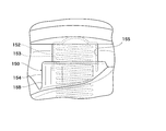
- Example 1 The operability of the check valve shown in FIG. 7 was evaluated in the same manner as in Example 1.
- the valve seat (not shown), the valve body 152 and the biasing means 153 of the check valve 150 shown in FIG. 7 are the same as those of the check valve 50 shown in FIG.
- the check valve 150 shown in FIG. 7 is different from the check valve 50 shown in FIG. 2 in the shape of the guide portion 154 and the shape of the opening portion 155 provided in the guide portion 154. That is, the check valve 50 shown in FIG. 2 has the third opening 59 in the support portion 58, whereas the check valve 50 shown in FIG. Surrounds and does not have an opening.
- valve body 2 has the first opening 55a and the second opening 55b in which the circumferential lengths of the valve bodies 52 are different from each other, whereas the check valve 150 shown in FIG.
- the circumferential length of the valve body 152 is constant throughout the central axis O direction of the valve body 152.
- Example 1 and Example 2 were As shown in FIG. 6, in Example 1, the ratio of the amount of change in the opening area of the opening to the amount of change in the separation distance changed stepwise from small to large. On the other hand, in Comparative Example 1, the ratio of the change amount of the opening area of the opening to the change amount of the separation distance was constant (not shown).
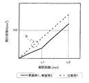
- FIG. 8 is a graph showing the relationship between the separation distance and the opening area.
- the contact surface of the valve body is in the first opening before the separation distance L1
- the contact surface of the valve body is in the second opening after the separation distance L1.
- the separation distance L ⁇ b> 2 indicates the separation distance when the check valves of Examples 1 and 2 and Comparative Example 1 are fully opened.
- an opening area A0 indicates the area of the suction port formed by the valve seat.
- Example 1 and Example 2 change greatly before and after the separation distance L1, whereas the slope of Comparative Example 1 is constant.
- the inclination after the separation distance L1 of Example 1 and Example 2 was almost the same as the inclination of Comparative Example 1.
- a region S surrounded by a one-dotted line in FIG. 8 is a region where the valve body of Comparative Example 1 is caught in the middle of the opening in the opening / closing operation confirmation test.
- the opening area of Comparative Example 1 is smaller than the area A0 of the suction port formed by the valve seat. For this reason, when the valve body is caught in the middle of the opening as in the open / close operation confirmation test of Comparative Example 1, a sufficient opening area cannot be secured, the passage resistance increases, and the performance of the compressor decreases. Is predicted.
- the opening area at the separation distance L2 when fully opened in Example 1 and Example 2 is smaller than that in Comparative Example 1, but larger than the area A0 of the suction port formed by the valve seat.
- the check valve shown in FIG. 2 to FIG. 5 is sufficient to open the check valve fully without causing the valve body to be caught in the opening as in the open / close operation confirmation test of the first and second embodiments. An opening area can be ensured, and passage resistance does not increase.
Landscapes
- Engineering & Computer Science (AREA)
- General Engineering & Computer Science (AREA)
- Mechanical Engineering (AREA)
- Rotary Pumps (AREA)
- Applications Or Details Of Rotary Compressors (AREA)
Abstract
【課題】本発明の目的は、逆止弁の動作性を向上させたベーン型圧縮機を提供することである。 【解決手段】本発明に係るベーン型圧縮機1は、冷媒ガスを吸入する吸入ポート12と吸入ポート12に連通する低圧室13とを有するハウジングと、低圧室での冷媒ガスの逆流を防止する逆止弁50と、を備えるベーン型圧縮機において、逆止弁は、吸入ポート内に設けられた弁座51と、弁座に当接する当接部521bを有する筒状の弁体52と、弁体を弁座に当接させる付勢部材53と、ハウジングと一体に形成され、弁体をスライド自在に収容するガイド部54とを有し、ガイド部は、周壁の一部を低圧室に開口させた開口部55を有し、弁体の周面部522がガイド部の内壁に沿ってスライドすることで、開口部の開口面積が変化し、弁座に対する弁体の離間距離の増加にしたがって、離間距離の変化量に対する開口部の開口面積の変化量の割合が小から大に段階的に変化する。
Description
本発明は、ベーン型圧縮機に関し、特には、逆止弁の動作性を向上させたベーン型圧縮機に関する。
車両用空調装置用のベーン型圧縮機において、圧縮機の低圧室から外部冷凍サイクルへの冷媒ガスの逆流を防止するために、圧縮機の吸入ポート近傍に逆止弁を設ける構造が知られている。この構造によれば、圧縮機運転中は逆止弁が開き、外部冷凍サイクルから吸入された低圧冷媒が吸入ポートから低圧室内に吸入される。また圧縮機停止時は逆止弁が閉じることにより、圧縮過程にある圧縮室内の冷媒が圧縮機構を逆転させて吸入ポートから冷却用熱交換器側外部冷凍サイクルに逆流することを抑制している。
逆止弁の構成として、ガイド筒(弁ケース)、付勢手段(スプリング)、弁体及び弁座が、フロントヘッドに形成された吸入ポートに挿入され、弁体が弁ケースにより姿勢制御される構成が開示されている(例えば、特許文献1を参照。)。しかし、弁ケースを有する逆止弁では、弁ケースをフロントヘッドに固定する時に弁ケースが変形するおそれがあった。そこで、弁ケースをフロントヘッドに一体化させた逆止弁が提案されている(例えば、特許文献2~4を参照。)。
しかし、特許文献2の逆止弁では、弁体がガイド部によって片持ち支持されるため、弁体が傾斜してガス通路を形成する開口に引っかかり、逆止弁の動作性が妨げられる問題があった。また、特許文献3の逆止弁では、特許文献2の逆止弁に比べて弁体の開口への引っかかりは解消されているが、開口部が複数に分断されているため、冷媒ガスのための有効な通路が狭くなり、相対的に通路抵抗が大きくなりがちである。また、圧縮機の運転開始とともにすみやかに逆止弁を全開にさせる工夫はされていない。特許文献4の逆止弁では、特許文献2の逆止弁に比べて弁体に対する押上げ力の発生は解消されているが、圧縮機の運転開始とともにすみやかに逆止弁を全開にさせる工夫はされていない。これまで、弁ケースをフロントヘッドに一体化させた逆止弁に関し、圧縮機の運転開始とともにすみやかに弁体をガイド部の底面まで押し下げて、逆止弁を全開にすることができる逆止弁構造は開示されていない。
本発明の目的は、弁ケースをフロントヘッドに一体化させた逆止弁に関し、逆止弁の通路抵抗を低減させるために、逆止弁の動作性を向上させたベーン型圧縮機を提供することである。
本発明に係るベーン型圧縮機は、外部冷凍サイクルから冷媒ガスを吸入する吸入ポートと該吸入ポートに連通する低圧室とを有するハウジングと、前記低圧室から前記外部冷凍サイクルへの前記冷媒ガスの逆流を防止する逆止弁と、を備えるベーン型圧縮機において、前記逆止弁は、前記吸入ポート内に設けられ、中央に吸入口が形成された弁座と、該弁座に当接する当接部を有する筒状の弁体と、該弁体を前記弁座に当接させる方向に付勢する付勢部材と、前記ハウジングと一体に形成され、前記弁体をスライド自在に収容するガイド部と、を有し、該ガイド部は、周壁の一部を前記低圧室に開口させた開口部を有し、前記弁体の周面部が前記ガイド部の内壁に沿ってスライドすることで、前記開口部の開口面積が変化し、前記弁座に対する前記弁体の離間距離の増加にしたがって、前記離間距離の変化量に対する前記開口部の開口面積の変化量の割合が小から大に段階的に変化することを特徴とする。
本発明に係るベーン型圧縮機では、前記離間距離の変化量に対する前記開口面積の変化量の割合が小であるときの前記開口面積の最大値は、前記弁座が形成する吸入口の面積よりも小さいことが好ましい。これによって、吸入口を通過する圧力降下(圧力損失ともいう。)に比して開口部を通過する圧力降下が相対的に大きくなるようにし、弁体の上流側に作用する圧力を相対的に高めることができる。その結果、圧縮機の運転開始とともにすみやかに弁体をガイド部の底面まで押し下げて、逆止弁を全開にすることができる。
本発明に係るベーン型圧縮機では、前記開口部は、前記吸入ポート側から順に、第1開口部と、該第1開口部に連接し、該第1開口部よりも前記弁体の周方向の開口間隔が広い第2開口部とを有することが好ましい。これによって、離間距離の変化量に対する開口部の開口面積の変化量の割合を小から大に段階的に変化させることができる。
本発明に係るベーン型圧縮機では、前記ガイド部は、前記弁体の傾きを抑制するように該弁体の周面部を支持する支持部を有し、該支持部は、前記弁体の前記当接部が前記第2開口部内にあるとき、前記弁体の周面部の高さの1/2以上を支持することが好ましい。これによって、弁体の傾きをより抑制することができる。その結果、逆止弁の動作性をより向上させることができる。
本発明に係るベーン型圧縮機では、前記弁体の当接部が前記離間距離の変化量に対する前記開口面積の変化量の割合が小である前記離間距離の位置にあるとき、前記弁体の中心軸に直交し、かつ、前記当接部に接する断面において、前記開口部の一端と、前記弁体の中心軸と、前記開口部の他端とを結んで得られる角度は、120°未満であることが好ましい。これによって、弁体の傾きをより抑制して、逆止弁の動作性をより向上させることができる。
本発明に係るベーン型圧縮機では、前記開口部は、ロータの回転軸方向に平行な方向に開口していることが好ましい。これによって、吸入ポートから圧縮室への冷媒ガスの流入経路が短縮されるため、冷媒ガスの流れ抵抗を低減することができる。その結果、低圧冷媒をスムーズに圧縮機構側に流すことができる。
本発明に係るベーン型圧縮機では、前記弁体は、前記周面部と前記当接部との境界がR形状を有するように形成されていることが好ましい。これによって、弁体が開口部に引っかかりにくくなり、逆止弁の動作性をより向上させることができる。
本発明に係るベーン型圧縮機では、前記ガイド部は、前記吸入ポート側とは反対側の端部で、前記ガイド部の周壁の内周面を拡径させた環状の冷媒流通溝を有することが好ましい。これによって、ガイド部の底部に流れ込んだ冷媒ガスが冷媒流通溝を通るため、弁体の筒内でのガスの滞留を低減させて、弁体をガイド部の底面まで押し下げることができる。
本発明に係るベーン型圧縮機では、前記支持部には、前記第2開口部に連接する第3開口部が設けられていることが好ましい。これによって、冷媒ガスの流れ抵抗を低減することができる。また、弁体の筒内でのガスの滞留を低減させて、弁体をガイド部の底面まで押し下げることができる。さらに、弁体を押し下げた状態を保持することができる。また、弁体の中心軸方向における冷媒ガスの流量を増やすことができる。
本発明に係るベーン型圧縮機では、前記第3開口部の前記第2開口部側とは反対側の端部は、前記弁体の中心軸方向に直交する方向に対して傾斜していることが好ましい。これによって、潤滑オイル又は冷媒ガスのガイド部からの排出性を向上することができる。また、弁体の下端が第3開口部の端部に引っかかりにくく、弁体が下方に移動しやすくなる。
本発明は、弁ケースをフロントヘッドに一体化させた逆止弁に関し、逆止弁の通路抵抗を低減させるために、逆止弁の動作性を向上させたベーン型圧縮機を提供することができる。
以下、添付の図面を参照して本発明の一態様を説明する。以下に説明する実施形態は本発明の実施例であり、本発明は、以下の実施形態に制限されるものではない。なお、本明細書及び図面において符号が同じ構成要素は、相互に同一のものを示すものとする。本発明の効果を奏する限り、種々の形態変更をしてもよい。
本実施形態に係るベーン型圧縮機1は、図1に示すように、外部冷凍サイクル(不図示)から冷媒ガスを吸入する吸入ポート12と吸入ポート12に連通する低圧室13とを有するハウジング10と、低圧室13から外部冷凍サイクルへの冷媒ガスの逆流を防止する逆止弁50と、を備えるベーン型圧縮機において、逆止弁50は、図2~図4に示すように、吸入ポート12内に設けられ、中央に吸入口51aが形成された弁座51と、弁座51に当接する当接部521bを有する筒状の弁体52と、弁体52を弁座に当接させる方向に付勢する付勢部材53と、ハウジング10と一体に形成され、弁体52をスライド自在に収容するガイド部54と、を有し、ガイド部54は、周壁の一部を低圧室13に開口させた開口部55を有し、弁体の周面部522がガイド部54の内壁に沿ってスライドすることで、開口部55の開口面積Aが変化し、図6に示すように、弁座51に対する弁体52の離間距離Lの増加にしたがって、離間距離Lの変化量に対する開口部55の開口面積Aの変化量の割合が小から大に段階的に変化する。
ベーン型圧縮機1は、冷凍サイクル(不図示)の一部であり、冷却用熱交換器(不図示)で気化された冷媒ガスを圧縮して、高温・高圧になったガスを凝縮機(不図示)に送る。ベーン型圧縮機1について、図1を参照しながら簡単に説明する。本発明では、ベーン型圧縮機1は、逆止弁50以外の基本的な構造は特に限定されない。
ハウジング10は、カムリング2のリア側端面に固定されるリアヘッド7と、カムリング2のフロント側端面及び外周面を包囲し、リアヘッド7に嵌合するフロントヘッド8とを有する。
吸入ポート12は、フロントヘッド8と一体に形成された略円筒状の開口であり、冷却用熱交換器(不図示)で気化された冷媒ガスを吸入する。低圧室13は、フロントヘッド8内に形成された空間であって、吸入ポート12に連通する。また、リアヘッド7には、冷媒ガスを吐出する吐出ポート14と、吐出ポート14に連通する高圧室15とが設けられる。
ハウジング10内には、例えば、カムリング2と、カムリング2に回転可能に収納されるとともに回転軸3に固定されたロータ4と、が配置される。ロータ4には、複数のベーン溝5が設けられ、各ベーン溝5にはベーン6が挿入される。カムリング2の内周面には、楕円状の空間9が形成され、この空間9に真円状のロータ4が配置されることで、カムリング2の内周面とロータ4の外周面との間には圧縮空間16が形成される。圧縮空間16は、ベーン6によって仕切られて複数の圧縮室17を形成する。各圧縮室17の容積はロータ4の回転によって変化するようになっている。
逆止弁50は、図1に示すように、吸入ポート12と低圧室13との境界部に配置される。次に、図2~図6を参照しながら逆止弁50について説明する。
逆止弁50は、図2に示すように、弁座51と、弁体52と、付勢部材53と、ガイド部54と、を有する。
弁座51は、中央に吸入口51aが形成された環状部材であり、吸入ポート12内に圧入されて固定される。
弁体52は、閉塞部521と閉塞部521の周縁から下垂する周面部522とを有する筒状部材である。閉塞部521は、閉塞部521の中央を山形に突出させた突出部521aと、突出部521aの周囲に設けられた平坦状の当接部521bとを有する。本実施形態に係るベーン型圧縮機では、弁体の周面部522と当接部521bとの境界は、R形状を有するように形成されていることが好ましい。これによって、弁体52が開口部55に引っかかりにくくなり、逆止弁50の動作性をより向上させることができる。Rの範囲は特に限定されないが、例えば、R1mm~R2mmであることが好ましい。
付勢部材53は、例えばコイルスプリングであり、弁体52の筒内に挿入される。
ガイド部54は、フロントヘッド8の内側に一体に形成される。ガイド部54の内部空間には弁体52がスライド自在に収容される。ガイド部54の底面には、シャフトシール室19に連通する穴54aが設けられていてもよい。
本実施形態に係るベーン型圧縮機では、ガイド部54は、図2に示すように、吸入ポート12側とは反対側の端部で、ガイド部54の周壁の内周面を拡径させた環状の冷媒流通溝56を有することが好ましい。図5は、ガイド部の断面形状の一例であり、(a)は図4のA-A線断面図、(b)は図4のB-B線断面図、(c)は図4のC-C線断面図、(d)は図4のD-D線断面図、(e)は図4のE-E線断面図を示す。図5では、弁体が当該断面に存在する場合の仮想外周面形状52Fを二点鎖線で示した。冷媒流通溝56を設けることで、図5(e)に示すように、ガイド部54の内周面と弁体の外周面52Fとの間に隙間が形成される。このため、ガイド部54の底部に流れ込んだ冷媒ガスが、冷媒流通溝56を通って低圧室13に流れる。その結果、弁体52の筒内でのガスの滞留を低減させて、弁体52をガイド部54の底面まで押し下げることができ、かつ、押し下げた状態を保持することができる。
ガイド部54は、図2に示すように、冷媒流通溝56に交差し、冷媒流通溝56と吸入ポート12とを連通させる縦溝57を更に有することが好ましい。縦溝57の数は、特に限定されず、1個であるか、又は2個以上であってもよい。図5(a)~(d)では一例として縦溝57が2個である形態を示した。冷媒流通溝56に加えて縦溝57を有することで、縦溝57、冷媒流通溝56及び低圧室13を順次通る冷媒ガスの流路が形成され、冷媒ガスの流量を増やすことができる。
開口部55は、図2に示すように、ガイド部54の周壁のうち低圧室13に面する周壁に形成された孔である。吸入ポート12は、開口部55によって低圧室13に連通される。本実施形態に係るベーン型圧縮機1では、図1に示すように、開口部55は、ロータ4の回転軸3方向に平行な方向に開口していることが好ましい。これによって、吸入ポート12から圧縮室17への冷媒ガスの流入経路が短縮されるため、冷媒ガスの流れ抵抗を低減することができる。その結果、冷媒ガスをスムーズに圧縮機構側に流すことができる。
また、開口部55が、弁体52の周方向に一つだけあることが好ましい。すなわち、開口部55が周壁で区画されていないことが好ましい。開口部55が弁体52の周方向に一つだけあることで、冷媒ガスを分断することなく一つの開口部55に集中させて流してスムーズに圧縮機構側に供給することができる。このため、開口部55が弁体52の周方向に複数ある場合と比較して、許容可能な圧力降下を開口部での圧力降下のみに割り当てて設定することができる。その結果、弁体52をガイド部54の底面に向けてすみやかに押し下げて、逆止弁50を全開にすることができる。本明細書において、弁体52の周方向とは、弁体の周面部522の周方向をいう。
開口部55は、図3に示すように、ロータ4の回転軸3方向に平行な方向に開口し、かつ、弁体52の周方向に一つだけあることがより好ましい。
開口部55の開口面積A[mm2]は、弁体の周面部522がガイド部54の内壁に沿ってスライドすることで変化する。弁体の当接部521bが図3に示すように弁座51に当接しているとき、弁座51の吸入口51aが弁体の当接部521bによって閉鎖されるとともに、開口部55の全体が弁体52によって塞がれており、開口面積Aは0である。弁体52が弁座51から離れる方向にリフトすると、吸入口51aが閉鎖状態から開放されるとともに、開口部55の一部が開放され、弁座51に対する弁体52の離間距離L[mm]の増加にしたがって開口面積Aは大きくなる。そして、弁体52が図4に示すようにガイド部54の底面に到達したとき、開口部55の全体が開放され、開口面積Aは最大となる。本明細書において、開口面積Aは、ガイド部54の内壁面を開口部55内に仮想的に延長させた仮想面の面積のうち、開口部55の開放されている部分の面積である。ガイド部54の内壁面が円筒状であるとき、仮想面は円筒の周面形状をなす。
図6は、離間距離の変化量に対する開口部の開口面積の変化量の割合の段階的な変化を説明するための概念図である。弁座51に対する弁体52の離間距離Lの増加にしたがって、離間距離Lの変化量に対する開口部55の開口面積Aの変化量の割合(以降、dA/dLということもある。)が小から大に段階的に変化する。dA/dLが段階的に変化するとは、図6に示すように、離間距離LをX軸に、dA/dLをY軸にとって作成したグラフ900が、段差901を有することをいう。図6に示すように、段差前のdA/dLは、段差後のdA/dLよりも小さい。本発明は、グラフ900の形状及び段差901の程度に制限されない。
本実施形態に係るベーン型圧縮機では、Lの変化量に対するAの変化量の割合が小であるときの開口面積Aの最大値は、弁座51が形成する吸入口51aの面積よりも小さいことが好ましい。これによって、吸入口51aを通過する冷媒ガスの圧力降下に比して開口部55を通過する圧力降下が相対的に大きくなり、弁体の上流側に作用する圧力を高めることができる。その結果、圧縮機の運転開始とともにすみやかに弁体52をガイド部54の底面まで押し下げて、逆止弁50を全開にすることができる。
本実施形態に係るベーン型圧縮機では、図3に示すように、開口部55は、吸入ポート12(図2に図示)側から順に、第1開口部55aと、第1開口部55aに連接し、第1開口部55aよりも弁体52の周方向の開口間隔が広い第2開口部55bとを有することが好ましい。これによって、Lの変化量に対するAの変化量の割合を小から大に段階的に変化させることができる。
圧縮機の起動によって吸入ポート12から冷媒が吸入されると、弁体52が弁座51から離れる方向にリフトする。リフト開始直後は、弁体の当接部521bが第1開口部55aにあり、Lの変化量に対するAの変化量の割合は相対的に小さい。このため、冷媒流量の増加に伴って弁体52の離間距離Lが増加しても開口面積Aが緩慢に増加し、弁体52の上流側の圧力が高められることとなる。その結果、高められた弁体52の上流側の圧力によって、弁体52をガイド部54の底面に向けて勢いをつけて押し下げて、逆止弁50が全開になることを助けることができる。また、逆止弁50の通路抵抗を低減させるためには、逆止弁50が全開時に十分な開口面積を確保する必要がある。例えば、逆止弁50が全開時における開口部55の開口面積が、弁座51が形成する吸入口51aの面積よりも大きいことが好ましい。ところが、図3において第2開口部55bの開口間隔を第1開口部55aの開口間隔まで狭めた形態を想定すると、開口部55の長さ(弁体52の中心軸O方向の長さ)を長くしなければ、逆止弁50の全開時の開口面積が相対的に小さくなって、逆止弁50の通路抵抗を十分に低減することができない。開口部55の長さを長くすると、弁体52のストローク長さが長くなり、弁体52をガイド部54の底面まで到達させることが難しくなる。また、圧縮機のハウジング10内に逆止弁50が収まりきらない場合がある。そこで、本実施形態では、開口部55が、第1開口部55aよりも弁体52の周方向の開口間隔が広い第2開口部55bを有することで、開口部55の長さを長くしなくても、逆止弁50が全開時に十分な開口面積を確保することができる。これによって、弁体52がガイド部54の底面まで達しやすくするとともに、十分な開口面積を確保して開口部での圧力降下を低減することができる。また、ガイド部54が第1開口部55aを有することで、弁体52が弁座51から離れた直後の弁体52の傾きを抑制することができる。ガイド部54が支持部58を有することで、弁体の当接部521bが第2開口部55bにあるときの弁体52の傾きをより抑制することができる。その結果、逆止弁50の動作性をより向上させることができる。
本実施形態に係るベーン型圧縮機では、ガイド部54は、弁体52の傾きを抑制するように弁体の周面部522を支持する支持部58を有し、この支持部58は、弁体の当接部521bが第2開口部55b内に位置しているとき、弁体の周面部522の高さの1/2以上を支持することが好ましい。これによって、弁体の傾きをより抑制することができる。その結果、逆止弁の動作性をより向上させることができる。
第1開口部55aは、図3に示すように、弁体52の周方向の長さを弁体52の中心軸O方向で一定とした形状を有することが好ましい。弁体52は、第1開口部55aが開口されたガイド部54の内壁によって、傾きを抑制されながらガイド部54内を上下動する。このとき、弁体52とガイド部54の内壁面との間にはクリアランスがあり、当該クリアランスの範囲内で弁体52は傾いて弁体の周面部522の一部が第1開口部55aの縁辺に接触する場合がある。第1開口部55aの周方向の長さが一定ではなく、例えば、第2開口部55bに向かうにしたがって広がる形状であったとすると、弁体52がクリアランスの範囲内で傾いたとき、弁体の周面部522の第1開口部55aの縁辺に対する接触箇所が、弁体52の上下動に伴って変化する。そうすると、弁体の周面部522の第1開口部55aの縁辺に対する摺動抵抗が大きくなって、弁体52の上下動が妨げられるおそれがある。これに対して、第1開口部55aの周方向の長さが一定であると、弁体52がクリアランスの範囲内で傾いたとしても、弁体の周面部522の第1開口部55aの縁辺に対する接触箇所が、弁体52の上下動に伴って変化しない。その結果、弁体の周面部522が第1開口部55aの縁辺と擦れたとしても摺動抵抗を受けにくく、弁体52を滑らかに作動させることができる。
本実施形態に係るベーン型圧縮機では、弁体の当接部521bがLの変化量に対するAの変化量の割合が小である離間距離Lの位置にあるとき(図4では弁体の当接部521bが第1開口部55a内にあるとき)、図5(b)に示すように、弁体52の中心軸Oに直交し、かつ、当接部521bに接する仮想平面において、開口部55aの一端と、弁体の中心軸Oと、開口部55aの他端とを結んで得られる角度θ1は、120°未満であることが好ましい。これによれば、弁体の当接部521bが第1開口部55aにあるとき、ガイド部54内において弁体52が傾いたとしても、弁体の当接部521b側が開口部55aの縁辺を超えて傾くことが抑制される。θ1は、開口部55aの両端と弁体の中心軸Oが形成する角度のうち、開口部55a側の角度である。θ1は90°以下であることがより好ましい。弁体52(図2に図示)が弁座51(図2に図示)から離れた直後は、弁体の周面部522のうち支持部58によって支持される長さが、弁体の周面部522の高さの1/2未満となり、弁体52が傾きやすく、弁体52が開口部55aに引っかかりやすい傾向にあるところ、θ1を前記範囲とすることで、弁体52の傾きをより抑制して、逆止弁の動作性をより向上させることができる。θ1の下限は、45°以上であることが好ましく、60°以上であることがより好ましい。
弁体の当接部521bがLの変化量に対するAの変化量の割合が大である離間距離Lの範囲内にあるとき(図4では弁体の当接部521bが第1開口部55b内にあるとき)、図5(c)に示すように、弁体52の中心軸Oに直交し、かつ、当接部521bに接する断面において、開口部55bの一端と、弁体の中心軸Oと、開口部55bの他端とを結んで得られる角度θ2は、120°以上300°以下であることが好ましく、150°以上240°以下であることが好ましい。θ2は、開口部55bの両端と弁体の中心軸Oが形成する角度のうち、開口部55b側の角度である。θ2を前記範囲とすることで、冷媒ガスの吸入効率を向上させることができる。
本実施形態に係るベーン型圧縮機では、図3及び図4に示すように、支持部58には、第2開口部55bに連接する第3開口部59が設けられていることが好ましい。図1及び図3から明らかなように、弁体の当接部521bが第1開口部55a内にあるとき、ガイド部54の内部空間は、第3開口部59を介して低圧室13に連通している。このため、弁体52が下方に移動する際、弁体52の下方の冷媒ガスを速やかに低圧室13に逃がし、弁体52の筒内でのガスの滞留を低減させて、弁体52をガイド部54の底面まで押し下げることができる。さらに、弁体52を押し下げた状態を保持することができる。また、弁体52の中心軸方向における冷媒ガスの流量を増やすことができる。
本実施形態では、図5(d)に示すように、弁体52の中心軸Oに直交する断面において、第3開口部59の一端と、弁体の中心軸Oと、第3開口部59aの他端とを結んで得られる角度θ3は、45°以上120°未満であることが好ましく、60°以上100°以下であることが好ましい。θ3は、第3開口部59の両端と弁体の中心軸Oが形成する角度のうち、第3開口部59側の角度である。θ3を前記範囲とすることで、支持部58の効果及び第3開口部59の効果をバランスよく両立することができる。
本実施形態に係るベーン型圧縮機では、図3及び図4に示すように、第3開口部59の第2開口部55b側とは反対側の端部59aは、弁体52の中心軸O方向に直交する方向に対して傾斜していることが好ましい。これによって、潤滑オイル又は冷媒ガスのガイド部54からの排出性を向上することができる。また、弁体52の下端が第3開口部の端部59aに引っかかりにくく、弁体52が下方に移動しやすくなる。
図1を参照しながら、逆止弁50の動作を説明する。圧縮機が起動し、冷却用熱交換器(不図示)の出口から吸入ポート12に冷媒ガスが吸入されると、弁体52が弁座51から離れる方向にリフトし、冷媒ガスが吸入ポート12から低圧室13へ流入する。このとき、離間距離が少ない領域では開口部55の面積を狭めているため、開口部55を通過する圧力降下が大きくなり、弁体52に作用する圧力差を瞬間的に高くすることができる。その結果、弁体52はすみやかにガイド部54の底面まで押し下げられて、逆止弁50を全開にすることができる。また、吸入ポート12への冷媒ガスの流入量が少なくなると、付勢手段の付勢力によって弁体52が弁座51に押し付けられ、低圧室13から吸入ポート12への冷媒ガスの逆流を防止する。
以下、実施例に基づき本発明をさらに詳細に説明するが、本発明は、かかる実施例に何ら限定されるものではない。
(実施例1,2)
図2~図5に示す逆止弁の動作性を評価した。圧縮機のハウジング10に逆止弁50(スプリング53、弁体52及び弁座51)を装着した。弁体とガイド部とのクリアランス影響を確認するため、弁体とガイド部とのクリアランスを0.45mmとしたクリアランス大品(実施例1)、弁体とガイド部とのクリアランスを0.25mmとしたクリアランス小品(実施例2)の2種を用意した。その他の部品については逆止弁の動作を目視で確認するために組付けなかった。動作性の評価は、次の通り行った。すなわち、ハウジング10の吸入ポート12に、空気圧供給源(0.3~0.6MPa)をボールバルブを介して取り付けた。ボールバルブを断続的に繰り返して開閉(約1秒間隔)して逆止弁の上流に空気圧を供給し、逆止弁の弁体の動作性を目視で確認した。
図2~図5に示す逆止弁の動作性を評価した。圧縮機のハウジング10に逆止弁50(スプリング53、弁体52及び弁座51)を装着した。弁体とガイド部とのクリアランス影響を確認するため、弁体とガイド部とのクリアランスを0.45mmとしたクリアランス大品(実施例1)、弁体とガイド部とのクリアランスを0.25mmとしたクリアランス小品(実施例2)の2種を用意した。その他の部品については逆止弁の動作を目視で確認するために組付けなかった。動作性の評価は、次の通り行った。すなわち、ハウジング10の吸入ポート12に、空気圧供給源(0.3~0.6MPa)をボールバルブを介して取り付けた。ボールバルブを断続的に繰り返して開閉(約1秒間隔)して逆止弁の上流に空気圧を供給し、逆止弁の弁体の動作性を目視で確認した。
(比較例1)
図7に示す逆止弁の動作性を実施例1と同様の方法で評価した。図7に示す逆止弁150の弁座(不図示)、弁体152及び付勢手段153は、図2に示す逆止弁50のそれらと同じである。図7に示す逆止弁150が、図2に示す逆止弁50と相違する点は、ガイド部154の形状及びガイド部154に設けられた開口部155の形状である。すなわち、図2に示す逆止弁50が支持部58に第3開口部59を有するのに対して、図7に示す逆止弁50は支持部158が弁体152の周方向の全周を取り囲んでおり、開口部を有さない。図2に示す逆止弁50が、弁体52の周方向の長さが相互に異なる第1開口部55a及び第2開口部55bを有するのに対して、図7に示す逆止弁150は、弁体152の中心軸O方向の全体にわたって弁体152の周方向の長さが一定である。
図7に示す逆止弁の動作性を実施例1と同様の方法で評価した。図7に示す逆止弁150の弁座(不図示)、弁体152及び付勢手段153は、図2に示す逆止弁50のそれらと同じである。図7に示す逆止弁150が、図2に示す逆止弁50と相違する点は、ガイド部154の形状及びガイド部154に設けられた開口部155の形状である。すなわち、図2に示す逆止弁50が支持部58に第3開口部59を有するのに対して、図7に示す逆止弁50は支持部158が弁体152の周方向の全周を取り囲んでおり、開口部を有さない。図2に示す逆止弁50が、弁体52の周方向の長さが相互に異なる第1開口部55a及び第2開口部55bを有するのに対して、図7に示す逆止弁150は、弁体152の中心軸O方向の全体にわたって弁体152の周方向の長さが一定である。
(評価結果)
クリアランス大品(実施例1)及びクリアランス小品(実施例2)は、ともに20回の開閉動作確認試験において、一度も開口部に引っかかることがなかった。また、弁体がガイド部の底面まで瞬時に下がって、逆止弁を全開にすることができた。一方、比較例1の逆止弁は、20回の開閉動作確認試験において、開口部の途中で弁体が引っかかる現象が16回確認された。また、弁体をガイド部の底面まで下げる速度が、実施例1よりも遅いことがあった。
クリアランス大品(実施例1)及びクリアランス小品(実施例2)は、ともに20回の開閉動作確認試験において、一度も開口部に引っかかることがなかった。また、弁体がガイド部の底面まで瞬時に下がって、逆止弁を全開にすることができた。一方、比較例1の逆止弁は、20回の開閉動作確認試験において、開口部の途中で弁体が引っかかる現象が16回確認された。また、弁体をガイド部の底面まで下げる速度が、実施例1よりも遅いことがあった。
実施例1、実施例2及び比較例1について、離間距離と、離間距離の変化量に対する開口部の開口面積の変化量の割合との関係を確認したところ、実施例1及び実施例2は、図6に示すように、実施例1は、離間距離の変化量に対する開口部の開口面積の変化量の割合が小から大に段階的に変化した。一方、比較例1は、離間距離の変化量に対する開口部の開口面積の変化量の割合が一定であった(不図示)。
実施例1、実施例2及び比較例1について、離間距離と開口面積との関係を確認した。図8は、離間距離と開口面積との関係を示すグラフである。図8の実施例1及び実施例2において、離間距離L1前は、弁体の当接面が第1開口部内にあり、離間距離L1後は、弁体の当接面が第2開口部内にあることを示す。図8において離間距離L2は、実施例1、2及び比較例1の逆止弁の全開時の離間距離を示す。また、図8において開口面積A0は、弁座が形成する吸入口の面積を示す。
図8に示すように、実施例1及び実施例2は、離間距離L1の前後で傾きが大きく変化するのに対して、比較例1は、傾きが一定であった。実施例1及び実施例2の離間距離L1後の傾きは、比較例1の傾きとほぼ同じであった。
また、図8において一点差線で囲った領域Sは、開閉動作確認試験において比較例1の弁体が開口部の途中で引っかかった領域である。この領域Sでは、比較例1の開口面積は弁座が形成する吸入口の面積A0よりも小さい。このため、比較例1の開閉動作確認試験のように、弁体が開口部の途中で引っかかると、十分な開口面積が確保できず、通路抵抗が増大して、圧縮機の性能が低下することが予測される。これに対して、実施例1及び実施例2の全開時の離間距離L2における開口面積は、比較例1のそれよりも小さいが、弁座が形成する吸入口の面積A0よりも大きい。そして、図2~図5に示す逆止弁は、実施例1及び実施例2の開閉動作確認試験のように、弁体が開口部に引っかかることなく逆止弁を全開状態にして、十分な開口面積を確保することができ、通路抵抗が増大することがない。
1 ベーン型圧縮機
2 カムリング
3 回転軸
4 ロータ
5 ベーン溝
6 ベーン
7 リアヘッド
8 フロントヘッド
9 空間
10 ハウジング
12 吸入ポート
13 低圧室
14 吐出ポート
15 高圧室
16 圧縮空間
17 圧縮室
18 シャフトシール
19 シャフトシール室
50 逆止弁
51 弁座
51a 吸入口
52 弁体
52F 弁体の外周面形状
53 付勢部材
54 ガイド部
54a 穴
55 開口部
55a 第1開口部
55b 第2開口部
56 冷媒流通溝
57 縦溝
58 支持部
59 第3開口部
59a 第3開口部の端部
150 逆止弁
152 弁体
153 付勢手段
154 ガイド部
155 開口部
158 支持部
521 閉塞部
521a 突出部
521b 当接部
522 周面部
900 グラフ
901 段差
Claims (10)
- 外部冷凍サイクルから冷媒ガスを吸入する吸入ポートと該吸入ポートに連通する低圧室とを有するハウジングと、前記低圧室から前記外部冷凍サイクルへの前記冷媒ガスの逆流を防止する逆止弁と、を備えるベーン型圧縮機において、
前記逆止弁は、
前記吸入ポート内に設けられ、中央に吸入口が形成された弁座と、
該弁座に当接する当接部を有する筒状の弁体と、
該弁体を前記弁座に当接させる方向に付勢する付勢部材と、
前記ハウジングと一体に形成され、前記弁体をスライド自在に収容するガイド部と、を有し、
該ガイド部は、周壁の一部を前記低圧室に開口させた開口部を有し、
前記弁体の周面部が前記ガイド部の内壁に沿ってスライドすることで、前記開口部の開口面積が変化し、
前記弁座に対する前記弁体の離間距離の増加にしたがって、前記離間距離の変化量に対する前記開口部の開口面積の変化量の割合が小から大に段階的に変化することを特徴とするベーン型圧縮機。 - 前記離間距離の変化量に対する前記開口面積の変化量の割合が小であるときの前記開口面積の最大値は、前記弁座が形成する吸入口の面積よりも小さいことを特徴とする請求項1に記載のベーン型圧縮機。
- 前記開口部は、前記吸入ポート側から順に、第1開口部と、該第1開口部に連接し、該第1開口部よりも前記弁体の周方向の開口間隔が広い第2開口部とを有することを特徴とする請求項1又は2に記載のベーン型圧縮機。
- 前記ガイド部は、前記弁体の傾きを抑制するように該弁体の周面部を支持する支持部を有し、
該支持部は、前記弁体の前記当接部が前記第2開口部内にあるとき、前記弁体の周面部の高さの1/2以上を支持することを特徴とする請求項3に記載のベーン型圧縮機。 - 前記弁体の当接部が前記離間距離の変化量に対する前記開口面積の変化量の割合が小である前記離間距離の位置にあるとき、前記弁体の中心軸に直交し、かつ、前記当接部に接する断面において、前記開口部の一端と、前記弁体の中心軸と、前記開口部の他端とを結んで得られる角度は、120°未満であることを特徴とする請求項1~4のいずれか一つに記載のベーン型圧縮機。
- 前記開口部は、ロータの回転軸方向に平行な方向に開口していることを特徴とする請求項1~5のいずれか一つに記載のベーン型圧縮機。
- 前記弁体は、前記周面部と前記当接部との境界がR形状を有するよう形成されていることを特徴とする請求項1~6のいずれか一つに記載のベーン型圧縮機。
- 前記ガイド部は、前記吸入ポート側とは反対側の端部で、前記ガイド部の周壁の内周面を拡径させた環状の冷媒流通溝を有することを特徴とする請求項1~7のいずれか一つに記載のベーン型圧縮機。
- 前記支持部には、前記第2開口部に連接する第3開口部が設けられていることを特徴とする請求項3に記載のベーン型圧縮機。
- 前記第3開口部の前記第2開口部側とは反対側の端部は、前記弁体の中心軸方向に直交する方向に対して傾斜していることを特徴とする請求項9に記載のベーン型圧縮機。
Priority Applications (2)
| Application Number | Priority Date | Filing Date | Title |
|---|---|---|---|
| EP16772526.6A EP3293396B1 (en) | 2015-03-27 | 2016-03-24 | Vane compressor |
| JP2017509857A JP6472870B2 (ja) | 2015-03-27 | 2016-03-24 | ベーン型圧縮機 |
Applications Claiming Priority (2)
| Application Number | Priority Date | Filing Date | Title |
|---|---|---|---|
| JP2015-065797 | 2015-03-27 | ||
| JP2015065797 | 2015-03-27 |
Publications (1)
| Publication Number | Publication Date |
|---|---|
| WO2016158645A1 true WO2016158645A1 (ja) | 2016-10-06 |
Family
ID=57004300
Family Applications (1)
| Application Number | Title | Priority Date | Filing Date |
|---|---|---|---|
| PCT/JP2016/059318 Ceased WO2016158645A1 (ja) | 2015-03-27 | 2016-03-24 | ベーン型圧縮機 |
Country Status (3)
| Country | Link |
|---|---|
| EP (1) | EP3293396B1 (ja) |
| JP (1) | JP6472870B2 (ja) |
| WO (1) | WO2016158645A1 (ja) |
Cited By (1)
| Publication number | Priority date | Publication date | Assignee | Title |
|---|---|---|---|---|
| CN109372753A (zh) * | 2018-12-10 | 2019-02-22 | 珠海格力节能环保制冷技术研究中心有限公司 | 止回阀组件、压缩机及空调器 |
Citations (4)
| Publication number | Priority date | Publication date | Assignee | Title |
|---|---|---|---|---|
| JPH05288186A (ja) * | 1992-04-06 | 1993-11-02 | Zexel Corp | 圧縮機の吸入弁 |
| JP2004353620A (ja) * | 2003-05-30 | 2004-12-16 | Calsonic Compressor Seizo Kk | 気体圧縮機及び該気体圧縮機の製造方法 |
| JP2006125374A (ja) * | 2004-11-01 | 2006-05-18 | Calsonic Kansei Corp | 吐出側構造及びこれに用いる逆止弁、並びにこれらを用いた圧縮機 |
| JP2014227901A (ja) * | 2013-05-22 | 2014-12-08 | カルソニックカンセイ株式会社 | 気体圧縮機 |
Family Cites Families (3)
| Publication number | Priority date | Publication date | Assignee | Title |
|---|---|---|---|---|
| JP2000346217A (ja) * | 1999-06-07 | 2000-12-15 | Toyota Autom Loom Works Ltd | 逆止弁 |
| JP4429931B2 (ja) * | 2005-02-07 | 2010-03-10 | サンデン株式会社 | 開度調整弁 |
| JP4879713B2 (ja) * | 2006-11-20 | 2012-02-22 | 太平洋工業株式会社 | チェックバルブ |
-
2016
- 2016-03-24 WO PCT/JP2016/059318 patent/WO2016158645A1/ja not_active Ceased
- 2016-03-24 JP JP2017509857A patent/JP6472870B2/ja active Active
- 2016-03-24 EP EP16772526.6A patent/EP3293396B1/en active Active
Patent Citations (4)
| Publication number | Priority date | Publication date | Assignee | Title |
|---|---|---|---|---|
| JPH05288186A (ja) * | 1992-04-06 | 1993-11-02 | Zexel Corp | 圧縮機の吸入弁 |
| JP2004353620A (ja) * | 2003-05-30 | 2004-12-16 | Calsonic Compressor Seizo Kk | 気体圧縮機及び該気体圧縮機の製造方法 |
| JP2006125374A (ja) * | 2004-11-01 | 2006-05-18 | Calsonic Kansei Corp | 吐出側構造及びこれに用いる逆止弁、並びにこれらを用いた圧縮機 |
| JP2014227901A (ja) * | 2013-05-22 | 2014-12-08 | カルソニックカンセイ株式会社 | 気体圧縮機 |
Non-Patent Citations (1)
| Title |
|---|
| See also references of EP3293396A4 * |
Cited By (2)
| Publication number | Priority date | Publication date | Assignee | Title |
|---|---|---|---|---|
| CN109372753A (zh) * | 2018-12-10 | 2019-02-22 | 珠海格力节能环保制冷技术研究中心有限公司 | 止回阀组件、压缩机及空调器 |
| CN109372753B (zh) * | 2018-12-10 | 2023-10-03 | 珠海格力节能环保制冷技术研究中心有限公司 | 止回阀组件、压缩机及空调器 |
Also Published As
| Publication number | Publication date |
|---|---|
| EP3293396A1 (en) | 2018-03-14 |
| JPWO2016158645A1 (ja) | 2017-12-14 |
| EP3293396A4 (en) | 2019-01-16 |
| JP6472870B2 (ja) | 2019-02-20 |
| EP3293396B1 (en) | 2021-05-05 |
Similar Documents
| Publication | Publication Date | Title |
|---|---|---|
| EP2924299B1 (en) | Centrifugal compressor | |
| CN1854525B (zh) | 涡旋机 | |
| CN102141038A (zh) | 叶片泵 | |
| KR20110058017A (ko) | 가변용량형 사판식 압축기 | |
| WO2014017081A1 (ja) | 圧縮機 | |
| CN109477470B (zh) | 斜盘式压缩机 | |
| WO2018083944A1 (ja) | 圧縮機 | |
| JP6472870B2 (ja) | ベーン型圧縮機 | |
| JP2007333131A (ja) | 差圧弁 | |
| JP5626260B2 (ja) | ベーン型圧縮機 | |
| WO2018110449A1 (ja) | 圧縮機の弁構造 | |
| KR101258342B1 (ko) | 가변 용량형 압축기용 제어밸브 | |
| KR20200009554A (ko) | 가변 용량 사판식 압축기 | |
| KR102073110B1 (ko) | 가변 사판식 압축기용 토출체크밸브 | |
| KR101370736B1 (ko) | 압축기용 제어밸브 | |
| JP6927123B2 (ja) | 圧縮機用のバネなし逆止弁 | |
| JP7062698B2 (ja) | 可変容量型圧縮機 | |
| WO2018062479A1 (ja) | 圧縮機の弁構造 | |
| CN103890391B (zh) | 用于压缩机的控制阀 | |
| KR102118600B1 (ko) | 압축기의 흡입 맥동 저감장치 | |
| JP4493480B2 (ja) | 可変容量斜板式圧縮機の容量制御弁 | |
| KR102080624B1 (ko) | 사판식 압축기 | |
| KR20130043380A (ko) | 압축기용 제어밸브 | |
| KR101205220B1 (ko) | 가변용량형 사판식 압축기 | |
| KR102524602B1 (ko) | 가변식 압축기용 체크 밸브 |
Legal Events
| Date | Code | Title | Description |
|---|---|---|---|
| 121 | Ep: the epo has been informed by wipo that ep was designated in this application |
Ref document number: 16772526 Country of ref document: EP Kind code of ref document: A1 |
|
| ENP | Entry into the national phase |
Ref document number: 2017509857 Country of ref document: JP Kind code of ref document: A |
|
| NENP | Non-entry into the national phase |
Ref country code: DE |
|
| WWE | Wipo information: entry into national phase |
Ref document number: 2016772526 Country of ref document: EP |