WO2016158765A1 - エンジン用圧縮機翼 - Google Patents
エンジン用圧縮機翼 Download PDFInfo
- Publication number
- WO2016158765A1 WO2016158765A1 PCT/JP2016/059656 JP2016059656W WO2016158765A1 WO 2016158765 A1 WO2016158765 A1 WO 2016158765A1 JP 2016059656 W JP2016059656 W JP 2016059656W WO 2016158765 A1 WO2016158765 A1 WO 2016158765A1
- Authority
- WO
- WIPO (PCT)
- Prior art keywords
- coating
- engine
- compressor blade
- blade
- compressor
- Prior art date
- Legal status (The legal status is an assumption and is not a legal conclusion. Google has not performed a legal analysis and makes no representation as to the accuracy of the status listed.)
- Ceased
Links
Images


Classifications
-
- F—MECHANICAL ENGINEERING; LIGHTING; HEATING; WEAPONS; BLASTING
- F04—POSITIVE - DISPLACEMENT MACHINES FOR LIQUIDS; PUMPS FOR LIQUIDS OR ELASTIC FLUIDS
- F04D—NON-POSITIVE-DISPLACEMENT PUMPS
- F04D29/00—Details, component parts, or accessories
- F04D29/02—Selection of particular materials
- F04D29/023—Selection of particular materials especially adapted for elastic fluid pumps
-
- F—MECHANICAL ENGINEERING; LIGHTING; HEATING; WEAPONS; BLASTING
- F01—MACHINES OR ENGINES IN GENERAL; ENGINE PLANTS IN GENERAL; STEAM ENGINES
- F01D—NON-POSITIVE DISPLACEMENT MACHINES OR ENGINES, e.g. STEAM TURBINES
- F01D5/00—Blades; Blade-carrying members; Heating, heat-insulating, cooling or antivibration means on the blades or the members
- F01D5/12—Blades
- F01D5/28—Selecting particular materials; Particular measures relating thereto; Measures against erosion or corrosion
- F01D5/288—Protective coatings for blades
-
- F—MECHANICAL ENGINEERING; LIGHTING; HEATING; WEAPONS; BLASTING
- F02—COMBUSTION ENGINES; HOT-GAS OR COMBUSTION-PRODUCT ENGINE PLANTS
- F02C—GAS-TURBINE PLANTS; AIR INTAKES FOR JET-PROPULSION PLANTS; CONTROLLING FUEL SUPPLY IN AIR-BREATHING JET-PROPULSION PLANTS
- F02C7/00—Features, components parts, details or accessories, not provided for in, or of interest apart form groups F02C1/00 - F02C6/00; Air intakes for jet-propulsion plants
- F02C7/30—Preventing corrosion or unwanted deposits in gas-swept spaces
-
- F—MECHANICAL ENGINEERING; LIGHTING; HEATING; WEAPONS; BLASTING
- F04—POSITIVE - DISPLACEMENT MACHINES FOR LIQUIDS; PUMPS FOR LIQUIDS OR ELASTIC FLUIDS
- F04D—NON-POSITIVE-DISPLACEMENT PUMPS
- F04D29/00—Details, component parts, or accessories
- F04D29/26—Rotors specially for elastic fluids
- F04D29/32—Rotors specially for elastic fluids for axial flow pumps
- F04D29/321—Rotors specially for elastic fluids for axial flow pumps for axial flow compressors
- F04D29/324—Blades
-
- F—MECHANICAL ENGINEERING; LIGHTING; HEATING; WEAPONS; BLASTING
- F04—POSITIVE - DISPLACEMENT MACHINES FOR LIQUIDS; PUMPS FOR LIQUIDS OR ELASTIC FLUIDS
- F04D—NON-POSITIVE-DISPLACEMENT PUMPS
- F04D29/00—Details, component parts, or accessories
- F04D29/40—Casings; Connections of working fluid
- F04D29/52—Casings; Connections of working fluid for axial pumps
- F04D29/54—Fluid-guiding means, e.g. diffusers
- F04D29/541—Specially adapted for elastic fluid pumps
- F04D29/542—Bladed diffusers
-
- F—MECHANICAL ENGINEERING; LIGHTING; HEATING; WEAPONS; BLASTING
- F04—POSITIVE - DISPLACEMENT MACHINES FOR LIQUIDS; PUMPS FOR LIQUIDS OR ELASTIC FLUIDS
- F04D—NON-POSITIVE-DISPLACEMENT PUMPS
- F04D29/00—Details, component parts, or accessories
- F04D29/70—Suction grids; Strainers; Dust separation; Cleaning
- F04D29/701—Suction grids; Strainers; Dust separation; Cleaning especially adapted for elastic fluid pumps
-
- F—MECHANICAL ENGINEERING; LIGHTING; HEATING; WEAPONS; BLASTING
- F05—INDEXING SCHEMES RELATING TO ENGINES OR PUMPS IN VARIOUS SUBCLASSES OF CLASSES F01-F04
- F05D—INDEXING SCHEME FOR ASPECTS RELATING TO NON-POSITIVE-DISPLACEMENT MACHINES OR ENGINES, GAS-TURBINES OR JET-PROPULSION PLANTS
- F05D2220/00—Application
- F05D2220/30—Application in turbines
- F05D2220/32—Application in turbines in gas turbines
- F05D2220/323—Application in turbines in gas turbines for aircraft propulsion, e.g. jet engines
-
- F—MECHANICAL ENGINEERING; LIGHTING; HEATING; WEAPONS; BLASTING
- F05—INDEXING SCHEMES RELATING TO ENGINES OR PUMPS IN VARIOUS SUBCLASSES OF CLASSES F01-F04
- F05D—INDEXING SCHEME FOR ASPECTS RELATING TO NON-POSITIVE-DISPLACEMENT MACHINES OR ENGINES, GAS-TURBINES OR JET-PROPULSION PLANTS
- F05D2240/00—Components
- F05D2240/10—Stators
- F05D2240/12—Fluid guiding means, e.g. vanes
-
- F—MECHANICAL ENGINEERING; LIGHTING; HEATING; WEAPONS; BLASTING
- F05—INDEXING SCHEMES RELATING TO ENGINES OR PUMPS IN VARIOUS SUBCLASSES OF CLASSES F01-F04
- F05D—INDEXING SCHEME FOR ASPECTS RELATING TO NON-POSITIVE-DISPLACEMENT MACHINES OR ENGINES, GAS-TURBINES OR JET-PROPULSION PLANTS
- F05D2240/00—Components
- F05D2240/20—Rotors
- F05D2240/30—Characteristics of rotor blades, i.e. of any element transforming dynamic fluid energy to or from rotational energy and being attached to a rotor
-
- F—MECHANICAL ENGINEERING; LIGHTING; HEATING; WEAPONS; BLASTING
- F05—INDEXING SCHEMES RELATING TO ENGINES OR PUMPS IN VARIOUS SUBCLASSES OF CLASSES F01-F04
- F05D—INDEXING SCHEME FOR ASPECTS RELATING TO NON-POSITIVE-DISPLACEMENT MACHINES OR ENGINES, GAS-TURBINES OR JET-PROPULSION PLANTS
- F05D2260/00—Function
- F05D2260/60—Fluid transfer
- F05D2260/607—Preventing clogging or obstruction of flow paths by dirt, dust, or foreign particles
-
- F—MECHANICAL ENGINEERING; LIGHTING; HEATING; WEAPONS; BLASTING
- F05—INDEXING SCHEMES RELATING TO ENGINES OR PUMPS IN VARIOUS SUBCLASSES OF CLASSES F01-F04
- F05D—INDEXING SCHEME FOR ASPECTS RELATING TO NON-POSITIVE-DISPLACEMENT MACHINES OR ENGINES, GAS-TURBINES OR JET-PROPULSION PLANTS
- F05D2300/00—Materials; Properties thereof
- F05D2300/10—Metals, alloys or intermetallic compounds
- F05D2300/13—Refractory metals, i.e. Ti, V, Cr, Zr, Nb, Mo, Hf, Ta, W
-
- F—MECHANICAL ENGINEERING; LIGHTING; HEATING; WEAPONS; BLASTING
- F05—INDEXING SCHEMES RELATING TO ENGINES OR PUMPS IN VARIOUS SUBCLASSES OF CLASSES F01-F04
- F05D—INDEXING SCHEME FOR ASPECTS RELATING TO NON-POSITIVE-DISPLACEMENT MACHINES OR ENGINES, GAS-TURBINES OR JET-PROPULSION PLANTS
- F05D2300/00—Materials; Properties thereof
- F05D2300/10—Metals, alloys or intermetallic compounds
- F05D2300/13—Refractory metals, i.e. Ti, V, Cr, Zr, Nb, Mo, Hf, Ta, W
- F05D2300/131—Molybdenum
-
- F—MECHANICAL ENGINEERING; LIGHTING; HEATING; WEAPONS; BLASTING
- F05—INDEXING SCHEMES RELATING TO ENGINES OR PUMPS IN VARIOUS SUBCLASSES OF CLASSES F01-F04
- F05D—INDEXING SCHEME FOR ASPECTS RELATING TO NON-POSITIVE-DISPLACEMENT MACHINES OR ENGINES, GAS-TURBINES OR JET-PROPULSION PLANTS
- F05D2300/00—Materials; Properties thereof
- F05D2300/20—Oxide or non-oxide ceramics
- F05D2300/22—Non-oxide ceramics
- F05D2300/229—Sulfides
- F05D2300/2291—Sulfides of molybdenum
-
- F—MECHANICAL ENGINEERING; LIGHTING; HEATING; WEAPONS; BLASTING
- F05—INDEXING SCHEMES RELATING TO ENGINES OR PUMPS IN VARIOUS SUBCLASSES OF CLASSES F01-F04
- F05D—INDEXING SCHEME FOR ASPECTS RELATING TO NON-POSITIVE-DISPLACEMENT MACHINES OR ENGINES, GAS-TURBINES OR JET-PROPULSION PLANTS
- F05D2300/00—Materials; Properties thereof
- F05D2300/30—Inorganic materials other than provided for in groups F05D2300/10 - F05D2300/2291
-
- F—MECHANICAL ENGINEERING; LIGHTING; HEATING; WEAPONS; BLASTING
- F05—INDEXING SCHEMES RELATING TO ENGINES OR PUMPS IN VARIOUS SUBCLASSES OF CLASSES F01-F04
- F05D—INDEXING SCHEME FOR ASPECTS RELATING TO NON-POSITIVE-DISPLACEMENT MACHINES OR ENGINES, GAS-TURBINES OR JET-PROPULSION PLANTS
- F05D2300/00—Materials; Properties thereof
- F05D2300/60—Properties or characteristics given to material by treatment or manufacturing
- F05D2300/611—Coating
-
- Y—GENERAL TAGGING OF NEW TECHNOLOGICAL DEVELOPMENTS; GENERAL TAGGING OF CROSS-SECTIONAL TECHNOLOGIES SPANNING OVER SEVERAL SECTIONS OF THE IPC; TECHNICAL SUBJECTS COVERED BY FORMER USPC CROSS-REFERENCE ART COLLECTIONS [XRACs] AND DIGESTS
- Y02—TECHNOLOGIES OR APPLICATIONS FOR MITIGATION OR ADAPTATION AGAINST CLIMATE CHANGE
- Y02T—CLIMATE CHANGE MITIGATION TECHNOLOGIES RELATED TO TRANSPORTATION
- Y02T50/00—Aeronautics or air transport
- Y02T50/60—Efficient propulsion technologies, e.g. for aircraft
Definitions
- the present disclosure relates to a compressor blade for an aircraft jet engine or a gas turbine engine, and more particularly, to a compressor blade capable of maintaining good aerodynamic characteristics due to spontaneous separation of deposits on the surface of the blade.
- a combustor In an aircraft jet engine or gas turbine engine, a combustor generates high-speed high-temperature gas, the turbine extracts energy from the high-temperature gas, and the compressor is driven with a part of the energy. The compressor sucks outside air, compresses it, and supplies it to the combustor. When air is compressed adiabatically in the compressor, a high temperature of, for example, about 400 to 700 ° C. is generated.
- the outside air contains various dusts, sand, and, in some cases, volcanic ash, which inevitably flows into the compressor. Some of these are exhausted with the compressed air through the combustor, but some are also attached to the compressor blades.
- the outside air also contains moisture, sulfate, sulfite, chloride, carbonate, etc. in the form of gas or fine droplets, which can also adhere to the compressor blades. These extraneous materials change physically and chemically when exposed to high temperatures, resulting in deposits that adhere to the blade surface.
- Patent Documents 1 and 2 disclose related techniques. These coating techniques attempt to prevent foreign substances from adhering.
- a compressor blade for an engine that is used in an environment containing abundant foreign substances is a base of the compressor blade and a coating that covers the base, and is composed of molybdenum disulfide and tungsten disulfide.
- the coating is limited to the blade surface and the platform portion, or the inner band portion and the outer band portion, and covers the entire surface.
- the compressor blade further includes an intermediate coating interposed between the coating and the base. More preferably, the coating film and the intermediate coating film form three or more sets of multilayer films alternately stacked. More preferably, the intermediate coating is made of one or more selected from the group consisting of titanium-aluminum nitride and chromium-aluminum nitride.
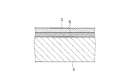
- FIG. 1 is a schematic cross-sectional view of a substrate and a coating according to one embodiment.
- FIG. 2 is a schematic cross-sectional view of a substrate and a coating according to another embodiment.
- FIG. 3 is a schematic cross-sectional view showing a state in which the film causes an interlayer slip and peels off with the deposit.
- FIG. 4 is a schematic diagram of a burner rig testing machine.
- Sulfate has a stronger oxidizing power than oxygen, and even when a high temperature environment is combined, even a highly corrosion-resistant substance such as CrAlN gradually corrodes. Corrosion results in metal oxides, but many metal oxides generated in such environments have a dense structure and are strong, and in some cases can act as anchors to the deposit. Therefore, the deposits are not prevented from sticking onto it, but rather may promote this.
- the sulfide of a specific metal has a layered crystal structure and can easily slip between layers because of a weak bond between sulfurs connecting the layers.
- the deposited deposit can be peeled off together with the sulfide from the interface with the sulfide or from the layer immediately below it.
- examples of such sulfides include molybdenum disulfide (MoS 2 ) and tungsten disulfide (WS 2 ).
- MoS 2 molybdenum disulfide
- WS 2 tungsten disulfide
- these sulfides are stable in an oxidizing environment, or even when oxidized, the resulting molybdenum trioxide (MoO 3 ) and tungsten trioxide (WO 3 ) have a peelability. Therefore, deposit accumulation is suppressed for a long time in a high temperature environment.
- the engine compressor blade according to the present disclosure has been conceived based on these findings. It should be noted that these sulfides are already known as solid lubricants, but in this embodiment, they are not used for lubrication, but are used for preventing deposit accumulation. That is. Therefore, the film made of sulfide covers the exposed surface, not the sliding surface, and the film can be limited to the exposed surface, as will be described in detail later.
- an engine compressor blade includes a compressor blade base 1 and a coating 3 covering the base 1.
- the base 1 is a wing of a compressor for an aircraft jet engine or a gas turbine engine, and may be either a moving blade or a stationary blade.
- the coating 3 is made of a sulfide such as molybdenum disulfide or tungsten disulfide.
- the sulfide contained in the coating 3 has an action of promoting the peeling of the deposit from the coating 3 as already described, and therefore suppresses the deposition of the deposit over a long period of time.
- a film having such attributes is referred to as a peelable film in the present specification and the appended claims.
- the surface roughness of the film 3 is preferably 0.1 Ra or less (Ra is an arithmetic average roughness based on Japanese Industrial Standard JIS-B-0601-2001).
- the coating 3 as described above is sufficient to perform its function as long as it is exposed on the surface. Therefore, an intermediate coating 5 that can be distinguished from the coating 3 may be interposed under the coating 3.
- the intermediate coating 5 is made of a component different from that of the coating 3 or includes a different component.
- the intermediate film 5 may also include two or more layers that can be distinguished from each other.
- the components of the intermediate coating 5 can be selected in view of various characteristics.
- titanium-aluminum nitride (Ti y Al 1-y N) or chromium-aluminum nitride (Cr z Al 1-z N) may be applied to the intermediate coating 5 from the viewpoint of improving corrosion resistance and erosion resistance. it can.
- chromium-aluminum nitride (Cr z Al 1-z N) may be applied to the intermediate coating 5 from the viewpoint of improving corrosion resistance and erosion resistance. it can.
- a substance advantageous for improving the adhesion between the coating 3 and the substrate 1 and relaxing the stress generated at the interface may be selected and applied to the intermediate coating 5.
- three or more sets of the coating 3 and the other coating 7 may be alternately laminated to form a multilayer film as shown in FIG.
- Using a multilayer film is advantageous for relaxation of residual stress.
- the multilayer film for example, a film made of sulfide and a film made of titanium-aluminum nitride or chromium-aluminum nitride may be alternately laminated.
- the other coating 7 may include two or more layers that can be distinguished from each other.
- the outermost layer is preferably the coating 3.
- each layer can have a thickness of about 10 to 20 nm.
- the coating 3 covers at least the blade surfaces of the engine compressor blades, but also covers the platform portion (in the case of a moving blade), or the inner band portion and the outer band portion (in the case of a stationary blade). Further, the coating with the coating 3 can be limited to these portions.
- the deposit 9 contains dust, sand, volcanic ash, moisture, sulfate, sulfite, chloride, carbonate, etc., and can be deposited on the coating 3 as shown in FIG. As shown in FIG. 3B, a slip surface 3S is generated at the interface between the coating 3 and the deposit 9 or in the vicinity of the interface within the coating 3, and the deposit 9 is peeled off from the slip surface 3S.
- the fresh surface 3F of the coating 3 is exposed, and this surface can exert the action of prompting peeling again for the deposit to be adhered next. Since the slip surface 3S is generated by the shearing force exerted by the deposit 9, it is very close to the interface, and therefore the thickness of the coating 3 that is worn away at each peeling is very thin, perhaps on the order of several hundred nm. . Accordingly, the coating 3 can be effective over a long period of time.
- the coating 3 on the substrate 1 can be formed using, for example, a known sputtering method. Alternatively, an arc ion plating method or other coating methods can be used. According to the sputtering method, the manufacturing method is as follows.
- the target material is made of the same material as that of the coating 3 in principle.
- molybdenum disulfide as a target material will be described.
- the base body 1 When the base body 1 is a moving blade, the base body 1 is coupled to the holder by inserting the dovetail portion into the holder. This serves not only for electrical coupling, but also for shielding the dovetail from the discharge by the holder, thereby limiting the site where the coating forms. That is, the formation of the film serves to limit the blade surface and the platform surface of the blade. In the case of a stationary blade, a structure outside the outer band part or inside the inner band part is used. The formation of the film serves to limit the blade surface of the stationary blade, the outer band portion, and the inner band portion.
- the chamber is closed airtight, and the vacuum pump is operated to create an appropriate vacuum. This is useful for eliminating impurities, and for example, exhaustion is continued with a vacuum degree of about 0.01 Pa as a guide.
- the working gas is, for example, argon, and the pressure is, for example, 2-10 Pa.
- the discharge is started by applying a voltage between the target material and the chamber by the discharge power source.
- Molybdenum sulfide is knocked out by ions that collide with the target material, and a part thereof is ionized and accelerated toward the substrate 1 by a bias voltage to form a coating 3.
- the same sputtering method can be used to form the intermediate coating 5, or a method different from the formation of the coating 3, such as an ion plating method, can be used.
- the burner rig testing machine generally includes a combustor 13 that generates a hot gas and a holder 15 that supports a test piece.
- a fuel nozzle 17 having a supply system for supplying kerosene and a salt water nozzle 19 having a salt water supply system are connected to the combustor 13.
- the holder 15 is configured to support a plurality of round bar-shaped test pieces P. Further, when the holder 15 is rotated around an axis orthogonal to the gas flow F by the motor 23, the plurality of test pieces P are uniformly exposed to the high temperature gas flow F.
- a chromium-aluminum nitride film (intermediate film) is formed on a round bar-shaped test piece made of Inconel 718 (Inconel is the name of an alloy group commonly used by those skilled in the art), and a molybdenum disulfide film is formed thereon. And those without a coating were prepared.
- test pieces were each subjected to a burner rig test.
- a calcium sulfate solution was supplied to the combustor as salt water.
- Each test piece was attached to the holder, and while rotating the holder, each test piece was exposed to a hot gas flow for 2 hours, and removed to measure appearance and change in weight. Thereafter, each test piece was attached to the holder again, and each test piece was exposed to a high-temperature gas flow for 40 hours while rotating the holder, and removed to measure appearance and change in weight.
- Table 1 shows the measurement results of weight change.
- the test piece without the coating For the test piece without the coating, a grayish white deposit was adhered over the entire area exposed to the hot gas flow. Although the deposit of the grayish white deposit was recognized also about what formed the film, the deposit had peeled partially and the metal luster was recognized in the peeled part. According to the measurement results of the change in weight, a clear increase in weight is observed in the specimen without the coating, which is considered to correspond to the weight of the deposit, but in all the specimens with the coating, the weight increase is slight. It is. As is clear from the test results, the test piece having the coating has a remarkable effect of promoting the peeling of the deposit as compared with the test piece having no coating.
- Compressor blades for engines are provided that are hard to deposit even in an environment containing abundant foreign substances.
Landscapes
- Engineering & Computer Science (AREA)
- Mechanical Engineering (AREA)
- General Engineering & Computer Science (AREA)
- Chemical & Material Sciences (AREA)
- Combustion & Propulsion (AREA)
- Materials Engineering (AREA)
- Structures Of Non-Positive Displacement Pumps (AREA)
- Turbine Rotor Nozzle Sealing (AREA)
- Other Surface Treatments For Metallic Materials (AREA)
- Physical Vapour Deposition (AREA)
Abstract
エンジン用圧縮機翼は、豊富な外来物質を含む環境において使用されると、外来物質に由来する堆積物が翼面上に堆積し易い。本開示に係るエンジン用圧縮機翼は、圧縮機翼の基体と、基体を被覆する被膜であって、二硫化モリブデンおよび二硫化タングステンよりなる群より選択された一以上の硫化物よりなる被膜と、を備える。
Description
本開示は、航空機用ジェットエンジンないしガスタービンエンジンのための圧縮機の翼に関し、特に翼の面上の堆積物が自然に剥離して良好な空力特性を維持しうる圧縮機翼に関する。
航空機用ジェットエンジンないしガスタービンエンジンにおいては、燃焼器が高速の高温ガスを生み出し、かかる高温ガスからタービンがエネルギを取り出し、そのエネルギの一部をもって圧縮機が駆動される。圧縮機は外気を吸引し、圧縮して燃焼器に供給する。圧縮機において空気が断熱的に圧縮されることにより、例えば400~700℃程度の高温が生じる。
外気には種々の塵埃や砂、また場合により火山灰が含まれており、これらが圧縮機に流入することは避けられない。これらの一部は圧縮気とともに燃焼器を通過して排出されるが、また一部は圧縮機の翼に付着する。外気には、また、気体ないし微細な液滴の態様で、水分、硫酸塩、亜硫酸塩、塩化物、炭酸塩等が含まれており、これらも圧縮機の翼に付着しうる。これらの外来の物質は高温に曝されることにより物理的・化学的に変化し、翼の面に固着する堆積物を生ずる。
固着した堆積物が多くなれば圧縮機翼の空力特性を損なうので、これを除去し、必要ならば翼面を研磨する等をして、原状回復せねばならない。しかしかかる作業には、エンジンを分解し、圧縮機翼を一枚一枚取り出し、個々に原状回復し、再びエンジンを組み上げる諸工程が必要である。これはエンジンのオーバーホールに関するコストを著しく押し上げる要因である。
堆積物の問題に対処するべく、幾つかのコーティングの技術が提案されている。特許文献1,2は、関連する技術を開示する。これらのコーティング技術は、外来の物質が付着することを妨げようとするものである。
上述の関連技術によれば、外来の物質が翼面に付着しようとする初期の段階において、これを妨げることができるようである。しかしながら、一旦付着して固着性の堆積物の生成が始まってしまえば、被膜面は堆積物に覆われてしまい、後続の外来物質は堆積物上に堆積していく。かかる段階においては最早コーティングの効果を期待することはできず、従来技術におけるのと同様に堆積物が成長するはずである。すなわち、従来技術によれば、堆積の初期段階を遅らせることができるに過ぎず、堆積物の問題を本質的に解決することはできない。以下の開示に係るエンジン用圧縮機翼は、豊富な外来物質を含む環境において生じるかかる問題を解決することに鑑みて想到された。
一局面によれば、豊富な外来物質を含む環境において利用されるエンジン用圧縮機翼は、前記圧縮機翼の基体と、前記基体を被覆する被膜であって、二硫化モリブデンおよび二硫化タングステンよりなる群より選択された一以上の硫化物よりなる被膜と、を備える。
好ましくは、前記被膜は翼面およびプラットフォーム部またはインナバンド部およびアウタバンド部に限定され且つこれらを全面的に覆う。また好ましくは、前記圧縮機翼は、前記被膜と前記基体との間に介在した中間被膜をさらに備える。さらに好ましくは、前記被膜と前記中間被膜とは交互に積層された3組以上の多層膜を成す。より好ましくは、前記中間被膜は、チタニウム-アルミニウム窒化物、クロミウム-アルミニウム窒化物よりなる群より選択された一以上よりなる。
硫化物における層間すべりが堆積物の剥離を促し、以って長期にわたって堆積物の堆積を妨げる。
幾つかの実施形態を添付の図面を参照して以下に説明する。
既に述べた通り、エンジンに吸入される外来物質は硫酸塩も含んでいる。硫酸塩は酸素以上に強力な酸化力を有し、さらに高温環境が組み合わされれば、CrAlNのごとき高耐食性の物質すら徐々に腐食していく。腐食の結果、金属酸化物が生ずるが、かかる環境で生ずる多くの金属酸化物は緻密な組織を有して強固であり、また場合により堆積物に対してアンカーとして作用しうる。それゆえ堆積物がその上に固着することが妨げられず、むしろこれを促進してしまうこともある。
本発明者らが検討して明らかにしたところによれば、特定の金属の硫化物は層状結晶構造を有し、層間を連結する硫黄同士の結合が弱いために層間は容易にすべることができ、付着した堆積物は、硫化物との界面から、あるいはその直下における層間から硫化物とともに、剥離しうる。そのような硫化物としては、例えば二硫化モリブデン(MoS2)や二硫化タングステン(WS2)を挙げることができる。またこれらの硫化物は酸化環境においても安定であり、あるいは酸化したとしても、生じた三酸化モリブデン(MoO3)や三酸化タングステン(WO3)も剥離性を有する。それゆえ高温環境において、堆積物の堆積を長期にわたり抑止する。
本開示に係るエンジン用圧縮機翼は、これらの発見に基づいて想到された。注意すべきは、これらの硫化物は固体潤滑物質として既に知られているが、本実施形態においては潤滑の用途に利用されているわけではなく、堆積物の堆積を防止する用途に利用されることである。従って硫化物よりなる被膜は摺動面ではなく露出した面を覆い、また詳しくは後述するが、被膜は露出した面に限定することができる。
図1を参照するに、一実施形態によるエンジン用圧縮機翼は、圧縮機翼の基体1と、基体1を被覆する被膜3と、を備える。基体1は、航空機用ジェットエンジンないしガスタービンエンジンのための圧縮機の翼であり、動翼と静翼の何れでもよい。被膜3は、例えば二硫化モリブデンまたは二硫化タングステンのごとき硫化物よりなる。
被膜3に含まれる硫化物は、既に述べた通り堆積物を被膜3から剥離することを促す作用を有するので、堆積物の堆積を長期にわたり抑止する。かかる属性を有する被膜を、本明細書および添付の請求の範囲において、剥離性被膜と称する。
被膜3の表面は、より滑らかであるほうが堆積物の付着を妨げる点で有利である。そこで被膜3の表面粗さは、好ましくは0.1Ra以下である(Raは、日本工業規格JIS-B-0601-2001に基づく算術平均粗さである)。
上述のごとき被膜3は、表面に露出していればその作用を果たすに十分であり、従って被膜3の下に、これと区別しうる中間被膜5が介在していてもよい。中間被膜5は、被膜3とは異なる成分よりなり、あるいは異なる成分を含む。中間被膜5は、また、互いに区別しうる2層以上を含んでもよい。
中間被膜5の成分は、種々の特性に鑑みて選択することができる。例えば耐食性や耐エロージョン性を向上する観点から、チタニウム-アルミニウム窒化物(TiyAl1-yN)あるいはクロミウム-アルミニウム窒化物(CrzAl1-zN)を中間被膜5に適用することができる。あるいは被膜3と基体1との密着性の向上や、その界面に生ずる応力を緩和するに有利な物質を選択し、中間被膜5に適用してもよい。
あるいはまた、被膜3と他の被膜7とを交互に、3組以上積層し、図2に示すごとく多層膜としてもよい。多層膜とすることは、残留応力の緩和等に有利である。
多層膜において、例えば、硫化物よりなる被膜と、チタニウム-アルミニウム窒化物あるいはクロミウム-アルミニウム窒化物よりなる被膜とが交互に積層していてもよい。あるいは他の被膜7は、それ自体が互いに区別しうる2層以上を含んでもよい。またかかる多層膜において、好ましくは最表層は被膜3である。多層膜において各層は10ないし20nm程度の厚さとすることができる。
被膜3は、エンジン用圧縮機翼の少なくとも翼面を全面的に覆うが、さらにそのプラットフォーム部(動翼の場合)、またはインナバンド部およびアウタバンド部(静翼の場合)を全面的に覆う。また被膜3による被覆を、これらの部分に限定することができる。
被膜3が堆積物の堆積を妨げる機構を、図3を参照して以下に説明する。
堆積物9は、塵埃、砂、火山灰、水分、硫酸塩、亜硫酸塩、塩化物、炭酸塩等を含み、図3(a)に示すごとく被膜3上に付着しうる。被膜3と堆積物9との界面、あるいは被膜3内であって界面の近傍において、図3(b)に示すごとくすべり面3Sが生じ、堆積物9はかかるすべり面3Sから剥離する。
剥離した後には図3(c)に示すごとく被膜3の新鮮な面3Fが露出し、かかる面は次に付着しようとする堆積物に対して再び剥離を促す作用を奏しうる。すべり面3Sは、堆積物9が及ぼす剪断力により生ずるのであるから、界面からごく近接しており、従って剥離のたびに損耗する被膜3の厚さはごく薄く、おそらくは数百nmの程度である。従って被膜3は長期にわたり効果を奏することができる。
基体1上の被膜3は(あるいは被膜5,7も)、例えば公知のスパッタ法を利用して形成することができる。あるいはアークイオンプレーティング法やその他のコーティング法を利用することができる。スパッタ法によれば、その製造方法は以下のようである。
まずスパッタ装置に基体1とターゲット材とを導入する。ターゲット材は、原則的に被膜3と同一の物質よりなる。以下では二硫化モリブデンをターゲット材とした例を説明する。
基体1が動翼である場合には、そのダブテール部をホルダに嵌入することにより、基体1をホルダに結合せしめる。これは電気的結合のためのみならず、ダブテール部をホルダにより放電から遮蔽し、以って被膜が形成する部位を限定するのにも役立つ。すなわち被膜の形成は動翼の翼面およびプラットフォーム部の面に限定するに役立つ。静翼である場合には、アウタバンド部より外側またはインナバンド部より内側の構造を利用する。被膜の形成は静翼の翼面、アウタバンド部およびインナバンド部に限定するに役立つ。
チャンバを気密に閉塞し、真空ポンプを稼働して適宜の真空にする。これは不純物の排除に役立ち、例えば0.01Pa程度の真空度を目安として排気を継続する。
排気を継続しながら、ガス供給装置のバルブを開いて作動ガスを導入し、チャンバ内の圧力を調整する。作動ガスは、例えばアルゴンであり、圧力は、例えば2~10Paである。
放電用電源によりターゲット材とチャンバとの間に電圧を印加して放電を開始する。ターゲット材に衝突するイオンにより硫化モリブデンが叩き出され、一部がイオン化してバイアス電圧により基体1に向けて加速され、被膜3を生ずる。
言うまでもなく、中間被膜5の形成には同じスパッタ法を利用することができ、あるいは被膜3の形成とは異なる方法、たとえばイオンプレーティング法を利用することができる。
既に述べた通り、ホルダにより遮蔽された部位には被膜は生じないが、気相粒子はバイアス電場により誘引されるために、基体1において露出した表面の全体に回り込み、被膜3は遮蔽されなかった全ての面を全面的に覆う。
効果を検証する目的で、バーナーリグ試験により堆積物の付着量を比較する試験を行った。
図4を参照するに、バーナーリグ試験機は概して、高温ガスを発生する燃焼器13と、試験片を支持するホルダ15と、よりなる。燃焼器13には、例えば灯油を供給する供給系を備えた燃料ノズル17と、塩水供給系を備えた塩水ノズル19とが連結されている。これらから吐出されたガス流がプラグ21により点火されることにより、高温ガス流Fが発生する。ホルダ15は複数の丸棒状試験片Pを支持するように構成されている。またモータ23によりガス流Fと直交する軸の周りにホルダ15が回転することにより、複数の試験片Pは均一に高温ガス流Fに曝される。
インコネル718(インコネルは当業者に慣用された合金群の名称)よりなる丸棒状試験片に、クロミウム-アルミニウム窒化物被膜(中間被膜)を形成し、その上に二硫化モリブデン被膜を形成したものと、被膜のないものと、をそれぞれ作製した。
上述の試験片をそれぞれバーナーリグ試験に供した。塩水として硫酸カルシウム溶液を燃焼器に供給した。各試験片をホルダに取り付け、ホルダを回転させながら各試験片を高温ガス流に2時間曝露し、取り外して外観観察および重量変化を測定した。その後、各試験片を再びホルダに取り付け、ホルダを回転させながら各試験片を高温ガス流に40時間曝露し、取り外して外観観察および重量変化を測定した。表1は重量変化の測定結果である。

被膜のない試験片については、高温ガス流に曝露された部位の全体にわたり、灰白色の堆積物が付着していた。被膜を形成したものについても灰白色の堆積物の付着が認められるが、堆積物は部分的に剥離しており、剥離した部分においては金属光沢が認められた。重量変化の測定結果によれば、被膜のない試験片では明らかな重量増大が認められ、これは堆積物の重量に相当するものと考えられるが、被膜を有する試験片ではいずれも重量増大は僅かである。かかる試験結果より明らかな通り、被膜のない試験片に比べ、被膜を有する試験片では堆積物の剥離を促す効果が顕著である。
幾つかの実施形態を説明したが、上記開示内容に基づき、当該技術分野の通常の技術を有する者が、実施形態を修正ないし変形することが可能である。
豊富な外来物質を含む環境においても堆積物が堆積しにくいエンジン用圧縮機翼が提供される。
Claims (5)
- 豊富な外来物質を含む環境において利用されるエンジン用圧縮機翼であって、
前記圧縮機翼の基体と、
前記基体を被覆する被膜であって、二硫化モリブデンおよび二硫化タングステンよりなる群より選択された一以上の硫化物よりなる被膜と、
を備えたエンジン用圧縮機翼。 - 請求項1のエンジン用圧縮機翼において、
前記被膜は翼面およびプラットフォーム部またはインナバンド部およびアウタバンド部に限定され且つこれらを全面的に覆うことを特徴とするエンジン用圧縮機翼。 - 請求項1または2のエンジン用圧縮機翼であって、
前記被膜と前記基体との間に介在した中間被膜をさらに備えることを特徴とするエンジン用圧縮機翼。 - 請求項3のエンジン用圧縮機翼において、前記被膜と前記中間被膜とは交互に積層された3組以上の多層膜を成すことを特徴とするエンジン用圧縮機翼。
- 請求項3のエンジン用圧縮機翼において、前記中間被膜は、チタニウム-アルミニウム窒化物、クロミウム-アルミニウム窒化物よりなる群より選択された一以上よりなることを特徴とするエンジン用圧縮機翼。
Priority Applications (6)
| Application Number | Priority Date | Filing Date | Title |
|---|---|---|---|
| CA2982991A CA2982991C (en) | 2015-04-02 | 2016-03-25 | Exfoliative coating for compressor vane or blade |
| EP19150766.4A EP3489525B1 (en) | 2015-04-02 | 2016-03-25 | Compressor vane or blade for engine |
| ES16772646T ES2789358T3 (es) | 2015-04-02 | 2016-03-25 | Alabe de compresor para motor |
| CN201680004037.9A CN107002706B (zh) | 2015-04-02 | 2016-03-25 | 发动机用压缩机叶片 |
| EP16772646.2A EP3217017B1 (en) | 2015-04-02 | 2016-03-25 | Compressor blade for engine |
| US15/635,402 US10533566B2 (en) | 2015-04-02 | 2017-06-28 | Compressor vane or blade for engine with exfoliating coating |
Applications Claiming Priority (2)
| Application Number | Priority Date | Filing Date | Title |
|---|---|---|---|
| JP2015075763A JP2016196820A (ja) | 2015-04-02 | 2015-04-02 | エンジン用圧縮機翼 |
| JP2015-075763 | 2015-04-02 |
Related Child Applications (1)
| Application Number | Title | Priority Date | Filing Date |
|---|---|---|---|
| US15/635,402 Continuation US10533566B2 (en) | 2015-04-02 | 2017-06-28 | Compressor vane or blade for engine with exfoliating coating |
Publications (1)
| Publication Number | Publication Date |
|---|---|
| WO2016158765A1 true WO2016158765A1 (ja) | 2016-10-06 |
Family
ID=57004652
Family Applications (1)
| Application Number | Title | Priority Date | Filing Date |
|---|---|---|---|
| PCT/JP2016/059656 Ceased WO2016158765A1 (ja) | 2015-04-02 | 2016-03-25 | エンジン用圧縮機翼 |
Country Status (7)
| Country | Link |
|---|---|
| US (1) | US10533566B2 (ja) |
| EP (2) | EP3217017B1 (ja) |
| JP (1) | JP2016196820A (ja) |
| CN (1) | CN107002706B (ja) |
| CA (1) | CA2982991C (ja) |
| ES (2) | ES2789358T3 (ja) |
| WO (1) | WO2016158765A1 (ja) |
Families Citing this family (3)
| Publication number | Priority date | Publication date | Assignee | Title |
|---|---|---|---|---|
| US11473626B2 (en) | 2016-05-16 | 2022-10-18 | Roller Bearing Company Of America, Inc. | Bearing system with self-lubrication features, seals, grooves and slots for maintenance-free operation |
| JP6982391B2 (ja) * | 2016-12-28 | 2021-12-17 | 株式会社Ihi | 皮膜の形成方法 |
| DE112018007208T8 (de) | 2018-03-02 | 2020-12-10 | Ihi Corporation | Beschichtung und verfahren zu deren herstellung |
Citations (5)
| Publication number | Priority date | Publication date | Assignee | Title |
|---|---|---|---|---|
| JPS58128402A (ja) * | 1982-01-26 | 1983-08-01 | Mitsubishi Heavy Ind Ltd | ガスタ−ビン |
| WO2002008623A1 (fr) * | 2000-07-18 | 2002-01-31 | Nsk Ltd. | Appareil roulant |
| JP2010209913A (ja) * | 2009-03-06 | 2010-09-24 | General Electric Co <Ge> | 耐エロージョン性・耐食性タービン圧縮機翼形部及びその製造方法 |
| JP2014185636A (ja) * | 2013-02-15 | 2014-10-02 | Alstom Technology Ltd | 耐エロージョン性及び耐コロージョン性のコーティング系を備えるターボ機械部品並びに当該ターボ機械部品の製造方法 |
| JP2015010229A (ja) * | 2013-07-01 | 2015-01-19 | ゼネラル・エレクトリック・カンパニイ | フッ素化ポリマー系皮膜及びその施工方法 |
Family Cites Families (24)
| Publication number | Priority date | Publication date | Assignee | Title |
|---|---|---|---|---|
| US3514216A (en) * | 1968-03-06 | 1970-05-26 | Borg Warner | Coated compressor blades |
| US3857682A (en) * | 1973-02-07 | 1974-12-31 | G White | High temperature resistive and dry lubricated film surfaces |
| US5268216A (en) * | 1990-12-21 | 1993-12-07 | Ovonic Synthetic Materials Company, Inc. | Multilayer solid lubricant composite structures and method of making same |
| US5240741A (en) * | 1991-12-20 | 1993-08-31 | United Technologies Corporation | Inhibiting coke formation by coating gas turbine elements with tungsten disulfide |
| JP3192355B2 (ja) * | 1995-09-20 | 2001-07-23 | 株式会社日立製作所 | 内燃機関用吸気制御装置 |
| US6688867B2 (en) * | 2001-10-04 | 2004-02-10 | Eaton Corporation | Rotary blower with an abradable coating |
| US6858333B2 (en) * | 2002-10-09 | 2005-02-22 | Kennametal Inc. | Tool with wear resistant low friction coating and method of making the same |
| CN1207496C (zh) * | 2002-12-12 | 2005-06-22 | 上荣精工(上海)有限公司 | 旋转式压缩机用叶片及其制造方法 |
| US7163369B2 (en) * | 2003-05-27 | 2007-01-16 | General Electric Company | Variable stator vane bushings and washers |
| DE102004001392A1 (de) * | 2004-01-09 | 2005-08-04 | Mtu Aero Engines Gmbh | Verschleißschutzbeschichtung und Bauteil mit einer Verschleißschutzbeschichtung |
| JP2005282429A (ja) * | 2004-03-29 | 2005-10-13 | Aisan Ind Co Ltd | スロットルボデー及びその製造方法 |
| EP1645538A1 (de) * | 2004-10-05 | 2006-04-12 | Siemens Aktiengesellschaft | Materialzusammensetzung für die Herstellung einer Beschichtung für ein Bauteil aus einem metallischen Basismaterial und beschichtetes metallisches Bauteil |
| US20060281861A1 (en) * | 2005-06-13 | 2006-12-14 | Putnam John W | Erosion resistant anti-icing coatings |
| US7506440B2 (en) * | 2005-06-28 | 2009-03-24 | General Electric Company | Titanium treatment to minimize fretting |
| US20080145554A1 (en) * | 2006-12-14 | 2008-06-19 | General Electric | Thermal spray powders for wear-resistant coatings, and related methods |
| US20100247321A1 (en) | 2008-01-08 | 2010-09-30 | General Electric Company | Anti-fouling coatings and articles coated therewith |
| US20100086397A1 (en) | 2008-10-03 | 2010-04-08 | General Electric Company | Surface Treatments for Turbine Components to Reduce Particle Accumulation During Use Thereof |
| US8366386B2 (en) * | 2009-01-27 | 2013-02-05 | United Technologies Corporation | Method and assembly for gas turbine engine airfoils with protective coating |
| US8067098B2 (en) * | 2009-03-26 | 2011-11-29 | General Electric Company | Sulfidation-resistant coating system |
| JP4654305B2 (ja) * | 2009-05-15 | 2011-03-16 | 三井造船株式会社 | 高炉送風機 |
| DE102010060152A1 (de) * | 2010-10-25 | 2012-04-26 | Max-Planck-Institut für Plasmaphysik | Verschleißschutzbeschichtung |
| US20120156052A1 (en) * | 2010-12-20 | 2012-06-21 | General Electric Company | Ice release systems |
| US10309018B2 (en) * | 2011-05-31 | 2019-06-04 | United Technologies Corporation | Composite article having layer with co-continuous material regions |
| JP2014238014A (ja) * | 2013-06-06 | 2014-12-18 | 株式会社Ihi | 航空機用ジェットエンジンの圧縮機のブレード及びその表面処理方法 |
-
2015
- 2015-04-02 JP JP2015075763A patent/JP2016196820A/ja active Pending
-
2016
- 2016-03-25 EP EP16772646.2A patent/EP3217017B1/en active Active
- 2016-03-25 ES ES16772646T patent/ES2789358T3/es active Active
- 2016-03-25 WO PCT/JP2016/059656 patent/WO2016158765A1/ja not_active Ceased
- 2016-03-25 EP EP19150766.4A patent/EP3489525B1/en active Active
- 2016-03-25 ES ES19150766T patent/ES2865057T3/es active Active
- 2016-03-25 CA CA2982991A patent/CA2982991C/en active Active
- 2016-03-25 CN CN201680004037.9A patent/CN107002706B/zh active Active
-
2017
- 2017-06-28 US US15/635,402 patent/US10533566B2/en active Active
Patent Citations (5)
| Publication number | Priority date | Publication date | Assignee | Title |
|---|---|---|---|---|
| JPS58128402A (ja) * | 1982-01-26 | 1983-08-01 | Mitsubishi Heavy Ind Ltd | ガスタ−ビン |
| WO2002008623A1 (fr) * | 2000-07-18 | 2002-01-31 | Nsk Ltd. | Appareil roulant |
| JP2010209913A (ja) * | 2009-03-06 | 2010-09-24 | General Electric Co <Ge> | 耐エロージョン性・耐食性タービン圧縮機翼形部及びその製造方法 |
| JP2014185636A (ja) * | 2013-02-15 | 2014-10-02 | Alstom Technology Ltd | 耐エロージョン性及び耐コロージョン性のコーティング系を備えるターボ機械部品並びに当該ターボ機械部品の製造方法 |
| JP2015010229A (ja) * | 2013-07-01 | 2015-01-19 | ゼネラル・エレクトリック・カンパニイ | フッ素化ポリマー系皮膜及びその施工方法 |
Non-Patent Citations (1)
| Title |
|---|
| See also references of EP3217017A4 * |
Also Published As
| Publication number | Publication date |
|---|---|
| EP3217017A1 (en) | 2017-09-13 |
| US20170298945A1 (en) | 2017-10-19 |
| CN107002706A (zh) | 2017-08-01 |
| EP3489525B1 (en) | 2021-02-17 |
| EP3217017B1 (en) | 2020-03-04 |
| US10533566B2 (en) | 2020-01-14 |
| CA2982991A1 (en) | 2016-10-06 |
| ES2789358T3 (es) | 2020-10-26 |
| EP3489525A1 (en) | 2019-05-29 |
| JP2016196820A (ja) | 2016-11-24 |
| EP3217017A4 (en) | 2018-07-04 |
| ES2865057T3 (es) | 2021-10-14 |
| CA2982991C (en) | 2019-10-22 |
| CN107002706B (zh) | 2020-04-21 |
Similar Documents
| Publication | Publication Date | Title |
|---|---|---|
| US20140272166A1 (en) | Coating system for improved leading edge erosion protection | |
| CN108431290B (zh) | 涡轮间隙控制涂层和方法 | |
| Yanar et al. | The influence of platinum on the failure of EBPVD YSZ TBCs on NiCoCrAlY bond coats | |
| CN103993913B (zh) | 具有抗侵蚀和腐蚀涂层系统的涡轮机构件及其制造方法 | |
| US20090274562A1 (en) | Coated turbine-stage nozzle segments | |
| JP2019533090A (ja) | セラミック化合物を含む層を有する固体基材の表面をコーティングする方法、及び該方法で得られたコーティング基材 | |
| JP2007254893A (ja) | コーティングおよび断熱コーティング系を形成する方法 | |
| JP2008063657A (ja) | 高温耐フレッティング摩耗コーティングを施工する方法 | |
| CN105189931A (zh) | 使用钎焊表面纹理化的超合金箔进行的部件修复 | |
| WO2014196634A1 (ja) | 航空機用ジェットエンジンの圧縮機のブレード及びその表面処理方法 | |
| JPH06256926A (ja) | 遮熱コーティング膜 | |
| CN108118190A (zh) | 一种抗环境沉积物腐蚀热障涂层及其制备方法 | |
| US10533566B2 (en) | Compressor vane or blade for engine with exfoliating coating | |
| ES2864957T3 (es) | Proteínas inmunoprotectoras de Leptospira y procedimientos de identificación y uso de las mismas | |
| JP2003041358A (ja) | 金属基体に断熱コーティングシステムを付与する方法 | |
| CN104451675A (zh) | 高抗热震性陶瓷封严涂层的制备方法 | |
| Li et al. | Thermal shock behavior of EB-PVD thermal barrier coatings | |
| JP6408607B2 (ja) | エンジン用圧縮機翼 | |
| JP2007239101A (ja) | 遮熱コーティングのためのボンドコーティング法 | |
| EP3613869A1 (en) | Abradable coating for components in high-temperature mechanical systems | |
| CN1361308A (zh) | 用于海军航空发动机压气机叶片的离子镀TiAlN涂层 | |
| Pugacheva et al. | Studying the structure and adhesion strength of thermal barrier coating | |
| Stolle | Conventional and advanced coatings for turbine airfoils | |
| JP5905355B2 (ja) | 発電用ガスタービン翼の製造方法 | |
| RU148613U1 (ru) | Компрессорная лопатка газотурбинного двигателя с защитным покрытием |
Legal Events
| Date | Code | Title | Description |
|---|---|---|---|
| 121 | Ep: the epo has been informed by wipo that ep was designated in this application |
Ref document number: 16772646 Country of ref document: EP Kind code of ref document: A1 |
|
| REEP | Request for entry into the european phase |
Ref document number: 2016772646 Country of ref document: EP |
|
| ENP | Entry into the national phase |
Ref document number: 2982991 Country of ref document: CA |
|
| NENP | Non-entry into the national phase |
Ref country code: DE |