WO2016158873A1 - 溶融めっき鋼板の表面欠陥検査装置および表面欠陥検査方法 - Google Patents
溶融めっき鋼板の表面欠陥検査装置および表面欠陥検査方法 Download PDFInfo
- Publication number
- WO2016158873A1 WO2016158873A1 PCT/JP2016/059963 JP2016059963W WO2016158873A1 WO 2016158873 A1 WO2016158873 A1 WO 2016158873A1 JP 2016059963 W JP2016059963 W JP 2016059963W WO 2016158873 A1 WO2016158873 A1 WO 2016158873A1
- Authority
- WO
- WIPO (PCT)
- Prior art keywords
- imaging
- image signal
- surface defect
- hot
- threshold
- Prior art date
- Legal status (The legal status is an assumption and is not a legal conclusion. Google has not performed a legal analysis and makes no representation as to the accuracy of the status listed.)
- Ceased
Links
Images


Classifications
-
- G—PHYSICS
- G01—MEASURING; TESTING
- G01N—INVESTIGATING OR ANALYSING MATERIALS BY DETERMINING THEIR CHEMICAL OR PHYSICAL PROPERTIES
- G01N21/00—Investigating or analysing materials by the use of optical means, i.e. using sub-millimetre waves, infrared, visible or ultraviolet light
- G01N21/84—Systems specially adapted for particular applications
- G01N21/88—Investigating the presence of flaws or contamination
- G01N21/8851—Scan or image signal processing specially adapted therefor, e.g. for scan signal adjustment, for detecting different kinds of defects, for compensating for structures, markings, edges
-
- G—PHYSICS
- G01—MEASURING; TESTING
- G01N—INVESTIGATING OR ANALYSING MATERIALS BY DETERMINING THEIR CHEMICAL OR PHYSICAL PROPERTIES
- G01N21/00—Investigating or analysing materials by the use of optical means, i.e. using sub-millimetre waves, infrared, visible or ultraviolet light
- G01N21/84—Systems specially adapted for particular applications
- G01N21/88—Investigating the presence of flaws or contamination
- G01N21/89—Investigating the presence of flaws or contamination in moving material, e.g. running paper or textiles
- G01N21/892—Investigating the presence of flaws or contamination in moving material, e.g. running paper or textiles characterised by the flaw, defect or object feature examined
-
- G—PHYSICS
- G01—MEASURING; TESTING
- G01N—INVESTIGATING OR ANALYSING MATERIALS BY DETERMINING THEIR CHEMICAL OR PHYSICAL PROPERTIES
- G01N21/00—Investigating or analysing materials by the use of optical means, i.e. using sub-millimetre waves, infrared, visible or ultraviolet light
- G01N21/17—Systems in which incident light is modified in accordance with the properties of the material investigated
- G01N21/47—Scattering, i.e. diffuse reflection
- G01N21/4738—Diffuse reflection, e.g. also for testing fluids, fibrous materials
-
- G—PHYSICS
- G01—MEASURING; TESTING
- G01N—INVESTIGATING OR ANALYSING MATERIALS BY DETERMINING THEIR CHEMICAL OR PHYSICAL PROPERTIES
- G01N21/00—Investigating or analysing materials by the use of optical means, i.e. using sub-millimetre waves, infrared, visible or ultraviolet light
- G01N21/17—Systems in which incident light is modified in accordance with the properties of the material investigated
- G01N21/55—Specular reflectivity
-
- G—PHYSICS
- G01—MEASURING; TESTING
- G01N—INVESTIGATING OR ANALYSING MATERIALS BY DETERMINING THEIR CHEMICAL OR PHYSICAL PROPERTIES
- G01N21/00—Investigating or analysing materials by the use of optical means, i.e. using sub-millimetre waves, infrared, visible or ultraviolet light
- G01N21/84—Systems specially adapted for particular applications
- G01N21/88—Investigating the presence of flaws or contamination
- G01N21/8806—Specially adapted optical and illumination features
-
- G—PHYSICS
- G01—MEASURING; TESTING
- G01N—INVESTIGATING OR ANALYSING MATERIALS BY DETERMINING THEIR CHEMICAL OR PHYSICAL PROPERTIES
- G01N33/00—Investigating or analysing materials by specific methods not covered by groups G01N1/00 - G01N31/00
- G01N33/20—Metals
- G01N33/204—Structure thereof, e.g. crystal structure
- G01N33/2045—Defects
-
- G—PHYSICS
- G01—MEASURING; TESTING
- G01N—INVESTIGATING OR ANALYSING MATERIALS BY DETERMINING THEIR CHEMICAL OR PHYSICAL PROPERTIES
- G01N33/00—Investigating or analysing materials by specific methods not covered by groups G01N1/00 - G01N31/00
- G01N33/20—Metals
- G01N33/208—Coatings, e.g. platings
-
- G—PHYSICS
- G01—MEASURING; TESTING
- G01N—INVESTIGATING OR ANALYSING MATERIALS BY DETERMINING THEIR CHEMICAL OR PHYSICAL PROPERTIES
- G01N21/00—Investigating or analysing materials by the use of optical means, i.e. using sub-millimetre waves, infrared, visible or ultraviolet light
- G01N21/84—Systems specially adapted for particular applications
- G01N21/8422—Investigating thin films, e.g. matrix isolation method
- G01N2021/8427—Coatings
-
- G—PHYSICS
- G01—MEASURING; TESTING
- G01N—INVESTIGATING OR ANALYSING MATERIALS BY DETERMINING THEIR CHEMICAL OR PHYSICAL PROPERTIES
- G01N21/00—Investigating or analysing materials by the use of optical means, i.e. using sub-millimetre waves, infrared, visible or ultraviolet light
- G01N21/84—Systems specially adapted for particular applications
- G01N21/88—Investigating the presence of flaws or contamination
- G01N21/8806—Specially adapted optical and illumination features
- G01N2021/8822—Dark field detection
- G01N2021/8825—Separate detection of dark field and bright field
-
- G—PHYSICS
- G01—MEASURING; TESTING
- G01N—INVESTIGATING OR ANALYSING MATERIALS BY DETERMINING THEIR CHEMICAL OR PHYSICAL PROPERTIES
- G01N21/00—Investigating or analysing materials by the use of optical means, i.e. using sub-millimetre waves, infrared, visible or ultraviolet light
- G01N21/84—Systems specially adapted for particular applications
- G01N21/88—Investigating the presence of flaws or contamination
- G01N21/8851—Scan or image signal processing specially adapted therefor, e.g. for scan signal adjustment, for detecting different kinds of defects, for compensating for structures, markings, edges
- G01N2021/8854—Grading and classifying of flaws
-
- G—PHYSICS
- G01—MEASURING; TESTING
- G01N—INVESTIGATING OR ANALYSING MATERIALS BY DETERMINING THEIR CHEMICAL OR PHYSICAL PROPERTIES
- G01N21/00—Investigating or analysing materials by the use of optical means, i.e. using sub-millimetre waves, infrared, visible or ultraviolet light
- G01N21/84—Systems specially adapted for particular applications
- G01N21/88—Investigating the presence of flaws or contamination
- G01N21/8851—Scan or image signal processing specially adapted therefor, e.g. for scan signal adjustment, for detecting different kinds of defects, for compensating for structures, markings, edges
- G01N2021/8887—Scan or image signal processing specially adapted therefor, e.g. for scan signal adjustment, for detecting different kinds of defects, for compensating for structures, markings, edges based on image processing techniques
-
- G—PHYSICS
- G01—MEASURING; TESTING
- G01N—INVESTIGATING OR ANALYSING MATERIALS BY DETERMINING THEIR CHEMICAL OR PHYSICAL PROPERTIES
- G01N21/00—Investigating or analysing materials by the use of optical means, i.e. using sub-millimetre waves, infrared, visible or ultraviolet light
- G01N21/84—Systems specially adapted for particular applications
- G01N21/88—Investigating the presence of flaws or contamination
- G01N21/89—Investigating the presence of flaws or contamination in moving material, e.g. running paper or textiles
- G01N21/8914—Investigating the presence of flaws or contamination in moving material, e.g. running paper or textiles characterised by the material examined
- G01N2021/8918—Metal
-
- G—PHYSICS
- G01—MEASURING; TESTING
- G01N—INVESTIGATING OR ANALYSING MATERIALS BY DETERMINING THEIR CHEMICAL OR PHYSICAL PROPERTIES
- G01N2201/00—Features of devices classified in G01N21/00
- G01N2201/12—Circuits of general importance; Signal processing
Definitions
- the present invention relates to a surface defect inspection apparatus and surface defect inspection method for hot-dip galvanized steel sheet.
- Patent Document 2 discloses a quality control device installed at a stage before winding a hot-dip galvanized steel sheet into a coil.
- This quality control apparatus first applies light to the surface of a hot-dip galvanized steel sheet, and processes to extract an image signal of a candidate from an image signal obtained by imaging regular reflection light of the light, and irregularly reflected light of the light
- a process of extracting an image signal of an eyelid candidate from the image signal obtained by capturing an image of Extraction of the image signal of the eyelid candidate is performed using a threshold set to a certain quality level separately from the regular reflection light and the irregular reflection light.
- a true haze image signal is selected from the image signals of the above-mentioned wrinkle candidates, and the kind of wrinkles is selected. Separately, information on the distribution state of the true overhead view image signal is obtained. Then, the defect length is calculated according to the type of wrinkles from the obtained information, and it is judged whether the quality level is satisfied or not based on the calculated existence rate of the defect length and the like over the entire length of the steel plate.
- the surface defect inspection apparatus for a hot-dip galvanized steel sheet comprises: an illumination unit for illuminating the surface of the hot-dip galvanized steel sheet; a regular reflection light imaging unit for imaging specularly reflected light from an imaging target site on the hot-dip galvanized steel sheet; A diffuse reflection light imaging unit for capturing diffuse reflection light from an imaging target site, a specular reflection image signal obtained by imaging by the regular reflection light imaging unit, and a diffuse reflection image signal obtained by imaging the diffuse reflection light imaging unit And an image signal processing unit configured to process an image signal processing unit, and the specular reflection light imaging unit and the diffuse reflection light imaging unit simultaneously image the reflection light from the imaging target portion.
- the image signal processing unit extracts a portion having a luminance lower than a predetermined threshold as a surface defect portion among regular reflection image signals obtained by imaging by the regular reflection light imaging unit, and the extracted surface defect portion With respect to the portion corresponding to the above, the irregular reflection image signal obtained by imaging the irregular reflection light imaging unit is subjected to threshold processing to classify and determine the defect type of the extracted surface defect portion.
- a moving average value of the irregular reflection image signal obtained by imaging the formation is calculated, and the calculated moving average value is used as the threshold processing threshold. It is preferable to use, and to classify and determine a portion having a luminance higher than the threshold and a portion having a luminance lower than the threshold as different types of surface defects.
- the surface defect inspection method for a hot-dip galvanized steel sheet having the above configuration the area, the shape, etc. of the surface defect that tends to cause variation by using and synchronizing the luminance information of the reflected image signal obtained from the regular reflection light and the irregular reflection light.
- the type of surface defects can be classified and determined with high accuracy without relying on the information of
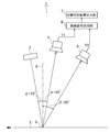
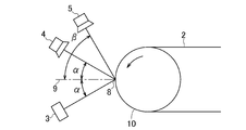
- the illumination unit 3 illuminates the imaging target portion 8 on the surface of the steel plate 2.
- the illumination unit 3 is disposed downstream of the surface 9 perpendicular to the traveling direction of the steel plate 2 (hereinafter also referred to as “orthogonal surface 9”) at the imaging target portion 8 in the traveling direction of the steel plate 2.
- a light source of the illumination unit 3 LED-type line illumination which illuminates the steel plate 2 in the plate width direction is used.
- the light source of the illumination unit 3 is not limited to this, and it is also possible to use a halogen, a metal halide, a fluorescent lamp or the like instead of the LED.
- the regular reflection light imaging unit 4 picks up the regular reflection light in which the light emitted from the illumination unit 3 is reflected by the imaging target portion 8 on the surface of the steel plate 2. Therefore, the specular reflection light imaging unit 4 is disposed on the upstream side of the orthogonal plane 9 in the traveling direction of the steel plate 2 and is disposed to receive specularly reflected light at the position of the angle ⁇ with respect to the orthogonal plane 9 .
- a CCD line sensor camera is used for the regular reflection light imaging unit 4. It is also possible to employ a CCD area sensor camera or the like instead of the CCD line sensor camera.
- the spatial resolution of the regular reflection light imaging unit 4 is appropriately determined according to the type of surface defect to be detected.
- the image signal processing unit 6 processes a regular reflection image signal T1 obtained by imaging by the regular reflection light imaging unit 4 and a diffuse reflection image signal T2 obtained by imaging by the diffuse reflection light imaging unit 5 to obtain a steel plate 2 surface defects are extracted, and the extracted surface defects are classified and determined.
- the image signal processing unit 6 is composed of various arithmetic processing units (for example, a personal computer in which a program necessary for executing the classification determination logic to be described later is incorporated). The determination result is transmitted to the upper process computer to perform quality determination.
- FIG. 1 a mode that surface defect inspection is performed with respect to the surface of the steel plate 2 which moves to a horizontal direction is shown in FIG. 1, as the surface defect inspection apparatus 1 is shown in FIG.
- the surface defect inspection can also be performed on the surface of the steel plate 2 moving along.
- the installation place of the surface inspection apparatus 1 is not particularly limited, it is preferable that the surface defect inspection by the surface inspection apparatus 1 be installed at a place where the final process of manufacturing the steel plate 2 is performed. . More specifically, it is desirable that the surface defect inspection by the surface inspection apparatus 1 is performed on the steel plate 2 before being wound on the tension reel after being subjected to the temper rolling process by the skin pass mill.
- the light receiving angle of the irregularly reflected light imaging unit 5 taking this into consideration It is desirable to set ⁇ .
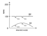
- the horizontal axis represents the reflection angle
- the vertical axis represents the brightness of the reflected light.
- the brightness at a regular reflection angle of 10 ° is the highest, and the brightness is attenuated as the reflection angle deviates from the regular reflection angle of 10 °.
- the degree of attenuation of this luminance is much greater in the case of formation than in the case of dross or non-plating.
- the brightness (curve G3) of the reflected light in the case where the reflection surface is a dross is higher than the above-mentioned reference on the basis of the brightness (curve G1) of the reflection light in the case where the reflection surface is ground.
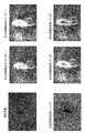
- each of the images shown in FIG. 4 relates to the non-dross plating in the dross appearing on the surface of the steel plate 2.
- In-dross non-plating is a surface defect that is unplated on the inside of dross.
- the real photograph is a photograph which photographed non-plating in dross.
- the brightness (curve G3) of the reflected light in the case where the reflection surface is a dross based on the brightness (curve G1) of the reflected light in the case where the reflection surface is a ground
- the diffusely reflected light imaging unit 5 is installed at a reflection angle position where the luminance of the reflected light (curve G2) when the luminance is high and the reflection surface is not plated is lower than the above reference, and the above reference (curve G1)
- the dross and the non-plating can be classified and determined if This is applicable not only to classification determination between dross and non-plating but also to classification determination of other types of surface defects.
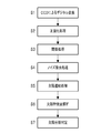
- the image signal processing unit 6 performs normalization processing on the regular reflection image signal T1 and the irregular reflection image signal T2 (S2), and then performs threshold processing (S3).
- the normalization process is caused by the difference in imaging position on the steel plate 2 due to the influence of the aberration of the lens included in each of the reflected light imaging units 4 and 5 and the difference in the illumination condition due to the difference in imaging position on the steel plate 2 This is performed to correct the variations and deviations of the values of the image signals T1 and T2.
- a standard normal distribution N (0) where the normal value N ( ⁇ , ⁇ 2 ) of the image signals T1 and T2 obtained in S1 is 0 in average value ⁇ and 1 in variance value ⁇ , respectively.
- the regular reflection image signal T1L whose luminance is lower than a predetermined threshold value P1 is regarded (extracted) as a defective portion.
- the threshold P1 may be a constant set in advance, but in the present embodiment, the threshold P1 is a value lower than the moving average value of the regular reflection image signals T1 in the imaging range of the regular reflection light imaging unit 4 by a predetermined value. There is.
- the irregular reflection image signal T2H having a luminance higher than the predetermined threshold P2 regarding the defective portion (a portion on the steel plate 2 where the specular reflection image signal T1 has an luminance lower than the predetermined threshold P1).
- the irregular reflection image signal T2L whose luminance is lower than a predetermined threshold value P2 is a second type defect (not plated or removed in the present embodiment). It is determined that
- the threshold P2 may be a constant set in advance, but in the present embodiment, a moving average value of the diffuse reflection image signal obtained by diffuse reflection from the ground and imaging by the diffuse light imaging unit 5 is taken as the threshold P2. .
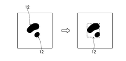
- the image signal processing unit 6 performs a noise removal process for extracting a pixel regarded as a defect site by the threshold process of the regular reflection image signal T1 (S4), and the pixels relating to the extracted defect site are selected.
- a defect linking process (S5) for linking In the noise removal processing, as shown in the left diagram of FIG. 8, among defects detected as the defective pixels 12 and 13 by the threshold processing, a defect having an isolated point (minute defect) that can be distinguished from the vicinity thereof.
- the pixel 13 is regarded as noise, and this is changed to a normal pixel as shown in the right diagram of FIG.
- a filter for changing the defective pixel 13 into a normal pixel
- an averaging filter for changing the defective pixel 13 into a normal pixel
- a low pass filter for changing the defective pixel 13 into a normal pixel
- a Gaussian filter for changing the defective pixel 13 into a normal pixel
- a Laplacian filter etc.
- the defect linking process for example, as shown in the left diagram of FIG. 9, when there are a plurality of defects 12 close to each other, as shown in the right diagram of FIG.
- One region (a region exemplified by a dotted line in FIG. 9 is a square region) is recognized as one defect 12.
- the image signal processing unit 6 determines the aspect ratio, roundness, and direction of the defect (the longitudinal direction of the defect with respect to the traveling direction of the steel plate 2 Analysis of feature quantities such as
- the density occupied by the pixels regarded as the defect site by the threshold process of the regular reflection image signal T1 the first type of defect site by the threshold process of the irregular reflection image signal T2.
- the density occupied by the pixels regarded as D, and the density occupied by the pixels regarded as the second kind of defect part by the threshold processing of the irregular reflection image signal T2 are respectively calculated (S6).
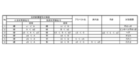
- the image signal processing unit 6 sets the aspect ratio, the roundness, and the like set in advance for each of the types of defects as shown in FIG. 6 with respect to the first type of defect site and the second type of defect site.
- the threshold condition for the density is applied, and the types of the first type of defect site (dross, dirt) and the second type of defect site (non-plating, pinhole non-plating, hesitation) are further classified and judged, If the defect site is a first-type defect site, classification is further finely classified as any of dross, dirt [1], dirt [2], and if the defect site is a second-type defect site, no plating, Classification is further finely classified as any of pinhole non-plating and thorn (S7).
- upper case letters “A”, “B”, “C” and “D” are actual values actually obtained in the surface defect inspection, and a combination of lower case letters and numbers “a1” and “b1” ,... are preset threshold values.
- this threshold value an optimal value obtained by repeating experiments on various surface defects is adopted. Note that “dark” in the "regular reflection image signal” column indicates that the luminance is lower than the above threshold P1, and “dark” in the "diffuse reflection image signal” column is that the luminance is lower than the above threshold P2. And “bright” in the “diffuse reflection image signal” column indicates that the luminance is higher than the threshold value P2 described above.
- the luminance information of the reflection image signal obtained from the regular reflection light and the irregular reflection light By combining and synchronizing, it is possible to classify and determine the type of surface defect extracted with high accuracy, without relying on the feature amount (aspect ratio, roundness of defect, orientation of defect, etc.) of the defect that is easily caused variation. Can. In the present embodiment, it is possible to classify and determine at least the first type defect and the second type defect with high accuracy without relying on the above-mentioned feature amount.
- the present invention can be applied to, for example, a surface defect inspection apparatus and a surface defect inspection method for hot-dip galvanized steel sheet.
- Hot-dip galvanized steel sheet hot-dip galvanized steel sheet
- Reference Signs List 3 illumination unit 4 regular reflection light imaging unit 5 irregular reflection light imaging unit 6 image signal processing unit 8 imaging target portion T1 regular reflection image signal T2 irregular reflection image signal
Landscapes
- Chemical & Material Sciences (AREA)
- Health & Medical Sciences (AREA)
- Life Sciences & Earth Sciences (AREA)
- Pathology (AREA)
- General Physics & Mathematics (AREA)
- Immunology (AREA)
- Physics & Mathematics (AREA)
- Analytical Chemistry (AREA)
- Biochemistry (AREA)
- General Health & Medical Sciences (AREA)
- Engineering & Computer Science (AREA)
- Food Science & Technology (AREA)
- Medicinal Chemistry (AREA)
- Textile Engineering (AREA)
- Crystallography & Structural Chemistry (AREA)
- Computer Vision & Pattern Recognition (AREA)
- Signal Processing (AREA)
- Investigating Materials By The Use Of Optical Means Adapted For Particular Applications (AREA)
Abstract
Description
2 溶融亜鉛めっき鋼板(溶融めっき鋼板)
3 照明部
4 正反射光撮像部
5 乱反射光撮像部
6 画像信号処理部
8 撮像対象部位
T1 正反射画像信号
T2 乱反射画像信号
Claims (4)
- 溶融めっき鋼板の表面上にある撮像対象部位を照明する照明部と、
前記撮像対象部位からの正反射光を撮像する正反射光撮像部と、
同撮像対象部位からの乱反射光を撮像する乱反射光撮像部と、
前記正反射光撮像部が撮像して得られた正反射画像信号と、前記乱反射光撮像部が撮像して得られた乱反射画像信号とを処理する画像信号処理部と、
を備える溶融めっき鋼板の表面欠陥検査装置において、
前記正反射光撮像部と前記乱反射光撮像部とは同時に前記撮像対象部位からの反射光を撮像するものであり、
前記画像信号処理部は、
前記正反射光撮像部が撮像して得られた正反射画像信号のうち、所定の閾値より低輝度の部位を表面欠陥部位として抽出し、
抽出された前記表面欠陥部位に対応する部位に関し、前記乱反射光撮像部が撮像して得られた乱反射画像信号に対し、閾値処理を行うことにより、抽出された前記表面欠陥部位の欠陥種類を分類判定する、
ことを特徴とする溶融めっき鋼板の表面欠陥検査装置。 - 請求項1に記載の溶融めっき鋼板の表面欠陥検査装置において、
前記画像信号処理部は、前記乱反射光撮像部が地合を撮像して得られる乱反射画像信号の移動平均値を算出し、算出された移動平均値を前記閾値処理の閾値として使用し、当該閾値より高輝度の部位と当該閾値より低輝度の部位とを互いに異なる種類の表面欠陥として分類判定する、
ことを特徴とする溶融めっき鋼板の表面欠陥検査装置。 - 溶融めっき鋼板の表面を照明し、
前記溶融めっき鋼板上の撮像対象部位からの正反射光および乱反射光をそれぞれ撮像し、
撮像してそれぞれ得られた正反射画像信号と乱反射画像信号とを処理する、
溶融めっき鋼板の表面欠陥検査方法において、
前記撮像対象部位からの正反射光の撮像と乱反射光の撮像は同時に行われるものであり、
前記処理は、
撮像して得られた正反射画像信号のうち、所定の閾値より低輝度の部位を表面欠陥部位として抽出し、
抽出された前記表面欠陥部位に対応する部位に関し、撮像して得られた乱反射画像信号に対し、閾値処理を行うことにより、抽出された前記表面欠陥部位の欠陥種類を分類判定するものである、
ことを特徴とする溶融めっき鋼板の表面欠陥検査方法。 - 請求項3に記載の溶融めっき鋼板の表面欠陥検査方法において、
前記処理において、地合を撮像して得られる乱反射画像信号の移動平均値を算出し、算出された移動平均値を前記閾値処理の閾値として使用し、当該閾値より高輝度の部位と当該閾値より低輝度の部位とを互いに異なる種類の表面欠陥として分類判定する、
ことを特徴とする溶融めっき鋼板の表面欠陥検査方法。
Priority Applications (7)
| Application Number | Priority Date | Filing Date | Title |
|---|---|---|---|
| KR1020177027720A KR101800597B1 (ko) | 2015-03-31 | 2016-03-28 | 용융 도금 강판의 표면 결함 검사 장치 및 표면 결함 검사 방법 |
| EP16772754.4A EP3279645A4 (en) | 2015-03-31 | 2016-03-28 | Device for examining surface defect in hot-dipped steel plate, and method for examining surface defect |
| MX2017012698A MX360696B (es) | 2015-03-31 | 2016-03-28 | Dispositivo y método de inspección de defectos superficiales para chapas de acero revestidas por inmersión en caliente. |
| CN201680008920.5A CN107533012B (zh) | 2015-03-31 | 2016-03-28 | 熔融镀覆钢板的表面缺陷检查装置及表面缺陷检查方法 |
| JP2016526949A JP6027295B1 (ja) | 2015-03-31 | 2016-03-28 | 溶融めっき鋼板の表面欠陥検査装置および表面欠陥検査方法 |
| BR112017021163-7A BR112017021163A2 (ja) | 2015-03-31 | 2016-03-28 | A surface defect inspection device and a surface defect inspection method of a hot-dipping steel plate |
| US15/717,703 US10041888B2 (en) | 2015-03-31 | 2017-09-27 | Surface defect inspecting device and method for hot-dip coated steel sheets |
Applications Claiming Priority (2)
| Application Number | Priority Date | Filing Date | Title |
|---|---|---|---|
| JP2015-070692 | 2015-03-31 | ||
| JP2015070692 | 2015-03-31 |
Related Child Applications (1)
| Application Number | Title | Priority Date | Filing Date |
|---|---|---|---|
| US15/717,703 Continuation US10041888B2 (en) | 2015-03-31 | 2017-09-27 | Surface defect inspecting device and method for hot-dip coated steel sheets |
Publications (1)
| Publication Number | Publication Date |
|---|---|
| WO2016158873A1 true WO2016158873A1 (ja) | 2016-10-06 |
Family
ID=57005108
Family Applications (1)
| Application Number | Title | Priority Date | Filing Date |
|---|---|---|---|
| PCT/JP2016/059963 Ceased WO2016158873A1 (ja) | 2015-03-31 | 2016-03-28 | 溶融めっき鋼板の表面欠陥検査装置および表面欠陥検査方法 |
Country Status (10)
| Country | Link |
|---|---|
| US (1) | US10041888B2 (ja) |
| EP (1) | EP3279645A4 (ja) |
| JP (1) | JP6027295B1 (ja) |
| KR (1) | KR101800597B1 (ja) |
| CN (1) | CN107533012B (ja) |
| BR (1) | BR112017021163A2 (ja) |
| MX (1) | MX360696B (ja) |
| MY (1) | MY165130A (ja) |
| TW (1) | TWI627399B (ja) |
| WO (1) | WO2016158873A1 (ja) |
Cited By (3)
| Publication number | Priority date | Publication date | Assignee | Title |
|---|---|---|---|---|
| US10041888B2 (en) | 2015-03-31 | 2018-08-07 | Nisshin Steel Co., Ltd. | Surface defect inspecting device and method for hot-dip coated steel sheets |
| CN109557084A (zh) * | 2019-01-17 | 2019-04-02 | 南通市产品质量监督检验所 | 以镀层铁元素含量鉴定制绳镀锌钢丝镀锌方式的检测方法 |
| JP7495163B1 (ja) | 2023-03-08 | 2024-06-04 | 株式会社ヒューテック | 欠点撮像装置およびそこで用いられる詳細撮像装置 |
Families Citing this family (14)
| Publication number | Priority date | Publication date | Assignee | Title |
|---|---|---|---|---|
| JP6117398B1 (ja) | 2016-03-30 | 2017-04-19 | 日新製鋼株式会社 | 鋼板の表面欠陥検査装置および表面欠陥検査方法 |
| TWI630366B (zh) * | 2017-04-28 | 2018-07-21 | 中國鋼鐵股份有限公司 | 鋼板寬度量測系統及其方法 |
| JP7209157B2 (ja) * | 2018-10-01 | 2023-01-20 | 富山住友電工株式会社 | めっき線材の製造方法およびめっき線材の製造装置 |
| WO2020183958A1 (ja) * | 2019-03-08 | 2020-09-17 | Jfeスチール株式会社 | 化成処理膜検査方法、化成処理膜検査装置、表面処理鋼板の製造方法、表面処理鋼板の品質管理方法及び表面処理鋼板の製造設備 |
| DE102019204346A1 (de) * | 2019-03-28 | 2020-10-01 | Volkswagen Aktiengesellschaft | Verfahren und System zum Überprüfen einer optischen Beanstandung an einem Kraftfahrzeug |
| JP7252488B2 (ja) * | 2019-03-29 | 2023-04-05 | ダイキン工業株式会社 | 成形品の検査方法、及び、成形品の製造方法 |
| DE102019210727A1 (de) * | 2019-07-19 | 2021-01-21 | Thyssenkrupp Steel Europe Ag | Verfahren zum Bestimmen eines Reinigungszustands einer Oberfläche eines Flachprodukts und Flachprodukt |
| CN110738237A (zh) * | 2019-09-16 | 2020-01-31 | 深圳新视智科技术有限公司 | 缺陷分类的方法、装置、计算机设备和存储介质 |
| EP4194842A4 (en) * | 2020-08-06 | 2024-01-17 | JFE Steel Corporation | Metal strip surface inspection device, surface inspection method, and manufacturing method |
| KR102818192B1 (ko) * | 2020-10-27 | 2025-06-10 | 제이에프이 스틸 가부시키가이샤 | 표면 온도 계측 방법, 표면 온도 계측 장치, 아연계 용융 도금 강판의 제조 방법 및, 아연계 용융 도금 강판의 제조 설비 |
| CN112345555A (zh) * | 2020-10-30 | 2021-02-09 | 凌云光技术股份有限公司 | 外观检查机高亮成像光源系统 |
| EP4260958B1 (en) * | 2021-07-01 | 2025-06-18 | Primetals Technologies Japan, Ltd. | Abnormality detection device and abnormality detection method |
| TWI860746B (zh) * | 2022-06-10 | 2024-11-01 | 日商日本製鐵股份有限公司 | 熔融鍍敷鋼板之觀察裝置及熔融鍍敷鋼板之觀察方法 |
| CN120609830B (zh) * | 2025-07-09 | 2025-12-23 | 山东美饰佳装饰材料有限公司 | 一种浸渍纸表面缺陷检测系统及方法 |
Citations (6)
| Publication number | Priority date | Publication date | Assignee | Title |
|---|---|---|---|---|
| JPH04315952A (ja) * | 1991-04-15 | 1992-11-06 | Nkk Corp | 表面処理鋼板の品質検査方法及びその装置 |
| JPH0882604A (ja) * | 1994-09-12 | 1996-03-26 | Nippon Steel Corp | 鋼板表面欠陥検査方法 |
| JPH11183396A (ja) * | 1997-12-25 | 1999-07-09 | Nkk Corp | 表面疵検査装置及びその方法 |
| JPH11183397A (ja) * | 1997-12-25 | 1999-07-09 | Nkk Corp | 表面疵検査装置及びその方法 |
| JP2010249685A (ja) * | 2009-04-16 | 2010-11-04 | Nippon Steel Corp | 疵検出装置、疵検出方法及びプログラム |
| JP2012103017A (ja) * | 2010-11-05 | 2012-05-31 | Jfe Steel Corp | 溶融金属メッキ鋼板のドロス欠陥検査装置およびドロス欠陥検査方法 |
Family Cites Families (18)
| Publication number | Priority date | Publication date | Assignee | Title |
|---|---|---|---|---|
| GB1057802A (en) * | 1962-08-13 | 1967-02-08 | Yawata Iron & Steel Company | Ultrasonic internal flaw detecting apparatus for hot metal |
| CA1229392A (en) * | 1984-02-28 | 1987-11-17 | Hirosato Yamane | Method and apparatus for detection of surface defects of hot metal body |
| US5087822A (en) * | 1990-06-22 | 1992-02-11 | Alcan International Limited | Illumination system with incident beams from near and far dark field for high speed surface inspection of rolled aluminum sheet |
| EP0543648A1 (en) * | 1991-11-21 | 1993-05-26 | Kaisei Engineer Co., Ltd. | Inspection device using electromagnetic induction and method therefor |
| AU6014594A (en) * | 1993-02-02 | 1994-08-29 | Golden Aluminum Company | Method and apparatus for imaging surfaces |
| JPH08278258A (ja) * | 1995-04-10 | 1996-10-22 | Nippon Steel Corp | 表面検査装置 |
| CA2365879C (en) * | 1999-03-18 | 2009-11-24 | Nkk Corporation | Method for marking defect and device therefor |
| US6923067B2 (en) * | 1999-03-19 | 2005-08-02 | Betriebsforschungsinstitut Vdeh Institut Fur Angewandte Forschung Gmbh | Defect type classifying method |
| WO2002040970A1 (en) * | 2000-11-15 | 2002-05-23 | Real Time Metrology, Inc. | Optical method and apparatus for inspecting large area planar objects |
| JP4136938B2 (ja) * | 2001-12-13 | 2008-08-20 | 国際技術開発株式会社 | 銅箔検査装置、銅箔検査方法 |
| JP2003344300A (ja) * | 2002-05-21 | 2003-12-03 | Jfe Steel Kk | 表面欠陥判別方法 |
| JP2004151006A (ja) * | 2002-10-31 | 2004-05-27 | Jfe Steel Kk | 溶融亜鉛めっき鋼板の品質管理方法及び溶融亜鉛めっき鋼板の品質管理装置 |
| JP2006177746A (ja) * | 2004-12-22 | 2006-07-06 | Jfe Steel Kk | 表面欠陥検出方法および装置 |
| EP2554977B1 (en) * | 2010-03-30 | 2020-10-14 | JFE Steel Corporation | Surface detection method for steel plate having resin coating film and surface detection device for same |
| JP5820735B2 (ja) * | 2012-01-27 | 2015-11-24 | 昭和電工株式会社 | 表面検査方法及び表面検査装置 |
| JP6104745B2 (ja) * | 2013-07-23 | 2017-03-29 | 株式会社東芝 | 穴検査装置 |
| CN103743709A (zh) * | 2014-01-15 | 2014-04-23 | 唐山英莱科技有限公司 | 一种基于多层介质反射镜成像的线结构光焊缝检测系统 |
| EP3279645A4 (en) | 2015-03-31 | 2018-09-26 | Nisshin Steel Co., Ltd. | Device for examining surface defect in hot-dipped steel plate, and method for examining surface defect |
-
2016
- 2016-03-28 EP EP16772754.4A patent/EP3279645A4/en not_active Withdrawn
- 2016-03-28 WO PCT/JP2016/059963 patent/WO2016158873A1/ja not_active Ceased
- 2016-03-28 BR BR112017021163-7A patent/BR112017021163A2/ja not_active Application Discontinuation
- 2016-03-28 CN CN201680008920.5A patent/CN107533012B/zh not_active Expired - Fee Related
- 2016-03-28 KR KR1020177027720A patent/KR101800597B1/ko not_active Expired - Fee Related
- 2016-03-28 MY MYPI2017703620A patent/MY165130A/en unknown
- 2016-03-28 MX MX2017012698A patent/MX360696B/es active IP Right Grant
- 2016-03-28 JP JP2016526949A patent/JP6027295B1/ja active Active
- 2016-03-30 TW TW105110026A patent/TWI627399B/zh not_active IP Right Cessation
-
2017
- 2017-09-27 US US15/717,703 patent/US10041888B2/en not_active Expired - Fee Related
Patent Citations (6)
| Publication number | Priority date | Publication date | Assignee | Title |
|---|---|---|---|---|
| JPH04315952A (ja) * | 1991-04-15 | 1992-11-06 | Nkk Corp | 表面処理鋼板の品質検査方法及びその装置 |
| JPH0882604A (ja) * | 1994-09-12 | 1996-03-26 | Nippon Steel Corp | 鋼板表面欠陥検査方法 |
| JPH11183396A (ja) * | 1997-12-25 | 1999-07-09 | Nkk Corp | 表面疵検査装置及びその方法 |
| JPH11183397A (ja) * | 1997-12-25 | 1999-07-09 | Nkk Corp | 表面疵検査装置及びその方法 |
| JP2010249685A (ja) * | 2009-04-16 | 2010-11-04 | Nippon Steel Corp | 疵検出装置、疵検出方法及びプログラム |
| JP2012103017A (ja) * | 2010-11-05 | 2012-05-31 | Jfe Steel Corp | 溶融金属メッキ鋼板のドロス欠陥検査装置およびドロス欠陥検査方法 |
Non-Patent Citations (1)
| Title |
|---|
| See also references of EP3279645A4 * |
Cited By (4)
| Publication number | Priority date | Publication date | Assignee | Title |
|---|---|---|---|---|
| US10041888B2 (en) | 2015-03-31 | 2018-08-07 | Nisshin Steel Co., Ltd. | Surface defect inspecting device and method for hot-dip coated steel sheets |
| CN109557084A (zh) * | 2019-01-17 | 2019-04-02 | 南通市产品质量监督检验所 | 以镀层铁元素含量鉴定制绳镀锌钢丝镀锌方式的检测方法 |
| JP7495163B1 (ja) | 2023-03-08 | 2024-06-04 | 株式会社ヒューテック | 欠点撮像装置およびそこで用いられる詳細撮像装置 |
| JP2024126629A (ja) * | 2023-03-08 | 2024-09-20 | 株式会社ヒューテック | 欠点撮像装置およびそこで用いられる詳細撮像装置 |
Also Published As
| Publication number | Publication date |
|---|---|
| CN107533012A (zh) | 2018-01-02 |
| TW201640101A (zh) | 2016-11-16 |
| US10041888B2 (en) | 2018-08-07 |
| EP3279645A4 (en) | 2018-09-26 |
| TWI627399B (zh) | 2018-06-21 |
| KR20170117600A (ko) | 2017-10-23 |
| BR112017021163A2 (ja) | 2018-07-17 |
| KR101800597B1 (ko) | 2017-11-22 |
| JP6027295B1 (ja) | 2016-11-16 |
| MX360696B (es) | 2018-11-14 |
| MY165130A (en) | 2018-02-28 |
| CN107533012B (zh) | 2019-07-19 |
| US20180017503A1 (en) | 2018-01-18 |
| EP3279645A1 (en) | 2018-02-07 |
| MX2017012698A (es) | 2018-01-11 |
| JPWO2016158873A1 (ja) | 2017-04-27 |
Similar Documents
| Publication | Publication Date | Title |
|---|---|---|
| JP6027295B1 (ja) | 溶融めっき鋼板の表面欠陥検査装置および表面欠陥検査方法 | |
| JP6117398B1 (ja) | 鋼板の表面欠陥検査装置および表面欠陥検査方法 | |
| US12320756B2 (en) | Surface-defect detecting method, surface-defect detecting apparatus, steel-material manufacturing method, steel-material quality management method, steel-material manufacturing facility, surface-defect determination model generating method, and surface-defect determination model | |
| KR101343277B1 (ko) | 표면 검사 장치 | |
| JP5594071B2 (ja) | 溶融金属メッキ鋼板のドロス欠陥検査装置およびドロス欠陥検査方法 | |
| JP2012251983A (ja) | ラップフィルム皺検査方法及び装置 | |
| CN113820319A (zh) | 一种纺织品表面缺陷检测装置与方法 | |
| KR20230017312A (ko) | 금속띠의 표면 검사 장치, 표면 검사 방법, 및 제조 방법 | |
| CN110402386A (zh) | 圆筒体表面检查装置及圆筒体表面检查方法 | |
| JP6950811B2 (ja) | 金属板の表面欠陥検出方法及び装置並びにめっき鋼板の製造方法 | |
| JP2010085166A (ja) | プリプレグ欠点検査方法 | |
| US20070115462A1 (en) | Method for inspecting the quality criteria of flat textile structures embodied in a multi-layer form according to a contour | |
| JP4739044B2 (ja) | 外観検査装置 | |
| JP5949690B2 (ja) | 評価方法及び評価装置 | |
| JP4403036B2 (ja) | 疵検出方法及び装置 | |
| JP2004125629A (ja) | 欠陥検出装置 | |
| JP2014186030A (ja) | 欠点検査装置 | |
| JPH08219740A (ja) | 半導体装置の検査方法及び装置 | |
| JP2025144515A (ja) | 合金化溶融亜鉛めっき鋼板の欠陥検査装置および合金化溶融亜鉛めっき鋼板の欠陥検査方法 | |
| JPH09145639A (ja) | 表面検査装置 |
Legal Events
| Date | Code | Title | Description |
|---|---|---|---|
| ENP | Entry into the national phase |
Ref document number: 2016526949 Country of ref document: JP Kind code of ref document: A |
|
| 121 | Ep: the epo has been informed by wipo that ep was designated in this application |
Ref document number: 16772754 Country of ref document: EP Kind code of ref document: A1 |
|
| ENP | Entry into the national phase |
Ref document number: 20177027720 Country of ref document: KR Kind code of ref document: A |
|
| WWE | Wipo information: entry into national phase |
Ref document number: MX/A/2017/012698 Country of ref document: MX |
|
| NENP | Non-entry into the national phase |
Ref country code: DE |
|
| REEP | Request for entry into the european phase |
Ref document number: 2016772754 Country of ref document: EP |
|
| REG | Reference to national code |
Ref country code: BR Ref legal event code: B01A Ref document number: 112017021163 Country of ref document: BR |
|
| ENP | Entry into the national phase |
Ref document number: 112017021163 Country of ref document: BR Kind code of ref document: A2 Effective date: 20171002 |