WO2016159010A1 - 金属、樹脂部材及び炭素繊維強化樹脂部材の接合方法 - Google Patents
金属、樹脂部材及び炭素繊維強化樹脂部材の接合方法 Download PDFInfo
- Publication number
- WO2016159010A1 WO2016159010A1 PCT/JP2016/060246 JP2016060246W WO2016159010A1 WO 2016159010 A1 WO2016159010 A1 WO 2016159010A1 JP 2016060246 W JP2016060246 W JP 2016060246W WO 2016159010 A1 WO2016159010 A1 WO 2016159010A1
- Authority
- WO
- WIPO (PCT)
- Prior art keywords
- metal
- joining
- resin
- resin member
- laser
- Prior art date
- Legal status (The legal status is an assumption and is not a legal conclusion. Google has not performed a legal analysis and makes no representation as to the accuracy of the status listed.)
- Ceased
Links
Images







Classifications
-
- B—PERFORMING OPERATIONS; TRANSPORTING
- B29—WORKING OF PLASTICS; WORKING OF SUBSTANCES IN A PLASTIC STATE IN GENERAL
- B29C—SHAPING OR JOINING OF PLASTICS; SHAPING OF MATERIAL IN A PLASTIC STATE, NOT OTHERWISE PROVIDED FOR; AFTER-TREATMENT OF THE SHAPED PRODUCTS, e.g. REPAIRING
- B29C65/00—Joining or sealing of preformed parts, e.g. welding of plastics materials; Apparatus therefor
- B29C65/02—Joining or sealing of preformed parts, e.g. welding of plastics materials; Apparatus therefor by heating, with or without pressure
- B29C65/14—Joining or sealing of preformed parts, e.g. welding of plastics materials; Apparatus therefor by heating, with or without pressure using wave energy, i.e. electromagnetic radiation, or particle radiation
- B29C65/16—Laser beams
- B29C65/1629—Laser beams characterised by the way of heating the interface
-
- B—PERFORMING OPERATIONS; TRANSPORTING
- B29—WORKING OF PLASTICS; WORKING OF SUBSTANCES IN A PLASTIC STATE IN GENERAL
- B29C—SHAPING OR JOINING OF PLASTICS; SHAPING OF MATERIAL IN A PLASTIC STATE, NOT OTHERWISE PROVIDED FOR; AFTER-TREATMENT OF THE SHAPED PRODUCTS, e.g. REPAIRING
- B29C65/00—Joining or sealing of preformed parts, e.g. welding of plastics materials; Apparatus therefor
- B29C65/02—Joining or sealing of preformed parts, e.g. welding of plastics materials; Apparatus therefor by heating, with or without pressure
- B29C65/14—Joining or sealing of preformed parts, e.g. welding of plastics materials; Apparatus therefor by heating, with or without pressure using wave energy, i.e. electromagnetic radiation, or particle radiation
- B29C65/16—Laser beams
-
- B—PERFORMING OPERATIONS; TRANSPORTING
- B29—WORKING OF PLASTICS; WORKING OF SUBSTANCES IN A PLASTIC STATE IN GENERAL
- B29C—SHAPING OR JOINING OF PLASTICS; SHAPING OF MATERIAL IN A PLASTIC STATE, NOT OTHERWISE PROVIDED FOR; AFTER-TREATMENT OF THE SHAPED PRODUCTS, e.g. REPAIRING
- B29C65/00—Joining or sealing of preformed parts, e.g. welding of plastics materials; Apparatus therefor
- B29C65/02—Joining or sealing of preformed parts, e.g. welding of plastics materials; Apparatus therefor by heating, with or without pressure
- B29C65/14—Joining or sealing of preformed parts, e.g. welding of plastics materials; Apparatus therefor by heating, with or without pressure using wave energy, i.e. electromagnetic radiation, or particle radiation
- B29C65/16—Laser beams
- B29C65/1603—Laser beams characterised by the type of electromagnetic radiation
- B29C65/1612—Infrared [IR] radiation, e.g. by infrared lasers
- B29C65/1616—Near infrared radiation [NIR], e.g. by YAG lasers
-
- B—PERFORMING OPERATIONS; TRANSPORTING
- B29—WORKING OF PLASTICS; WORKING OF SUBSTANCES IN A PLASTIC STATE IN GENERAL
- B29C—SHAPING OR JOINING OF PLASTICS; SHAPING OF MATERIAL IN A PLASTIC STATE, NOT OTHERWISE PROVIDED FOR; AFTER-TREATMENT OF THE SHAPED PRODUCTS, e.g. REPAIRING
- B29C65/00—Joining or sealing of preformed parts, e.g. welding of plastics materials; Apparatus therefor
- B29C65/02—Joining or sealing of preformed parts, e.g. welding of plastics materials; Apparatus therefor by heating, with or without pressure
- B29C65/14—Joining or sealing of preformed parts, e.g. welding of plastics materials; Apparatus therefor by heating, with or without pressure using wave energy, i.e. electromagnetic radiation, or particle radiation
- B29C65/16—Laser beams
- B29C65/1629—Laser beams characterised by the way of heating the interface
- B29C65/1635—Laser beams characterised by the way of heating the interface at least passing through one of the parts to be joined, i.e. laser transmission welding
-
- B—PERFORMING OPERATIONS; TRANSPORTING
- B29—WORKING OF PLASTICS; WORKING OF SUBSTANCES IN A PLASTIC STATE IN GENERAL
- B29C—SHAPING OR JOINING OF PLASTICS; SHAPING OF MATERIAL IN A PLASTIC STATE, NOT OTHERWISE PROVIDED FOR; AFTER-TREATMENT OF THE SHAPED PRODUCTS, e.g. REPAIRING
- B29C65/00—Joining or sealing of preformed parts, e.g. welding of plastics materials; Apparatus therefor
- B29C65/02—Joining or sealing of preformed parts, e.g. welding of plastics materials; Apparatus therefor by heating, with or without pressure
- B29C65/14—Joining or sealing of preformed parts, e.g. welding of plastics materials; Apparatus therefor by heating, with or without pressure using wave energy, i.e. electromagnetic radiation, or particle radiation
- B29C65/16—Laser beams
- B29C65/1629—Laser beams characterised by the way of heating the interface
- B29C65/1654—Laser beams characterised by the way of heating the interface scanning at least one of the parts to be joined
- B29C65/1658—Laser beams characterised by the way of heating the interface scanning at least one of the parts to be joined scanning once, e.g. contour laser welding
-
- B—PERFORMING OPERATIONS; TRANSPORTING
- B29—WORKING OF PLASTICS; WORKING OF SUBSTANCES IN A PLASTIC STATE IN GENERAL
- B29C—SHAPING OR JOINING OF PLASTICS; SHAPING OF MATERIAL IN A PLASTIC STATE, NOT OTHERWISE PROVIDED FOR; AFTER-TREATMENT OF THE SHAPED PRODUCTS, e.g. REPAIRING
- B29C65/00—Joining or sealing of preformed parts, e.g. welding of plastics materials; Apparatus therefor
- B29C65/02—Joining or sealing of preformed parts, e.g. welding of plastics materials; Apparatus therefor by heating, with or without pressure
- B29C65/44—Joining a heated non plastics element to a plastics element
-
- B—PERFORMING OPERATIONS; TRANSPORTING
- B29—WORKING OF PLASTICS; WORKING OF SUBSTANCES IN A PLASTIC STATE IN GENERAL
- B29C—SHAPING OR JOINING OF PLASTICS; SHAPING OF MATERIAL IN A PLASTIC STATE, NOT OTHERWISE PROVIDED FOR; AFTER-TREATMENT OF THE SHAPED PRODUCTS, e.g. REPAIRING
- B29C65/00—Joining or sealing of preformed parts, e.g. welding of plastics materials; Apparatus therefor
- B29C65/48—Joining or sealing of preformed parts, e.g. welding of plastics materials; Apparatus therefor using adhesives, i.e. using supplementary joining material; solvent bonding
- B29C65/50—Joining or sealing of preformed parts, e.g. welding of plastics materials; Apparatus therefor using adhesives, i.e. using supplementary joining material; solvent bonding using adhesive tape, e.g. thermoplastic tape; using threads or the like
- B29C65/5057—Joining or sealing of preformed parts, e.g. welding of plastics materials; Apparatus therefor using adhesives, i.e. using supplementary joining material; solvent bonding using adhesive tape, e.g. thermoplastic tape; using threads or the like positioned between the surfaces to be joined
-
- B—PERFORMING OPERATIONS; TRANSPORTING
- B29—WORKING OF PLASTICS; WORKING OF SUBSTANCES IN A PLASTIC STATE IN GENERAL
- B29C—SHAPING OR JOINING OF PLASTICS; SHAPING OF MATERIAL IN A PLASTIC STATE, NOT OTHERWISE PROVIDED FOR; AFTER-TREATMENT OF THE SHAPED PRODUCTS, e.g. REPAIRING
- B29C65/00—Joining or sealing of preformed parts, e.g. welding of plastics materials; Apparatus therefor
- B29C65/78—Means for handling the parts to be joined, e.g. for making containers or hollow articles, e.g. means for handling sheets, plates, web-like materials, tubular articles, hollow articles or elements to be joined therewith; Means for discharging the joined articles from the joining apparatus
- B29C65/7841—Holding or clamping means for handling purposes
-
- B—PERFORMING OPERATIONS; TRANSPORTING
- B29—WORKING OF PLASTICS; WORKING OF SUBSTANCES IN A PLASTIC STATE IN GENERAL
- B29C—SHAPING OR JOINING OF PLASTICS; SHAPING OF MATERIAL IN A PLASTIC STATE, NOT OTHERWISE PROVIDED FOR; AFTER-TREATMENT OF THE SHAPED PRODUCTS, e.g. REPAIRING
- B29C65/00—Joining or sealing of preformed parts, e.g. welding of plastics materials; Apparatus therefor
- B29C65/82—Testing the joint
- B29C65/8207—Testing the joint by mechanical methods
- B29C65/8215—Tensile tests
-
- B—PERFORMING OPERATIONS; TRANSPORTING
- B29—WORKING OF PLASTICS; WORKING OF SUBSTANCES IN A PLASTIC STATE IN GENERAL
- B29C—SHAPING OR JOINING OF PLASTICS; SHAPING OF MATERIAL IN A PLASTIC STATE, NOT OTHERWISE PROVIDED FOR; AFTER-TREATMENT OF THE SHAPED PRODUCTS, e.g. REPAIRING
- B29C66/00—General aspects of processes or apparatus for joining preformed parts
- B29C66/01—General aspects dealing with the joint area or with the area to be joined
- B29C66/05—Particular design of joint configurations
- B29C66/10—Particular design of joint configurations particular design of the joint cross-sections
- B29C66/11—Joint cross-sections comprising a single joint-segment, i.e. one of the parts to be joined comprising a single joint-segment in the joint cross-section
- B29C66/112—Single lapped joints
- B29C66/1122—Single lap to lap joints, i.e. overlap joints
-
- B—PERFORMING OPERATIONS; TRANSPORTING
- B29—WORKING OF PLASTICS; WORKING OF SUBSTANCES IN A PLASTIC STATE IN GENERAL
- B29C—SHAPING OR JOINING OF PLASTICS; SHAPING OF MATERIAL IN A PLASTIC STATE, NOT OTHERWISE PROVIDED FOR; AFTER-TREATMENT OF THE SHAPED PRODUCTS, e.g. REPAIRING
- B29C66/00—General aspects of processes or apparatus for joining preformed parts
- B29C66/40—General aspects of joining substantially flat articles, e.g. plates, sheets or web-like materials; Making flat seams in tubular or hollow articles; Joining single elements to substantially flat surfaces
- B29C66/41—Joining substantially flat articles ; Making flat seams in tubular or hollow articles
- B29C66/43—Joining a relatively small portion of the surface of said articles
-
- B—PERFORMING OPERATIONS; TRANSPORTING
- B29—WORKING OF PLASTICS; WORKING OF SUBSTANCES IN A PLASTIC STATE IN GENERAL
- B29C—SHAPING OR JOINING OF PLASTICS; SHAPING OF MATERIAL IN A PLASTIC STATE, NOT OTHERWISE PROVIDED FOR; AFTER-TREATMENT OF THE SHAPED PRODUCTS, e.g. REPAIRING
- B29C66/00—General aspects of processes or apparatus for joining preformed parts
- B29C66/70—General aspects of processes or apparatus for joining preformed parts characterised by the composition, physical properties or the structure of the material of the parts to be joined; Joining with non-plastics material
- B29C66/71—General aspects of processes or apparatus for joining preformed parts characterised by the composition, physical properties or the structure of the material of the parts to be joined; Joining with non-plastics material characterised by the composition of the plastics material of the parts to be joined
-
- B—PERFORMING OPERATIONS; TRANSPORTING
- B29—WORKING OF PLASTICS; WORKING OF SUBSTANCES IN A PLASTIC STATE IN GENERAL
- B29C—SHAPING OR JOINING OF PLASTICS; SHAPING OF MATERIAL IN A PLASTIC STATE, NOT OTHERWISE PROVIDED FOR; AFTER-TREATMENT OF THE SHAPED PRODUCTS, e.g. REPAIRING
- B29C66/00—General aspects of processes or apparatus for joining preformed parts
- B29C66/70—General aspects of processes or apparatus for joining preformed parts characterised by the composition, physical properties or the structure of the material of the parts to be joined; Joining with non-plastics material
- B29C66/72—General aspects of processes or apparatus for joining preformed parts characterised by the composition, physical properties or the structure of the material of the parts to be joined; Joining with non-plastics material characterised by the structure of the material of the parts to be joined
- B29C66/721—Fibre-reinforced materials
- B29C66/7212—Fibre-reinforced materials characterised by the composition of the fibres
-
- B—PERFORMING OPERATIONS; TRANSPORTING
- B29—WORKING OF PLASTICS; WORKING OF SUBSTANCES IN A PLASTIC STATE IN GENERAL
- B29C—SHAPING OR JOINING OF PLASTICS; SHAPING OF MATERIAL IN A PLASTIC STATE, NOT OTHERWISE PROVIDED FOR; AFTER-TREATMENT OF THE SHAPED PRODUCTS, e.g. REPAIRING
- B29C66/00—General aspects of processes or apparatus for joining preformed parts
- B29C66/70—General aspects of processes or apparatus for joining preformed parts characterised by the composition, physical properties or the structure of the material of the parts to be joined; Joining with non-plastics material
- B29C66/74—Joining plastics material to non-plastics material
- B29C66/742—Joining plastics material to non-plastics material to metals or their alloys
-
- B—PERFORMING OPERATIONS; TRANSPORTING
- B29—WORKING OF PLASTICS; WORKING OF SUBSTANCES IN A PLASTIC STATE IN GENERAL
- B29C—SHAPING OR JOINING OF PLASTICS; SHAPING OF MATERIAL IN A PLASTIC STATE, NOT OTHERWISE PROVIDED FOR; AFTER-TREATMENT OF THE SHAPED PRODUCTS, e.g. REPAIRING
- B29C66/00—General aspects of processes or apparatus for joining preformed parts
- B29C66/70—General aspects of processes or apparatus for joining preformed parts characterised by the composition, physical properties or the structure of the material of the parts to be joined; Joining with non-plastics material
- B29C66/74—Joining plastics material to non-plastics material
- B29C66/742—Joining plastics material to non-plastics material to metals or their alloys
- B29C66/7428—Transition metals or their alloys
- B29C66/74283—Iron or alloys of iron, e.g. steel
-
- B—PERFORMING OPERATIONS; TRANSPORTING
- B29—WORKING OF PLASTICS; WORKING OF SUBSTANCES IN A PLASTIC STATE IN GENERAL
- B29C—SHAPING OR JOINING OF PLASTICS; SHAPING OF MATERIAL IN A PLASTIC STATE, NOT OTHERWISE PROVIDED FOR; AFTER-TREATMENT OF THE SHAPED PRODUCTS, e.g. REPAIRING
- B29C66/00—General aspects of processes or apparatus for joining preformed parts
- B29C66/70—General aspects of processes or apparatus for joining preformed parts characterised by the composition, physical properties or the structure of the material of the parts to be joined; Joining with non-plastics material
- B29C66/74—Joining plastics material to non-plastics material
- B29C66/746—Joining plastics material to non-plastics material to inorganic materials not provided for in groups B29C66/742 - B29C66/744
- B29C66/7465—Glass
-
- B—PERFORMING OPERATIONS; TRANSPORTING
- B29—WORKING OF PLASTICS; WORKING OF SUBSTANCES IN A PLASTIC STATE IN GENERAL
- B29C—SHAPING OR JOINING OF PLASTICS; SHAPING OF MATERIAL IN A PLASTIC STATE, NOT OTHERWISE PROVIDED FOR; AFTER-TREATMENT OF THE SHAPED PRODUCTS, e.g. REPAIRING
- B29C66/00—General aspects of processes or apparatus for joining preformed parts
- B29C66/80—General aspects of machine operations or constructions and parts thereof
- B29C66/81—General aspects of the pressing elements, i.e. the elements applying pressure on the parts to be joined in the area to be joined, e.g. the welding jaws or clamps
- B29C66/812—General aspects of the pressing elements, i.e. the elements applying pressure on the parts to be joined in the area to be joined, e.g. the welding jaws or clamps characterised by the composition, by the structure, by the intensive physical properties or by the optical properties of the material constituting the pressing elements, e.g. constituting the welding jaws or clamps
- B29C66/8122—General aspects of the pressing elements, i.e. the elements applying pressure on the parts to be joined in the area to be joined, e.g. the welding jaws or clamps characterised by the composition, by the structure, by the intensive physical properties or by the optical properties of the material constituting the pressing elements, e.g. constituting the welding jaws or clamps characterised by the composition of the material constituting the pressing elements, e.g. constituting the welding jaws or clamps
-
- B—PERFORMING OPERATIONS; TRANSPORTING
- B29—WORKING OF PLASTICS; WORKING OF SUBSTANCES IN A PLASTIC STATE IN GENERAL
- B29C—SHAPING OR JOINING OF PLASTICS; SHAPING OF MATERIAL IN A PLASTIC STATE, NOT OTHERWISE PROVIDED FOR; AFTER-TREATMENT OF THE SHAPED PRODUCTS, e.g. REPAIRING
- B29C66/00—General aspects of processes or apparatus for joining preformed parts
- B29C66/80—General aspects of machine operations or constructions and parts thereof
- B29C66/81—General aspects of the pressing elements, i.e. the elements applying pressure on the parts to be joined in the area to be joined, e.g. the welding jaws or clamps
- B29C66/812—General aspects of the pressing elements, i.e. the elements applying pressure on the parts to be joined in the area to be joined, e.g. the welding jaws or clamps characterised by the composition, by the structure, by the intensive physical properties or by the optical properties of the material constituting the pressing elements, e.g. constituting the welding jaws or clamps
- B29C66/8126—General aspects of the pressing elements, i.e. the elements applying pressure on the parts to be joined in the area to be joined, e.g. the welding jaws or clamps characterised by the composition, by the structure, by the intensive physical properties or by the optical properties of the material constituting the pressing elements, e.g. constituting the welding jaws or clamps characterised by the intensive physical properties or by the optical properties of the material constituting the pressing elements, e.g. constituting the welding jaws or clamps
- B29C66/81266—Optical properties, e.g. transparency, reflectivity
- B29C66/81267—Transparent to electromagnetic radiation, e.g. to visible light
-
- B—PERFORMING OPERATIONS; TRANSPORTING
- B29—WORKING OF PLASTICS; WORKING OF SUBSTANCES IN A PLASTIC STATE IN GENERAL
- B29C—SHAPING OR JOINING OF PLASTICS; SHAPING OF MATERIAL IN A PLASTIC STATE, NOT OTHERWISE PROVIDED FOR; AFTER-TREATMENT OF THE SHAPED PRODUCTS, e.g. REPAIRING
- B29C66/00—General aspects of processes or apparatus for joining preformed parts
- B29C66/90—Measuring or controlling the joining process
- B29C66/93—Measuring or controlling the joining process by measuring or controlling the speed
- B29C66/934—Measuring or controlling the joining process by measuring or controlling the speed by controlling or regulating the speed
-
- B—PERFORMING OPERATIONS; TRANSPORTING
- B29—WORKING OF PLASTICS; WORKING OF SUBSTANCES IN A PLASTIC STATE IN GENERAL
- B29C—SHAPING OR JOINING OF PLASTICS; SHAPING OF MATERIAL IN A PLASTIC STATE, NOT OTHERWISE PROVIDED FOR; AFTER-TREATMENT OF THE SHAPED PRODUCTS, e.g. REPAIRING
- B29C66/00—General aspects of processes or apparatus for joining preformed parts
- B29C66/90—Measuring or controlling the joining process
- B29C66/93—Measuring or controlling the joining process by measuring or controlling the speed
- B29C66/939—Measuring or controlling the joining process by measuring or controlling the speed characterised by specific speed values or ranges
-
- B—PERFORMING OPERATIONS; TRANSPORTING
- B29—WORKING OF PLASTICS; WORKING OF SUBSTANCES IN A PLASTIC STATE IN GENERAL
- B29C—SHAPING OR JOINING OF PLASTICS; SHAPING OF MATERIAL IN A PLASTIC STATE, NOT OTHERWISE PROVIDED FOR; AFTER-TREATMENT OF THE SHAPED PRODUCTS, e.g. REPAIRING
- B29C65/00—Joining or sealing of preformed parts, e.g. welding of plastics materials; Apparatus therefor
- B29C65/82—Testing the joint
- B29C65/8253—Testing the joint by the use of waves or particle radiation, e.g. visual examination, scanning electron microscopy, or X-rays
-
- B—PERFORMING OPERATIONS; TRANSPORTING
- B29—WORKING OF PLASTICS; WORKING OF SUBSTANCES IN A PLASTIC STATE IN GENERAL
- B29C—SHAPING OR JOINING OF PLASTICS; SHAPING OF MATERIAL IN A PLASTIC STATE, NOT OTHERWISE PROVIDED FOR; AFTER-TREATMENT OF THE SHAPED PRODUCTS, e.g. REPAIRING
- B29C66/00—General aspects of processes or apparatus for joining preformed parts
- B29C66/01—General aspects dealing with the joint area or with the area to be joined
- B29C66/342—Preventing air-inclusions
-
- B—PERFORMING OPERATIONS; TRANSPORTING
- B29—WORKING OF PLASTICS; WORKING OF SUBSTANCES IN A PLASTIC STATE IN GENERAL
- B29K—INDEXING SCHEME ASSOCIATED WITH SUBCLASSES B29B, B29C OR B29D, RELATING TO MOULDING MATERIALS OR TO MATERIALS FOR MOULDS, REINFORCEMENTS, FILLERS OR PREFORMED PARTS, e.g. INSERTS
- B29K2307/00—Use of elements other than metals as reinforcement
- B29K2307/04—Carbon
-
- B—PERFORMING OPERATIONS; TRANSPORTING
- B29—WORKING OF PLASTICS; WORKING OF SUBSTANCES IN A PLASTIC STATE IN GENERAL
- B29K—INDEXING SCHEME ASSOCIATED WITH SUBCLASSES B29B, B29C OR B29D, RELATING TO MOULDING MATERIALS OR TO MATERIALS FOR MOULDS, REINFORCEMENTS, FILLERS OR PREFORMED PARTS, e.g. INSERTS
- B29K2705/00—Use of metals, their alloys or their compounds, for preformed parts, e.g. for inserts
Definitions
- the present invention relates to the joining of a metal and a resin member, the joining of a carbon fiber reinforced resin member and a resin member, and the joining of a metal and a carbon fiber reinforced resin member via an intermediate member made of resin, and in particular, the joining speed is increased.
- the present invention relates to a joining method capable of joining them and obtaining a joining member having excellent joining strength.
- CFRP carbon fiber reinforced resin
- metals are not limited to CFRP, and are difficult to join with resin.
- a method of joining a metal and a resin member a method of bonding using an adhesive or the like, a method of providing a fixing member on at least one of a metal and a resin member and fixing them together, a machine using a screw or the like
- a method of joining a method of forming minute irregularities on the joining surface on the metal side and joining them by an anchor effect, a method of joining at least one of a metal and a resin member by irradiating laser light, and the like.
- the bonding method using an adhesive, a fixing member, or a screw requires a material for bonding in addition to the metal and the resin member.
- a method of directly joining a metal and a resin member is preferable from the viewpoint of economic efficiency and recyclability.
- the method of forming by forming minute irregularities on the joining surface on the metal side is advantageous in that a material for bonding such as an adhesive is not used, but an irregularity forming step is necessary in addition to the bonding step.
- a material for joining such as an adhesive is not necessary, and processing of the joint surface of the metal is not necessary.
- a technique for bonding with the following high bonding strength has been proposed.
- Patent Document 1 discloses a technique of using both a resin melting laser light source and a resin decomposition laser light source in metal resin bonding using a laser light source.
- this technology when the resin at the joint location is heated with a single laser light source, if the power density distribution cannot be controlled uniformly, large bubbles and evaporation regions are generated in the laser irradiation part.
- the resin is melted in advance, and the resin is decomposed by irradiating a narrow portion of the melted resin with a laser light source for resin decomposition, thereby creating a joint having a high joint strength at a desired place.
- Patent Document 2 is a method of bonding a bonding surface of a resin and a metal by laser irradiation, wherein the resin and the metal are pressed from the metal side with a pressing material, and the pressing material has a large light absorption rate.
- a technique for joining a resin and a metal with high strength and uniformity by irradiating the pressure material with laser and conducting heat conduction from the pressure material to the resin through the metal is disclosed.
- Patent Document 3 since the resin peeled off due to thermal stress during laser bonding between a thermoplastic resin and a metal and good bonding could not be obtained, the upper part of the bonding portion was added with glass or the like. It is disclosed that it is preferable to press.
- Patent Document 4 discloses a technique for suppressing warpage and distortion of each workpiece by press-contacting a bonded portion of each workpiece with a rotating shaft that transmits laser when two workpieces are laser-bonded. Yes.
- Patent Document 5 uses friction welding technology
- Patent Document 6 reports that a resin member and a CFRP member are joined using a hot plate welding technique.
- Non-Patent Document 1 a technique for joining a metal and a CFRP member, a technique for joining these members with a laser beam has been reported (see Non-Patent Document 1).
- the technique disclosed in Patent Document 1 can easily and efficiently control the heating location and heating temperature of the resin, and can form a uniform metal-resin bonding location with high strength.
- the bonding speed is 0.3 m / min, and there is room for improvement in improving the bonding speed in practical use.
- the technique disclosed in Patent Document 2 is an effective technique because it can be laser-bonded between a resin and a metal with high strength and uniformity without being influenced by the light absorption rate of the metal.
- the technique disclosed in Patent Document 3 has a joining speed of 5 mm / s, and it cannot be said that the production efficiency is sufficiently high. In patent document 4, there is neither description nor suggestion about a joining speed.
- Adhesive welding, vibration welding, ultrasonic welding, friction welding, hot plate welding technology, and the like are used for joining the resin member and the CFRP member.
- the adhesive technology drying and curing time is required, and environmental load problems such as organic solvent diffusivity have been pointed out.
- vibration welding, ultrasonic welding, and friction welding technology products caused by vibration are used. Damage issues have been pointed out.
- the hot plate welding technology is suitable for mass production because it has a short bonding time and is less damaged by vibration, but since the hot plate is brought into direct contact with the member to be joined, when the hot plate is removed, the molten resin There is a problem in that the yarn pulling phenomenon occurs due to adhesion.
- Non-Patent Documents 2 and 3 one of the resin members to be joined is used as a transmission member that transmits laser light, and the other is used as an absorption member that absorbs laser light (for example, a resin member kneaded with carbon black). It is disclosed that both members are overlapped and irradiated with laser light from the transmission member side to melt and bond the absorbing member.
- the present inventors tried to use a laser beam welding technique in joining the resin member and the CFRP member. Specifically, a resin member that transmits laser light and a CFRP member that absorbs laser light are overlapped, and in order to shorten the time required for bonding, the laser output is increased and the laser light is emitted from the resin member side. When irradiated, the resin member was volatilized, and the volatilized resin component interfered with the laser beam, so that the laser power was lost, and it was not possible to obtain a joining member having the desired strength.
- Patent Documents 7 and 8 there are a method of bonding using an adhesive, a method of mechanical bonding using bolts, a method of forming minute irregularities on the bonding surface on the metal side, and a method of bonding with an anchor effect, etc.
- the method using an adhesive based on an adhesive requires drying / curing time, and has been pointed out as a problem of environmental load such as the diffusion of an organic solvent.
- the mechanical joining method requires a fixing member, and a method of directly joining a metal and a CFRP member is preferable from the viewpoints of economy and recyclability.
- corrugation in a joining surface other than a joining process is needed, and there exists room for improvement in productivity improvement.
- Non-Patent Document 1 is an effective technique for joining a metal and a CFRP member, but the joining speed is 5 mm / s (0.3 m / min). There was room for improvement. Therefore, when bonding is performed by increasing the laser output in order to improve the bonding speed, a sufficient bonding strength may not be obtained.
- the present invention is a method of joining a metal and a resin member, a method of joining a CFRP member and a resin member, a method of joining a metal and a CFRP member via a resin member, It is an object of the present invention to provide a joining method capable of joining these members at a high speed and obtaining a joining member having excellent joining strength.
- the present inventors diligently studied a method for solving the above problems.
- an attempt was made to increase the output of the laser and join them.
- the amount of volatilization of the resin increased due to the increase in output, and the laser power was lost due to interference between the volatilized resin component and the laser beam, so that the bonding was insufficient and the target strength was not achieved.
- the inventors of the present invention have arranged that glass is overlapped on the laser beam irradiation surface side of the resin member when the resin member and the metal or the resin member and the CFRP member and the resin member are joined, and the glass is passed from the resin side through the glass.
- the volatilized resin component is discharged out of the optical path of the laser light and can be joined without losing the laser power.
- the joining location material which has the intensity
- intermediate member made of resin as an adhesive layer (hereinafter also simply referred to as “intermediate member”) between the metal and the CFRP member.
- the intermediate member made of resin and the metal were arranged in this order on the CFRP member, and laser light was irradiated from the metal side.
- the metal was heated by laser beam irradiation with only one pass, and the metal and the CRPF member were joined via the intermediate member by melting of the intermediate member due to the propagation of the generated heat.
- the present invention has been made based on the above findings, and the gist thereof is as follows.
- (1) In a bonding method in which a metal and a resin member are overlapped and bonded by irradiating a laser beam from the resin member side, the resin member and the glass that transmit the laser beam are overlapped on the metal in this order, The laser beam is irradiated from the resin member side through the glass onto the joining portion where the metal and the resin member are overlapped to join at a joining speed of 0.5 m to 5.0 m / min.
- a method of joining a metal and a resin member A method of joining a metal and a resin member.
- a method of joining a metal and a carbon fiber reinforced resin member via an intermediate member characterized by joining at 0.0 m / min.
- a method for joining a metal and a carbon fiber reinforced resin member via an intermediate member characterized in that one-pass joining is performed at a joining speed of 0.5 to 5.0 m / min.
- the resin member and the glass are superimposed on the metal and bonded by irradiating the laser beam from the resin member side, interference between the volatilized resin component and the laser beam can be suppressed.
- the metal and the resin member can be joined at high speed using a high-power laser.
- the laser beam is irradiated from the resin member side, the concern that the metal becomes excessively high temperature and the characteristics of the metal change is also suppressed.
- the resin member and the glass are overlapped on the CFRP member and bonded by irradiating the laser beam from the resin member side, the interference between the volatilized resin component and the laser beam is suppressed.
- a bonding member having excellent bonding strength can be obtained, and the CFRP member and the resin member can be bonded at high speed using a high-power laser.
- the intermediate member made of resin is interposed between the metal and the CFRP member and laser bonding is performed, a bonding member with excellent bonding strength can be obtained, and a high output laser can be obtained. It becomes possible to join the metal and the CFRP member at a high speed using.
- the fourth aspect of the present invention since an intermediate member made of resin is interposed between the metal and the CFRP member and laser bonding is performed with one pass, a bonding member with excellent bonding strength can be obtained and high output can be obtained.
- the welding process can be performed once, so that the work load and cost can be reduced.
- FIG. 1 It is a figure which shows the to-be-joined body used for the joining test.
- A shows the top view of a to-be-joined body
- (b) shows the side view of a to-be-joined body.
- (A) shows the figure before the tensile test after joining
- (b) shows the figure after the tensile test.
- FIG. 1 It is a figure which shows the to-be-joined body which laminated
- (A) shows the top view of a to-be-joined body
- (b) shows the side view of a to-be-joined body.
- (A) shows the figure before the tensile test after joining
- (b) shows the figure after the tensile test.
- FIG. 1 It is a figure which shows the to-be-joined member comprised with a metal, an intermediate member, and a CFRP member.
- A shows the top view of a to-be-joined member
- (b) shows the side view of a to-be-joined member.
- the method for joining a metal and a resin member (hereinafter sometimes referred to as “the joining method of the first aspect of the present invention”) is performed by placing a resin member and glass in this order.
- the surface of the resin member that is in contact with the glass is irradiated with laser through the glass to join the metal and the resin member at a joining speed of 0.5 to 5.0 m / min.
- the inventors conducted a test in which a metal and a resin member are joined by increasing the laser output and irradiating a laser beam from the resin member side in order to join at a high joining speed.
- FIG. 1 shows the objects to be joined used in the joining test.
- Fig.1 (a) shows the top view of a to-be-joined body
- FIG.1 (b) shows the side view of a to-be-joined body.
- PET resin polyethylene terephthalate
- FIG. 2 is a diagram showing a state where the laser output is increased to join the metal and the resin member.
- FIG. 2 is a view of the joined body as seen from the side as in FIG. 1 (b), and the laser beam is applied from the resin member 2 side to the joined body of the steel plate 1 and the resin member 2 which are overlapped and firmly fixed.
- 4 shows the state of being bonded by irradiation.
- a laser output was set to 3 kW using a semiconductor laser.
- the defocus amount was +50 mm, that is, the position 50 mm below the focal position of the lens that focused the laser was made to coincide with the steel plate surface position of the metal 1.
- FIG. 3 shows a diagram before the tensile test after joining
- FIG. 3B shows a diagram after the tensile test.
- FIG. 3 is a view of the test piece viewed from the laser beam irradiation side, that is, a plan view of the test piece in the same manner as FIG. 1A.
- FIG. When the front side is the upper side, a part of the resin member 2 is superimposed on a part of the upper side of the steel plate 1.
- test piece after joining has the fusion
- the present inventors investigated a means for suppressing the component that volatilizes from the resin member from interfering with the laser beam.
- the volatile component may be prevented from being discharged toward the optical path of the laser beam.
- the present inventors have conceived that glass that transmits laser light is arranged on the laser light irradiation surface side of the resin member so that the resin component that has volatilized in the optical path of the laser light is not discharged. Therefore, a test similar to the above-described joining test was performed by further superposing glass on the object to be joined in which the metal and the resin member were superposed.
- FIG. 4 is a diagram showing a joined object in which glass plates used for a joining test are stacked.
- Fig.4 (a) shows the top view of a to-be-joined body
- FIG.4 (b) shows the side view of a to-be-joined body.
- PET resin polyethylene terephthalate
- the plate-shaped glass 7 was piled up on the surface of the side which is not in contact with the steel plate 1 of the resin member 2 of a to-be-joined body so that all the joining planned locations might be covered. Then, the steel plate 1, the resin member 2, and the glass 7 were adhered and fixed with two clamps 3 with an interval at which laser light could be irradiated.
- FIG. 5 shows a situation where metal, a resin member, and glass are overlapped to increase the laser output to join the metal and the resin member.
- FIG. 5 is a view of the joined body from the side as in FIG. 4B, and the laser beam 4 is applied to the steel plate 1, the resin member 2, and the glass 7 that are overlapped and firmly fixed to each other from the glass 7 side. It shows the situation where the joint is irradiated and joined. And the laser joining was implemented on the to-be-joined body in the direction of the width a of the joining advancing direction shown in FIG. 4 (the depth direction on the paper in FIG. 5) under the same conditions as in the joining test to obtain a test piece.
- FIG. 6 the figure of the test piece before and behind the tension test after joining is shown.
- FIG. 6A shows a diagram before the tensile test after joining
- FIG. 6B shows a diagram after the tensile test.
- FIG. 6 is a view of the test piece as viewed from the laser beam irradiation side, that is, a plan view of the test piece in the same manner as FIG. 4A.
- FIG. When the front side is the upper side, a part of the resin member 2 is superimposed on a part of the upper side of the steel plate 1.
- the test piece after joining has a healthy joined part 6 (a part displayed in white including bubbles and its peripheral part) without using the glass 7 and the steel plate 1 and the resin. It was formed with a joining area that is twice or more wider than when the member 2 is joined.
- FIG.6 (b) after the test piece after implementing a shear tensile test showed the highest load, the base material part of the resin member 2 was extended, and the junction part maintained the joining state. It was in a state. From this, it can be seen that the joint 6 is firmly joined.
- the first aspect of the present invention has reached the invention described in the above (1) through the examination process as described above. Necessary requirements and preferable requirements for such the present invention will be described later. .
- the carbon fiber reinforced resin (CFRP) member and the resin member joining method (hereinafter referred to as “the joining method according to the second aspect of the present invention”), which is the second aspect of the present invention, include a resin member and a CFRP member. Glass is laminated in this order, and the resin member surface in contact with the glass is irradiated with laser light through the glass to bond the CFRP member and the resin member at a bonding speed of 0.5 m to 5.0 m / min. .
- the background of the examination that led to the bonding method of the second aspect of the present invention will be described, and the bonding method of the second aspect of the present invention will be described.
- FIG. 1 shows the members to be joined used in the joining test.
- Fig.1 (a) shows the top view of a to-be-joined member
- FIG.1 (b) shows the side view of a to-be-joined member.
- PET resin polyethylene terephthalate
- FIG. 1 shows the side view of a to-be-joined member.
- PET resin polyethylene terephthalate
- FIG. 1 shows the members to be joined used in the joining test.
- FIG. 1 shows the top view of a to-be-joined member
- FIG.1 (b) shows the side view of a to-be-joined member.
- PET resin polyethylene terephthalate
- the CFRP member 1 ′ and the resin member 2 were fixed in close contact with the two clamps 3.
- FIG. 2 is a diagram showing a state in which the CFRP member and the resin member are joined.
- FIG. 2 is a view of the member to be joined as seen from the side as in FIG. 1B, and the CFRP member 1 ′ and the resin member 2 to be joined and fixed in close contact with each other from the resin member 2 side.
- a state where the laser beam 4 is irradiated and bonded is shown.
- the CFRP member 1 ′ contains carbon fiber, absorbs laser light, and the resin member 2 transmits laser light. Therefore, the resin member 2 and the CFRP member 1 ′ are exposed from the laser light irradiation side. Overlapping in order.
- a semiconductor laser was used and the laser output was 3 kW. And it joined in the direction of the width a of the joining advancing direction shown in FIG. 1 (perpendicular to the paper surface of FIG. 2) at a joining speed of 1.5 m / min to obtain a test piece.
- the defocus amount is +50 mm, that is, the position 50 mm below the focal position of the lens for condensing the laser is made to coincide with the steel plate surface position of the CFRP member 1 '.
- the test piece after joining with a width of 30 mm was subjected to a shear tensile test as it was, but almost no strength was obtained and peeled off.
- the carbon fiber contained in the CFRP member 1 ′ absorbed the laser beam and generated heat, so that the resin of the base material melted and the generated heat propagated.
- traces of partial melting of the surface of the member 2 were confirmed, joining at the interface between the CFRP member 1 ′ and the resin member 2 was hardly confirmed, and a joining member having a target strength could not be obtained. It was.
- the resin component is volatilized by the irradiation of the high-power laser beam, the resin component is discharged into the optical path of the laser beam, and the laser power is lost due to interference with the laser beam. It is thought that it became the thing which does not have. Therefore, the obtained joining member peeled in the shear tensile test. Therefore, the present inventors have studied a means for suppressing the component that volatilizes from the resin member from interfering with the laser beam.
- the volatile component may be prevented from being discharged toward the optical path of the laser beam.
- the present inventors have conceived that glass that transmits laser light is arranged on the laser beam irradiation surface side of the resin member so that the resin component volatilized in the optical path of the laser light is not discharged. Then, the same test as the above-mentioned joining test was carried out by further superposing glass on the member to be joined in which the CFRP member and the resin member were superposed.
- FIG. 4 is a diagram showing a member to be joined on which the glass plates used in the joining test are stacked.
- Fig.4 (a) shows the top view of a to-be-joined member
- FIG.4 (b) shows the side view of a to-be-joined member.
- PET resin polyethylene terephthalate
- the CFRP member 1 ′ is a unidirectional prepreg sheet prepared by impregnating a PAN (polyacrylonitrile) -based carbon fiber with a 130 ° C. curable epoxy resin, and is 0 °, 90 °, 0 ° with respect to the fiber length direction. A total of five sheets may be laminated so as to be oriented at °, 90 °, and 0 °.
- FIG. 5 shows a state in which the CFRP member, the resin member, and the glass are overlapped to join the CFRP member and the resin member.
- FIG. 5 is a view of the member to be joined as seen from the side as in FIG. 4B, and the laser beam from the glass 7 side to the CFRP member 1 ′, the resin member 2, and the glass 7 that are overlapped and firmly fixed.
- 4 shows a situation where the joint is irradiated by irradiation with 4. Then, laser joining was performed on the members to be joined in the direction of the width a in the joining advancing direction shown in FIG. 4 (perpendicular to the paper surface in FIG. 5) under the same conditions as in the joining test to obtain a test piece.
- FIG. 7 the figure of the test piece before and behind the tension test after joining is shown.
- FIG. 7A shows a diagram before the tensile test after joining
- FIG. 7B shows a diagram after the tensile test.
- FIG. 7 is a view of the test piece viewed from the laser light irradiation side, that is, a plan view of the test piece in the same manner as FIG. 4A.
- FIG. When the front side is the upper side, a part of the resin member 2 is overlaid on a part of the CFRP member 1 ′.
- a sound joint 6 (a portion displayed in white) was formed on the test piece after joining.
- the test piece after the shear tensile test was peeled off at the joint surface between the CFRP member 1 ′ and the resin member 2, but the carbon fiber 17 contained in the CFRP member 1 ′ was resin. It remained adhered to the member 2 and the joint 6 was firmly joined.
- the second aspect of the present invention has reached the invention described in the above (2) through the examination process as described above, and the necessary and preferred requirements for such the present invention will be described later. .
- the joining method of the metal of the third aspect of the present invention and the carbon fiber reinforced resin (CFRP) member (hereinafter referred to as “the joining method of the third aspect of the present invention”) is as follows: (A) First, laser light is irradiated to join the CFRP member and the intermediate member made of resin at a joining speed of 0.5 m to 5.0 m / min. (B) Next, laser light is irradiated to join the metal and the intermediate member at a joining speed of 0.5 to 5.0 m / min.
- the intermediate member and the glass are overlapped in this order on the CFRP member, and the CFRP member and the intermediate member are joined by irradiating the intermediate member surface in contact with the glass with laser light through the glass,
- the metal and the intermediate member are overlapped, the laser beam is irradiated from the metal side to heat the metal, and the metal and the intermediate member are joined.
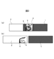
- FIG. 8 shows a member to be joined composed of a CFRP member and an intermediate member made of resin.
- Fig.8 (a) shows the top view of a to-be-joined member
- FIG.8 (b) shows the side view of a to-be-joined member.
- FIG. 8A when the front side of the paper surface is the upper side in the vertical direction of the paper surface, the intermediate member 2 is overlaid on at least the planned joining portion of the CFRP member 1 ′ to be a member to be joined. .
- the CFRP member 1 ′ is a unidirectional prepreg sheet prepared by impregnating a PAN (polyacrylonitrile) -based carbon fiber with a 130 ° C. curable epoxy resin, at 0 ° and 90 ° with respect to the fiber length direction. , 0 °, 90 °, and 0 °, a total of five layers can be laminated, and the intermediate member 2 can be polyethylene terephthalate (PET resin).
- PAN polyacrylonitrile
- PET resin polyethylene terephthalate
- the plate-shaped glass 7 is piled up on the surface of the side which is not in contact with the CFRP member 1 'of the intermediate member 2 of the member to be joined so as to cover all the portions to be joined.
- the CFRP member 1 ′, the intermediate member 2, and the glass 7 may be closely fixed with two clamps 3 with an interval at which laser light can be irradiated.
- FIG. 9 shows a state where the CFRP member, the intermediate member, and the glass are overlapped to join the CFRP member and the intermediate member.
- FIG. 9 is a view of the member to be joined as seen from the side as in FIG. 8B, and the laser beam from the glass 7 side to the CFRP member 1 ′, the intermediate member 2, and the glass 7 that are overlapped and fixed firmly.
- 4 shows a situation where the joint is irradiated by irradiation with 4. Then, the carbon fiber contained in the CFRP member 1 ′ at the welded portion is irradiated with a laser in, for example, the direction of the width a of the joining progress direction shown in FIG. 8 (perpendicular to the paper surface of FIG. 9). Heat generation is performed, and the resin of the CFRP member 1 ′ is melted thereby, and the intermediate member 2 is melted by the propagation of the generated heat to join the two.
- the defocus amount is +50 mm, that is, the position 50 mm below the focal position of the lens for condensing the laser is made to coincide with the surface position of the CFRP member 1 '.
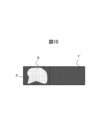
- FIG. 10 shows a CFRP member to which an intermediate member is joined.
- FIG. 10 is a view of the CFRP member to which the intermediate member is joined as viewed from the laser light irradiation side, that is, a plan view of the test piece as in FIG. 1A.
- the side is the upper side
- the intermediate member 2 is superimposed on a part of the CFRP member 1 ′.
- a sound joint 6 portion displayed in white
- the resin component When the glass 7 is not installed on the laser beam 4 irradiation side of the intermediate member 2, the resin component is volatilized by the irradiation of the high-power laser beam, and the resin component is discharged into the optical path of the laser beam. Laser power is lost and bonding is incomplete.
- surroundings of the glass 7 is discharged
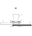
- FIG. 11 shows a member to be joined composed of a metal and a CFRP member to which an intermediate member is joined.
- Fig.11 (a) shows the top view of a to-be-joined member
- FIG.11 (b) shows the side view of a to-be-joined member.
- FIG. 11 (a) shows the top view of a to-be-joined member
- FIG.11 (b) shows the side view of a to-be-joined member.
- the metal plate 1 is overlaid on the surface of the intermediate member 2 on the side not in contact with the CFRP member 1 ′.
- the CFRP member 1 ′, the intermediate member 2, and the metal plate 1 may be closely fixed with two clamps 3 with an interval at which laser light can be irradiated.
- FIG. 12 shows a state in which the CFRP member, the intermediate member, and the metal plate are overlapped to join the CFRP member and the metal plate.
- FIG. 12 is a side view of the member to be joined as in FIG. 11B, and is attached to the CFRP member 1 ′, the intermediate member 2, and the metal plate 1 which are overlapped and firmly fixed from the metal plate 1 side.
- a state in which the surface of the metal plate 1 is irradiated with the laser beam 4 and bonded is shown.
- the member to be joined is irradiated with a laser in the direction of width a in the joining advancing direction shown in FIG. 11 (perpendicular to the paper surface in FIG. 12) under the same conditions as the joining test between the CFRP member and the resin member. Is heated, the intermediate member 2 is melted by the heat conduction, and both are joined.
- the same conditions as the bonding of the CFRP member and the resin member in the above (a) can be adopted.
- the laser output is 3 kW
- the defocus amount is +50 mm
- the bonding speed is 1.5 m / min.
- the position 50 mm below the focal position of the lens that focuses the laser is made to coincide with the surface position of the metal plate 1.
- the joining member between the metal and the CFRP member there is a problem that an electrolytic corrosion reaction occurs from the joining surface, thereby causing local corrosion of the metal, which is obtained by the welding method of the third aspect of the present invention. Since the joining member has an intermediate member made of resin inserted between the metal and the CFRP member, local corrosion of the metal is suppressed.
- the third aspect of the present invention has reached the invention described in the above (3) through the examination process as described above. Necessary requirements and preferable requirements for such the present invention will be described later. .
- the joining method of the metal of the fourth aspect of the present invention and the carbon fiber reinforced resin (CFRP) member (hereinafter referred to as “the joining method of the fourth aspect of the present invention”) is as follows: An intermediate member made of resin and metal are superimposed on the CFRP member in this order, and laser light is irradiated to the joint from the metal side, and each member is one-pass joined at a joining speed of 0.5 to 5.0 m / min. To do.
- an intermediate member made of a resin and a metal are superposed in this order on the CFRP member, and the CFRP member and the metal are joined via the intermediate member by laser beam irradiation from the metal side with only one pass.
- FIG. 11 shows a member to be joined composed of a CFRP member, an intermediate member, and a metal.
- Fig.11 (a) shows the top view of a to-be-joined member
- FIG.11 (b) shows the side view of a to-be-joined member.
- FIG. 11 (a) shows the top view of a to-be-joined member
- FIG.11 (b) shows the side view of a to-be-joined member.
- FIG. 11 (a) shows the top view of a to-be-joined member
- FIG.11 (b) shows the side view of a to-be-joined member.
- FIG. 11 (a) shows the top view of a to-be-joined member
- FIG.11 (b) shows the side view of a to-be-joined member.
- the CFRP member 1 ′, the intermediate member 2, and the metal plate 1 may be closely fixed with two clamps 3 with an interval at which laser light can be
- FIG. 12 shows a state in which the CFRP member, the intermediate member, and the metal plate are overlapped to join the CFRP member and the metal plate.
- FIG. 12 is a side view of the member to be joined as in FIG. 11B, and is attached to the CFRP member 1 ′, the intermediate member 2, and the metal plate 1 which are overlapped and firmly fixed from the metal plate 1 side.
- a state in which the surface of the metal plate 1 is irradiated with the laser beam 4 and bonded is shown.
- the metal is heated to the member to be joined in the direction of the width a in the joining advancing direction shown in FIG. 11 (perpendicular to the plane of FIG. 12) by laser irradiation with only one pass, and the intermediate member 2 is heated by the heat conduction. Melt to join the CFRP member and metal.
- the defocus amount is +50 mm, that is, the position 50 mm below the focal position of the lens for condensing the laser is made to coincide with the surface position of the metal plate 1.
- the intermediate member 2 is not directly irradiated with laser. Therefore, there is little possibility that the resin component volatilizes due to the irradiation of the high-power laser beam. Even if the resin component is volatilized, the resin 1 that has volatilized from the periphery of the metal 1 is discharged by installing the metal 1 on the laser beam 4 irradiation side of the intermediate member 2. The components do not interfere with the laser beam 4, and the laser output can be increased and bonding can be performed at high speed. Therefore, it is possible to efficiently irradiate the laser, heat the metal, melt the intermediate member 2 by the heat conduction, and join the CFRP member and the metal.
- the joining member of a metal and a CFRP member there is a problem that an electrolytic corrosion reaction occurs from the joining surface, thereby causing local corrosion of the metal, which was obtained by the welding method of the fourth aspect of the present invention. Since the joining member has an intermediate member made of resin inserted between the metal and the CFRP member, local corrosion of the metal is suppressed.
- the fourth aspect of the present invention has reached the invention described in the above (4) through the examination process as described above. Necessary requirements and preferable requirements for such the present invention will be described below. .
- the metal to be joined is a metal used in an automobile or the like, and is not particularly limited including the component composition.
- the thickness of a metal is not specifically limited, either.
- the thickness of the metal is preferably 3.5 mm or less.
- An example of such a metal is steel.
- process layers, such as plating, on the metal surface is preferable.
- CFRP member to be joined The CFRP member to be joined is not particularly limited, and can be selected from known CFRP members according to the usage mode. Moreover, as a carbon fiber which comprises a CFRP member, a PAN (polyacrylonitrile) type
- thermosetting resins such as epoxy resin, phenol resin, benzoxazine resin, vinyl ester resin, unsaturated polyester resin, polyethylene, polypropylene resin, polyamide resin, ABS resin, urethane resin
- thermoplastic resins such as resins such as polybutylene terephthalate resin, polyacetal resin, and polycarbonate.
- the resin used as a raw material for the resin member to be joined (or an intermediate member made of resin) is not particularly limited as long as it transmits the laser beam to be used.
- Polyamide resin such as nylon 6 (PA6) ( Examples thereof include polyester resins such as PA) and polyethylene terephthalate (PET), polycarbonate (PC) resins, styrene resins such as ABS, and thermoplastic resins such as acrylic resins (PMMA and the like).
- the resin may be added with a filler that improves characteristics such as a fibrous filler.
- the transmittance of the resin member (or intermediate member) for the laser beam used is preferably 60% or more, and more preferably 80% or more in order to increase the bonding speed.
- the thickness of the resin member (or intermediate member) is preferably 0.2 mm or more and 5.0 mm or less. If the thickness is less than 0.2 mm, the heat capacity is melted to a small extent and bonding may not be possible, and sufficient bonding strength may not be obtained. On the other hand, if the thickness exceeds 5.0 mm, the attenuation of the laser beam is large, and sufficient laser power may not be supplied to the steel sheet, which may prevent bonding.
- the thickness is preferably 1.0 mm or less. If it exceeds 1.0 mm, the resin may not be sufficiently melted by laser irradiation with only one pass.
- Glass to be superimposed on resin member or intermediate member The glass is superimposed on the surface of the resin member (or intermediate member) on the side irradiated with the laser beam opposite to the surface in contact with the metal or CFRP member. This glass discharges the volatile component from the outer periphery of the glass plate so that the volatile resin component does not interfere with the laser beam.
- the glass is not particularly limited as long as it transmits the laser light to be used and does not react with the volatilized resin component, and quartz glass is exemplified.
- the glass transmittance with respect to the laser beam used is preferably 60% or more, and more preferably 90% or more in order to increase the bonding speed. In order to increase the transmittance, it is desirable to polish the front and back surfaces of the glass in parallel.
- the glass thickness is preferably 1.0 mm or more and 5.0 mm or less. If it is less than 1 mm, it may not be able to withstand the applied pressure when gripping with a clamp. In addition, since it is not essential to hold
- the glass is preferably provided with an antireflection film for preventing the reflection of laser light on the surface of the glass that is to be overlapped with the planned joining portion.
- the laser beam may be reflected by about 20%, and by providing an antireflection film on the glass surface, the reflection can be suppressed to about several percent, and the laser energy can be used efficiently. Can be welded at high speed.
- the antireflection film is not particularly limited, and a known antireflection film can be formed according to the wavelength of the laser beam.
- the resin component that volatilizes is discharged from the outer periphery of the glass by the glass so as not to interfere with the laser beam.
- the volatile components discharged from the outer periphery of the glass may be blown and diffused. Thereby, interference with the laser beam of a volatile component can be suppressed further reliably.
- a blower, a fan, a gas jet, or the like can be used as a means for blowing air.
- the shape of the metal, CFRP member, and resin member (or intermediate member) to be joined may be any shape as long as at least the joining location is a plate, and can be any shape such as a rectangular shape, a circular shape, or an elliptical shape when viewed from the laser irradiation surface side.
- the whole may not be a board.
- it may be subjected to bending, pressing, drilling, etc., and includes a flange portion of a member that has been press-molded into a specific shape having a cross-sectional hat shape.
- the intermediate member is provided as an adhesive layer at a location where the metal and the CFRP member are to be joined.
- the intermediate member is used as a member to replace a part of the metal for weight reduction of the component, or the component has various characteristics. It is good also as what is provided as a member for this.
- a shape that can cover at least the metal and the CFRP member to be bonded a shape corresponding to the use mode may be used, and at least the bonding point should be a plate shape, similar to the shape of the metal and the CFRP member. Any shape may be used, and the whole may not be plate-shaped.
- glass should just be able to cover the joining plan location, and is adjusted according to the shape of a metal, a CFRP member, and a resin member (or intermediate member). Covering the planned joining portion covers one or more times the width of the planned joining location, or covering one or more times the condensing area of the laser beam at the joining interface between the metal or CFRP member and the resin member (or intermediate member). That is.
- the laser bonding apparatus used in the bonding method of the present invention is not particularly limited, and a conventional laser bonding apparatus can be employed.
- a remote laser head can also be used for the laser bonding apparatus.
- the laser bonding apparatus includes a laser oscillator, an optical path, a condensing optical system, a drive system, a shield gas system, and the like.
- a laser oscillator a laser such as a CO 2 laser, a YAG laser, a fiber laser, or a DISK laser can be used.
- the laser oscillated by the laser oscillator is guided to the condensing optical system through the optical path.
- the condensing optical system is composed of a parabolic mirror, a condensing lens, and the like, and condenses the transmitted laser.
- the focal position of the laser is variable.
- the metal and the resin member or the CFRP member and the resin member (intermediate member) are joined.
- a predetermined defocus amount may be set and adjusted so that the condensing area of the laser beam is 40.85 mm 2 at the interface.
- the metal is heated and the intermediate member is melted by the heat conduction, so that a desired light collection area can be obtained at the surface position of the metal.
- the defocus amount may be set and adjusted.
- the condensing shape can be rectangular, elliptical, or the like.
- the laser beam is irradiated onto the members to be joined, and the drive system is moved to advance the joining.
- the condensing optical system or the member to be joined may be moved.
- laser light may be scanned with a galvanometer mirror.
- the laser bonding method when the laser is irradiated through the glass (first to third aspects), the metal and the resin member, the CFRP member and the resin member (intermediate member) are overlapped, and the resin member (intermediate member) Glass is arranged on the laser irradiation surface side of the laser beam to increase the laser output and increase the bonding speed. At this time, it is possible to perform the bonding under conditions of a laser output of 2 to 4 kW, a condensing area of 20 to 60 mm 2 , and a bonding speed of 0.5 to 5.0 m / min.
- the same conditions as in the case where the laser passes through the glass and joins the above members can be employed.
- the condensing shape is not particularly limited, such as a rectangle or an ellipse.
- the bonding speed is less than 0.5 m / min, the output is low and the amount of volatilization of the resin is small. Therefore, the volatilized resin does not interfere with the laser beam, and the metal or CFRP member and the resin member (intermediate member ).
- the bonding speed exceeds 5 m / min, a high-power laser is required, and when such a high-power laser is used, the resin member or metal is affected by heat and the characteristics may change.
- the bonding strength is further improved.
- the method for pressing and fixing the metal, the CRFP member, the resin member (intermediate member), and the glass is not particularly limited, and examples thereof include a method of pressing and fixing with a clamp or the like.
- the conditions in the examples are one example of conditions used for confirming the feasibility and effects of the present invention, and the present invention is based on this one example of conditions. It is not limited.
- the present invention can adopt various conditions as long as the object of the present invention is achieved without departing from the gist of the present invention.
- the metal to be joined is a steel plate having a thickness of 1.4 mm
- the resin member to be joined is a PET resin having a thickness of 2.0 mm
- both have a width a in the joining progress direction in FIG. 4 of 30 mm.
- the lengths b1 and b2 in the direction perpendicular to the joining direction were 150 mm.
- the glass was a circular plate with a diameter of 54.6 mm and a plate thickness of 1.5 mm, and quartz glass having an antireflection film was used. Then, as shown in FIG.
- a part of the steel plate and a part of the resin member are overlapped, the width a of the overlapping portion in the joining progress direction is set to 30 mm, and the length b3 of the overlapping portion in the direction perpendicular to the joining progress direction is set.
- the thickness was 45 to 50 mm.
- a glass plate was placed on the resin member so as to cover the entire overlapped portion, and the steel plate, the resin member, and the glass were closely fixed with two clamps at an interval where laser light could be irradiated.
- the laser As the laser, a semiconductor laser having a wavelength of 940 nm was used.
- the transmittance of the resin member with respect to the laser beam was 86%, and the transmittance of the glass with respect to the laser beam was 93%.
- the resin member surface in contact with the glass is irradiated with laser through the glass, and the irradiation position of the laser light is moved in the a direction at a bonding speed of 1.5 m / min.
- the defocus amount +50 mm was set in the optical axis direction of the laser light with respect to the joint portion.
- the condensing size is estimated to be a rectangle of 4.3 mm ⁇ 9.5 mm and a condensing area of 40.85 mm 2 .
- Comparative Example 1-2 except that glass was not used, a metal and a resin member were laser-bonded using the same material and bonding conditions as those of Invention Example 1 to obtain a test piece 1-2. Further, as Comparative Example 1-3, the metal and the resin member were laser-bonded with the same material and bonding conditions as the inventive example, except that the glass plate was not used and the bonding speed was 0.3 m / min. A test piece 1-3 was obtained.
- FIG. 13 shows the shear tensile strength of the test piece.
- the test piece 1-1 bonded with glass at a bonding speed of 1.5 m / min is sheared compared to the test piece 1-2 bonded at a bonding speed of 1.5 m / min without using a glass plate. High tensile strength.
- the test piece 1-1 had the same shear tensile strength as that of the test piece 1-3 joined without a glass at a joining speed of 0.3 m / min. From this, it was found that by joining the glass plate on the resin member and performing laser bonding, a bonded portion with high bonding strength can be obtained even when the bonding speed is increased.
- the CFRP member to be joined is a plate having a plate thickness of 1.4 mm
- the resin member to be joined is PET resin having a plate thickness of 2.0 mm, both of which have a width a in the joining progress direction in FIG. 30 mm and lengths b1 and b2 perpendicular to the joining direction were 150 mm.
- the glass was a circular plate with a diameter of 54.6 mm and a plate thickness of 1.5 mm, and quartz glass having an antireflection film was used.
- a part of the CFRP member and a part of the resin member are overlapped, the width a of the overlapping portion in the joining progress direction is set to 30 mm, and the length b3 of the overlapping portion in the direction perpendicular to the joining progress direction. was 45 to 50 mm.
- a glass plate was placed on the resin member so as to cover the entire overlapped portion, and the CFRP member, the resin member, and the glass were closely fixed with two clamps at an interval where laser light could be irradiated.
- the laser As the laser, a semiconductor laser having a wavelength of 940 nm was used.
- the transmittance of the resin member with respect to the laser beam was 86%, and the transmittance of the glass with respect to the laser beam was 93%.
- the resin member surface in contact with the glass is irradiated with laser through the glass, and the irradiation position of the laser beam is moved in the a direction at a bonding speed of 1.5 m / min.
- a test piece 2-1 of Invention Example 2 was obtained.
- the defocus amount +50 mm was set in the optical axis direction of the laser light with respect to the joint portion.
- the condensing size is estimated to be a rectangle of 4.3 mm ⁇ 9.5 mm and a condensing area of 40.85 mm 2 .
- Comparative Example 2-2 a CFRP member and a resin member were laser-bonded using the same materials and bonding conditions as in the inventive example except that glass was not used, to obtain a test piece 2-2.
- FIG. 14 shows the shear tensile strength of the test piece.
- the test piece 2-1 joined using glass had a very high shear tensile strength compared to the test piece 2-2 joined without using a glass plate. From this, it was found that by joining the glass on the resin member and performing laser bonding, a bonded portion with high bonding strength can be obtained even if the bonding speed is increased.
- the metal to be joined is a steel plate with a thickness of 1.4 mm
- the CFRP member to be joined is a plate with a thickness of 1.0 mm
- the intermediate member made of resin to be joined has a thickness of 2.0 mm. 11 having a width a in the joining progression direction of 30 mm, a length b1 in the direction perpendicular to the joining progression direction of 45 to 50 mm, and b2 and b3 of 150 mm.
- the width a of the overlapping portion in the joining progress direction is set to 30 mm, and the length of the overlapping portion in the direction perpendicular to the joining progress direction is 45 to 50 mm. It was. Then, a glass plate was placed on the intermediate member so as to cover the entire overlapping portion, and the CFRP member, the intermediate member, and the glass were closely fixed with two clamps at an interval where laser light could be irradiated.
- the glass was a circular plate with a diameter of 54.6 mm and a plate thickness of 1.5 mm, and quartz glass having an antireflection film was used.
- the laser As the laser, a semiconductor laser having a wavelength of 940 nm was used.
- the transmittance of the intermediate member with respect to the laser beam was 86%, and the transmittance of the glass with respect to the laser beam was 93%.
- the resin member surface in contact with the glass is irradiated with laser through the glass, and the irradiation position of the laser beam is moved in the a direction at a bonding speed of 1.5 m / min, so that the CFRP member and the intermediate member And joined.
- the defocus amount +50 mm was set in the optical axis direction of the laser light with respect to the joint portion.
- the condensing size is estimated to be a rectangle of 4.3 mm ⁇ 9.5 mm and a condensing area of 40.85 mm 2 .
- metal is overlapped on the CFRP member to which the intermediate member is bonded, the width a of the overlapping portion in the bonding progress direction is set to 30 mm, and the length of the overlapping portion in the direction perpendicular to the bonding progress direction is set to 45 mm. ⁇ 50 mm. Then, the metal, the CFRP member, and the intermediate member were tightly fixed by two clamps with an interval at which the laser beam could be irradiated.
- the laser is a semiconductor laser with a wavelength of 940 nm, the laser output is 3 kW, the metal surface is irradiated with laser light, and the irradiation position of the laser light is moved in the a direction at a bonding speed of 1.5 m / min.
- the CFRP member to which the intermediate member was bonded was bonded to obtain a test piece 3-1 of Invention Example 3.
- the defocus amount was set to +50 mm in the optical axis direction of the laser light with respect to the metal surface.
- the condensing size is estimated to be a rectangle of 4.3 mm ⁇ 9.5 mm and a condensing area of 40.85 mm 2 .
- Comparative Example 3-2 without using the intermediate member, the metal and the CFRP member are directly overlapped with the same material and bonding conditions as those of the test piece 3-1, and the laser beam is irradiated from the metal side and bonded. A test piece 3-2 was obtained.
- test piece 3-1 had a tensile strength of 600 N, whereas the test piece 3-2 had the metal and the CFRP member peeled off simply by being clamped to the tensile tester.
- the metal to be joined is a steel plate having a thickness of 1.4 mm
- the CFRP member to be joined is a plate having a thickness of 1.0 mm
- the intermediate member made of resin to be joined has a thickness of 1.0 mm. 11 having a width a in the joining progression direction of 30 mm, a length b1 in the direction perpendicular to the joining progression direction of 45 to 50 mm, and b2 and b3 of 150 mm.
- the width a of the overlapping portion in the joining progress direction is set to 30 mm, and the length of the overlapping portion in the direction perpendicular to the joining progress direction is 45. ⁇ 50 mm.
- the CFRP member, the intermediate member, and the metal were tightly fixed by two clamps with an interval at which the laser beam could be irradiated.
- the laser As the laser, a semiconductor laser having a wavelength of 940 nm was used, the laser power was irradiated to a metal surface with a laser output of 3 kW, and the irradiation position of the laser light was moved only by one pass in the a direction at a bonding speed of 1.5 m / min. As a result, the metal was heated, the intermediate member was melted by the heat conduction, and the CFRP member and the metal were joined to obtain a test piece 4-1 of Invention Example 4. In laser light irradiation, the defocus amount was set to +50 mm in the optical axis direction of the laser light with respect to the metal surface.
- the condensing size is estimated to be a rectangle of 4.3 mm ⁇ 9.5 mm and a condensing area of 40.85 mm 2 .
- Comparative Example 4-2 without using an intermediate member, the metal and the CFRP member are directly overlapped with the same material and bonding conditions as those of the test piece 4-1, and the laser beam is irradiated from the metal side and bonded. A test piece 4-2 was obtained.
- test piece 4-1 had a tensile strength of 600 N, whereas the test piece 4-2 had the metal and the CFRP member peeled off simply by being clamped to the tensile tester.
- the bonding between the metal and the resin member, the bonding between the CFRP member and the resin member, and the bonding between the metal and the resin member through the intermediate member can be realized at high speed, and the bonding strength thereof can be increased. Are better. Furthermore, the metal and the resin member can be joined via the intermediate member by one-pass welding. Therefore, the present invention has high industrial applicability.
Landscapes
- Engineering & Computer Science (AREA)
- Mechanical Engineering (AREA)
- Physics & Mathematics (AREA)
- Optics & Photonics (AREA)
- Toxicology (AREA)
- Health & Medical Sciences (AREA)
- Electromagnetism (AREA)
- Inorganic Chemistry (AREA)
- Chemical & Material Sciences (AREA)
- Crystallography & Structural Chemistry (AREA)
- Lining Or Joining Of Plastics Or The Like (AREA)
- Laser Beam Processing (AREA)
- Manufacture Of Macromolecular Shaped Articles (AREA)
- Materials Engineering (AREA)
Abstract
Description
特許文献2に開示の技術は、金属の光吸収率に左右されず、高強度かつ均一に樹脂と金属とをレーザ接合できるため、有効な技術であるが、接合速度について記載も示唆もない。
特許文献3に開示の技術は、接合速度が5mm/sであり、生産効率が十分に高いとはいえない。特許文献4では、接合速度について記載も示唆もない。
しかしながら、接着剤技術では、乾燥・硬化時間が必要であり、また、有機溶剤の気散等の環境負荷の問題が指摘されており、振動溶着、超音波溶着、摩擦溶着技術では、振動による製品の損傷の問題が指摘されている。また、熱板溶着技術では、接着時間が短く量産に適しており、振動による損傷も少ないが、熱板を直接被接合部材に接触させるため、熱板を取り去る際に、溶融した樹脂が熱板に付着して糸引き現象が発生する問題がある。
(1)金属と樹脂部材とを重ね合わせて樹脂部材側からレーザ光を照射して接合する接合方法において、前記金属に、レーザ光が透過する前記樹脂部材とガラスを、この順で重ね合わせ、前記樹脂部材側から前記ガラスを介して前記レーザ光を前記金属と前記樹脂部材の重ね合わされた接合箇所に照射して、接合速度0.5m~5.0m/minで接合することを特徴とする金属と樹脂部材の接合方法。
(2)炭素繊維強化樹脂部材と樹脂部材とを重ね合わせて樹脂部材側からレーザ光を照射して接合する接合方法において、
前記炭素繊維強化樹脂部材に、レーザ光が透過する前記樹脂部材とガラスを、この順で重ね合わせ、前記樹脂部材側から前記ガラスを介して前記レーザ光を前記炭素繊維強化樹脂部材と前記樹脂部材の重ね合わされた接合箇所に照射して、接合速度0.5m~5.0m/minで接合することを特徴とする炭素繊維強化樹脂部材と樹脂部材の接合方法。
(3)樹脂よりなる中間部材を介して金属と炭素繊維強化樹脂部材とをレーザ光を照射して接合する方法において、
前記炭素繊維強化樹脂部材とレーザ光が透過する樹脂よりなる前記中間部材とを接合し、次いで、当該中間部材と前記金属とを接合するものであり、
前記炭素繊維強化樹脂部材と前記中間部材との接合の際、前記炭素繊維強化樹脂部材に、前記中間部材とガラスを、この順で重ね合わせ、当該中間部材側から当該ガラスを介してレーザ光を当該炭素繊維強化樹脂部材と当該中間部材の重ね合わされた接合箇所に照射して、接合速度0.5m~5.0m/minで接合し、
前記中間部材と前記金属の接合の際、前記中間部材の表面に、前記金属を重ね合わせ、接合箇所の金属表面にレーザ光を照射して当該金属を加熱して、接合速度0.5m~5.0m/minで接合する
ことを特徴とする中間部材を介して金属と炭素繊維強化樹脂部材の接合方法。
(4)
樹脂よりなる中間部材を介して金属と炭素繊維強化樹脂部材とをワンパスのみのレーザ光照射により接合する方法において、
前記炭素繊維強化樹脂部材に、前記中間部材と前記金属を、この順で重ね合わせ、当該金属側からレーザ光を当該金属と当該炭素繊維強化樹脂部材と当該中間部材の重ね合わされた接合箇所に照射して、接合速度0.5m~5.0m/minでワンパス接合する
ことを特徴とする中間部材を介した金属と炭素繊維強化樹脂部材との接合方法。
次に、本発明の第1の態様の接合法に至った検討の経緯について説明するとともに、本発明の第1の態様の接合法について説明する。
次に、本発明の第2の態様の接合法に至った検討の経緯について説明するとともに、本発明の第2の態様の接合法について説明する。
(a)まず、レーザ光を照射して、接合速度0.5m~5.0m/minで、CFRP部材と樹脂よりなる中間部材とを接合し、
(b)次いで、レーザ光を照射して、接合速度0.5m~5.0m/minで、金属と、中間部材とを接合する
方法である。
(b)において、金属と、中間部材とを重ね合わせ、当該金属側からレーザ光を照射して金属を加熱し、金属と中間部材とを接合する。
まず、CFRP部材に樹脂よりなる中間部材とガラスをこの順で重ね合わせ、ガラスと接した中間部材面にガラスを通してレーザ光を照射してCFRP部材と中間部材とを接合する。
次に、金属と、中間部材が接合されたCFRP部材とを重ね合わせ、金属側からレーザ光を照射して金属と中間部材とを接合する。
CFRP部材に、樹脂よりなる中間部材と金属を、この順で重ね合わせ、金属側からレーザ光を接合箇所に照射して、接合速度0.5m~5.0m/minで、各部材をワンパス接合するものである。
接合される金属は、自動車等で使用される金属であり、成分組成も含め、特に限定されるものでない。また、樹脂部材側からレーザ光を照射する場合(第1の態様)、金属の表面を加熱するため、金属の厚さも、特に限定されるものでない。金属側からレーザ光を照射する場合(第3の態様、第4の態様)、中間部材との非接触面側からレーザ光を照射して、熱伝導により中間部材との接触面を加熱し、中間部材を溶融させるため、金属の厚さは3.5mm以下とすることが好ましい。このような金属として、鋼材が例示される。また、金属の表面にめっきなどの処理層を有さないものが好ましい。
接合されるCFRP部材は、特に限定されるものでなく、使用態様によって公知のCFRP部材から選択することができる。また、CFRP部材を構成する炭素繊維としては、PAN(ポリアクリルニトリル)系炭素繊維、ピッチ系炭素繊維等が例示される。特に、PAN系炭素繊維は、強度、弾性率、伸度のバランスが良い。また、CFRP部材を構成する樹脂としては、エポキシ樹脂、フェノール樹脂、ベンゾオキサジン樹脂、ビニルエステル樹脂、不飽和ポリエステル樹脂等の熱硬化性樹脂や、ポリエチレン、ポリプロピレン樹脂、ポリアミド樹脂、ABS樹脂、ウレタン樹脂、ポチブチレンテレフタレート樹脂、ポリアセタール樹脂、ポリカーボネート等の樹脂等の熱可塑性樹脂が例示される。
接合される樹脂部材(または樹脂よりなる中間部材)の原料となる樹脂は、使用するレーザ光を透過するものであれば、特に限定されるものでなく、ナイロン6(PA6)等のポリアミド樹脂(PA)、ポリエチレンテレフタレート(PET)等のポリエステル樹脂、ポリカーボネート(PC)樹脂、ABS等のスチレン系樹脂、アクリル系樹脂(PMMA等)等の熱可塑性樹脂が例示される。なお、樹脂は、繊維状充填剤等の特性を向上させる充填剤を添加しているものでもよい。
また、第4の態様では、ワンパス接合で、金属を加熱して、その熱伝導により中間部材を溶融するため、1.0mm以下の厚みとすることが好ましい。1.0mmを超えるとワンパスのみのレーザ照射で十分に樹脂を溶融できないおそれがある。
ガラスは、樹脂部材(または中間部材)の金属またはCFRP部材と接触する面と反対側のレーザ光が照射される側の面に重ね合わされる。このガラスは、揮発する樹脂成分がレーザ光と干渉しないように、揮発成分をガラス板の外周から排出させるものである。ガラスは、使用するレーザ光を透過し、揮発した樹脂成分と反応しないものであれば、特に限定されるものでなく、石英ガラスが例示される。
接合される金属、CFRP部材及び樹脂部材(または中間部材)の形状は、少なくとも接合箇所が板状であればよく、レーザ照射面側からみたとき、矩形状、円形状、楕円形状などいかなる形状でもよく、また、全体が板でなくともよい。例えば、曲げ加工、プレス加工、穴あけ加工等が施されていてもよく、断面ハット形の特定の形状にプレス成型等された部材のフランジ部等を含むものである。
本発明の接合方法で用いるレーザ接合装置は、特に限定されるものでなく、従来のレーザ接合装置を採用することができる。また、レーザ接合装置に、リモートレーザヘッドを用いることもできる。
レーザ接合方法では、レーザがガラスを透過して照射される場合(第1~3の態様)、金属と樹脂部材、CFRP部材と樹脂部材(中間部材)とを重ね合わせ、樹脂部材(中間部材)のレーザ照射面側にガラスを配置して、レーザ出力を高くし、接合速度を速くして接合する。この際、レーザ出力2~4kW、集光面積20~60mm2、接合速度0.5~5.0m/minの接合条件で行うことができ、従来に比べて非常に高速での接合が実現される。レーザが金属に照射される場合(第3の態様、第4の態様)も、レーザがガラスを透過して上記部材の接合をする場合と同等の条件を採用することができる。集光形状は矩形や楕円形等、特に限定されるものではない。また、接合速度が0.5m/min未満であれば、出力が低く樹脂の揮発量が少ないため、揮発した樹脂によるレーザ光への干渉は発生せず、金属またはCFRP部材と樹脂部材(中間部材)との接合ができる。接合速度が5m/minを超えると高出力なレーザが必要となり、そのような高出力のレーザを用いると樹脂部材または金属が熱による影響を受け、その特性が変化してしまうおそれがある。
まず、接合される金属は、板厚1.4mmの鋼板であり、接合される樹脂部材は、板厚2.0mmのPET樹脂であり、両者とも、図4における接合進行方向の幅aが30mm、接合進行方向に垂直方向の長さb1及びb2が150mmのものを用いた。ガラスは、直径φ54.6mm、板厚1.5mmの円形板状であり、反射防止膜を有する石英ガラスを用いた。そして、図4に示すように、鋼板の一部と樹脂部材の一部とを重ね、重なり部分の接合進行方向の幅aを30mmとし、重なり部分の接合進行方向と垂直方向の長さb3を45~50mmとした。そして、重なり部分全体を覆うようにガラス板を樹脂部材上に載せ、レーザ光を照射できる間隔をあけて2つのクランプにて鋼板、樹脂部材及びガラスを密着固定した。
まず、接合されるCFRP部材は、板厚1.4mmの板であり、接合される樹脂部材は、板厚2.0mmのPET樹脂であり、両者とも、図4における接合進行方向の幅aが30mm、接合進行方向に垂直方向の長さb1及びb2が150mmのものを用いた。ガラスは、直径φ54.6mm、板厚1.5mmの円形板状であり、反射防止膜を有する石英ガラスを用いた。
まず、接合される金属は、板厚1.4mmの鋼板であり、接合されるCFRP部材は、板厚1.0mmの板であり、接合される樹脂よりなる中間部材は、板厚2.0mmのPET樹脂であり、図11における接合進行方向の幅aが30mm、接合進行方向に垂直方向の長さb1が45~50mm、b2及びb3が150mmのものを用いた。
まず、接合される金属は、板厚1.4mmの鋼板であり、接合されるCFRP部材は、板厚1.0mmの板であり、接合される樹脂よりなる中間部材は、板厚1.0mmのPET樹脂であり、図11における接合進行方向の幅aが30mm、接合進行方向に垂直方向の長さb1が45~50mm、b2及びb3が150mmのものを用いた。
1’ CFRP部材
2 樹脂部材、中間部材
3 クランプ
4 レーザ光
5 溶融部
6 接合部
7 ガラス
a 接合進行方向の幅
b1 樹脂の接合進行方向に垂直方向の長さ
b2 金属の接合進行方向に垂直方向の長さ
b3 重なり部分の接合進行方向と垂直方向の長さ
Claims (4)
- 金属と樹脂部材とを重ね合わせて樹脂部材側からレーザ光を照射して接合する接合方法において、
前記金属に、レーザ光が透過する前記樹脂部材とガラスを、この順で重ね合わせ、前記樹脂部材側から前記ガラスを介して前記レーザ光を前記金属と前記樹脂部材の重ね合わされた接合箇所に照射して、接合速度0.5m~5.0m/minで接合することを特徴とする金属と樹脂部材の接合方法。
- 炭素繊維強化樹脂部材と樹脂部材とを重ね合わせて樹脂部材側からレーザ光を照射して接合する接合方法において、
前記炭素繊維強化樹脂部材に、レーザ光が透過する前記樹脂部材とガラスを、この順で重ね合わせ、前記樹脂部材側から前記ガラスを介して前記レーザ光を前記炭素繊維強化樹脂部材と前記樹脂部材の重ね合わされた接合箇所に照射して、接合速度0.5m~5.0m/minで接合することを特徴とする炭素繊維強化樹脂部材と樹脂部材の接合方法。
- 樹脂よりなる中間部材を介して金属と炭素繊維強化樹脂部材とをレーザ光を照射して接合する方法において、
前記炭素繊維強化樹脂部材とレーザ光が透過する樹脂よりなる前記中間部材とを接合し、次いで、当該中間部材と前記金属とを接合するものであり、
前記炭素繊維強化樹脂部材と前記中間部材との接合の際、前記炭素繊維強化樹脂部材に、前記中間部材とガラスを、この順で重ね合わせ、当該中間部材側から当該ガラスを介してレーザ光を当該炭素繊維強化樹脂部材と当該中間部材の重ね合わされた接合箇所に照射して、接合速度0.5m~5.0m/minで接合し、
前記中間部材と前記金属の接合の際、前記中間部材の表面に、前記金属を重ね合わせ、接合箇所の金属表面にレーザ光を照射して当該金属を加熱して、接合速度0.5m~5.0m/minで接合する
ことを特徴とする中間部材を介した金属と炭素繊維強化樹脂部材との接合方法。
- 樹脂よりなる中間部材を介して金属と炭素繊維強化樹脂部材とをワンパスのみのレーザ光照射により接合する方法において、
前記炭素繊維強化樹脂部材に、前記中間部材と前記金属を、この順で重ね合わせ、当該金属側からレーザ光を当該金属と当該炭素繊維強化樹脂部材と当該中間部材の重ね合わされた接合箇所に照射して、接合速度0.5m~5.0m/minでワンパス接合する
ことを特徴とする中間部材を介した金属と炭素繊維強化樹脂部材との接合方法。
Priority Applications (9)
| Application Number | Priority Date | Filing Date | Title |
|---|---|---|---|
| EP16772891.4A EP3278958A4 (en) | 2015-03-30 | 2016-03-29 | Method for bonding metal, resin member and carbon fiber-reinforced resin member |
| MX2017012081A MX2017012081A (es) | 2015-03-30 | 2016-03-29 | Metodo para unir metal, miembro de plastico y miembro de plastico reforzado con fibra de carbono. |
| KR1020177026770A KR102132702B1 (ko) | 2015-03-30 | 2016-03-29 | 금속, 수지 부재 및 탄소 섬유 강화 수지 부재의 접합 방법 |
| CN201680013988.2A CN107428090B (zh) | 2015-03-30 | 2016-03-29 | 金属、树脂部件以及碳纤维强化树脂部件的接合方法 |
| CA2980530A CA2980530C (en) | 2015-03-30 | 2016-03-29 | Method of joining metal, plastic member, and carbon fiber reinforced plastic member by means of a laser beam |
| BR112017020601-3A BR112017020601A2 (ja) | 2015-03-30 | 2016-03-29 | A joining method of metal, a resin member, and a carbon fiber strengthening resin member |
| JP2017510056A JP6817191B2 (ja) | 2015-03-30 | 2016-03-29 | 金属、樹脂部材及び炭素繊維強化樹脂部材の接合方法 |
| US15/563,503 US10654221B2 (en) | 2015-03-30 | 2016-03-29 | Method of joining metal, plastic member, and carbon fiber reinforced plastic member |
| RU2017133863A RU2681637C1 (ru) | 2015-03-30 | 2016-03-29 | Способ соединения металлического элемента, пластикового элемента и пластикового элемента, армированного углеродным волокном |
Applications Claiming Priority (6)
| Application Number | Priority Date | Filing Date | Title |
|---|---|---|---|
| JP2015-069268 | 2015-03-30 | ||
| JP2015069268 | 2015-03-30 | ||
| JP2015185205 | 2015-09-18 | ||
| JP2015185179 | 2015-09-18 | ||
| JP2015-185205 | 2015-09-18 | ||
| JP2015-185179 | 2015-09-18 |
Publications (1)
| Publication Number | Publication Date |
|---|---|
| WO2016159010A1 true WO2016159010A1 (ja) | 2016-10-06 |
Family
ID=57006817
Family Applications (1)
| Application Number | Title | Priority Date | Filing Date |
|---|---|---|---|
| PCT/JP2016/060246 Ceased WO2016159010A1 (ja) | 2015-03-30 | 2016-03-29 | 金属、樹脂部材及び炭素繊維強化樹脂部材の接合方法 |
Country Status (10)
| Country | Link |
|---|---|
| US (1) | US10654221B2 (ja) |
| EP (1) | EP3278958A4 (ja) |
| JP (2) | JP6817191B2 (ja) |
| KR (1) | KR102132702B1 (ja) |
| CN (1) | CN107428090B (ja) |
| BR (1) | BR112017020601A2 (ja) |
| CA (1) | CA2980530C (ja) |
| MX (1) | MX2017012081A (ja) |
| RU (1) | RU2681637C1 (ja) |
| WO (1) | WO2016159010A1 (ja) |
Cited By (1)
| Publication number | Priority date | Publication date | Assignee | Title |
|---|---|---|---|---|
| DE102022106844A1 (de) | 2021-03-25 | 2022-09-29 | Toyota Boshoku Kabushiki Kaisha | Verbundelement, sitz für ein automobil und komponente für ein automobil |
Families Citing this family (5)
| Publication number | Priority date | Publication date | Assignee | Title |
|---|---|---|---|---|
| TWI700316B (zh) * | 2019-03-29 | 2020-08-01 | 日商Ihi股份有限公司 | 金屬樹脂接合方法 |
| WO2020202242A1 (ja) | 2019-03-29 | 2020-10-08 | 株式会社Ihi | 金属樹脂接合方法 |
| CN115666908A (zh) * | 2020-05-19 | 2023-01-31 | 巴斯夫欧洲公司 | 一种金属-聚合物复合零件及其制造方法 |
| RU2752905C1 (ru) * | 2020-09-09 | 2021-08-11 | Общество с Ограниченной Ответственностью "АРМЗ СЕРВИС" | Способ соединения и разъединения труб лазерной сваркой |
| KR20250172004A (ko) | 2024-05-31 | 2025-12-09 | 서울과학기술대학교 산학협력단 | 탄소 섬유 강화 플라스틱과 금속의 접합 방법 |
Citations (6)
| Publication number | Priority date | Publication date | Assignee | Title |
|---|---|---|---|---|
| JP2003001455A (ja) * | 2001-06-15 | 2003-01-08 | Matsushita Electric Ind Co Ltd | 金属と樹脂との接合方法及び装置、制振鋼板の製造方法 |
| JP2005064275A (ja) * | 2003-08-13 | 2005-03-10 | Shin Etsu Polymer Co Ltd | 収納容器及びその製造方法 |
| JP2010076437A (ja) * | 2008-08-29 | 2010-04-08 | Toray Ind Inc | 熱可塑性樹脂組成物からなる成形体と金属の複合体の製造方法 |
| JP2010125653A (ja) * | 2008-11-26 | 2010-06-10 | Nitto Denko Corp | シート接合体作製方法 |
| JP2013129177A (ja) * | 2011-12-22 | 2013-07-04 | Teijin Ltd | 接合体の製造方法 |
| JP2014076545A (ja) * | 2012-10-09 | 2014-05-01 | Imasen Electric Ind Co Ltd | 炭素繊維強化樹脂の強度補強方法 |
Family Cites Families (21)
| Publication number | Priority date | Publication date | Assignee | Title |
|---|---|---|---|---|
| JPS535003B2 (ja) | 1972-08-14 | 1978-02-23 | ||
| JPH06101732A (ja) | 1992-09-17 | 1994-04-12 | Kobe Steel Ltd | 複合構造の衝撃吸収用部材 |
| US6220673B1 (en) | 1999-07-12 | 2001-04-24 | Colgate-Palmolive Company | Laser joining toothbrush heads to handles |
| JP2004076545A (ja) * | 2002-08-14 | 2004-03-11 | Hakuo Kk | ガラス窓等の断熱、結露防止構造 |
| US6884371B2 (en) | 2003-03-06 | 2005-04-26 | 3M Innovative Properties Company | Method of making retroreflective sheeting and articles |
| JP2005119051A (ja) | 2003-10-14 | 2005-05-12 | Denso Corp | 樹脂成形品およびその製造方法 |
| US7744804B2 (en) * | 2004-03-12 | 2010-06-29 | Orient Chemical Industries, Ltd. | Laser-transmissible composition and method of laser welding |
| JP2008531355A (ja) * | 2005-03-03 | 2008-08-14 | イー・アイ・デュポン・ドウ・ヌムール・アンド・カンパニー | レーザ溶接装置およびレーザ溶接方法 |
| CN1923897A (zh) * | 2005-09-01 | 2007-03-07 | 东方化学工业株式会社 | 激光透过性着色树脂组合物及其相关技术 |
| JP4125315B2 (ja) * | 2005-10-11 | 2008-07-30 | キヤノン株式会社 | 露光装置及びデバイス製造方法 |
| DE102007003357A1 (de) | 2007-01-17 | 2008-07-24 | Airbus Deutschland Gmbh | Verfahren zum Verbinden eines thermoplastischen Materials mit einem Faserverbundmaterial |
| JP4873482B2 (ja) | 2007-02-28 | 2012-02-08 | 国立大学法人大阪大学 | 複数のレーザ光源を用いた金属樹脂接合方法及び金属樹脂複合体 |
| JP5233991B2 (ja) | 2007-03-27 | 2013-07-10 | コニカミノルタアドバンストレイヤー株式会社 | 樹脂製部材の接合方法 |
| JP5305003B2 (ja) | 2008-12-09 | 2013-10-02 | トヨタ自動車株式会社 | レーザ接合装置 |
| JP2011073191A (ja) | 2009-09-29 | 2011-04-14 | Taisei Plas Co Ltd | Cfrpと被着材の接合体及びその製造方法 |
| JP5835945B2 (ja) * | 2010-08-11 | 2015-12-24 | 株式会社日立製作所 | レーザ接合方法 |
| JP5894462B2 (ja) * | 2012-02-27 | 2016-03-30 | 早川ゴム株式会社 | レーザー接合用中間部材及びレーザー光を用いた接合方法 |
| JP5838116B2 (ja) | 2012-04-11 | 2015-12-24 | 株式会社日立製作所 | レーザ接合方法 |
| JP6343116B2 (ja) * | 2012-05-31 | 2018-06-13 | 住友ゴム工業株式会社 | ゴルフクラブヘッド及びその製造方法 |
| JP5629025B2 (ja) | 2013-01-23 | 2014-11-19 | デクセリアルズ株式会社 | 親水性積層体、及びその製造方法、防汚用積層体、物品、及びその製造方法、並びに防汚方法 |
| JP2015131394A (ja) | 2014-01-09 | 2015-07-23 | 東レ株式会社 | 繊維強化熱可塑性樹脂一体化構造体 |
-
2016
- 2016-03-29 CA CA2980530A patent/CA2980530C/en active Active
- 2016-03-29 US US15/563,503 patent/US10654221B2/en active Active
- 2016-03-29 CN CN201680013988.2A patent/CN107428090B/zh active Active
- 2016-03-29 RU RU2017133863A patent/RU2681637C1/ru active
- 2016-03-29 MX MX2017012081A patent/MX2017012081A/es unknown
- 2016-03-29 KR KR1020177026770A patent/KR102132702B1/ko active Active
- 2016-03-29 EP EP16772891.4A patent/EP3278958A4/en not_active Withdrawn
- 2016-03-29 WO PCT/JP2016/060246 patent/WO2016159010A1/ja not_active Ceased
- 2016-03-29 BR BR112017020601-3A patent/BR112017020601A2/ja not_active Application Discontinuation
- 2016-03-29 JP JP2017510056A patent/JP6817191B2/ja active Active
-
2019
- 2019-05-29 JP JP2019100509A patent/JP6773175B2/ja active Active
Patent Citations (6)
| Publication number | Priority date | Publication date | Assignee | Title |
|---|---|---|---|---|
| JP2003001455A (ja) * | 2001-06-15 | 2003-01-08 | Matsushita Electric Ind Co Ltd | 金属と樹脂との接合方法及び装置、制振鋼板の製造方法 |
| JP2005064275A (ja) * | 2003-08-13 | 2005-03-10 | Shin Etsu Polymer Co Ltd | 収納容器及びその製造方法 |
| JP2010076437A (ja) * | 2008-08-29 | 2010-04-08 | Toray Ind Inc | 熱可塑性樹脂組成物からなる成形体と金属の複合体の製造方法 |
| JP2010125653A (ja) * | 2008-11-26 | 2010-06-10 | Nitto Denko Corp | シート接合体作製方法 |
| JP2013129177A (ja) * | 2011-12-22 | 2013-07-04 | Teijin Ltd | 接合体の製造方法 |
| JP2014076545A (ja) * | 2012-10-09 | 2014-05-01 | Imasen Electric Ind Co Ltd | 炭素繊維強化樹脂の強度補強方法 |
Non-Patent Citations (1)
| Title |
|---|
| See also references of EP3278958A4 * |
Cited By (2)
| Publication number | Priority date | Publication date | Assignee | Title |
|---|---|---|---|---|
| DE102022106844A1 (de) | 2021-03-25 | 2022-09-29 | Toyota Boshoku Kabushiki Kaisha | Verbundelement, sitz für ein automobil und komponente für ein automobil |
| US12337739B2 (en) | 2021-03-25 | 2025-06-24 | Toyota Boshoku Kabushiki Kaisha | Composite member, seat for automobile, and component for automobile |
Also Published As
| Publication number | Publication date |
|---|---|
| JPWO2016159010A1 (ja) | 2017-12-28 |
| US10654221B2 (en) | 2020-05-19 |
| CN107428090A (zh) | 2017-12-01 |
| JP2019142240A (ja) | 2019-08-29 |
| JP6817191B2 (ja) | 2021-01-20 |
| EP3278958A1 (en) | 2018-02-07 |
| RU2681637C1 (ru) | 2019-03-11 |
| EP3278958A4 (en) | 2018-11-21 |
| CA2980530A1 (en) | 2016-10-06 |
| CN107428090B (zh) | 2019-12-03 |
| JP6773175B2 (ja) | 2020-10-21 |
| BR112017020601A2 (ja) | 2018-07-03 |
| CA2980530C (en) | 2020-06-16 |
| MX2017012081A (es) | 2018-02-19 |
| US20180086005A1 (en) | 2018-03-29 |
| KR102132702B1 (ko) | 2020-07-13 |
| KR20170118903A (ko) | 2017-10-25 |
Similar Documents
| Publication | Publication Date | Title |
|---|---|---|
| JP6773175B2 (ja) | 金属、樹脂部材及び炭素繊維強化樹脂部材の接合方法 | |
| Jung et al. | Laser direct joining of carbon fiber reinforced plastic to aluminum alloy | |
| JP4104073B2 (ja) | レーザを用いた部材の接合方法及び接合形成認識装置 | |
| Jung et al. | Mechanical property and joining characteristics of laser direct joining of CFRP to polyethylene terephthalate | |
| CN104626543A (zh) | 热塑性复合材料的焊接方法 | |
| EP2130637A1 (en) | Method of producing sheet joined body using blown gas against the sheets and laser light | |
| JP2008162288A (ja) | レーザを用いた部材の接合方法 | |
| JP5481049B2 (ja) | レーザを用いた部材の接合方法 | |
| Wunderling et al. | Laser-based surface pre-treatment for metal-plastic hybrids using a new process strategy | |
| CN102107530A (zh) | 一种采用金属激光焊接机焊接塑料的新方法 | |
| Bolouri et al. | A new design for friction stir spot joining of Al alloys and carbon fiber-reinforced composites | |
| US10994523B2 (en) | Method for obtaining a joint between elements of different materials | |
| JP6724443B2 (ja) | レーザ接合方法 | |
| US20140283986A1 (en) | Resin member welding method | |
| JP6421826B2 (ja) | 複合材料の表面改質方法、及び複合材料の接合方法 | |
| Amend et al. | Experimental studies on laser-based hot-melt bonding of thermosetting composites and thermoplastics | |
| JP2011156572A (ja) | レーザ溶接方法 | |
| AU2015289237B2 (en) | Tube liner with a fleece-backed film web connected to form a film tube | |
| Katayama et al. | Direct joining of metal and plastic with laser | |
| Niwa et al. | Evolution of LAMP joining to dissimilar metal welding | |
| CN112060598B (zh) | 一种金属工件与热固性树脂基复合材料工件的焊接方法 | |
| JP5049799B2 (ja) | 部材接合方法、および、シート接合体製造方法 | |
| KR20240075134A (ko) | 금속재와 복합재의 접합 시스템 및 접합 방법 | |
| Kundu et al. | KrF Excimer Laser Surface Treatment of Unidirectional and 4-Harness Satin Weaved Carbon Fibre Reinforced Polymer for Aerospace and Automotive Applications | |
| Kawahito et al. | Laser direct joining of ceramic and engineering plastic |
Legal Events
| Date | Code | Title | Description |
|---|---|---|---|
| 121 | Ep: the epo has been informed by wipo that ep was designated in this application |
Ref document number: 16772891 Country of ref document: EP Kind code of ref document: A1 |
|
| ENP | Entry into the national phase |
Ref document number: 2017510056 Country of ref document: JP Kind code of ref document: A |
|
| ENP | Entry into the national phase |
Ref document number: 2980530 Country of ref document: CA |
|
| ENP | Entry into the national phase |
Ref document number: 20177026770 Country of ref document: KR Kind code of ref document: A |
|
| WWE | Wipo information: entry into national phase |
Ref document number: MX/A/2017/012081 Country of ref document: MX |
|
| WWE | Wipo information: entry into national phase |
Ref document number: 15563503 Country of ref document: US |
|
| REEP | Request for entry into the european phase |
Ref document number: 2016772891 Country of ref document: EP |
|
| NENP | Non-entry into the national phase |
Ref country code: DE |
|
| WWE | Wipo information: entry into national phase |
Ref document number: 2017133863 Country of ref document: RU |
|
| REG | Reference to national code |
Ref country code: BR Ref legal event code: B01A Ref document number: 112017020601 Country of ref document: BR |
|
| ENP | Entry into the national phase |
Ref document number: 112017020601 Country of ref document: BR Kind code of ref document: A2 Effective date: 20170926 |