WO2016159036A1 - 外装用化粧材及びその製造方法 - Google Patents
外装用化粧材及びその製造方法 Download PDFInfo
- Publication number
- WO2016159036A1 WO2016159036A1 PCT/JP2016/060292 JP2016060292W WO2016159036A1 WO 2016159036 A1 WO2016159036 A1 WO 2016159036A1 JP 2016060292 W JP2016060292 W JP 2016060292W WO 2016159036 A1 WO2016159036 A1 WO 2016159036A1
- Authority
- WO
- WIPO (PCT)
- Prior art keywords
- layer
- coat layer
- resin
- gloss
- cosmetic material
- Prior art date
- Legal status (The legal status is an assumption and is not a legal conclusion. Google has not performed a legal analysis and makes no representation as to the accuracy of the status listed.)
- Ceased
Links
Images


Classifications
-
- B—PERFORMING OPERATIONS; TRANSPORTING
- B32—LAYERED PRODUCTS
- B32B—LAYERED PRODUCTS, i.e. PRODUCTS BUILT-UP OF STRATA OF FLAT OR NON-FLAT, e.g. CELLULAR OR HONEYCOMB, FORM
- B32B27/00—Layered products comprising a layer of synthetic resin
- B32B27/18—Layered products comprising a layer of synthetic resin characterised by the use of special additives
-
- B—PERFORMING OPERATIONS; TRANSPORTING
- B32—LAYERED PRODUCTS
- B32B—LAYERED PRODUCTS, i.e. PRODUCTS BUILT-UP OF STRATA OF FLAT OR NON-FLAT, e.g. CELLULAR OR HONEYCOMB, FORM
- B32B27/00—Layered products comprising a layer of synthetic resin
- B32B27/30—Layered products comprising a layer of synthetic resin comprising vinyl (co)polymers; comprising acrylic (co)polymers
-
- C—CHEMISTRY; METALLURGY
- C09—DYES; PAINTS; POLISHES; NATURAL RESINS; ADHESIVES; COMPOSITIONS NOT OTHERWISE PROVIDED FOR; APPLICATIONS OF MATERIALS NOT OTHERWISE PROVIDED FOR
- C09D—COATING COMPOSITIONS, e.g. PAINTS, VARNISHES OR LACQUERS; FILLING PASTES; CHEMICAL PAINT OR INK REMOVERS; INKS; CORRECTING FLUIDS; WOODSTAINS; PASTES OR SOLIDS FOR COLOURING OR PRINTING; USE OF MATERIALS THEREFOR
- C09D5/00—Coating compositions, e.g. paints, varnishes or lacquers, characterised by their physical nature or the effects produced; Filling pastes
- C09D5/28—Coating compositions, e.g. paints, varnishes or lacquers, characterised by their physical nature or the effects produced; Filling pastes for wrinkle, crackle, orange-peel, or similar decorative effects
-
- C—CHEMISTRY; METALLURGY
- C23—COATING METALLIC MATERIAL; COATING MATERIAL WITH METALLIC MATERIAL; CHEMICAL SURFACE TREATMENT; DIFFUSION TREATMENT OF METALLIC MATERIAL; COATING BY VACUUM EVAPORATION, BY SPUTTERING, BY ION IMPLANTATION OR BY CHEMICAL VAPOUR DEPOSITION, IN GENERAL; INHIBITING CORROSION OF METALLIC MATERIAL OR INCRUSTATION IN GENERAL
- C23C—COATING METALLIC MATERIAL; COATING MATERIAL WITH METALLIC MATERIAL; SURFACE TREATMENT OF METALLIC MATERIAL BY DIFFUSION INTO THE SURFACE, BY CHEMICAL CONVERSION OR SUBSTITUTION; COATING BY VACUUM EVAPORATION, BY SPUTTERING, BY ION IMPLANTATION OR BY CHEMICAL VAPOUR DEPOSITION, IN GENERAL
- C23C28/00—Coating for obtaining at least two superposed coatings either by methods not provided for in a single one of groups C23C2/00 - C23C26/00 or by combinations of methods provided for in subclasses C23C and C25C or C25D
- C23C28/02—Coating for obtaining at least two superposed coatings either by methods not provided for in a single one of groups C23C2/00 - C23C26/00 or by combinations of methods provided for in subclasses C23C and C25C or C25D only coatings only including layers of metallic material
- C23C28/021—Coating for obtaining at least two superposed coatings either by methods not provided for in a single one of groups C23C2/00 - C23C26/00 or by combinations of methods provided for in subclasses C23C and C25C or C25D only coatings only including layers of metallic material including at least one metal alloy layer
-
- C—CHEMISTRY; METALLURGY
- C23—COATING METALLIC MATERIAL; COATING MATERIAL WITH METALLIC MATERIAL; CHEMICAL SURFACE TREATMENT; DIFFUSION TREATMENT OF METALLIC MATERIAL; COATING BY VACUUM EVAPORATION, BY SPUTTERING, BY ION IMPLANTATION OR BY CHEMICAL VAPOUR DEPOSITION, IN GENERAL; INHIBITING CORROSION OF METALLIC MATERIAL OR INCRUSTATION IN GENERAL
- C23C—COATING METALLIC MATERIAL; COATING MATERIAL WITH METALLIC MATERIAL; SURFACE TREATMENT OF METALLIC MATERIAL BY DIFFUSION INTO THE SURFACE, BY CHEMICAL CONVERSION OR SUBSTITUTION; COATING BY VACUUM EVAPORATION, BY SPUTTERING, BY ION IMPLANTATION OR BY CHEMICAL VAPOUR DEPOSITION, IN GENERAL
- C23C28/00—Coating for obtaining at least two superposed coatings either by methods not provided for in a single one of groups C23C2/00 - C23C26/00 or by combinations of methods provided for in subclasses C23C and C25C or C25D
- C23C28/02—Coating for obtaining at least two superposed coatings either by methods not provided for in a single one of groups C23C2/00 - C23C26/00 or by combinations of methods provided for in subclasses C23C and C25C or C25D only coatings only including layers of metallic material
- C23C28/023—Coating for obtaining at least two superposed coatings either by methods not provided for in a single one of groups C23C2/00 - C23C26/00 or by combinations of methods provided for in subclasses C23C and C25C or C25D only coatings only including layers of metallic material only coatings of metal elements only
-
- C—CHEMISTRY; METALLURGY
- C23—COATING METALLIC MATERIAL; COATING MATERIAL WITH METALLIC MATERIAL; CHEMICAL SURFACE TREATMENT; DIFFUSION TREATMENT OF METALLIC MATERIAL; COATING BY VACUUM EVAPORATION, BY SPUTTERING, BY ION IMPLANTATION OR BY CHEMICAL VAPOUR DEPOSITION, IN GENERAL; INHIBITING CORROSION OF METALLIC MATERIAL OR INCRUSTATION IN GENERAL
- C23C—COATING METALLIC MATERIAL; COATING MATERIAL WITH METALLIC MATERIAL; SURFACE TREATMENT OF METALLIC MATERIAL BY DIFFUSION INTO THE SURFACE, BY CHEMICAL CONVERSION OR SUBSTITUTION; COATING BY VACUUM EVAPORATION, BY SPUTTERING, BY ION IMPLANTATION OR BY CHEMICAL VAPOUR DEPOSITION, IN GENERAL
- C23C4/00—Coating by spraying the coating material in the molten state, e.g. by flame, plasma or electric discharge
- C23C4/02—Pretreatment of the material to be coated, e.g. for coating on selected surface areas
-
- B—PERFORMING OPERATIONS; TRANSPORTING
- B32—LAYERED PRODUCTS
- B32B—LAYERED PRODUCTS, i.e. PRODUCTS BUILT-UP OF STRATA OF FLAT OR NON-FLAT, e.g. CELLULAR OR HONEYCOMB, FORM
- B32B2307/00—Properties of the layers or laminate
- B32B2307/40—Properties of the layers or laminate having particular optical properties
-
- B—PERFORMING OPERATIONS; TRANSPORTING
- B32—LAYERED PRODUCTS
- B32B—LAYERED PRODUCTS, i.e. PRODUCTS BUILT-UP OF STRATA OF FLAT OR NON-FLAT, e.g. CELLULAR OR HONEYCOMB, FORM
- B32B2307/00—Properties of the layers or laminate
- B32B2307/70—Other properties
- B32B2307/712—Weather resistant
-
- B—PERFORMING OPERATIONS; TRANSPORTING
- B41—PRINTING; LINING MACHINES; TYPEWRITERS; STAMPS
- B41M—PRINTING, DUPLICATING, MARKING, OR COPYING PROCESSES; COLOUR PRINTING
- B41M3/00—Printing processes to produce particular kinds of printed work, e.g. patterns
- B41M3/14—Security printing
- B41M3/148—Transitory images, i.e. images only visible from certain viewing angles
-
- Y—GENERAL TAGGING OF NEW TECHNOLOGICAL DEVELOPMENTS; GENERAL TAGGING OF CROSS-SECTIONAL TECHNOLOGIES SPANNING OVER SEVERAL SECTIONS OF THE IPC; TECHNICAL SUBJECTS COVERED BY FORMER USPC CROSS-REFERENCE ART COLLECTIONS [XRACs] AND DIGESTS
- Y10—TECHNICAL SUBJECTS COVERED BY FORMER USPC
- Y10T—TECHNICAL SUBJECTS COVERED BY FORMER US CLASSIFICATION
- Y10T428/00—Stock material or miscellaneous articles
- Y10T428/14—Layer or component removable to expose adhesive
- Y10T428/1486—Ornamental, decorative, pattern, or indicia
-
- Y—GENERAL TAGGING OF NEW TECHNOLOGICAL DEVELOPMENTS; GENERAL TAGGING OF CROSS-SECTIONAL TECHNOLOGIES SPANNING OVER SEVERAL SECTIONS OF THE IPC; TECHNICAL SUBJECTS COVERED BY FORMER USPC CROSS-REFERENCE ART COLLECTIONS [XRACs] AND DIGESTS
- Y10—TECHNICAL SUBJECTS COVERED BY FORMER USPC
- Y10T—TECHNICAL SUBJECTS COVERED BY FORMER US CLASSIFICATION
- Y10T428/00—Stock material or miscellaneous articles
- Y10T428/24—Structurally defined web or sheet [e.g., overall dimension, etc.]
- Y10T428/24802—Discontinuous or differential coating, impregnation or bond [e.g., artwork, printing, retouched photograph, etc.]
- Y10T428/24851—Intermediate layer is discontinuous or differential
- Y10T428/24868—Translucent outer layer
Definitions
- the present invention has a gloss mat effect that clearly shows a relative gloss difference between a high gloss portion (surface gloss region) and a low gloss portion (surface mat region) provided on the surface while having weather resistance.
- the present invention relates to a decorative material capable of expressing gradation in a surface gloss region, and a manufacturing method thereof.
- cosmetic materials have been used to provide design properties to the interior and exterior of buildings, the interior and exterior of vehicles such as automobiles, housing materials for electrical products, and furniture.
- cosmetic materials having various design effects have been proposed.
- Patent Document 1 discloses a cosmetic material in which a base color layer, a transparent resin layer, and a printing layer partially including resin beads are laminated on a base material.
- a so-called gloss mat effect is expressed by including two or more kinds of resin beads having different particle size distributions in the printed layer.
- weather resistance may be required depending on the application.
- a decorative material used for exterior applications is required to have high weather resistance. Therefore, development of a cosmetic material having high weather resistance as well as having excellent design properties is demanded.
- it is effective to increase the thickness of the coat layer containing a weather-resistant fluororesin in the decorative material to a thickness of 5 ⁇ m or more.
- a technique for expressing a gradation in a surface gloss region and / or a surface mat region while providing a gloss mat effect due to a relative gloss difference in a decorative material provided with a large fluororesin coat layer is conventionally known. Absent.
- an object of the present invention is to provide a cosmetic material that has weather resistance, is excellent in a gloss matte effect due to a relative gloss difference, and can express gradation in a surface gloss region.
- the present inventor has conducted intensive studies to solve the above problems, and in a cosmetic material in which at least a surface coat layer and a partially provided surface print layer are laminated in this order on a heat-resistant substrate,
- the surface coat layer is formed with a resin composition containing a fluororesin and a matting agent so as to have a thickness of 5 ⁇ m or more, the gloss value (incident light angle 60 °) of the surface coat layer is 10 or less, and the surface
- the gloss value of the surface of the printing layer (incident light angle 60 °) to be 10 or more higher than the gloss value of the surface coat layer surface (incident light angle 60 °), while providing weather resistance, It has been found that it has an excellent gloss matte effect due to a relative gloss difference and can express gradation in the surface gloss region.
- the present invention has been completed by further studies based on this finding.
- this invention provides the invention of the aspect hung up below.
- Item 1 On the heat resistant substrate, at least a surface coat layer and a partially provided surface print layer are laminated in this order,
- the surface coat layer is formed of a resin composition containing a fluororesin and a matting agent, and the thickness is 5 ⁇ m or more,
- the gloss value of the surface of the surface coat layer (incident light angle 60 °) is 10 or less, and the gloss value of the surface of the surface print layer (incident light angle 60 °) is the gloss value of the surface of the surface coat layer ( 10 or higher than the incident light angle of 60 °),
- a cosmetic material characterized by that.
- Item 2. Item 2.
- the cosmetic material according to Item 1 wherein the surface printed layer has a center line average roughness of 1.5 ⁇ m or less.
- Item 3. Item 3.
- Item 4. The cosmetic material according to any one of Items 1 to 3, wherein the content of the glitter pigment in the surface print layer is 1.5 to 30% by mass.
- Item 5. The cosmetic material according to any one of Items 1 to 4, wherein the matting agent is inorganic particles.
- Item 6. Item 6. The cosmetic material according to any one of Items 1 to 5, wherein the matting agent has an average particle size of 5 ⁇ m or less.
- Item 7. Item 7.
- Item 8. The cosmetic material according to any one of Items 1 to 7, wherein a colored or transparent base coat layer is provided between the heat resistant substrate and the surface coat layer.
- Item 9. The cosmetic material according to any one of Items 1 to 8, wherein a pattern layer is provided between the heat-resistant substrate and the surface coat layer.
- a primer layer is provided between the heat resistant substrate and the surface coat layer so as to be in contact with the heat resistant substrate.
- Item 12. Forming a surface coat layer on a heat-resistant substrate so as to have a thickness of 5 ⁇ m or more and a surface gloss value (incident light angle of 60 °) of 10 or less by a resin composition containing a fluororesin and a matting agent; A surface printed layer having a surface gloss value (incident light angle of 60 °) higher than that of the surface coat layer by 10 or more is formed on the surface coat layer formed in the above step.
- the cosmetic material of the present invention includes a surface coat layer containing a fluororesin with a thickness of 5 ⁇ m or more, and thus has excellent weather resistance and has weather resistance applicable to exterior use.
- the decorative material of the present invention has a gloss value (incident light angle of 60 °) on the surface coat layer surface containing a fluororesin of 10 or less, and a gloss value (incident light angle of 60 °) on the surface coat layer surface. Since the gloss value (incident light angle 60 °) of the surface of the printing layer partially provided on the surface is 10 or more, the surface has a portion with high gloss (surface gloss region) and a portion with low gloss (surface The gloss difference relative to the matte region) clearly appears, and an excellent gloss matte effect can be achieved. Furthermore, according to the decorative material of the present invention, gradation can be expressed in the surface gloss region, and particularly, even a light gradation can be expressed so that it can be clearly seen. Therefore, it is novel and excellent in combination with the gloss mat effect. Design properties can be provided.
- gradation refers to the shade of a pattern expressed by changing the size and / or density of a halftone dot to be printed.
- the decorative material of the present invention at least a surface coat layer and a partially provided surface print layer are laminated in this order on a heat resistant substrate, and the surface coat layer contains a fluororesin and a matting agent. It is formed of a resin composition, the thickness thereof is 5 ⁇ m or more, the gloss value of the surface coat layer surface (incident light angle 60 °) is 10 or less, and the gloss value of the surface print layer surface ( (Incident light angle 60 °) is 10 or more higher than the gloss value (incident light angle 60 °) of the surface of the surface coat layer.
- the decorative material of the present invention will be described in detail.
- the decorative material of the present invention is a laminated structure in which at least a surface coat layer 2 and a partially provided surface printed layer 3 are laminated in this order on a heat resistant substrate 1. It has a structure.
- the heat-resistant substrate 1 and the surface coat layer 2 may be provided as necessary.
- the primer layer 4 may be provided.
- the primer layer may be provided so as to be in contact with the heat resistant substrate 1 between the heat resistant substrate 1 and the surface coat layer 2.
- a colored or transparent base coat layer 5 may be provided between the heat-resistant substrate 1 and the surface coat layer, as necessary, in order to improve design properties.
- the heat resistant substrate 1, the primer layer 4, the base coat layer 5, and the surface coat layer 2 may be laminated in this order.
- the decorative material of the present invention is provided with a pattern layer 6 between the heat-resistant substrate 1 and the surface coat layer 2 as necessary in order to impart a pattern and enhance the design. Also good.
- the pattern layer 6 is disposed between the base coat layer 5 and the first surface layer 2 when the base coat layer 5 is provided, and when the primer layer 4 is provided without the base coat layer 5, It is arranged between the coat layer 2.
- FIG. 2 as one aspect of the laminated structure of the decorative material of the present invention, a heat resistant substrate 1, a primer layer 4, a base coat layer 5, a pattern layer 6, a surface coat layer 2, and a surface print layer 3 are provided.
- stacked in this order is shown.
- the heat resistant substrate 1 serves as a support member in the decorative material of the present invention.
- the “heat-resistant substrate” means having heat resistance capable of withstanding baking when forming the surface coat layer 2 and the surface print layer 3 described later, specifically, 230 ° C., preferably Refers to a substrate that does not undergo thermal denaturation (deterioration or denaturation due to heat) even when exposed to a temperature condition of 260 ° C. for 5 minutes.
- the heat-resistant substrate 1 is a metal plate such as a steel plate, an aluminum plate, a duralumin plate or a stainless steel plate; an inorganic non-metallic plate such as a gypsum plate, a calcium silicate plate, a glass plate or a cement plate; A single board, a plywood board, a laminated board, a particle board, a wood board such as MDF (medium density fiber board), and the like can be mentioned.
- a metal plate is preferable.
- the metal plate is plated with one or more of zinc, tin, aluminum, copper, chromium, nickel, etc. in order to impart rust prevention and the like. It may be.
- the two or more types of plating include alloy plating of iron and zinc, alloy plating of aluminum, zinc, and magnesium.
- Specific examples of the plated metal plate include an electrogalvanized steel sheet, an alloy hot dip galvanized steel sheet, a hot dip galvanized steel sheet, an aluminum alloy hot dip galvanized steel sheet, an alloy electroplated steel sheet, and a damping steel sheet. .
- chemical conversion treatment such as chromic acid and zinc phosphate, as needed.
- the thickness of the heat-resistant substrate 1 is not particularly limited, and may be set as appropriate according to the material of the heat-resistant substrate 1 or the use of the decorative material. For example, 0.3 to 5 mm, preferably 0.4 to 3 mm is mentioned.
- the surface coat layer 2 is provided on the heat resistant substrate 1 and plays a role of imparting weather resistance to the decorative material of the present invention. Moreover, in the surface coat layer 2, the area
- the surface coat layer 2 is formed of a resin composition containing a fluororesin and a matting agent. Excellent weather resistance is imparted by the fluororesin in the surface coat layer 2, and a low gloss feeling is imparted by the matting agent.
- the type of the fluororesin used for forming the surface coat layer 2 is not particularly limited, and may be either a curable fluororesin or a thermoplastic fluororesin, and preferably a curable fluororesin.
- the curable fluororesin may be any one of a thermosetting type, an ionizing radiation curable type, a two-component curable type, etc., preferably a thermosetting fluororesin.
- the curable fluororesin include a fluororesin into which a crosslinkable reactive group has been introduced.
- the type of the fluororesin into which the crosslinkable reactive group is introduced is not particularly limited.
- the type of the crosslinkable reactive group introduced into the fluororesin is not particularly limited.
- curable fluororesin Since the manufacturing method of a curable fluororesin is well-known, and since the curable fluororesin is also marketed, in this invention, what was manufactured by the well-known method or a commercial item should just be used as a curable fluororesin. .
- one type of fluororesin may be used alone, or two or more types of fluororesin may be used in combination.
- the surface coat layer 2 may contain other resins as needed within a range not impairing the effects of the present invention, in addition to the fluororesin.
- a resin is not particularly limited.
- acrylic resin, polyurethane resin, polyester resin, polyamide resin, (meth) acrylic acid ester-olefin copolymer resin, vinyl acetate resin, ethylene-acetic acid Thermoplastic resins such as vinyl copolymer resin (EVA resin), ionomer resin, olefin- ⁇ -olefin copolymer resin fat; epoxy resin, phenol resin, urea resin, unsaturated polyester resin, melamine resin, alkyd resin, polyimide resin , Silicone resin, hydroxyl functional acrylic resin, carboxyl functional acrylic resin, amide functional copolymer, urethane resin and the like.
- EVA resin vinyl copolymer resin
- ionomer resin ionomer resin
- the content of the fluororesin in the surface coat layer 2 may be appropriately set within a range having a gloss value (incident light angle 60 °), which will be described later, for example, 50 to 95% by mass, preferably 60 to 95% by mass, Is mentioned.
- the type of matting agent used for forming the surface coat layer 2 is not particularly limited.
- resin particles such as acrylic resin, urethane resin, nylon resin, polypropylene resin, and urea resin.
- These matting agents may be used individually by 1 type, and may be used in combination of 2 or more type.
- acrylic resin particles, silica particles, and more preferably silica particles are preferable from the viewpoint of further improving the gloss matte effect and gradation expression effect.
- the average particle size of the matting agent used for the formation of the surface coat layer 2 is not particularly limited as long as it has a gloss value (incident light angle of 60 °), which will be described later. From the viewpoint of further enhancing the gradation expression effect, it is usually 5 ⁇ m or less, preferably 2 ⁇ m or less, and more preferably 1 ⁇ m or less. Further, the lower limit value of the average particle diameter of the matting agent is not particularly limited as long as it can provide a desired matting action, and examples thereof include 0.1 ⁇ m or more.
- the average particle size of the matting agent is a volume cumulative particle size D 50 (particle size at 50% volume cumulative) measured by a laser diffraction / scattering particle size distribution measurement method.
- the content of the matting agent in the surface coat layer 2 may be appropriately set according to the gloss value to be provided, the type of fluororesin or matting agent to be used, and examples thereof include 5 to 50% by mass. .
- the amount is, for example, 6 to 15% by mass, preferably 8 to 10% by mass.
- a curing agent may be included in the surface coat layer 2.
- the type of curing agent may be appropriately selected according to the type of crosslinkable reactive group introduced into the curable fluororesin.
- an isocyanate curing agent, a melamine resin, an amino resin, a carbodiimide, a pyridine curing Agents, phosphine curing agents and the like What is necessary is just to set suitably about content of a hardening
- additives can be blended in the surface coat layer 2 according to desired physical properties to be provided.
- examples of such additives include weather resistance improvers such as ultraviolet absorbers and light stabilizers, wear resistance improvers, polymerization inhibitors, infrared absorbers, antistatic agents, adhesion improvers, leveling agents, and thixotropic properties.
- examples include an imparting agent, a coupling agent, a plasticizer, an antifoaming agent, a filler, a solvent, and a coloring agent. These additives can be appropriately selected from those commonly used.
- the gloss value (incident light angle 60 °) of the surface of the surface coat layer 2 is set to 10 or less. By making the gloss value of the surface of the surface coat layer 2 (incident light angle 60 °) 10 or less and lower than the gloss value of the surface of the surface print layer 3, an excellent gloss matte effect is provided and surface printing is performed. It becomes possible to play a role as a base to make gradation expression by the layer 3 possible. From the viewpoint of further enhancing the gloss matte effect and gradation expression effect, the gloss value (incident light angle 60 °) of the surface coat layer 2 is preferably 2 to 10, and more preferably 4 to 8. .
- the “gross value of the surface of the surface coat layer 2 is the area of the surface coat layer 2 where the surface print layer 3 is not provided in the decorative material of the present invention. It is a gloss value (glossiness) measured by irradiating light with an incident angle of 60 ° using a gloss meter.
- the gloss value (incident light angle 60 °) of the surface coat layer 2 within the above-mentioned range, for example, the particle diameter, type, and amount of the matting agent to be used, the thickness of the surface coat layer 2, the surface coat What is necessary is just to adjust suitably the coating method at the time of layer 2 formation.
- the center line average roughness (Ra) of the surface of the surface coat layer 2 is not particularly limited, but is preferably 1.5 ⁇ m or less, more preferably from the viewpoint of further enhancing the gloss matte effect and gradation expression effect. 1.0 micrometer or less, Especially preferably, 0.8 micrometer or less is mentioned. Further, the lower limit value of the center line average roughness (Ra) of the surface of the surface coat layer 2 is not particularly limited, but for example, 0.1 ⁇ m or more, preferably 0.2 ⁇ m or more.
- “the center line average roughness (Ra) of the surface of the surface coat layer 2” is the surface roughness of the surface coating layer 2 in which the surface printing layer 3 is not provided in the decorative material of the present invention.
- the thickness of the surface coat layer 2 is set to 5 ⁇ m or more. By providing the surface coat layer 2 with such a thickness, it becomes possible to provide excellent weather resistance. From the viewpoint of further improving the weather resistance, the thickness of the surface coat layer 2 is preferably 10 to 40 ⁇ m, more preferably 15 to 40 ⁇ m.
- the surface printing layer 3 is partially provided on the surface coating layer 2 and forms a part of the outermost layer of the decorative material of the present invention to become a surface gloss region, which exhibits a relatively high gloss, It contributes to the gloss matte effect together with the coat layer 2. Furthermore, the surface printing layer 3 can produce a design effect that expresses gradation expression by using the surface coating layer 2 as a base.
- the surface printing layer 3 only needs to be partially provided on the surface coating layer 2, and may be provided so as to form a pattern on the surface coating layer 2, for example.
- the pattern formed by the surface printed layer 3 is not particularly limited, but for example, a grain pattern, a texture pattern or a cloth-like pattern imitating the surface of a rock such as a grain pattern, a marble pattern (for example, travertine marble pattern) Examples include fabric patterns, tiled patterns, brickwork patterns, leather patterns, geometric figures, letters, symbols, and various abstract patterns.
- the pattern can be expressed by relatively high gloss.
- the surface print layer 3 is provided with a pattern layer 6 to be described later, it is possible to impart even more excellent design by providing it in synchronization with the pattern by the pattern layer.
- the bright color portion can be emphasized by forming a pattern by the surface printing layer 3 so as to be synchronized with the bright color portion of the pattern layer 6.
- the halftone dot area ratio is a ratio of the area of halftone dots per unit area of the background.
- the surface printed layer 3 can be expressed so that even a light gradation with a halftone dot area ratio of 20% can be clearly seen. Therefore, the pattern formed by the surface printed layer 3 can be shaded over a wide gradation region. It is possible.
- halftone dots are formed so that the halftone dot area ratio is low in a portion where a lighter gradation is to be expressed, and a halftone dot area ratio is increased in a portion where a darker gradation is desired. What is necessary is just to print the surface printing layer 3 so that a dot may be formed. Further, such a change in gradation may be set so as to synchronize with the pattern by the picture layer 6 when the picture layer 6 described later is provided.
- the resin forming the surface print layer 3 may be either a thermoplastic resin or a curable resin, and is not particularly limited as long as it can satisfy a gloss value (incident light angle 60 °) described later.
- Specific examples of the resin for forming the surface printing layer 3 include fluororesin, (meth) acrylic resin, polyurethane resin, polyester resin, polyamide resin, (meth) acrylic ester-olefin copolymer resin, and vinyl chloride acetate resin.
- Thermoplastic resins such as ethylene-vinyl acetate copolymer resin (EVA resin), ionomer resin, olefin- ⁇ -olefin copolymer resin fat; fluorine resin, epoxy resin, phenol resin, urea resin, polyester resin, melamine resin, Examples thereof include alkyd resins, polyimide resins, silicone resins, hydroxyl functional acrylic resins, carboxyl functional acrylic resins, amide functional copolymers, and curable resins such as urethane resins.
- the curable resin includes a thermosetting resin, an ionizing radiation curable resin, a two-component curable resin, and the like.
- a fluororesin more preferably a curable fluororesin, and particularly preferably a thermosetting fluororesin. It is done.
- the surface printing layer 3 may contain a bright pigment in order to further improve the gradation expression effect.
- glittering pigments include metallic pigments composed of scaly foil pieces such as aluminum, nickel, cobalt, brass, and copper; from scaly foil pieces such as titanium dioxide-coated mica, basic lead carbonate, and aluminum oxide. And pearl pigments. These glitter pigments may be used alone or in combination of two or more. Further, the glitter pigment may be subjected to a weathering treatment on the surface as needed in order to improve the weather resistance.
- the content may be appropriately set according to the gloss value to be provided (incident light angle 60 °), the level of gradation pattern expression effect, and the like. From the viewpoint of efficiently achieving both the gloss matte effect and the gradation expression effect, the content of the glitter pigment in the surface printing layer 3 is 1.5 to 30% by mass, preferably 6 to 25% by mass. Can be mentioned.
- additives can be added to the surface printing layer 3 according to desired physical properties to be provided.
- examples of such additives include weather resistance improvers such as ultraviolet absorbers and light stabilizers, wear resistance improvers, polymerization inhibitors, infrared absorbers, antistatic agents, adhesion improvers, leveling agents, and thixotropic properties.
- examples include an imparting agent, a coupling agent, a plasticizer, an antifoaming agent, a filler, a solvent, and a coloring agent.
- a curing agent may be included.
- the surface printing layer 3 is set so that its surface gloss value (incident light angle 60 °) is 10 or more higher than the surface gloss value of the surface coat layer 2 (incident light angle 60 °).
- the gloss value (incident light angle 60 °) of the surface print layer 3 is the gloss value (incident light angle 60) of the surface coat layer 2.
- the value is preferably 10 to 50 higher than (°), and more preferably 15 to 50 higher.
- the “gross value of the surface of the surface print layer 3 is a gloss meter for the region where the surface print layer 3 is provided in the decorative material of the present invention. It is a gloss value (glossiness) measured by irradiating light with an incident angle of 60 °.
- the gloss value (incident light angle 60 °) of the surface printed layer 3 itself is set in a range that is 10 or more higher than the gloss value (incident light angle 60 °) of the surface of the surface coat layer 2. Specific examples include 15 or more, preferably 20 to 60.
- the gloss value (incident light angle 60 °) of the surface printed layer 3 can be controlled by adjusting the type and thickness of the resin used, the type and amount of additive added as required.
- the center line average roughness (Ra) of the surface of the surface printing layer 3 is not particularly limited, but is 1.5 ⁇ m or less, and more preferably from the viewpoint of further enhancing the gloss matte effect and gradation expression effect. 0 ⁇ m or less, particularly preferably 0.8 ⁇ m or less.
- the lower limit value of the center line average roughness (Ra) on the surface of the surface printing layer 3 is not particularly limited, and examples thereof include 0.1 ⁇ m or more, preferably 0.2 ⁇ m or more.
- “the center line average roughness (Ra) of the surface of the surface printing layer 3” is measured using a surface roughness measuring device for the surface region of the surface printing layer 3 in the decorative material of the present invention. It is a value obtained by this. In order to control the center line average roughness (Ra) of the surface printed layer 3 within the above-described range, for example, the thickness of the surface printed layer 3 and the printing method when forming the surface printed layer 3 are adjusted as appropriate. Good.
- the thickness of the surface printing layer 3 is usually 0.5 to 8 ⁇ m, preferably 1 to 1.5 ⁇ m.
- the primer layer 4 is a layer provided between the heat resistant substrate 1 and the surface coat layer 2 as necessary in order to improve the adhesiveness between the heat resistant substrate 1 and each layer disposed on the heat resistant substrate 1. is there.
- the primer layer 4 is disposed in contact with the heat resistant substrate 1.
- a base coat layer 5 described later is provided, the primer layer 4 is disposed between the heat resistant substrate 1 and the base coat layer 5.
- the primer layer 4 is made of a binder resin.
- the type of binder resin used for forming the primer layer 4 is not particularly limited.
- urethane resin, (meth) acrylic resin, (meth) acryl-urethane copolymer resin, vinyl chloride-vinyl acetate copolymer Examples include coalescence, polyester resin, butyral resin, chlorinated polypropylene, chlorinated polyethylene, and epoxy resin.
- These binder resins may be used individually by 1 type, and may be used in combination of 2 or more type.
- additives can be blended in the primer layer 4 according to desired physical properties to be provided.
- additives include weather resistance improvers such as ultraviolet absorbers and light stabilizers, wear resistance improvers, polymerization inhibitors, curing agents, infrared absorbers, antistatic agents, adhesion improvers, and leveling agents. , Thixotropic agent, coupling agent, plasticizer, antifoaming agent, filler, solvent, colorant and the like. These additives can be appropriately selected from those commonly used.
- the thickness of the primer layer 4 is not particularly limited, but may be 0.5 to 8 ⁇ m, preferably 0.5 to 5 ⁇ m, for example.
- the base coat layer 5 is a layer provided between the heat resistant substrate 1 and the surface coat layer 2 as necessary in order to improve the design.
- the base coat layer 5 is usually formed as a concealment layer (opaque layer) and serves to conceal the heat-resistant substrate 1 and impart the intended color.
- the base coat layer 5 is formed as a translucent layer or a transparent layer, and the heat-resistant substrate 1 You may make use of the patterns and colors that have.
- the base coat layer 5 is formed using a resin.
- the type of resin used for forming the base coat layer 5 is not particularly limited, but specifically, for example, fluororesin, (meth) acrylic resin, polyurethane resin, polyester resin, polyamide resin, (meth) acrylic acid
- Thermoplastic resins such as ester-olefin copolymer resin, vinyl chloride vinyl resin, ethylene-vinyl acetate copolymer resin (EVA resin), ionomer resin, olefin- ⁇ -olefin copolymer resin fat; fluorine resin, epoxy resin, Phenolic resins, urea resins, polyester resins, melamine resins, alkyd resins, polyimide resins, silicone resins, hydroxyl functional acrylic resins, carboxyl functional acrylic resins, amide functional copolymers, curable resins such as urethane resins, etc.
- the curable resin includes a thermosetting resin, an ionizing radiation curable resin, a two-component curable resin, and the like.
- a fluororesin more preferably a curable fluororesin, and particularly preferably a thermosetting fluororesin is preferable from the viewpoint of providing further excellent weather resistance.
- the base coat layer 5 when the base coat layer 5 is provided as a concealing layer, the base coat layer 5 only needs to contain a colorant such as a pigment or a dye together with the resin.
- the type of colorant blended in the base coat layer 5 is not particularly limited.
- Metallic pigments composed of scaly foils such as aluminum and brass; Scales such as titanium dioxide-coated mica and basic lead carbonate Pearl pigment made of a foil-like piece. These colorants may be used alone or in combination of two or more.
- various additives can be blended in addition to the above components depending on desired physical properties to be provided.
- additives include weather resistance improvers such as ultraviolet absorbers and light stabilizers, wear resistance improvers, polymerization inhibitors, infrared absorbers, antistatic agents, adhesion improvers, leveling agents, and thixotropic properties.
- weather resistance improvers such as ultraviolet absorbers and light stabilizers
- wear resistance improvers such as wear resistance improvers, polymerization inhibitors, infrared absorbers, antistatic agents, adhesion improvers, leveling agents, and thixotropic properties.
- examples include an imparting agent, a coupling agent, a plasticizer, an antifoaming agent, a filler, and a solvent.
- a curing agent may be included.
- the thickness of the base coat layer 5 is not particularly limited, but may be, for example, 5 to 40 ⁇ m, preferably 10 to 30 ⁇ m.
- the pattern layer 6 is a layer provided between the heat resistant substrate 1 and the surface coat layer 2 as necessary in order to impart a pattern and enhance the design.
- the pattern layer 6 is disposed between the base coat layer 5 and the surface coat layer 2 when the base coat layer 5 is provided, and when the primer layer 4 is provided without providing the base coat layer 5, the pattern layer 6 and the surface coat are provided. It is arranged between the layers 2.
- the picture layer 6 is partially provided on a predetermined layer so as to form a desired picture.
- the pattern formed by the pattern layer 6 is not particularly limited, and, for example, a pattern of a grain pattern, a pattern of cloth or a pattern that simulates the surface of a rock such as a grain pattern, a marble pattern (for example, a travertine marble pattern) is simulated.
- Examples include fabric patterns, tiled patterns, brickwork patterns, and patterns such as marquetry and patchwork that combine these. These patterns can be formed by multicolor printing with normal yellow, red, blue and black process colors, or by multicolor printing with special colors prepared by preparing individual color plates constituting the pattern. It is formed.
- the pattern layer 6 is formed of an ink composition containing a binder resin and a colorant.
- the binder resin used for forming the pattern layer 6 include a fluororesin, a (meth) acrylic resin, a polyester resin, an unsaturated polyester resin, a urethane resin, a polycarbonate resin, a vinyl chloride-vinyl acetate copolymer, and a polyvinyl acetal. Examples thereof include resins and nitrocellulose resins.
- These binder resins may be used alone or in combination of two or more. Among these binder resins, a fluororesin is preferable, and a curable fluororesin is more preferable from the viewpoint of providing further excellent weather resistance.
- the type of the colorant used for forming the pattern layer 6 is not particularly limited, and the same colorant as that exemplified for the base coat layer 5 may be used.
- a weather resistance improver such as an ultraviolet absorber and a light stabilizer, an infrared absorber, an antistatic agent, an adhesion improver, a leveling agent, A thixotropic agent, a coupling agent, a plasticizer, an antifoaming agent, a filler and the like may be contained.
- a curable resin is used as the binder resin of the pattern layer 6, a curing agent may be included. These additives can be appropriately selected from those commonly used.
- the thickness of the pattern layer 6 is not particularly limited, but may be 0.5 to 8 ⁇ m, preferably 0.5 to 1.5 ⁇ m, for example.
- the decorative material of the present invention can be used as a surface decorative plate of an interior member or exterior member of a building member, joinery, vehicle, etc., but in view of having excellent weather resistance, it is outdoors or semi-outdoor It is suitable as an exterior member applied to the above.
- Specific examples of such exterior members include roofs, walls, floors, blindfolds on verandas, surface decorative panels for exterior building members such as (under the eaves) ceilings; doors, window frames, handrails, peripheral edges, malls, etc.
- the manufacturing method of the cosmetic material of the present invention is not particularly limited as long as it can have the layer structure and the composition of each layer described above, but a preferred example will be described below.
- the primer layer 4 is formed on the heat resistant substrate 1.
- the primer layer 4 is formed by applying a primer layer coating liquid containing a binder resin and additives that are added as necessary onto the heat-resistant substrate 1 and drying or curing the primer layer 4. Is called.
- the method for applying the primer layer coating liquid on the heat-resistant substrate 1 include gravure coating, gravure reverse coating, gravure offset coating, spinner coating, roll coating, reverse roll coating, kiss coating, wheeler coating, dip coating,
- the coating method include solid coating using a silk screen, wire bar coating, flow coating, comma coating, pouring coating, brush coating, and spray coating.
- thermosetting resin is used as the binder resin for the primer layer 4, it may be cured by baking after application of the primer layer coating solution.
- the baking conditions may be set as appropriate according to the type of binder resin to be used. For example, the baking conditions are 160 to 250 ° C., preferably 200 to 230 ° C., and 1 to 10 minutes, preferably 1 to 5 minutes. Can be mentioned.
- the base coat layer 5 is formed on the heat resistant substrate 1 or when the primer layer 4 is provided.
- the base coat layer 5 is formed by applying a coating liquid for base coat layer containing a resin, a colorant added as necessary and other additives on a predetermined layer, and drying or curing.
- the base coat layer coating solution can be applied by the same method as the primer layer coating solution.
- a thermosetting resin is used as the resin contained in the base coat layer 5, it may be cured by baking after application of the base coat layer coating solution.
- the baking conditions may be set as appropriate according to the type of resin to be used, and are, for example, 160 to 260 ° C., preferably 180 to 200 ° C., 1 to 10 minutes, preferably 1 to 5 minutes. It is done.
- the pattern layer 6 is formed on the heat resistant substrate 1 or when the primer layer 4 and / or the base coat layer 5 is provided.
- the pattern layer 6 is formed by printing a pattern layer ink containing a binder resin, a colorant, and other additives added as necessary, by a printing machine so as to form a desired pattern.
- a printing machine any of gravure printing, flexographic printing, rotary printing such as silk screen printing, and sheet-fed printing may be used.
- the surface coat layer 2 is formed on a laminate in which the primer layer 4, the base coat layer 5, and the pattern layer 6 are laminated on the heat resistant substrate 1 as necessary.
- the surface coat layer 2 is formed by applying a surface coat layer coating liquid containing a fluororesin and, if necessary, a bright pigment and other additives onto a predetermined layer. , Drying or curing.
- the coating solution for the surface coat layer can be applied by the same method as that for the primer layer coating solution.
- a thermosetting fluororesin is used in the surface coat layer 2, it may be cured by baking after application of the base coat layer coating solution.
- the baking conditions may be set as appropriate according to the type of fluororesin used.
- the baking conditions are 210 to 260 ° C., preferably 220 to 230 ° C., and 1 to 10 minutes, preferably 1 to 5 minutes. Can be mentioned.
- the decorative material of the present invention is obtained by partially forming the surface print layer 3 on the surface coat layer 2 formed on the heat-resistant substrate 1.
- the surface printing layer 3 is formed by printing a surface printing layer ink containing a resin and other additives that are added as necessary with a printing machine so as to form a desired pattern on the surface coating layer 2. Can be done.
- the printing method may be any method that can express gradation, and may be any of gravure printing, flexographic printing, rotary printing such as silk screen printing, and sheet-fed printing. In order to express gradation more effectively, gravure printing is preferable, and gravure offset printing is particularly preferable from the viewpoint of printability with respect to a heat-resistant substrate.
- thermosetting resin may be cured by baking after printing the ink for the surface print layer.
- the baking conditions may be appropriately set according to the type of the thermosetting resin to be used, and are, for example, 210 to 260 ° C., preferably 220 to 230 ° C., for 1 to 10 minutes, preferably 1 to 5 Minutes.
- the polyester primer paint was diluted with an organic solvent and used as a primer layer coating solution.
- the polyester primer paint contains a thermosetting polyester resin, a curing agent (melamine), and a rust preventive (zinc phosphate), and has a solid content concentration of 42% by mass.
- Fluorine-based (gray-colored) paint contains a thermosetting fluororesin, a curing agent (isocyanate), and a gray-colored pigment (titanium oxide, chromium oxide), and has a solid content concentration of 40% by mass. Among them, the colored pigment content is 10% by mass.
- the heat resistant substrate Baking was performed for 2 minutes under the condition of the surface temperature of 224 ° C. to form a surface coat layer on the entire surface.
- Fluorine-based clear paint and each matting agent shown in Tables 1 to 3 were diluted with a mixed solvent of xylene and toluene (mass ratio 1: 1) and used as a coating solution for the surface coat layer.
- the fluorine-based clear paint contains a thermosetting fluororesin and a curing agent (isocyanate), and has a solid content concentration of 30% by mass.
- the fluorine-based clear paint does not contain a colorant.
- printing was performed by gravure offset printing using the following surface printing ink so that the thickness after baking was 0.5 to 1.5 ⁇ m.
- baking was performed for 2 minutes under the condition that the surface temperature of the heat resistant substrate was 224 ° C., and a surface printed layer was formed.
- the surface printed layer is partially provided on the surface coat layer, and the outermost surface of the manufactured decorative material includes the surface area of the surface print layer and the surface area of the surface coat layer not provided with the surface print layer. Is formed by.
- As the printing plate a gradation plate in which gradation is set stepwise so that the halftone dot area ratio is 20, 40, 60, 80, and 100% every 2.5 mm is used. .
- the area expressing the dot area ratio of 20, 40, 60, 80, and 100% includes a cell having a frontage length of 45 ⁇ m and a plate depth of 13 ⁇ m, a frontage length of 90 ⁇ m, and a plate depth of 26 ⁇ m.
- Each cell has a square pyramid shape. It is.
- Fluorine-based clear ink, polyester-based clear ink, or acrylic-based clear ink and each of the bright pigments shown in Tables 1 to 3 are diluted with a mixed solvent of xylene and cyclohexanone (mass ratio 1: 1), and this is surface printed.
- a mixed solvent of xylene and cyclohexanone used as a printing ink.
- the fluorine-based clear ink contains a thermosetting fluororesin and a curing agent (isocyanate), and has a solid content concentration of 32% by mass.
- the fluorinated clear ink contains no colorant.
- the polyester-based clear ink contains a thermosetting polyester resin and a curing agent (melamine), and has a solid content concentration of 41% by mass.
- the polyester-based clear ink does not contain a colorant.
- the acrylic clear ink contains a thermosetting acrylic resin and a curing agent (isocyanate), and has a solid content concentration of 45% by mass.
- the acrylic clear ink does not contain a colorant.
- ⁇ Gross value> The gloss value of the area where the surface coat layer in each decorative material is exposed and the area of the surface print layer is measured using a gloss meter (“VG2000”, manufactured by Nippon Denshoku Industries Co., Ltd.) at an incident angle of 60 ° C. It was measured.
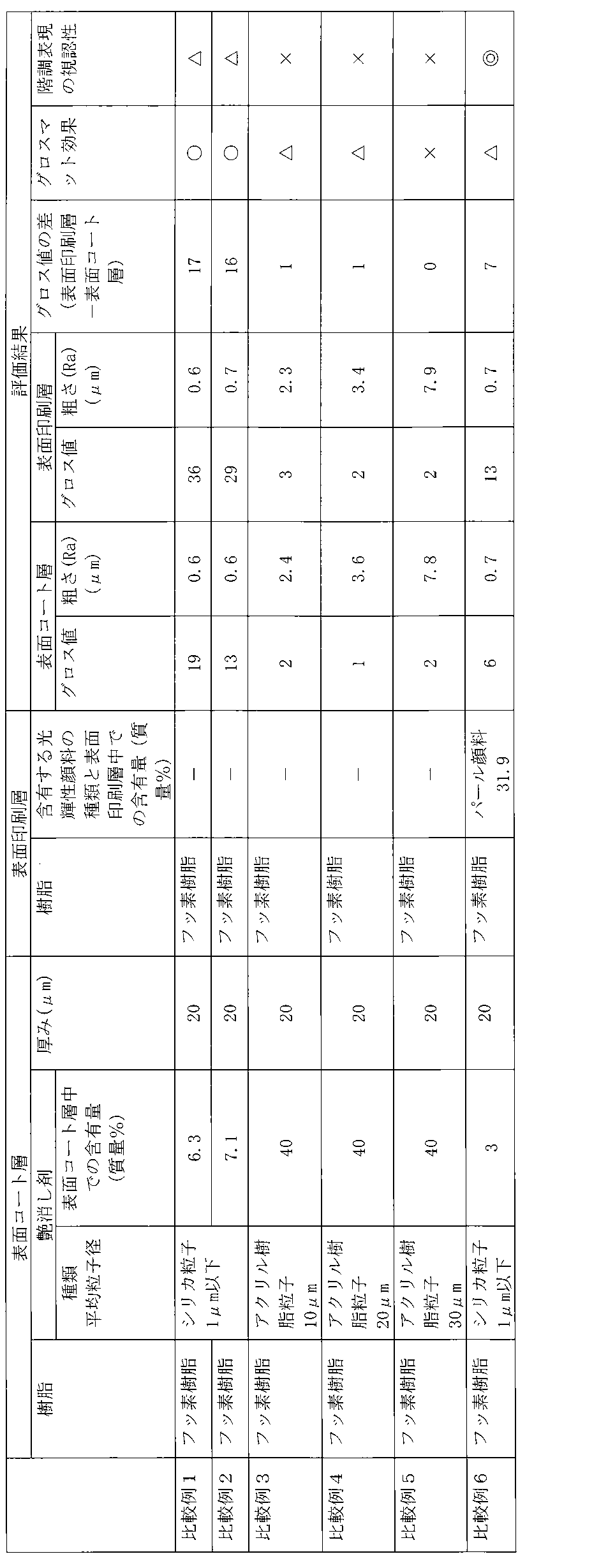
- Tables 1 to 3 show the evaluation results for each cosmetic material. From this result, when the surface coat layer is set to a thickness of 5 ⁇ m or more with a resin composition containing a fluororesin and a matting agent, the gloss value (incident light angle 60 °) of the surface coat layer is set to 10 or less. Further, by making the gloss value of the surface printing layer (incident light angle 60 °) 10 or more higher than the gloss value of the surface coat layer (incident light angle 60 °), the dot area ratio 20 together with the gloss matte effect. % Light gradation was sufficiently visible, the gradation expression effect was excellent, and it had a novel and good design (Examples 1 to 12). In addition, by including 3 to 23.8% by mass of a bright pigment in the surface print layer, the gradation expression effect can be significantly improved while maintaining an excellent gloss matte effect. It became clear (Examples 10 to 12).
Landscapes
- Chemical & Material Sciences (AREA)
- Engineering & Computer Science (AREA)
- Materials Engineering (AREA)
- Organic Chemistry (AREA)
- Chemical Kinetics & Catalysis (AREA)
- Mechanical Engineering (AREA)
- Metallurgy (AREA)
- Life Sciences & Earth Sciences (AREA)
- Wood Science & Technology (AREA)
- Physics & Mathematics (AREA)
- Plasma & Fusion (AREA)
- Laminated Bodies (AREA)
Abstract
Description
項1. 耐熱性基板に、少なくとも表面コート層と、部分的に設けられた表面印刷層とがこの順に積層されており、
前記表面コート層が、フッ素樹脂及び艶消し剤を含む樹脂組成物によって形成されており、その厚みが5μm以上であり、
前記表面コート層の表面のグロス値(入射光角60°)が10以下であり、且つ前記表面印刷層の表面のグロス値(入射光角60°)が前記表面コート層の表面のグロス値(入射光角60°)よりも10以上高い、
ことを特徴とする、化粧材。
項2. 前記表面印刷層の表面の中心線平均粗さが1.5μm以下である、項1に記載の化粧材。
項3. 前記表面印刷層が光輝性顔料を含む、項1又は2に記載の化粧材。
項4. 前記表面印刷層における光輝性顔料の含有量が1.5~30質量%である、項1~3のいずれかに記載の化粧材。
項5. 前記艶消し剤が無機粒子である、項1~4のいずれかに記載の化粧材。
項6. 前記艶消し剤の平均粒子径が5μm以下である、項1~5のいずれかに記載の化粧材。
項7. 前記表面印刷層の表面のグロス値(入射光角60°)が15以上である、項1~6のいずれかに記載の化粧材。
項8. 前記耐熱性基板と前記表面コート層との間に、着色又は透明のベースコート層が設けられている、項1~7のいずれかに記載の化粧材。
項9. 前記耐熱性基板と前記表面コート層との間に、絵柄層が設けられている、項1~8のいずれかに記載の化粧材。
項10. 前記ベースコート層と前記表面コート層との間に、絵柄層が設けられている、項9に記載の化粧材。
項11. 前記耐熱性基板と前記表面コート層との間に、前記耐熱性基板と接面するようにプライマー層が設けられている、項1~10のいずれかに記載の化粧材。
項12. 耐熱性基板上に、フッ素樹脂及び艶消し剤を含む樹脂組成物によって、厚みが5μm以上且つ表面のグロス値(入射光角60°)が10以下になるように表面コート層を形成する工程、
前記工程で形成した表面コート層の上に、表面のグロス値(入射光角60°)が当該表面コート層の表面のグロス値(入射光角60°)よりも10以上高い表面印刷層を部分的に形成する工程、
を含む、化粧材の製造方法。
本発明の化粧材は、図1に示すように、耐熱性基板1に、少なくとも表面コート層2と、部分的に設けられた表面印刷層3とがこの順に積層された積層構造を有する。
[耐熱性基板1]
耐熱性基板1は、本発明の化粧材において、支持部材としての役割を果たす。ここで、「耐熱性基板」とは、後述する表面コート層2と表面印刷層3を形成する際の焼き付けに耐え得る耐熱性を備えていることを指し、具体的には、230℃、好ましくは260℃の温度条件に5分間晒しても、熱変性(熱による劣化や変性)が生じない基板を指す。
表面コート層2は、耐熱性基板1上に設けられ、本発明の化粧材に耐候性を付与する役割を果たす。また、表面コート層2において、その上面に表面印刷層3(表面グロス領域)が設けられていない領域は、本発明の化粧材の最表層の一部を形成して表面マット領域になり、相対的に低い光沢を表出し、表面印刷層3と共に、グロスマット効果の発現に寄与する。更に、表面コート層2は、表面印刷層3による階調表現を可能にならしめる下地としての役割も果たす。
表面印刷層3は、表面コート層2の上に部分的に設けられ、本発明の化粧材の最表層の一部を形成して表面グロス領域になり、相対的に高い光沢を表出し、表面コート層2と共にグロスマット効果に寄与する。更に、表面印刷層3は、表面コート層2を下地として使用することにより、階調表現を表出する意匠効果を奏することができる。
プライマー層4は、耐熱性基板1と、その上部に配された各層との接着性を向上させるために、必要に応じて、耐熱性基板1と表面コート層2との間に設けられる層である。プライマー層4は、耐熱性基板1と接面させた状態で配置され、後述するベースコート層5を設ける場合には耐熱性基板1とベースコート層5の間に配置される。
ベースコート層5は、意匠性を高めるために、必要に応じて、耐熱性基板1と表面コート層2との間に設けられる層である。
絵柄層6は、絵柄を付与して意匠性を高めるために、必要に応じて、耐熱性基板1と表面コート層2との間に設けられる層である。絵柄層6は、ベースコート層5を設ける場合にはベースコート層5と表面コート層2との間に配置され、ベースコート層5を設けずにプライマー層4を設ける場合には、プライマー層4と表面コート層2との間に配置される。絵柄層6は、所定の層の上に、所望の絵柄を形成するように部分的に設けられる。
本発明の化粧材は、建築部材、建具、車両等の内装部材又は外装部材の表面化粧版として使用できるが、優れた耐候性を備えている点を鑑みれば、屋外又は準屋外に適用される外装部材として好適である。このような外装部材としては、具体的には、屋根、壁、床、ベランダの目隠し、(軒下)天井等の外装用建築部材の表面化粧板;扉、窓枠、手すり、周り縁、モール等の外装用建具の表面化粧板;自動車、電車等の車両の外装材等が挙げられる。
本発明の化粧材の製造方法については、前述する層構造と各層の組成を備え得ることを限度として特に制限されないが、好適な一例について、以下に説明する。
電気亜鉛めっき鋼板(厚み0.6mm)からなる耐熱性基板の上に、下記プライマー層用塗工液を焼付後の厚さが2μmとなるようにバーコート法にて塗布した後に、耐熱性基板の表面温度が224℃となる条件で1.5分間焼付を行い、耐熱性基板上の全面にプライマー層を形成した。
ポリエステル系プライマー塗料を、有機溶剤にて希釈して、これをプライマー層塗工液として使用した。
ポリエステル系プライマー塗料には、熱硬化性ポリエステル樹脂、硬化剤(メラミン)、防錆剤(リン酸亜鉛)が含まれており、固形分濃度が42質量%である。
フッ素系着色(グレー系色)塗料を、キシレン及びトルエンの混合溶剤(質量比1:1)にて希釈して、これをベースコート層用塗工液として使用した。
フッ素系着色(グレー系色)塗料には、熱硬化性フッ素樹脂、硬化剤(イソシアネート)、及びグレー系着色顔料(酸化チタン、酸化クロム)が含まれており、固形分濃度が40質量%であり、その内着色顔料分は10質量%である。
フッ素系クリア塗料と、表1~3に示す各艶消し剤とを、キシレン及びトルエンの混合溶剤(質量比1:1)にて希釈して、これを表面コート層用塗工液として使用した。
フッ素系クリア塗料には、熱硬化性フッ素樹脂、及び硬化剤(イソシアネート)が含まれており、固形分濃度が30質量%である。フッ素系クリア塗料には、着色剤は含まれていない。
フッ素系クリヤインキ、ポリエステル系クリヤインキ、又はアクリル系クリヤインキと、表1~3に示す各光輝性顔料とを、キシレン及びシクロヘキサノンの混合溶剤(質量比1:1)にて希釈して、これを表面印刷用インキとして使用した。
フッ素系クリヤインキには、熱硬化性フッ素樹脂、及び硬化剤(イソシアネート)が含まれており、固形分濃度が32質量%である。フッ素系クリヤインキには、着色剤は含まれていない。
ポリエステル系クリヤインキには、熱硬化性ポリエステル樹脂、及び硬化剤(メラミン)が含まれており、固形分濃度が41質量%である。ポリエステル系クリヤインキには、着色剤は含まれていない。
アクリル系クリヤインキには、熱硬化性アクリル樹脂、及び硬化剤(イソシアネート)が含まれており、固形分濃度が45質量%である。アクリル系クリヤインキには、着色剤は含まれていない。
前記で得られた各化粧材について、以下の方法に従って、グロス値、中心線平均粗さ、グロスマット効果、柄表現の視認性について評価した。
各化粧材における表面コート層が露出している領域と表面印刷層の領域のグロス値を、グロスメーター(「VG2000」、日本電色工業株式会社製)を使用し、入射角60℃の条件で測定した。
各化粧材における表面コート層が露出している領域と表面印刷層の領域について、表面粗さ測定器(「サーフコーダSE-40C(型番)」、株式会社小坂研究所製)を使用し、中心線平均粗さRa(μm)を測定した
各化粧材を目視にて観察し、以下の判定基準に従って、グロスマット効果を評価した。
(グロスマット効果の判定基準)
◎:表面コート層と表面印刷層との相対的な光沢差によるグロスマット効果が顕著に感じられる。
○:表面コート層と表面印刷層との相対的な光沢差によるグロスマット効果が感じられる。
△:表面コート層と表面印刷層との相対的な光沢差によるグロスマット効果が僅かに感じられる。
×:表面コート層と表面印刷層との相対的な光沢差によるグロスマット効果が殆ど感じられない。
各化粧材を目視にて観察し、以下の判定基準に従って、階調表現の視認性を評価した。
(階調表現の視認性の判定基準)
◎:網点面積率20%の淡い階調が非常に明瞭に現れている
○:網点面積率20%の淡い階調が前記◎の場合ほどではないが、十分に現れている。
△:網点面積率20%の淡い階調は僅かに現れ、網点面積率0%と20%との階調の差が僅かにだけ視認される。
×:網点面積率20%の淡い階調は殆ど現れておらず、網点面積率0%と20%との階調の差を視認できない。


2 表面コート層
3 表面印刷層
4 プライマー層
5 ベースコート層
6 絵柄層
Claims (12)
- 耐熱性基板に、少なくとも表面コート層と、部分的に設けられた表面印刷層とがこの順に積層されており、
前記表面コート層が、フッ素樹脂及び艶消し剤を含む樹脂組成物によって形成されており、その厚みが5μm以上であり、
前記表面コート層の表面のグロス値(入射光角60°)が10以下であり、且つ前記表面印刷層の表面のグロス値(入射光角60°)が前記表面コート層の表面のグロス値(入射光角60°)よりも10以上高い、
ことを特徴とする、化粧材。 - 前記表面印刷層の表面の中心線平均粗さが1.5μm以下である、請求項1に記載の化粧材。
- 前記表面印刷層が光輝性顔料を含む、請求項1又は2に記載の化粧材。
- 前記表面印刷層における光輝性顔料の含有量が1.5~30質量%である、請求項1~3のいずれかに記載の化粧材。
- 前記艶消し剤が無機粒子である、請求項1~4のいずれかに記載の化粧材。
- 前記艶消し剤の平均粒子径が5μm以下である、請求項1~5のいずれかに記載の化粧材。
- 前記表面印刷層の表面のグロス値(入射光角60°)が15以上である、請求項1~6のいずれかに記載の化粧材。
- 前記耐熱性基板と前記表面コート層との間に、着色又は透明のベースコート層が設けられている、請求項1~7のいずれかに記載の化粧材。
- 前記耐熱性基板と前記表面コート層との間に、絵柄層が設けられている、請求項1~8のいずれかに記載の化粧材。
- 前記ベースコート層と前記表面コート層との間に、絵柄層が設けられている、請求項8に記載の化粧材。
- 前記耐熱性基板と前記表面コート層との間に、前記耐熱性基板と接面するようにプライマー層が設けられている、請求項1~10のいずれかに記載の化粧材。
- 耐熱性基板上に、フッ素樹脂及び艶消し剤を含む樹脂組成物によって、厚みが5μm以上且つ表面のグロス値(入射光角60°)が10以下になるように表面コート層を形成する工程、
前記工程で形成した表面コート層の上に、表面のグロス値(入射光角60°)が当該表面コート層の表面のグロス値(入射光角60°)よりも10以上高い表面印刷層を部分的に形成する工程、
を含む、化粧材の製造方法。
Priority Applications (3)
| Application Number | Priority Date | Filing Date | Title |
|---|---|---|---|
| JP2017510072A JP6834944B2 (ja) | 2015-03-31 | 2016-03-30 | 外装用化粧材及びその製造方法 |
| US15/561,117 US10195830B2 (en) | 2015-03-31 | 2016-03-30 | Decorative panel for exterior use, and method for manufacturing same |
| EP16772917.7A EP3278983B1 (en) | 2015-03-31 | 2016-03-30 | Decorative panel for exterior use, and method for manufacturing same |
Applications Claiming Priority (2)
| Application Number | Priority Date | Filing Date | Title |
|---|---|---|---|
| JP2015073269 | 2015-03-31 | ||
| JP2015-073269 | 2015-03-31 |
Publications (1)
| Publication Number | Publication Date |
|---|---|
| WO2016159036A1 true WO2016159036A1 (ja) | 2016-10-06 |
Family
ID=57005066
Family Applications (1)
| Application Number | Title | Priority Date | Filing Date |
|---|---|---|---|
| PCT/JP2016/060292 Ceased WO2016159036A1 (ja) | 2015-03-31 | 2016-03-30 | 外装用化粧材及びその製造方法 |
Country Status (4)
| Country | Link |
|---|---|
| US (1) | US10195830B2 (ja) |
| EP (1) | EP3278983B1 (ja) |
| JP (1) | JP6834944B2 (ja) |
| WO (1) | WO2016159036A1 (ja) |
Cited By (7)
| Publication number | Priority date | Publication date | Assignee | Title |
|---|---|---|---|---|
| JP2018122576A (ja) * | 2017-02-03 | 2018-08-09 | 凸版印刷株式会社 | パールグロスマット化粧用シート |
| JP2018122577A (ja) * | 2017-02-03 | 2018-08-09 | 凸版印刷株式会社 | パールグロスマット化粧用シート |
| JP2018122575A (ja) * | 2017-02-03 | 2018-08-09 | 凸版印刷株式会社 | パール意匠化粧用シート |
| JP2018187855A (ja) * | 2017-05-09 | 2018-11-29 | バンドー化学株式会社 | グラデーションフィルム、加飾成形品及びグラデーションフィルムの製造方法 |
| KR20190029972A (ko) * | 2017-09-13 | 2019-03-21 | (주)엘지하우시스 | 이종 수지층이 구비된 적층 필름 및 이를 포함하는 바닥재 |
| JP2019056824A (ja) * | 2017-09-21 | 2019-04-11 | 株式会社タムラ製作所 | 感光性樹脂組成物の光硬化膜及び感光性樹脂組成物の光硬化膜を有するプリント配線板 |
| JPWO2025154638A1 (ja) * | 2024-01-18 | 2025-07-24 |
Families Citing this family (3)
| Publication number | Priority date | Publication date | Assignee | Title |
|---|---|---|---|---|
| JP2020179552A (ja) * | 2019-04-24 | 2020-11-05 | 凸版印刷株式会社 | プラスチックカード及びその製造方法 |
| WO2021153767A1 (ja) * | 2020-01-31 | 2021-08-05 | ケイミュー株式会社 | 建材、化粧部材及び化粧部材の製造方法 |
| CN117812859A (zh) * | 2021-11-12 | 2024-04-02 | Oppo广东移动通信有限公司 | 壳体、其制备方法及电子设备 |
Citations (5)
| Publication number | Priority date | Publication date | Assignee | Title |
|---|---|---|---|---|
| JP2008007709A (ja) * | 2006-06-30 | 2008-01-17 | Denki Kagaku Kogyo Kk | 内外装建材用表面保護フィルム及びその製造方法 |
| JP2008120031A (ja) * | 2006-11-15 | 2008-05-29 | Toppan Printing Co Ltd | 化粧シートおよびその製造方法 |
| JP2012210741A (ja) * | 2011-03-30 | 2012-11-01 | Dainippon Printing Co Ltd | 真空成形用化粧シート、及び該化粧シートを用いてなる化粧材 |
| JP2013018231A (ja) * | 2011-07-13 | 2013-01-31 | Dic Corp | 化粧シート及び化粧板 |
| JP2014184726A (ja) * | 2014-05-28 | 2014-10-02 | Dainippon Printing Co Ltd | 加飾シート、射出成形同時加飾方法、及び加飾成形品 |
Family Cites Families (6)
| Publication number | Priority date | Publication date | Assignee | Title |
|---|---|---|---|---|
| JPH10289633A (ja) * | 1997-04-15 | 1998-10-27 | Polymertech Kk | 加飾透光性キートップおよびその製造方法 |
| US20030205895A1 (en) * | 2001-03-27 | 2003-11-06 | Scarbrough Joel Scott | Reflective printed article and method of manufacturing same |
| JP4402339B2 (ja) * | 2002-08-30 | 2010-01-20 | 大日本印刷株式会社 | 化粧材 |
| JP4967429B2 (ja) | 2006-04-10 | 2012-07-04 | 大日本印刷株式会社 | 印刷物の製造方法 |
| CA2781785C (en) * | 2009-11-27 | 2018-07-17 | Basf Se | Coating compositions for security elements and holograms |
| KR20140004766A (ko) * | 2011-03-28 | 2014-01-13 | 후지필름 가부시키가이샤 | 발광소자용 반사기판 및 그 제조방법 |
-
2016
- 2016-03-30 EP EP16772917.7A patent/EP3278983B1/en active Active
- 2016-03-30 US US15/561,117 patent/US10195830B2/en active Active
- 2016-03-30 JP JP2017510072A patent/JP6834944B2/ja active Active
- 2016-03-30 WO PCT/JP2016/060292 patent/WO2016159036A1/ja not_active Ceased
Patent Citations (5)
| Publication number | Priority date | Publication date | Assignee | Title |
|---|---|---|---|---|
| JP2008007709A (ja) * | 2006-06-30 | 2008-01-17 | Denki Kagaku Kogyo Kk | 内外装建材用表面保護フィルム及びその製造方法 |
| JP2008120031A (ja) * | 2006-11-15 | 2008-05-29 | Toppan Printing Co Ltd | 化粧シートおよびその製造方法 |
| JP2012210741A (ja) * | 2011-03-30 | 2012-11-01 | Dainippon Printing Co Ltd | 真空成形用化粧シート、及び該化粧シートを用いてなる化粧材 |
| JP2013018231A (ja) * | 2011-07-13 | 2013-01-31 | Dic Corp | 化粧シート及び化粧板 |
| JP2014184726A (ja) * | 2014-05-28 | 2014-10-02 | Dainippon Printing Co Ltd | 加飾シート、射出成形同時加飾方法、及び加飾成形品 |
Non-Patent Citations (1)
| Title |
|---|
| See also references of EP3278983A4 * |
Cited By (9)
| Publication number | Priority date | Publication date | Assignee | Title |
|---|---|---|---|---|
| JP2018122576A (ja) * | 2017-02-03 | 2018-08-09 | 凸版印刷株式会社 | パールグロスマット化粧用シート |
| JP2018122577A (ja) * | 2017-02-03 | 2018-08-09 | 凸版印刷株式会社 | パールグロスマット化粧用シート |
| JP2018122575A (ja) * | 2017-02-03 | 2018-08-09 | 凸版印刷株式会社 | パール意匠化粧用シート |
| JP2018187855A (ja) * | 2017-05-09 | 2018-11-29 | バンドー化学株式会社 | グラデーションフィルム、加飾成形品及びグラデーションフィルムの製造方法 |
| KR20190029972A (ko) * | 2017-09-13 | 2019-03-21 | (주)엘지하우시스 | 이종 수지층이 구비된 적층 필름 및 이를 포함하는 바닥재 |
| KR102239674B1 (ko) | 2017-09-13 | 2021-04-13 | (주)엘지하우시스 | 이종 수지층이 구비된 적층 필름 및 이를 포함하는 바닥재 |
| JP2019056824A (ja) * | 2017-09-21 | 2019-04-11 | 株式会社タムラ製作所 | 感光性樹脂組成物の光硬化膜及び感光性樹脂組成物の光硬化膜を有するプリント配線板 |
| JPWO2025154638A1 (ja) * | 2024-01-18 | 2025-07-24 | ||
| JP7850500B2 (ja) | 2024-01-18 | 2026-04-23 | 株式会社ウェーブロック・アドバンスト・テクノロジー | 金属調加飾積層体、金属調物品及び加飾積層体の製造方法 |
Also Published As
| Publication number | Publication date |
|---|---|
| EP3278983A1 (en) | 2018-02-07 |
| US10195830B2 (en) | 2019-02-05 |
| JP6834944B2 (ja) | 2021-02-24 |
| JPWO2016159036A1 (ja) | 2018-02-01 |
| US20180126710A1 (en) | 2018-05-10 |
| EP3278983B1 (en) | 2020-05-06 |
| EP3278983A4 (en) | 2018-10-17 |
Similar Documents
| Publication | Publication Date | Title |
|---|---|---|
| WO2016159036A1 (ja) | 外装用化粧材及びその製造方法 | |
| JP6550916B2 (ja) | 化粧板及びその製造方法 | |
| US12420526B2 (en) | Decorative material, laminate, and method for manufacturing decorative material | |
| JP6746979B2 (ja) | 化粧板 | |
| JP7694460B2 (ja) | 化粧材、化粧材の製造方法、化粧材を用いた積層体 | |
| JP7736031B2 (ja) | 化粧材 | |
| JP4391224B2 (ja) | 凹凸模様を有する化粧材 | |
| JP2017159582A (ja) | 防湿化粧板および建材、化粧板、化粧シート | |
| JP6260408B2 (ja) | ちぢみ意匠化粧板 | |
| JP7600629B2 (ja) | 化粧板 | |
| JP2021091133A (ja) | 化粧板、化粧板の製造方法 | |
| JP4788452B2 (ja) | エンボス化粧板及びその製造方法 | |
| JP2006123373A (ja) | 化粧鋼板およびその製造方法 | |
| JP2025020743A (ja) | 化粧部材およびその製造方法 | |
| KR100621083B1 (ko) | 렌티큘라 시트를 구비한 강판 | |
| JP5274752B2 (ja) | 化粧板 | |
| JP2023151417A (ja) | 化粧板 | |
| JP2023177974A (ja) | プリント金属化粧板 | |
| JP2020146952A (ja) | 化粧材 | |
| JPH06320662A (ja) | 化粧板 |
Legal Events
| Date | Code | Title | Description |
|---|---|---|---|
| 121 | Ep: the epo has been informed by wipo that ep was designated in this application |
Ref document number: 16772917 Country of ref document: EP Kind code of ref document: A1 |
|
| ENP | Entry into the national phase |
Ref document number: 2017510072 Country of ref document: JP Kind code of ref document: A |
|
| WWE | Wipo information: entry into national phase |
Ref document number: 15561117 Country of ref document: US |
|
| NENP | Non-entry into the national phase |
Ref country code: DE |
|
| REEP | Request for entry into the european phase |
Ref document number: 2016772917 Country of ref document: EP |