WO2016159105A1 - シートサポート装置 - Google Patents
シートサポート装置 Download PDFInfo
- Publication number
- WO2016159105A1 WO2016159105A1 PCT/JP2016/060438 JP2016060438W WO2016159105A1 WO 2016159105 A1 WO2016159105 A1 WO 2016159105A1 JP 2016060438 W JP2016060438 W JP 2016060438W WO 2016159105 A1 WO2016159105 A1 WO 2016159105A1
- Authority
- WO
- WIPO (PCT)
- Prior art keywords
- base member
- seat
- cable
- support device
- seat support
- Prior art date
- Legal status (The legal status is an assumption and is not a legal conclusion. Google has not performed a legal analysis and makes no representation as to the accuracy of the status listed.)
- Ceased
Links
Images





Classifications
-
- B—PERFORMING OPERATIONS; TRANSPORTING
- B60—VEHICLES IN GENERAL
- B60N—SEATS SPECIALLY ADAPTED FOR VEHICLES; VEHICLE PASSENGER ACCOMMODATION NOT OTHERWISE PROVIDED FOR
- B60N2/00—Seats specially adapted for vehicles; Arrangement or mounting of seats in vehicles
- B60N2/90—Details or parts not otherwise provided for
- B60N2/914—Hydro-pneumatic adjustments of the shape
-
- A—HUMAN NECESSITIES
- A47—FURNITURE; DOMESTIC ARTICLES OR APPLIANCES; COFFEE MILLS; SPICE MILLS; SUCTION CLEANERS IN GENERAL
- A47C—CHAIRS; SOFAS; BEDS
- A47C7/00—Parts, details, or accessories of chairs or stools
- A47C7/36—Supports for the head or the back
- A47C7/40—Supports for the head or the back for the back
-
- B—PERFORMING OPERATIONS; TRANSPORTING
- B60—VEHICLES IN GENERAL
- B60N—SEATS SPECIALLY ADAPTED FOR VEHICLES; VEHICLE PASSENGER ACCOMMODATION NOT OTHERWISE PROVIDED FOR
- B60N2/00—Seats specially adapted for vehicles; Arrangement or mounting of seats in vehicles
- B60N2/02—Seats specially adapted for vehicles; Arrangement or mounting of seats in vehicles the seat or part thereof being movable, e.g. adjustable
- B60N2/22—Seats specially adapted for vehicles; Arrangement or mounting of seats in vehicles the seat or part thereof being movable, e.g. adjustable the back-rest being adjustable
- B60N2/2222—Seats specially adapted for vehicles; Arrangement or mounting of seats in vehicles the seat or part thereof being movable, e.g. adjustable the back-rest being adjustable the back-rest having two or more parts
-
- B—PERFORMING OPERATIONS; TRANSPORTING
- B60—VEHICLES IN GENERAL
- B60N—SEATS SPECIALLY ADAPTED FOR VEHICLES; VEHICLE PASSENGER ACCOMMODATION NOT OTHERWISE PROVIDED FOR
- B60N2/00—Seats specially adapted for vehicles; Arrangement or mounting of seats in vehicles
- B60N2/90—Details or parts not otherwise provided for
- B60N2/986—Side-rests
- B60N2/99—Side-rests adjustable
Definitions
- the present invention relates to a seat support device.
- a pneumatic seat support device that can change the support shape of a seat by deploying an airbag provided inside the seat and pressing a seat pad.
- a seat support device includes a movable member that moves by expansion and contraction of the airbag, a fixed member, and an elastic member that is interposed between the movable member and the fixed member.
- the seat support device described in Patent Document 1 includes a tension coil spring interposed between a movable member and a fixed member. When the airbag is contracted, the tension coil spring returns the movable member to the initial position based on the elastic force.
- the seat support device described in Patent Document 1 is provided with an elastic member when an external force in the direction in which the airbag is deployed acts on the movable member (for example, when an occupant pulls the movable member).
- the movable member can be operated indefinitely against the force. As a result, for example, there may be a problem that the restoring force of the elastic member becomes weak or the movable member comes off.
- An object of the present invention is to provide a more reliable seat support apparatus.
- a seat support device that solves the above problems is provided with a base member that is fixed to the inside of a seat, a paddle member that can be brought into contact with and separated from the base member, and the base member and the paddle member.
- An airbag that presses a seat pad of the seat through the paddle member in a state; and a cable member having a first end locked to the base member and a second end locked to the paddle member.
- FIG. 3 is a perspective view of a seat support device provided in the seat back side portion of FIG. 2. It is operation
- FIG. 7 in an airbag deployment state.
- FIG. 10 is a perspective view of the seat support device of FIG. 9 in an airbag deployment state.
- FIG. 10 is an enlarged view of the vicinity of a through hole formed in the upper end portion of the base member of FIG. 9. The enlarged view of the through-hole vicinity formed in the lower end part of the base member of FIG.
- a vehicle seat 1 includes a seat cushion 2, a seat back 3 tiltable with respect to a rear end portion of the seat cushion 2, and a headrest 4 provided at the upper end of the seat back 3. It is equipped with.
- a plurality of seat support devices 10 (10A, 10B) are provided inside the seat back 3.
- the seat back 3 includes seat back side portions 3a and 3b and a seat back shoulder portion 3c, each of which has a support shape that bulges forward. As a result, it is possible to ensure a good seating posture and maintain the seating posture of the occupant seated on the seat 1.
- Each seat support device 10 (10A, 10B) has an airbag 5 (5a to 5c) provided inside the seat back 3.
- Each air bag 5 expands and contracts by filling and discharging air performed by an air supply / exhaust device (not shown).
- the seat support device 10 (10A, 10B) can change the support shapes set in the seat back side portions 3a, 3b and the seat back shoulder portion 3c.
- the seat support device 10A disposed inside the seat back side portions 3a and 3b includes a base member 21 fixed to the frame 11 of the seat back 3, respectively. And a paddle member 22 provided so as to be able to contact and separate from the base member 21.
- the base member 21 has a surface Sa facing the paddle member 22 and a back surface Sb opposite to the surface Sa.
- the left and right seat support devices 10A arranged in the seat back side portions 3a and 3b have substantially the same configuration except for the left and right differences including the expansion / contraction operation of the airbag 5. Yes. Therefore, for convenience of explanation, only one seat back side portion 3a in the seat back 3 is shown in FIGS.
- the base member 21 has a substantially flat base member main body 21a and a plurality of ribs 23 provided on one surface (rib forming surface 21s) of the base member main body 21a.
- the base member 21 is fixed to the frame 11 of the seat back 3 with the back surface Sb of the base member 21 provided with the ribs 23 facing the back surface of the seat back 3 (upper side in FIGS. 2 and 3). .
- the paddle member 22 has a substantially flat outer shape and is disposed at a position facing the base member main body 21a. Note that flange-like folded portions 24 that protrude toward the base member main body 21a are formed at both side ends of the paddle member 22, respectively.
- the seat support device 10A holds the airbag 5 in such a manner that the airbag 5 (5a, 5b) is sandwiched between the paddle member 22 and the base member main body 21a.
- the paddle member 22 pressed against the airbag 5 is separated from the base member main body 21a disposed to face the paddle member 22.
- the paddle member 22 presses the seat pad 30 provided inside the seat back 3
- the portion where the seat pad 30 is pressed is displaced integrally with the skin 31 of the seat back 3.
- the seat pad 30 is formed using, for example, a sponge-like cushion material.
- the seat support device 10A swells the seat back side portions 3a and 3b to the front of the seat 1 (lower side in FIGS. 2 and 3), and forms the support shape of the seat back side portions 3a and 3b. change.
- the support surfaces 3s of the seat back side portions 3a and 3b abut against the occupant seated on the seat 1 from the outside in the seat width direction (right side in FIGS. 2 and 3). Further, the base member main body 21a and the paddle member 22 are disposed inside the seat back 3 in a manner that is substantially parallel to the support surface 3s.
- the seat pad 30 (30a, 30b) provided on the seat back side portions 3a, 3b is substantially in close contact with the paddle member 22 at a portion pressed against the paddle member 22 by the deployment of the airbag 5. .
- the support surfaces 3s of the seat back side portions 3a and 3b move to the front of the seat 1 and to the inside in the seat width direction (left side in FIGS. 2 and 3).
- the seat support apparatus 10A includes a cable member 40 that connects between the base member 21 and the paddle member 22.
- the cable member 40 has a first end 40 a locked to the base member 21 and a second end 40 b locked to the paddle member 22.
- the first end 40a of the cable member 40 is provided with a substantially spherical first terminal member 45a.
- the second end 40b of the cable member 40 is provided with a substantially cylindrical second terminal member 45b.
- the paddle member 22 is provided with a locking portion 46 having a slit-like insertion hole 46a.
- the second terminal member 45b is attached to the engaging portion 46 by being inserted into the insertion hole 46a along the slit shape. Thereby, the second end 40 b is locked to the paddle member 22.
- the cable member 40 is routed from the front surface side to the back surface side of the base member 21.
- the first end 40 a of the cable member 40 is locked to the base member 21 on the back surface side of the base member 21.
- the base member 21 includes a guide portion 48 provided at the upper end portion of the base member main body 21a.
- the guide portion 48 has a guide groove into which the cable member 40 is fitted, and is formed using a soft resin material having high slidability.
- the cable member 40 is routed along the rib forming surface 21s of the base member main body 21a in a manner extending downward from the upper end of the base member main body 21a along the guide portion 48.
- the seat support device 10A includes a compression coil spring 50 disposed on the back surface side of the base member 21 along the vertical direction of the base member main body 21a.
- the compression coil spring 50 is disposed below the guide portion 48 and between the two vertical ribs 23a and 23b provided in the rib forming surface 21s and extending in the vertical direction.
- a holding plate 51 is provided between the vertical ribs 23a and 23b, and a compression coil spring 50 is disposed between the holding plate 51 and the rib forming surface 21s.
- the cable member 40 is routed along the rib forming surface 21 s while being inserted into the compression coil spring 50.
- the cable member 40 has a substantially disk-shaped contact member (washer) 55 provided adjacent to the first terminal member 45a.
- the cable member 40 passes through the contact member 55 in the plate thickness direction.
- the horizontal rib 23c intersecting the two vertical ribs 23a and 23b located on both sides of the compression coil spring 50 in the vicinity of the upper end portion of the base member main body 21a. It is provided adjacent to the part 48.
- the compression coil spring 50 is held on the rib forming surface 21s in such a manner as to be sandwiched between the lateral rib 23c and the contact member 55.
- the cable member 40 is locked to the base member 21 on the back surface Sb of the base member 21 in a state where the contact member 55 provided at the first end 40 a receives the lower end of the compression coil spring 50. Has been. Thereby, the locking mechanism 61 of the cable member 40 is formed on the back surface Sb of the base member 21.
- the paddle member 22 is separated from the base member 21 by the deployment of the airbag 5, so that the contact member 55 as the first contact portion and the lateral rib 23 c as the second contact portion.
- the compression coil spring 50 sandwiched between the two is further compressed.
- a pulling mechanism 62 that pulls the first end 40 a of the cable member 40 based on the elastic force (elastic restoring force) of the compression coil spring 50 is formed on the back surface Sb of the base member 21.
- the pulling mechanism 62 returns the paddle member 22 separated from the base member 21 to the initial position (the position shown in FIG. 5), thereby expanding the airbag 5 (5a, 5b).
- the changed support shape of the seat back side portions 3a and 3b is quickly returned to the initial state.
- the operation of the paddle member 22 that is separated from the base member 21 when the compression coil spring 50 sandwiched between the contact member 55 and the lateral rib 23c reaches the compression limit.
- movement of the paddle member 22 and seat back side part 3a, 3b which comprises a movable part is restrict
- the seat support device 10B disposed inside the seat back shoulder portion 3c is also a seat support device disposed inside the seat back side portions 3a and 3b as described above.
- the same base member 71 and paddle member 72 as 10A are provided.
- the base member 71 in the seat support device 10B also includes a substantially flat base member main body 71a and a rib forming surface 71s of the base member main body 71a (the right side, the seat back 3 in FIGS. 7 and 8). And a plurality of ribs 23 provided on the back surface side of the head.
- the paddle member 72 has a flat plate-shaped portion 72 a that faces the base member main body 71 a and can be brought into contact with and separated from the base member 71.
- the seat support device 10 ⁇ / b> B is configured to hold the airbag 5 in such a manner that the airbag 5 (5 c) is sandwiched between the base member main body 71 a and the flat plate-shaped portion 72 a of the paddle member 72.
- the seat support device 10B is also configured such that when the airbag 5 is deployed, the paddle member 72 pressed against the airbag 5 is separated from the opposed base member main body 71a. As a result, the support shape of the seat back shoulder 3c bulging forward of the seat 1 is changed.
- the base member main body 71a and the flat plate-shaped portion 72a of the paddle member 72 are arranged inside the seat back 3 in a manner that is substantially parallel to the support surface 3s of the seat back shoulder portion 3c.
- the seat pad 30 (30 c) provided in the seat back shoulder portion 3 c is substantially in close contact with the paddle member 72 at a portion pressed against the paddle member 72 when the airbag 5 is deployed. As a result, the support surface 3s of the seat back shoulder 3c moves to the front of the seat 1.
- the seat support device 10B includes a plurality of cable members 80 that connect between the base member 71 and the paddle member 72.
- the seat support device 10B includes a first cable member 81 having a first end 80a locked to the upper end portion of the base member main body 71a, and a first cable member locked to the lower end portion of the base member main body 71a.
- a second cable member 82 having a first end 80a. The first cable member 81 and the second cable member 82 limit the operating range of the paddle member 72 that is separated from the base member 71 at two locations on the upper end side and the lower end side of the base member 71.
- each cable member 80 (81, 82) has a first end 80a and a second end 80b.
- a substantially spherical first terminal member 85a is provided at the first end 80a
- a substantially spherical second terminal member 85b is provided at the second end 80b.
- the second terminal member 85b is provided at two locations of the paddle member 72 facing the upper end portion and the lower end portion of the base member main body 71a, respectively, similarly to the locking portions 46 provided on the paddle member 22 of the seat support device 10A.
- the holding portions 86 and 87 for holding the second end 80b of each cable member 80 to the paddle member 22 are formed.
- the base member main body 71a is formed with through holes 88 and 89 that communicate the front surface Sa and the back surface Sb of the base member 71 at positions facing these locking portions 86 and 87, respectively.
- the first cable member 81 and the second cable member 82 are inserted through the through holes 88 and 89, respectively, so that the first end 80 a is disposed on the back surface side of the base member 71.
- the through-hole (groove) 88 has a slit shape that opens to the upper end of the base member main body 71a.
- the first cable member 81 is inserted into the through hole 88 from the upper end of the base member main body 71a.
- the through hole 89 formed in the lower end portion of the base member main body 71a has a shape in which the first terminal member 85a of the cable member 80 (82) can be inserted from the surface side of the base member 71. have.
- the through hole 89 has a substantially circular hole shape having a diameter larger than that of the first terminal member 85a.
- the through-hole 89 includes a groove-shaped recess 89a that extends downward. And the 2nd cable member 82 penetrated by the through-hole 89 is arrange
- the first terminal member 85 a of each cable member 80 is disposed on the back side of the base member 71.
- Each of the through holes 88 and 89 through which each cable member 80 is inserted has a hole shape such that the first terminal member 85 a cannot pass from the back surface side to the front surface side of the base member 71.
- the groove width of the through hole 88 provided in the upper end portion of the base member main body 71a is set to be narrower than the diameter of the first terminal member 85a of the first cable member 81. Yes.
- the groove width of the recessed part 89a of the through-hole 89 provided in the lower end part of the base member main body 71a is set narrower than the diameter of the 1st terminal member 85a of the 2nd cable member 82. Yes.
- these through holes 88 and 89 are formed in the process in which the first terminal member 85a of each cable member 80 moves from the back surface side to the front surface side of the base member 71. It is comprised so that it may contact
- the first terminal member 85a is used.
- the first end 80 a of each cable member 80 is drawn into the back surface side of the base member 71 due to the weight of.
- the cable members 80 are connected to the through holes 88 and 89.
- each cable member 80 It is pulled out to the surface side of the base member 71 via The first terminal member 85a of each cable member 80 comes into contact with and is engaged with the rib forming surface 71s of the base member main body 71a, so that each cable member 80 is fully extended. Accordingly, the operation of the paddle member 72 that is separated from the base member 71 is restricted, and the excessive operation of the paddle member 72 and the seat back shoulder portion 3c constituting the movable portion is restricted.
- each cable member 80 (81, 82) has mutually different tensile lengths L1, L2. That is, the first cable member 81 and the second cable member 82 are set to have different maximum lengths that are drawn to the surface side of the base member 71 when the paddle member 72 is separated from the base member 71. Specifically, in this embodiment, the tensile length L1 of the first cable member 81 is set to be longer than the tensile length L2 of the second cable member 82 (L1> L2). The first cable member 81 and the second cable member 82 regulate the operation of the paddle member 72 that is separated from the base member 71 to define the posture of the paddle member 72 when the airbag 5 (5c) is fully deployed.
- the upper portion of the paddle member 72 projects forward of the seat 1 rather than the lower portion of the paddle member 72, and the paddle member 72 is moved forward. It is configured to be tilted. As a result, the seat back shoulder portion 3c against which the seat pad 30 (30c) is pressed by the paddle member 72 is deformed into a support shape in which the upper side bulges forward of the seat 1 rather than the lower side.
- the seat support device 10 (10A, 10B) includes a base member (21, 71) fixed to the frame 11 of the seat back 3 and a paddle member that can contact and separate from the base member (21, 71). (22, 72). Further, the seat support device 10 holds the airbag 5 (5a to 5c) between the base member (21, 71) and the paddle member (22, 72).
- the seat support device 10 includes a first end (40a, 80a) locked to the base member (21, 71) and a second end (40b, 80b) locked to the paddle member (22, 72).
- the cable member (40, 80) which has is provided.
- the cable member (40, 80) connects the base member (21, 71) and the paddle member (22, 72), so that the paddle member (22, 22) separated from the base member (21, 71). , 72) can be limited.
- the seat support device 10 disposed inside the seat back 3 is desired to have a more compact configuration.
- the cable member (40, 80) has an advantage that a large arrangement space is not required regardless of the contact / separation state of the paddle member (22, 72) with respect to the base member (21, 71). Thereby, the seat support apparatus 10 can ensure high reliability with a compact and simple configuration.
- the cable member 40 is routed from the front surface side of the base member 21 facing the paddle member 22 to the back surface side of the base member 21. Is done. Further, the first end 40a of the cable member 40 is provided with an abutting member (washer) 55 as a first abutting portion, and the rear surface Sb of the base member 21, that is, the rib forming surface 21s of the base member main body 21a, A lateral rib 23c as a second contact portion is provided.
- the compression coil spring 50 as a compression spring member is held on the back side of the base member 21 in a compressed state by being sandwiched between the contact member 55 and the lateral rib 23c.
- the locking mechanism 61 that locks the first end 40a of the cable member 40 and the tension mechanism 62 that pulls the first end 40a of the cable member 40 on the back surface Sb of the base member 21 are compact. Can be formed. Thereby, the locking mechanism 61 and the pulling mechanism 62 can ensure high reliability with a compact and simple configuration.
- the paddle member 22 that is smoothly separated from the base member 21 is removed. It can be returned to the initial position. Further, the compression coil spring 50 sandwiched between the contact member 55 provided at the first end 40a of the cable member 40 and the lateral rib 23c of the base member 21 reaches the compression limit, so that it is separated from the base member 21. The operation of the paddle member 22 to be performed can be restricted. Further, by arranging the compression coil spring 50, the contact member 55, and the lateral rib 23c on the back surface side of the base member 21, the seat support device 10A can be made compact. Thereby, the arrangement
- the base member 21 includes a guide portion 48 provided at the upper end portion of the base member main body 21a.
- the cable member 40 is guided from the front surface side of the base member 21 to the back surface side of the base member 21 by being guided by the guide portion 48.
- the movement of the cable member 40 drawn from the front surface side to the back surface side of the base member 21 can be smoothed. Thereby, high reliability can be ensured by reducing the wear of the cable member 40 or the possibility of the cable member 40 becoming tangled.
- the design freedom of the locking mechanism 61 and the tension mechanism 62 formed on the back surface Sb of the base member 21 can be increased.
- through holes 88 and 89 are formed in the base member 71 (specifically, the base member main body 71a).
- the first end 80 a of the first cable member 81 is inserted through the through hole 88, and the first end 80 a of the second cable member 82 is inserted through the through hole 89.
- a first end member 85 a that cannot pass through the through holes 88 and 89 from the back surface side to the front surface side of the base member 71 is provided at the first end 80 a of each cable member 80.
- the first terminal member 85a is locked to the back surface Sb of the base member 71 when the cable members 80 are in the fully extended state. Accordingly, the operation of the paddle member 72 that is separated from the base member 71 can be more reliably regulated with a compact and simple configuration. Further, when the base member 71 and the paddle member 72 are close to each other, each cable member 80 is pulled into the back surface side of the base member 71 due to the weight of the first terminal member 85a. Thereby, possibility that each cable member 80 will be entangled can be reduced. As a result, higher reliability can be ensured.
- the seat support device 10B includes a first cable member 81 having a first end 80a locked to the upper end portion of the base member main body 71a, and a first end 80a locked to the lower end portion of the base member main body 71a.
- a second cable member 82 having The tensile length L1 of the first cable member 81 is longer than the tensile length L2 of the second cable member 82 (L1> L2).
- the paddle member 72 when the airbag 5 is deployed, the paddle member 72 can be in a forward inclined posture in which the upper portion protrudes toward the front side of the seat 1 than the lower portion.
- the seat support device 10A having the compression coil spring 50 is provided inside the seat back side portions 3a and 3b, and such a compression coil spring 50 is not provided inside the seat back shoulder portion 3c.
- a seat support device 10B is provided.
- the present invention is not limited thereto, and the seat support device 10B that does not have the compression coil spring 50 is provided inside the seat back side portions 3a and 3b, and the seat support device 10A that has the compression coil spring 50 is provided inside the seat back shoulder portion 3c. It may be provided. Then, either the seat support device 10A or the seat support device 10B may be provided in the seat back side portions 3a and 3b and the seat back shoulder portion 3c.
- the seat support device 10B that does not have the compression coil spring 50 also uses the first terminal member 85a provided at the first end 80a of the cable member 80 as a weight, so that the seat support device 10A using the compression coil spring 50 is used. A tensile force equivalent to that of the tension mechanism 62 can be applied.
- the seat support device 10 (10A, 10B) is disposed inside the seat back side portions 3a, 3b and inside the seat back shoulder portion 3c.
- the present invention is not limited to this, and the arrangement of the seat support device 10 may be arbitrarily set.
- the seat support device 10 may be disposed inside the seat cushion 2 or the headrest 4.
- the seat support device 10 may be disposed at a place other than the seat back side portions 3a and 3b and the seat back shoulder portion 3c in the seat back 3.
- the seat support device 10 may be arranged in an additional component of the seat such as an ottoman. The total number and arrangement of the seat support devices 10 may be arbitrarily changed.
- the compression coil spring 50 as the compression spring member, and the first contact portion (contact member 55) and the second contact portion (the contact member 55) that sandwich the compression coil spring 50 in the vertical direction
- the locking mechanism 61 and the pulling mechanism 62 are formed by the lateral ribs 23c).
- the configuration of the locking mechanism 61 and the pulling mechanism 62 may be arbitrarily changed as long as it is provided on the back side of the base member 21 without being limited thereto.
- the arrangement of the compression coil spring 50 and the second contact portion may be arbitrarily changed. Further, a compression spring member other than the compression coil spring 50 may be sandwiched between the first contact portion and the second contact portion. A plurality of compression spring members may be used. Further, the locking mechanism 61 and the pulling mechanism 62 may be independent. The tension mechanism 62 may use a tension spring member or other urging member.
- the cable member 40 is routed from the front surface side to the back surface side of the base member 21 via the guide portion 48 provided at the upper end portion of the base member main body 21a.
- the present invention is not limited to this, and the cable member 40 may be routed from the front surface side to the back surface side of the base member 21 via other parts such as the lower end portion of the base member main body 21a or a through hole.
- the guide portion 48 does not have to be provided at a location where the cable member 40 is routed.
- the cable members 80 (81, 82) are inserted through the through holes 88 and 89 formed in the base member main body 71a.
- the first terminal member 85 a is locked to the base member 71 by contacting the base member main body 71 a from the back side of the base member 71.
- the present invention is not limited thereto, and the locking structure of the first end 80a of each cable member 80 with respect to the base member 71 may be arbitrarily changed.
- the configuration may be such that each cable member 80 is loosened on the front side or the back side of the base member 71.
- the seat support device 10B includes two cable members 80 (81, 82) having different tensile lengths (L1, L2).
- the present invention is not limited to this, and the seat support device 10B may include three or more cable members 80 having different tensile lengths. Thereby, the attitude
- the seat support device 10B may include a plurality of cable members 80 having the same tensile length. All the cable members 80 may have the same tensile length.
Landscapes
- Engineering & Computer Science (AREA)
- Aviation & Aerospace Engineering (AREA)
- Transportation (AREA)
- Mechanical Engineering (AREA)
- Seats For Vehicles (AREA)
- Chair Legs, Seat Parts, And Backrests (AREA)
- Air Bags (AREA)
Abstract
シートサポート装置は、シートの内側に固定されるベース部材と、前記ベース部材に対して接離可能なパドル部材と、前記ベース部材と前記パドル部材との間に設けられ、展開状態において前記パドル部材を介して前記シートのシートパッドを押圧するエアバッグと、前記ベース部材に係止される第1端及び前記パドル部材に係止される第2端を有するケーブル部材と、を備える。
Description
本発明は、シートサポート装置に関するものである。
シートの内側に設けられたエアバッグが展開してシートパッドを押圧することにより、シートのサポート形状を変更することが可能な空気圧式のシートサポート装置がある。また、多くの場合、このようなシートサポート装置は、そのエアバッグの拡縮により移動する可動部材と、固定部材と、可動部材と固定部材との間に介在された弾性部材と、を備える。例えば、特許文献1に記載のシートサポート装置は、可動部材と固定部材との間に介在された引張コイルバネを備える。そして、エアバッグの収縮時には、引張コイルバネは、その弾性力に基づいて、可動部材を初期位置に復帰させる。
しかしながら、特許文献1に記載のシートサポート装置は、可動部材に対し、エアバッグが展開する方向の外力が作用した場合(例えば、乗員が可動部材を引っ張った場合等)には、弾性部材の付勢力に抗して、際限なく、その可動部材を動作させることが可能になっている。そして、これにより、例えば、その弾性部材の復元力が弱くなる、或いは可動部材が外れてしまう等といった問題が生ずるおそれがある。
本発明の目的は、より信頼性の高いシートサポート装置を提供することにある。
上記課題を解決するシートサポート装置は、シートの内側に固定されるベース部材と、前記ベース部材に対して接離可能なパドル部材と、前記ベース部材と前記パドル部材との間に設けられ、展開状態において前記パドル部材を介して前記シートのシートパッドを押圧するエアバッグと、前記ベース部材に係止される第1端及び前記パドル部材に係止される第2端を有するケーブル部材と、を備える。
以下、シートサポート装置の一実施形態を図面に従って説明する。
図1に示すように、車両用のシート1は、シートクッション2と、このシートクッション2の後端部に対して傾動自在なシートバック3と、シートバック3の上端に設けられたヘッドレスト4と、を備えている。そして、そのシートバック3の内部には、複数のシートサポート装置10(10A,10B)が設けられている。
図1に示すように、車両用のシート1は、シートクッション2と、このシートクッション2の後端部に対して傾動自在なシートバック3と、シートバック3の上端に設けられたヘッドレスト4と、を備えている。そして、そのシートバック3の内部には、複数のシートサポート装置10(10A,10B)が設けられている。
また、シートバック3は、シートバックサイド部3a,3b及びシートバックショルダ部3cを有し、これらは、それぞれ、前方に向かって膨出したサポート形状を有している。そして、これにより、そのシート1に着座した乗員の良好な着座姿勢を確保し且つその着座姿勢を維持することが可能になっている。
各シートサポート装置10(10A,10B)は、シートバック3の内側に設けられたエアバッグ5(5a~5c)を有している。各エアバッグ5は、図示しない給排気装置が行う空気の充填及び排出により拡縮する。そして、これにより、シートサポート装置10(10A,10B)は、シートバックサイド部3a,3b及びシートバックショルダ部3cに設定されたサポート形状を変更することが可能である。
詳述すると、図2~図4に示すように、シートバックサイド部3a,3bの内側に配置されたシートサポート装置10Aは、それぞれ、シートバック3のフレーム11に固定されるベース部材21と、このベース部材21に対して接離可能に設けられたパドル部材22と、を備えている。ベース部材21は、パドル部材22に対向する表面Saと、表面Saの反対側の裏面Sbとを有する。
尚、本実施形態では、シートバックサイド部3a,3bに配置される左右のシートサポート装置10Aは、エアバッグ5の拡縮動作を含め、その左右の違いを除いて略同一の構成を有している。このため、説明の便宜上、図2及び図3には、シートバック3における一方のシートバックサイド部3aのみを記載する。
ベース部材21は、略平板状のベース部材本体21aと、該ベース部材本体21aの片面(リブ形成面21s)に設けられた複数のリブ23と、を有している。そして、リブ23が設けられたベース部材21の裏面Sbをシートバック3の背面(図2及び図3中、上側)に向けた状態で、ベース部材21がシートバック3のフレーム11に固定される。
また、パドル部材22は、略平板状の外形を有して、ベース部材本体21aに対向する位置に配置されている。尚、このパドル部材22の両側端部には、それぞれ、ベース部材本体21aに向かって突出するフランジ状の折り返し部24が形成されている。そして、シートサポート装置10Aは、このパドル部材22とベース部材本体21aとの間にエアバッグ5(5a,5b)挟み込む態様で、エアバッグ5を保持する。
エアバッグ5が展開することにより、当該エアバッグ5に押圧されたパドル部材22が、その対向配置されたベース部材本体21aから離間する。これにより、シートバック3の内側に設けられたシートパッド30をパドル部材22が押圧することで、そのシートパッド30が押圧される部位がシートバック3の表皮31と一体に変位することになる。尚、シートパッド30は、例えば、スポンジ状のクッション素材等を用いて形成されている。このように、シートサポート装置10Aは、シートバックサイド部3a,3bをシート1の前方(図2及び図3中、下側)に膨出させて、シートバックサイド部3a,3bのサポート形状を変更する。
シートバックサイド部3a,3bのサポート面3sは、シート1に着座した乗員に対し、シート幅方向外側(図2及び図3中、右側)から当接する。また、このサポート面3sに対してベース部材本体21a及びパドル部材22が略並行する態様でシートバック3の内側に配置されている。尚、そのシートバックサイド部3a,3bに設けられたシートパッド30(30a,30b)は、エアバッグ5の展開によりパドル部材22に押圧される部分が、当該パドル部材22に対して略密着する。これにより、そのシートバックサイド部3a,3bのサポート面3sがシート1の前方及びシート幅方向内側(図2及び図3中、左側)に移動する。
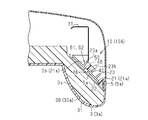
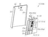
また、図4~図6に示すように、シートサポート装置10Aは、ベース部材21とパドル部材22との間を接続するケーブル部材40を備えている。具体的には、このケーブル部材40は、ベース部材21に係止される第1端40aと、パドル部材22に係止される第2端40bと、を有する。そして、これにより、ベース部材21から離間するパドル部材22の動作範囲、即ちエアバッグ5が展開する方向におけるパドル部材22の動作範囲が制限されている。
詳述すると、ケーブル部材40の第1端40aには、略球状の第1端末部材45aが設けられている。また、ケーブル部材40の第2端40bには、略円柱状の第2端末部材45bが設けられている。パドル部材22には、スリット状の挿通孔46aを有した係止部46が設けられている。第2端末部材45bは、この係止部46に対し、そのスリット形状に沿って挿通孔46aに挿通されて取着される。これにより、第2端40bがパドル部材22に係止される。
また、ケーブル部材40は、ベース部材21の表面側から裏面側に引き回されている。ケーブル部材40の第1端40aは、ベース部材21の裏面側において、当該ベース部材21に対して係止される。
ベース部材21は、そのベース部材本体21aの上端部分に設けられたガイド部48を備えている。このガイド部48は、ケーブル部材40が嵌合する案内溝を有するとともに、摺動性の高い軟質の樹脂素材を用いて形成されている。ケーブル部材40は、このガイド部48に沿ってベース部材本体21aの上端から下方に延びる態様で、ベース部材本体21aのリブ形成面21sに沿って配索される。
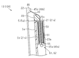
また、シートサポート装置10Aは、ベース部材本体21aの上下方向に沿うように、ベース部材21の裏面側に配置された圧縮コイルバネ50を備えている。具体的には、圧縮コイルバネ50は、上記ガイド部48の下方において、リブ形成面21sに設けられた上下方向に延びる二本の縦リブ23a,23b間に配置されている。これらの縦リブ23a,23b間には押え板51が設けられ、該押え板51とリブ形成面21sとの間に圧縮コイルバネ50が配置されている。ケーブル部材40は、この圧縮コイルバネ50内に挿通された状態で、リブ形成面21sに沿って配索されている。
ケーブル部材40は、第1端末部材45aに隣接して設けられた略円板状の当接部材(ワッシャ)55を有している。この当接部材55をその板厚方向にケーブル部材40が貫通する。また、ベース部材本体21aのリブ形成面21sには、ベース部材本体21aの上端部近傍において、圧縮コイルバネ50の両側に位置する二本の縦リブ23a,23bに交差する横リブ23cが、上記ガイド部48に隣接して設けられている。圧縮コイルバネ50は、横リブ23cと当接部材55との間に挟み込まれる態様で、リブ形成面21sに保持されている。
図5に示すように、ケーブル部材40は、その第1端40aに設けられた当接部材55が圧縮コイルバネ50の下端を受け止める状態で、ベース部材21の裏面Sbにおいて該ベース部材21に係止されている。これにより、ベース部材21の裏面Sbにケーブル部材40の係止機構61が形成されている。
また、図6に示すように、エアバッグ5の展開によりパドル部材22がベース部材21から離間することで、第1当接部としての当接部材55と第2当接部としての横リブ23cとの間に挟み込まれた圧縮コイルバネ50は、更に圧縮されることになる。
即ち、ベース部材21の裏面Sbには、圧縮コイルバネ50の弾性力(弾性復元力)に基づいてケーブル部材40の第1端40aを引張する引張機構62が形成されている。引張機構62は、エアバッグ5の収縮時、ベース部材21から離間したパドル部材22を初期位置(図5に示された位置)に復帰させることで、エアバッグ5(5a,5b)の展開により変更されたシートバックサイド部3a,3bのサポート形状を速やかに初期状態まで復帰させる。
更に、本実施形態のシートサポート装置10Aは、当接部材55と横リブ23cとの間に挟み込まれた圧縮コイルバネ50が圧縮限界に到達することにより、ベース部材21から離間するパドル部材22の動作を規制する。これにより、可動部を構成するパドル部材22及びシートバックサイド部3a,3bの過大な動作が制限される。
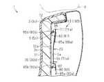
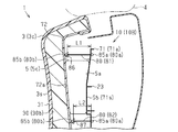
また、図7及び図8に示すように、シートバックショルダ部3cの内側に配置されたシートサポート装置10Bもまた、上記のようなシートバックサイド部3a,3bの内側に配置されたシートサポート装置10Aと同様のベース部材71及びパドル部材72を備えている。具体的には、このシートサポート装置10Bにおけるベース部材71もまた、略平板状のベース部材本体71aと、該ベース部材本体71aのリブ形成面71s(図7及び図8中、右側、シートバック3の背面側)に設けられた複数のリブ23と、を備えている。パドル部材72は、ベース部材本体71aに対向する平板形状部72aを有してベース部材71と接離可能である。シートサポート装置10Bは、これらベース部材本体71aとパドル部材72の平板形状部72aとの間にエアバッグ5(5c)を挟み込む態様で、そのエアバッグ5を保持する構成になっている。
即ち、シートサポート装置10Bもまた、エアバッグ5が展開することにより、当該エアバッグ5に押圧されたパドル部材72が、その対向配置されたベース部材本体71aから離間する構成になっている。これにより、シート1の前方に膨出したシートバックショルダ部3cのサポート形状が変更される。
シートバックショルダ部3cのサポート面3sに対し、ベース部材本体71a及びパドル部材72の平板形状部72aが略並行する態様で、シートバック3の内側に配置されている。シートバックショルダ部3cに設けられたシートパッド30(30c)は、エアバッグ5の展開によりパドル部材72に押圧される部分が、当該パドル部材72に対して略密着する。これにより、そのシートバックショルダ部3cのサポート面3sがシート1の前方に移動する。
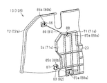
また、シートサポート装置10Bは、ベース部材71とパドル部材72との間を接続する複数のケーブル部材80を備えている。具体的には、このシートサポート装置10Bは、ベース部材本体71aの上端部分に係止される第1端80aを有する第1ケーブル部材81と、ベース部材本体71aの下端部分に係止される第1端80aを有する第2ケーブル部材82と、を備えている。第1ケーブル部材81と第2ケーブル部材82とは、ベース部材71の上端側及び下端側の二箇所において、当該ベース部材71から離間するパドル部材72の動作範囲を制限する。
詳述すると、図7~図10に示すように、各ケーブル部材80(81,82)は、第1端80a及び第2端80bを有する。第1端80aには略球状の第1端末部材85aが設けられ、第2端80bには略球状の第2端末部材85bが設けられる。また、ベース部材本体71aの上端部分及び下端部分に対向するパドル部材72の二箇所に、それぞれ、上記シートサポート装置10Aのパドル部材22に設けられた係止部46と同様、第2端末部材85bを保持することによって各ケーブル部材80の第2端80bをパドル部材22に係止する係止部86,87が形成されている。ベース部材本体71aには、これらの係止部86,87に対向する位置に、それぞれ、ベース部材71の表面Saと裏面Sbとを連通する貫通孔88,89が形成されている。そして、第1ケーブル部材81と第2ケーブル部材82がこれらの貫通孔88,89にそれぞれ挿通されることにより、その第1端80aがベース部材71の裏面側に配置されている。
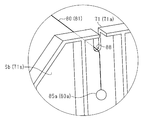
具体的には、図11に示すように、貫通孔(溝)88は、そのベース部材本体71aの上端に開口するスリット形状を有している。第1ケーブル部材81は、この貫通孔88に対し、ベース部材本体71aの上端から入れられる。
また、図12に示すように、ベース部材本体71aの下端部に形成された貫通孔89は、ベース部材71の表面側から、ケーブル部材80(82)の第1端末部材85aを挿入可能な形状を有している。この貫通孔89は、第1端末部材85aよりも直径の大きな略円孔形状を有している。この貫通孔89は下方に延びる溝状の凹部89aを含む。そして、貫通孔89に挿通された第2ケーブル部材82は、第1端末部材85aの重みによって、この凹部89a内に配置される。
各ケーブル部材80の第1端末部材85aが、ベース部材71の裏面側に配置される。各ケーブル部材80が挿通される各貫通孔88,89は、第1端末部材85aがベース部材71の裏面側から表面側に通過できないような孔形状を有している。
具体的には、図11に示すように、ベース部材本体71aの上端部に設けられた貫通孔88の溝幅は、第1ケーブル部材81の第1端末部材85aの直径よりも狭く設定されている。そして、図12に示すように、ベース部材本体71aの下端部に設けられた貫通孔89の凹部89aの溝幅は、第2ケーブル部材82の第1端末部材85aの直径よりも狭く設定されている。
つまり、これらの貫通孔88,89は、各ケーブル部材80の第1端末部材85aがベース部材71の裏面側から表面側に移動する過程で、第1端末部材85aがベース部材本体71aのリブ形成面71sに当接するように構成されている。これにより、各ケーブル部材80の第1端80aが、ベース部材71の裏面Sbにおいて当該ベース部材71に係止される。
具体的には、図7及び図9に示すように、エアバッグ5の収縮によりベース部材本体71aとパドル部材72の平板形状部72aとが近接した状態にある場合には、第1端末部材85aの重みによって、各ケーブル部材80の第1端80aがベース部材71の裏面側に引き込まれている。また、図8及び図10に示すように、エアバッグ5の展開によりパドル部材72の平板形状部72aがベース部材本体71aから離間する場合には、各ケーブル部材80が、各貫通孔88,89を介してベース部材71の表面側に引き出される。各ケーブル部材80の第1端末部材85aがベース部材本体71aのリブ形成面71sに当接して係止されることにより、各ケーブル部材80が伸びきった状態となる。これにより、ベース部材71から離間するパドル部材72の動作が規制され、可動部を構成するパドル部材72及びシートバックショルダ部3cの過大な動作が制限される。
また、図8に示すように、各ケーブル部材80(81,82)が、互いに異なる引張長さL1,L2を有している。即ち、第1ケーブル部材81及び第2ケーブル部材82は、パドル部材72がベース部材71から離間する時、ベース部材71の表面側に引き出される最大の長さが互いに異なる値に設定されている。具体的には、本実施形態では、第1ケーブル部材81の引張長さL1の方が、第2ケーブル部材82の引張長さL2よりも長く設定されている(L1>L2)。これら第1ケーブル部材81及び第2ケーブル部材82は、ベース部材71から離間するパドル部材72の動作を規制して、エアバッグ5(5c)の最大展開時におけるパドル部材72の姿勢を規定する。
即ち、本実施形態のシートサポート装置10Bは、エアバッグ5の展開時、パドル部材72の下側部分よりもパドル部材72の上側部分の方がシート1の前方に突出して、パドル部材72が前傾姿勢となるように構成されている。これにより、そのパドル部材72によってシートパッド30(30c)が押圧されるシートバックショルダ部3cは、その上側の方が下側よりもシート1の前方に膨出したサポート形状に変形する。
以上、本実施形態によれば、以下のような効果を得ることができる。
(1)シートサポート装置10(10A,10B)は、シートバック3のフレーム11に固定されるベース部材(21,71)と、このベース部材(21,71)に対して接離可能なパドル部材(22,72)と、を備える。また、シートサポート装置10は、これらベース部材(21,71)とパドル部材(22,72)との間にエアバッグ5(5a~5c)を保持する。そして、シートサポート装置10は、ベース部材(21,71)に係止される第1端(40a,80a)及びパドル部材(22,72)に係止される第2端(40b,80b)を有するケーブル部材(40,80)を備える。
(1)シートサポート装置10(10A,10B)は、シートバック3のフレーム11に固定されるベース部材(21,71)と、このベース部材(21,71)に対して接離可能なパドル部材(22,72)と、を備える。また、シートサポート装置10は、これらベース部材(21,71)とパドル部材(22,72)との間にエアバッグ5(5a~5c)を保持する。そして、シートサポート装置10は、ベース部材(21,71)に係止される第1端(40a,80a)及びパドル部材(22,72)に係止される第2端(40b,80b)を有するケーブル部材(40,80)を備える。
上記構成によれば、ベース部材(21,71)とパドル部材(22,72)とをケーブル部材(40,80)が接続することで、ベース部材(21,71)から離間するパドル部材(22,72)の動作範囲を制限することができる。また、シートバック3の内側に配置されるシートサポート装置10には、よりコンパクトな構成であることが望まれる。この点においても、ケーブル部材(40,80)には、ベース部材(21,71)に対するパドル部材(22,72)の接離状態に依らず、大きな配置スペースを必要としないという利点がある。これにより、シートサポート装置10は、コンパクト、且つ簡素な構成にて、高い信頼性を確保することができる。
(2)シートバックサイド部3a,3bの内側に配置されたシートサポート装置10Aでは、ケーブル部材40は、パドル部材22に対向するベース部材21の表面側から当該ベース部材21の裏面側に引き回される。また、ケーブル部材40の第1端40aには、第1当接部としての当接部材(ワッシャ)55が設けられ、ベース部材21の裏面Sbすなわちベース部材本体21aのリブ形成面21sには、第2当接部としての横リブ23cが設けられる。そして、圧縮バネ部材としての圧縮コイルバネ50は、当接部材55と横リブ23cとの間に挟み込まれることにより圧縮された状態で、ベース部材21の裏面側で保持される。
上記構成によれば、ベース部材21の裏面Sbにおいて、ケーブル部材40の第1端40aを係止する係止機構61、及び当該ケーブル部材40の第1端40aを引張する引張機構62をコンパクトに形成することができる。これにより、係止機構61及び引張機構62は、コンパクト、且つ簡素な構成にて、高い信頼性を確保することができる。
即ち、圧縮コイルバネ50の弾性力(弾性復元力)に基づきケーブル部材40の第1端40aを引張することで、エアバッグ5の収縮時、円滑に、そのベース部材21から離間したパドル部材22を初期位置に復帰させることができる。また、ケーブル部材40の第1端40aに設けられた当接部材55とベース部材21の横リブ23cとの間に挟み込まれた圧縮コイルバネ50が圧縮限界に到達することで、ベース部材21から離間するパドル部材22の動作を規制することができる。更に、その圧縮コイルバネ50、当接部材55、及び横リブ23cをベース部材21の裏面側に配置することで、シートサポート装置10Aのコンパクト化を図ることができる。これにより、シートサポート装置10Aの配置自由度が向上することで、そのシートバック3内側のスペースを有効に利用することができる。
(3)ベース部材21は、ベース部材本体21aの上端部分に設けられたガイド部48を備える。そして、ケーブル部材40は、このガイド部48に案内されることによりベース部材21の表面側から当該ベース部材21の裏面側に引き回される。
上記構成によれば、パドル部材22がベース部材21から離間することにより当該ベース部材21の裏面側から表面側に引き出されるケーブル部材40の動きと、パドル部材22がベース部材21に接近することにより当該ベース部材21の表面側から裏面側に引き込まれるケーブル部材40の動きと、を円滑化することができる。これにより、ケーブル部材40の摩耗、或いは当該ケーブル部材40が絡まる可能性を低減することで、高い信頼性を確保することができる。加えて、そのベース部材21の裏面Sbに形成される係止機構61及び引張機構62の設計自由度を高めることができる。
(4)シートバックショルダ部3cの内側に配置されたシートサポート装置10Bにおいて、ベース部材71(具体的には、ベース部材本体71a)には貫通孔88,89が形成される。第1ケーブル部材81の第1端80aが貫通孔88に挿通され、第2ケーブル部材82の第1端80aが貫通孔89に挿通される。各ケーブル部材80の第1端80aには、それぞれ、これらの貫通孔88,89をベース部材71の裏面側から表面側に通過できない第1端末部材85aが設けられる。
上記構成によれば、各ケーブル部材80が伸びきった状態となることで、第1端末部材85aが、ベース部材71の裏面Sbに係止される。これにより、コンパクト、且つ簡素な構成にて、より確実に、ベース部材71から離間するパドル部材72の動作を規制することができる。また、ベース部材71とパドル部材72とが近接した状態にある場合には、第1端末部材85aの重みによって、各ケーブル部材80がベース部材71の裏面側に引き込まれた状態となる。これにより、各ケーブル部材80が絡まる可能性を低減することができる。その結果、より高い信頼性を確保することができる。
(5)シートサポート装置10Bは、ベース部材本体71aの上端部分に係止される第1端80aを有する第1ケーブル部材81と、ベース部材本体71aの下端部分に係止される第1端80aを有する第2ケーブル部材82と、を備える。そして、第1ケーブル部材81の引張長さL1は、第2ケーブル部材82の引張長さL2よりも長い(L1>L2)。
上記構成によれば、エアバッグ5の展開時、パドル部材72をその下側部分よりも上側部分の方がシート1の前方側に突出した前傾姿勢とすることができる。
なお、上記実施形態は以下のように変更してもよい。
なお、上記実施形態は以下のように変更してもよい。
・上記実施形態では、シートバックサイド部3a,3bの内側には、圧縮コイルバネ50を有するシートサポート装置10Aが設けられ、シートバックショルダ部3cの内側には、このような圧縮コイルバネ50を有しないシートサポート装置10Bが設けられる。しかし、これに限らず、シートバックサイド部3a,3bの内側に、圧縮コイルバネ50を有しないシートサポート装置10Bを設け、シートバックショルダ部3cの内側に、圧縮コイルバネ50を有するシートサポート装置10Aを設けてもよい。そして、シートサポート装置10A又はシートサポート装置10Bの何れかをシートバックサイド部3a,3b及びシートバックショルダ部3cに設けてもよい。
尚、圧縮コイルバネ50を有しないシートサポート装置10Bについても、そのケーブル部材80の第1端80aに設けられた第1端末部材85aを重りに用いることで、圧縮コイルバネ50を用いたシートサポート装置10Aの引張機構62と同等の引張力を付与することができる。
・上記実施形態では、シートバックサイド部3a,3bの内側及びシートバックショルダ部3cの内側に、シートサポート装置10(10A,10B)が配置される。しかし、これに限らず、そのシートサポート装置10の配置については、任意に設定してもよい。例えば、シートサポート装置10をシートクッション2やヘッドレスト4の内側に配置してもよい。尚、シートサポート装置10をシートクッション2の内側に配置する場合には、例えば、シートクッションサイド部2a,2b等に配置するとよい(図1参照)。また、シートバック3におけるシートバックサイド部3a,3b及びシートバックショルダ部3c以外の箇所にシートサポート装置10を配置してもよい。更に、例えば、オットマン等、シートの付加的な構成要素内にシートサポート装置10を配置してもよい。そして、シートサポート装置10の総数及び配置の組み合わせについてもまた、任意に変更してもよい。
・上記実施形態では、シートサポート装置10Aにおいては、圧縮バネ部材としての圧縮コイルバネ50、並びに当該圧縮コイルバネ50を上下方向に挟み込む第1当接部(当接部材55)及び第2当接部(横リブ23c)によって、係止機構61及び引張機構62が形成されることとした。しかし、これに限らず、ベース部材21の裏面側に設けられるものであれば、その係止機構61及び引張機構62の構成は、任意に変更してもよい。
例えば、圧縮コイルバネ50及び第2当接部の配置は、任意に変更してもよい。また、第1当接部と第2当接部との間に圧縮コイルバネ50以外の圧縮バネ部材を挟み込んでもよい。尚、複数の圧縮バネ部材を用いてもよい。更に、その係止機構61と引張機構62とが独立していてもよい。そして、その引張機構62が、引張バネ部材やその他の付勢部材を用いてもよい。
・上記実施形態では、シートサポート装置10Aにおいて、ケーブル部材40は、ベース部材本体21aの上端部分に設けられたガイド部48を介して、ベース部材21の表面側から裏面側に引き回される。しかし、これに限らず、ベース部材本体21aの下端部分、或いは貫通孔等、その他の部位を経由して、ケーブル部材40がベース部材21の表面側から裏面側に引き回されてもよい。この場合、ケーブル部材40の経由箇所にガイド部48がなくてもよい。
・また、シートサポート装置10Bにおいて、各ケーブル部材80(81,82)は、ベース部材本体71aに形成された各貫通孔88,89に挿通される。そして、第1端末部材85aは、ベース部材71の裏面側からベース部材本体71aに当接することにより、当該ベース部材71に対して係止される。しかし、これに限らず、ベース部材71に対する各ケーブル部材80の第1端80aの係止構造は、任意に変更してもよい。例えば、ベース部材71の表面側又は裏面側で各ケーブル部材80が弛むような構成であってもよい。そして、ベース部材71の表面側において、各ケーブル部材80の第1端80aを係止する構成、或いは、ベース部材71とパドル部材72との間に引張バネ部材を介在させる構成等の組み合わせについてもまた、これを排除しない。
・上記実施形態では、シートサポート装置10Bは、互いに引張長さ(L1,L2)の異なる二本のケーブル部材80(81,82)を備える。しかし、これに限らず、シートサポート装置10Bは、引張長さが異なる3本以上のケーブル部材80を備えていてもよい。これにより、エアバッグ5の展開時におけるパドル部材72の姿勢を任意に設定することができる。尚、シートサポート装置10Bは、引張長さの等しい複数のケーブル部材80を含んでいてもよい。そして、全てのケーブル部材80が等しい引張長さを有していてもよい。
Claims (6)
- シートの内側に固定されるベース部材と、
前記ベース部材に対して接離可能なパドル部材と、
前記ベース部材と前記パドル部材との間に設けられ、展開状態において前記パドル部材を介して前記シートのシートパッドを押圧するエアバッグと、
前記ベース部材に係止される第1端及び前記パドル部材に係止される第2端を有するケーブル部材と、を備えるシートサポート装置。 - 請求項1に記載のシートサポート装置において、
前記ケーブル部材は、前記パドル部材に対向する前記ベース部材の表面側から該ベース部材の裏面側に引き回されるとともに、
前記ベース部材の裏面側には、前記ケーブル部材の第1端を係止する係止機構と、該ケーブル部材の第1端を引張する引張機構と、が設けられるシートサポート装置。 - 請求項2に記載のシートサポート装置において、
前記ケーブル部材の第1端に設けられた第1当接部と、
前記ベース部材の裏面に設けられた第2当接部と、
前記第1当接部と前記第2当接部との間に挟み込まれた圧縮バネ部材と、
を備えるシートサポート装置。 - 請求項2又は請求項3に記載のシートサポート装置において、
前記ベース部材には、前記ケーブル部材を前記ベース部材の表面側から裏面側に案内するガイド部が設けられるシートサポート装置。 - 請求項1~請求項4の何れか一項に記載のシートサポート装置において、
前記ベース部材は、前記パドル部材に対向する前記ベース部材の表面と該ベース部材の裏面とを連通する貫通孔を有し、
前記ケーブル部材は貫通孔に挿通されるとともに、
前記ケーブル部材の第1端には、前記貫通孔を前記ベース部材の裏面側から表面側に通過できない端末部材が設けられるシートサポート装置。 - 請求項1~請求項5の何れか一項に記載のシートサポート装置において、
引張長さの異なる複数の前記ケーブル部材を備えるシートサポート装置。
Priority Applications (3)
| Application Number | Priority Date | Filing Date | Title |
|---|---|---|---|
| EP16772986.2A EP3279028A4 (en) | 2015-04-02 | 2016-03-30 | Seat support apparatus |
| US15/562,135 US20180079336A1 (en) | 2015-04-02 | 2016-03-30 | Seat support apparatus |
| CN201680016084.5A CN107406013A (zh) | 2015-04-02 | 2016-03-30 | 座椅支承装置 |
Applications Claiming Priority (2)
| Application Number | Priority Date | Filing Date | Title |
|---|---|---|---|
| JP2015076012A JP2016196202A (ja) | 2015-04-02 | 2015-04-02 | シートサポート装置 |
| JP2015-076012 | 2015-04-02 |
Publications (1)
| Publication Number | Publication Date |
|---|---|
| WO2016159105A1 true WO2016159105A1 (ja) | 2016-10-06 |
Family
ID=57005089
Family Applications (1)
| Application Number | Title | Priority Date | Filing Date |
|---|---|---|---|
| PCT/JP2016/060438 Ceased WO2016159105A1 (ja) | 2015-04-02 | 2016-03-30 | シートサポート装置 |
Country Status (5)
| Country | Link |
|---|---|
| US (1) | US20180079336A1 (ja) |
| EP (1) | EP3279028A4 (ja) |
| JP (1) | JP2016196202A (ja) |
| CN (1) | CN107406013A (ja) |
| WO (1) | WO2016159105A1 (ja) |
Families Citing this family (2)
| Publication number | Priority date | Publication date | Assignee | Title |
|---|---|---|---|---|
| CN115139882A (zh) | 2021-03-29 | 2022-10-04 | 本田技研工业株式会社 | 座椅调节装置 |
| JP7382369B2 (ja) | 2021-08-06 | 2023-11-16 | 本田技研工業株式会社 | シート構造 |
Citations (2)
| Publication number | Priority date | Publication date | Assignee | Title |
|---|---|---|---|---|
| JPS5785273U (ja) * | 1980-11-12 | 1982-05-26 | ||
| JP2015003532A (ja) * | 2013-06-19 | 2015-01-08 | トヨタ紡織株式会社 | 乗物用シート |
Family Cites Families (6)
| Publication number | Priority date | Publication date | Assignee | Title |
|---|---|---|---|---|
| DE4106863C2 (de) * | 1991-03-05 | 1994-10-20 | Daimler Benz Ag | Kraftfahrzeugsitz |
| DE10028341B4 (de) * | 2000-06-08 | 2005-11-10 | Keiper Gmbh & Co.Kg | Fahrzeugsitz mit Einstiegs- und Ausstiegshilfe |
| JP2008143306A (ja) * | 2006-12-08 | 2008-06-26 | Toyoda Gosei Co Ltd | 車両用シート |
| WO2010131322A1 (ja) * | 2009-05-11 | 2010-11-18 | トヨタ自動車株式会社 | 車両用シート |
| JP2012106601A (ja) * | 2010-11-17 | 2012-06-07 | Toyota Boshoku Corp | 車両用シート |
| JP6140499B2 (ja) * | 2013-03-27 | 2017-05-31 | テイ・エス テック株式会社 | 乗物用駆動機構 |
-
2015
- 2015-04-02 JP JP2015076012A patent/JP2016196202A/ja not_active Withdrawn
-
2016
- 2016-03-30 WO PCT/JP2016/060438 patent/WO2016159105A1/ja not_active Ceased
- 2016-03-30 CN CN201680016084.5A patent/CN107406013A/zh active Pending
- 2016-03-30 EP EP16772986.2A patent/EP3279028A4/en not_active Withdrawn
- 2016-03-30 US US15/562,135 patent/US20180079336A1/en not_active Abandoned
Patent Citations (2)
| Publication number | Priority date | Publication date | Assignee | Title |
|---|---|---|---|---|
| JPS5785273U (ja) * | 1980-11-12 | 1982-05-26 | ||
| JP2015003532A (ja) * | 2013-06-19 | 2015-01-08 | トヨタ紡織株式会社 | 乗物用シート |
Non-Patent Citations (1)
| Title |
|---|
| See also references of EP3279028A4 * |
Also Published As
| Publication number | Publication date |
|---|---|
| US20180079336A1 (en) | 2018-03-22 |
| EP3279028A4 (en) | 2018-03-21 |
| JP2016196202A (ja) | 2016-11-24 |
| CN107406013A (zh) | 2017-11-28 |
| EP3279028A1 (en) | 2018-02-07 |
Similar Documents
| Publication | Publication Date | Title |
|---|---|---|
| US11021129B2 (en) | Occupant restraint device | |
| JP6228562B2 (ja) | 表皮係止用クリップ | |
| US9238422B2 (en) | Vehicle seat sliding apparatus | |
| US9481266B2 (en) | Vehicle seat rail locking device | |
| CN116261537B (zh) | 用于车辆座椅的安全气囊装置和具有安全气囊装置的车辆座椅 | |
| JP2016202618A (ja) | シート装置 | |
| US9963048B2 (en) | Seat slide apparatus for vehicle | |
| JP2009073398A (ja) | 車両用シートスライド装置 | |
| CN109484266A (zh) | 扶手 | |
| JP2016196202A (ja) | シートサポート装置 | |
| JP7112465B2 (ja) | シート用テーブル | |
| US20170341530A1 (en) | Vehicle seat | |
| JP6864243B2 (ja) | 乗物用シート | |
| EP3323672A1 (en) | Air bag and vehicle seat device | |
| JP2020131791A (ja) | 乗員保護装置 | |
| CN108068675B (zh) | 将塑料软管作为弹簧的应用以及配备件 | |
| JP6947866B2 (ja) | ケーブル接続装置 | |
| US10843604B2 (en) | Vehicle seat | |
| JP6760647B2 (ja) | 固定装置 | |
| JP2008201234A (ja) | 車両用シート | |
| JP6411870B2 (ja) | チャイルドシートの肩ベルト用パッド構造 | |
| JP2021079839A (ja) | シート構造 | |
| KR102296212B1 (ko) | 가변형 시트백 | |
| JP2019202699A (ja) | 乗物用シート | |
| JP6872094B2 (ja) | 補助具 |
Legal Events
| Date | Code | Title | Description |
|---|---|---|---|
| 121 | Ep: the epo has been informed by wipo that ep was designated in this application |
Ref document number: 16772986 Country of ref document: EP Kind code of ref document: A1 |
|
| REEP | Request for entry into the european phase |
Ref document number: 2016772986 Country of ref document: EP |
|
| WWE | Wipo information: entry into national phase |
Ref document number: 15562135 Country of ref document: US |
|
| NENP | Non-entry into the national phase |
Ref country code: DE |