WO2016163040A1 - シールド部材及びそれを用いたジェットエンジン - Google Patents
シールド部材及びそれを用いたジェットエンジン Download PDFInfo
- Publication number
- WO2016163040A1 WO2016163040A1 PCT/JP2015/073455 JP2015073455W WO2016163040A1 WO 2016163040 A1 WO2016163040 A1 WO 2016163040A1 JP 2015073455 W JP2015073455 W JP 2015073455W WO 2016163040 A1 WO2016163040 A1 WO 2016163040A1
- Authority
- WO
- WIPO (PCT)
- Prior art keywords
- shield member
- shield
- platform
- main body
- longitudinal direction
- Prior art date
- Legal status (The legal status is an assumption and is not a legal conclusion. Google has not performed a legal analysis and makes no representation as to the accuracy of the status listed.)
- Ceased
Links
Images








Classifications
-
- F—MECHANICAL ENGINEERING; LIGHTING; HEATING; WEAPONS; BLASTING
- F01—MACHINES OR ENGINES IN GENERAL; ENGINE PLANTS IN GENERAL; STEAM ENGINES
- F01D—NON-POSITIVE DISPLACEMENT MACHINES OR ENGINES, e.g. STEAM TURBINES
- F01D11/00—Preventing or minimising internal leakage of working-fluid, e.g. between stages
- F01D11/005—Sealing means between non relatively rotating elements
- F01D11/006—Sealing the gap between rotor blades or blades and rotor
-
- F—MECHANICAL ENGINEERING; LIGHTING; HEATING; WEAPONS; BLASTING
- F01—MACHINES OR ENGINES IN GENERAL; ENGINE PLANTS IN GENERAL; STEAM ENGINES
- F01D—NON-POSITIVE DISPLACEMENT MACHINES OR ENGINES, e.g. STEAM TURBINES
- F01D11/00—Preventing or minimising internal leakage of working-fluid, e.g. between stages
-
- F—MECHANICAL ENGINEERING; LIGHTING; HEATING; WEAPONS; BLASTING
- F01—MACHINES OR ENGINES IN GENERAL; ENGINE PLANTS IN GENERAL; STEAM ENGINES
- F01D—NON-POSITIVE DISPLACEMENT MACHINES OR ENGINES, e.g. STEAM TURBINES
- F01D25/00—Component parts, details, or accessories, not provided for in, or of interest apart from, other groups
- F01D25/08—Cooling; Heating; Heat-insulation
-
- C—CHEMISTRY; METALLURGY
- C04—CEMENTS; CONCRETE; ARTIFICIAL STONE; CERAMICS; REFRACTORIES
- C04B—LIME, MAGNESIA; SLAG; CEMENTS; COMPOSITIONS THEREOF, e.g. MORTARS, CONCRETE OR LIKE BUILDING MATERIALS; ARTIFICIAL STONE; CERAMICS; REFRACTORIES; TREATMENT OF NATURAL STONE
- C04B35/00—Shaped ceramic products characterised by their composition; Ceramics compositions; Processing powders of inorganic compounds preparatory to the manufacturing of ceramic products
- C04B35/71—Ceramic products containing macroscopic reinforcing agents
- C04B35/78—Ceramic products containing macroscopic reinforcing agents containing non-metallic materials
- C04B35/80—Fibres, filaments, whiskers, platelets, or the like
-
- F—MECHANICAL ENGINEERING; LIGHTING; HEATING; WEAPONS; BLASTING
- F01—MACHINES OR ENGINES IN GENERAL; ENGINE PLANTS IN GENERAL; STEAM ENGINES
- F01D—NON-POSITIVE DISPLACEMENT MACHINES OR ENGINES, e.g. STEAM TURBINES
- F01D25/00—Component parts, details, or accessories, not provided for in, or of interest apart from, other groups
-
- F—MECHANICAL ENGINEERING; LIGHTING; HEATING; WEAPONS; BLASTING
- F01—MACHINES OR ENGINES IN GENERAL; ENGINE PLANTS IN GENERAL; STEAM ENGINES
- F01D—NON-POSITIVE DISPLACEMENT MACHINES OR ENGINES, e.g. STEAM TURBINES
- F01D5/00—Blades; Blade-carrying members; Heating, heat-insulating, cooling or antivibration means on the blades or the members
- F01D5/12—Blades
- F01D5/14—Form or construction
- F01D5/147—Construction, i.e. structural features, e.g. of weight-saving hollow blades
-
- F—MECHANICAL ENGINEERING; LIGHTING; HEATING; WEAPONS; BLASTING
- F01—MACHINES OR ENGINES IN GENERAL; ENGINE PLANTS IN GENERAL; STEAM ENGINES
- F01D—NON-POSITIVE DISPLACEMENT MACHINES OR ENGINES, e.g. STEAM TURBINES
- F01D5/00—Blades; Blade-carrying members; Heating, heat-insulating, cooling or antivibration means on the blades or the members
- F01D5/30—Fixing blades to rotors; Blade roots ; Blade spacers
-
- F—MECHANICAL ENGINEERING; LIGHTING; HEATING; WEAPONS; BLASTING
- F02—COMBUSTION ENGINES; HOT-GAS OR COMBUSTION-PRODUCT ENGINE PLANTS
- F02C—GAS-TURBINE PLANTS; AIR INTAKES FOR JET-PROPULSION PLANTS; CONTROLLING FUEL SUPPLY IN AIR-BREATHING JET-PROPULSION PLANTS
- F02C7/00—Features, components parts, details or accessories, not provided for in, or of interest apart form groups F02C1/00 - F02C6/00; Air intakes for jet-propulsion plants
- F02C7/28—Arrangement of seals
-
- C—CHEMISTRY; METALLURGY
- C04—CEMENTS; CONCRETE; ARTIFICIAL STONE; CERAMICS; REFRACTORIES
- C04B—LIME, MAGNESIA; SLAG; CEMENTS; COMPOSITIONS THEREOF, e.g. MORTARS, CONCRETE OR LIKE BUILDING MATERIALS; ARTIFICIAL STONE; CERAMICS; REFRACTORIES; TREATMENT OF NATURAL STONE
- C04B2235/00—Aspects relating to ceramic starting mixtures or sintered ceramic products
- C04B2235/02—Composition of constituents of the starting material or of secondary phases of the final product
- C04B2235/30—Constituents and secondary phases not being of a fibrous nature
- C04B2235/38—Non-oxide ceramic constituents or additives
- C04B2235/3817—Carbides
- C04B2235/3826—Silicon carbides
-
- C—CHEMISTRY; METALLURGY
- C04—CEMENTS; CONCRETE; ARTIFICIAL STONE; CERAMICS; REFRACTORIES
- C04B—LIME, MAGNESIA; SLAG; CEMENTS; COMPOSITIONS THEREOF, e.g. MORTARS, CONCRETE OR LIKE BUILDING MATERIALS; ARTIFICIAL STONE; CERAMICS; REFRACTORIES; TREATMENT OF NATURAL STONE
- C04B2235/00—Aspects relating to ceramic starting mixtures or sintered ceramic products
- C04B2235/02—Composition of constituents of the starting material or of secondary phases of the final product
- C04B2235/50—Constituents or additives of the starting mixture chosen for their shape or used because of their shape or their physical appearance
- C04B2235/52—Constituents or additives characterised by their shapes
- C04B2235/5208—Fibers
- C04B2235/5216—Inorganic
- C04B2235/522—Oxidic
- C04B2235/5224—Alumina or aluminates
-
- C—CHEMISTRY; METALLURGY
- C04—CEMENTS; CONCRETE; ARTIFICIAL STONE; CERAMICS; REFRACTORIES
- C04B—LIME, MAGNESIA; SLAG; CEMENTS; COMPOSITIONS THEREOF, e.g. MORTARS, CONCRETE OR LIKE BUILDING MATERIALS; ARTIFICIAL STONE; CERAMICS; REFRACTORIES; TREATMENT OF NATURAL STONE
- C04B2235/00—Aspects relating to ceramic starting mixtures or sintered ceramic products
- C04B2235/02—Composition of constituents of the starting material or of secondary phases of the final product
- C04B2235/50—Constituents or additives of the starting mixture chosen for their shape or used because of their shape or their physical appearance
- C04B2235/52—Constituents or additives characterised by their shapes
- C04B2235/5208—Fibers
- C04B2235/5216—Inorganic
- C04B2235/524—Non-oxidic, e.g. borides, carbides, silicides or nitrides
- C04B2235/5244—Silicon carbide
-
- F—MECHANICAL ENGINEERING; LIGHTING; HEATING; WEAPONS; BLASTING
- F01—MACHINES OR ENGINES IN GENERAL; ENGINE PLANTS IN GENERAL; STEAM ENGINES
- F01D—NON-POSITIVE DISPLACEMENT MACHINES OR ENGINES, e.g. STEAM TURBINES
- F01D5/00—Blades; Blade-carrying members; Heating, heat-insulating, cooling or antivibration means on the blades or the members
- F01D5/30—Fixing blades to rotors; Blade roots ; Blade spacers
- F01D5/3007—Fixing blades to rotors; Blade roots ; Blade spacers of axial insertion type
-
- F—MECHANICAL ENGINEERING; LIGHTING; HEATING; WEAPONS; BLASTING
- F05—INDEXING SCHEMES RELATING TO ENGINES OR PUMPS IN VARIOUS SUBCLASSES OF CLASSES F01-F04
- F05D—INDEXING SCHEME FOR ASPECTS RELATING TO NON-POSITIVE-DISPLACEMENT MACHINES OR ENGINES, GAS-TURBINES OR JET-PROPULSION PLANTS
- F05D2220/00—Application
- F05D2220/30—Application in turbines
- F05D2220/32—Application in turbines in gas turbines
- F05D2220/323—Application in turbines in gas turbines for aircraft propulsion, e.g. jet engines
-
- F—MECHANICAL ENGINEERING; LIGHTING; HEATING; WEAPONS; BLASTING
- F05—INDEXING SCHEMES RELATING TO ENGINES OR PUMPS IN VARIOUS SUBCLASSES OF CLASSES F01-F04
- F05D—INDEXING SCHEME FOR ASPECTS RELATING TO NON-POSITIVE-DISPLACEMENT MACHINES OR ENGINES, GAS-TURBINES OR JET-PROPULSION PLANTS
- F05D2240/00—Components
- F05D2240/80—Platforms for stationary or moving blades
-
- F—MECHANICAL ENGINEERING; LIGHTING; HEATING; WEAPONS; BLASTING
- F05—INDEXING SCHEMES RELATING TO ENGINES OR PUMPS IN VARIOUS SUBCLASSES OF CLASSES F01-F04
- F05D—INDEXING SCHEME FOR ASPECTS RELATING TO NON-POSITIVE-DISPLACEMENT MACHINES OR ENGINES, GAS-TURBINES OR JET-PROPULSION PLANTS
- F05D2260/00—Function
- F05D2260/20—Heat transfer, e.g. cooling
- F05D2260/231—Preventing heat transfer
Definitions
- the present invention relates to a shield member and a jet engine using the same, and more particularly to a shield member used for a turbine blade such as an aircraft turbofan engine and a jet engine using the same.
- each stage of the turbine is composed of a plurality of turbine blades.
- the turbine rotor blade includes a blade portion, a tip shroud, a platform portion, and a dovetail portion.
- Patent Document 1 describes a turbine rotor blade having these configurations.
- combustion gas flows through a space surrounded by a tip shroud and a platform, and the blade receives this and converts it into rotational energy, which is transmitted to a turbine disk.
- the turbine disk may be thermally exposed to the combustion gas and damaged.
- combustion gas flows through a space surrounded by a shroud fixed to the casing and the platform, and the blades receive this and convert it into rotational energy, which is transmitted to the turbine disk.
- the turbine disk may be exposed to heat by the combustion gas and damaged as in the case of the low-pressure turbine.
- an object of the present invention is to provide a shield member capable of shielding a gap between adjacent turbine rotor blade platform portions and a jet engine using the shield member.
- the shield member according to the present invention is disposed in a gap between the platform portions of adjacent turbine blades, is formed of a ceramic matrix composite material, and shields the gap between the platform portions.
- the platform portion includes a platform portion main body formed to extend in a direction intersecting with a longitudinal direction of the turbine blade, and a front skirt provided on a front edge side of the platform portion main body.
- the shield member is formed in an elongated shape, between the shank portion connected to the platform portion of the adjacent turbine blade, along the inner surface of the platform portion main body of the adjacent turbine blade,
- a shield member main body having a first shield surface that contacts an inner surface of the platform main body and shields a gap between the platform main bodies, and is formed to be elongated, and at one end in the longitudinal direction of the shield member main body, One end in the longitudinal direction is integrally provided by bending with respect to the shield member body
- a front edge side shield portion having two shield surfaces.
- the shield member according to the present invention is provided on a part of each side of the shield member main body in the longitudinal direction, protrudes in the width direction intersecting with the longitudinal direction of the shield member main body, and on the back side of the first shield surface And a regulating portion that contacts the side surface of the shank portion of the adjacent turbine blade and regulates the movement in the width direction.
- the platform portion has a rear skirt provided on a rear edge side of the platform portion main body, and the rear skirt is provided on an inner surface of the rear skirt, and the longitudinal direction of the shield member main body.
- the shield member is provided at the other end in the longitudinal direction of the shield member main body, is curved toward the back side of the first shield surface, and is adjacent to the holding member. A curved portion that contacts the holding portion of the rear skirt of the turbine rotor blade is provided.
- the platform portion has a rear skirt provided on a rear edge side of the platform portion main body, and the rear skirt is provided on an inner surface of the rear skirt, and the longitudinal direction of the shield member main body.
- the shield member is provided over the entire length of both sides in the longitudinal direction of the shield member body, and protrudes in the width direction intersecting the longitudinal direction of the shield member body, A first contact portion that is curved toward the back surface side of the first shield surface, contacts a side surface of the shank portion of the adjacent turbine rotor blade, and a holding portion of the rear skirt; and the front edge side shield It is provided over the entire length of both sides in the longitudinal direction of the part and protrudes in the width direction intersecting with the longitudinal direction of the front edge side shield part Together, the second is formed to be curved toward the rear surface side of the shield surface, having a second contact portion which contacts the side surface of the shank portion of the adjacent turbine blades.
- the shank portion is formed to be curved corresponding to the shape of the blade portion of the turbine rotor blade, and the shield member body is formed of the shank portion of the adjacent turbine blade. It is curved in a plane corresponding to the side surface.
- the platform portion includes a platform portion main body side fitting groove provided on the inner surface of the platform portion main body, and a front skirt side fitting groove provided on the inner surface of the front skirt.
- the shield member main body is provided at the other end in the longitudinal direction of the shield member main body and has a shield member main body side fitting portion that fits into the platform portion main body side fitting groove, and the front edge side shield portion is The front edge side shield part is provided at the other end in the longitudinal direction of the front edge side shield part, and has a front edge side shield part side fitting part fitted to the front skirt side fitting groove.
- the platform portion has a front skirt side fitting groove provided on an inner surface of the front skirt, and the front edge side shield portion is the other in the longitudinal direction of the front edge side shield portion.
- a front edge side shield part side fitting part which is provided at an end and fits with the front skirt side fitting groove;
- the jet engine according to the present invention uses the shield member.
- the shield member is disposed in the gap between the platform portions of the adjacent turbine rotor blades, and is formed of a ceramic matrix composite material.
- the combustion gas entering from the gap between the platform portions can be shielded, damage to the turbine disk due to the combustion gas can be suppressed.
- FIG. 1 is a diagram showing a configuration of an aircraft turbofan engine in the first embodiment of the present invention.
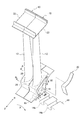
- FIG. 2 is a perspective view showing the configuration of the turbine rotor blade in the first embodiment of the present invention.
- FIG. 3 is a perspective view showing the configuration of the main part of the turbine rotor blade in the first embodiment of the present invention.
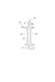
- FIG. 4 is a cross-sectional view taken along the line AA of FIG. 3 in the first embodiment of the present invention.
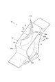
- FIG. 5 is a perspective view showing the configuration of the shield member in the first embodiment of the present invention.
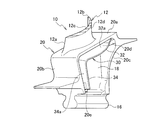
- FIG. 6 is a perspective view showing a state in which the shield member is attached to the turbine rotor blade in the first embodiment of the present invention.
- FIG. 7 is a top view showing a state in which the shield member is attached to the turbine rotor blade in the first embodiment of the present invention.
- FIG. 8 is a cross-sectional view showing a state where the shield member is attached to the turbine rotor blade in the first embodiment of the present invention.
- FIG. 9 is a cross-sectional view in the AA direction of FIG. 2 in the first embodiment of the present invention.
- FIG. 10 is a cross-sectional view in the BB direction of FIG. 2 in the first embodiment of the present invention.
- FIG. 11 is a perspective view showing the configuration of the shield member in the second embodiment of the present invention.
- FIG. 12 is a cross-sectional view showing a state in which the shield member is attached to the turbine rotor blade in the second embodiment of the present invention.
- FIG. 13 is a cross-sectional view showing a state in which a shield member is mounted between the platform portions of adjacent turbine blades in the second embodiment of the present invention.
- FIG. 14 is a perspective view showing the configuration of the shield member in the third embodiment of the present invention.
- FIG. 15 is a cross-sectional view showing a state in which the shield member is attached to the turbine rotor blade in the third embodiment of the present invention.
- FIG. 16 is a perspective view showing a configuration of a shield member in the fourth embodiment of the present invention.
- FIG. 17 is a cross-sectional view showing a state in which the shield member is attached to the turbine rotor blade in the fourth embodiment of the present invention.
- FIG. 18 is a perspective view showing the configuration of the shield member in the fifth embodiment of the present invention.
- FIG. 19 is a cross-sectional view showing a state in which the shield member is attached to the turbine rotor blade in the fifth embodiment of the present invention.
- FIG. 20 is a cross-sectional view showing a state in which a shield member is mounted between the platform portions of adjacent turbine blades in the fifth embodiment of the present invention.
- FIG. 21 is a cross-sectional view showing a state in which a shield member is mounted between the platform portions of adjacent turbine blades in the fifth embodiment of the present invention.
- FIG. 1 is a diagram showing a configuration of an aircraft turbofan engine 8.
- the aircraft turbofan engine 8 includes a plurality of stages of turbines such as a low-pressure turbine in order to extract energy from a combustion gas obtained by burning a working fluid such as air.
- Each stage of the turbine is composed of a plurality of turbine blades arranged around a turbine disk.
- FIG. 2 is a perspective view showing the configuration of the turbine rotor blade 10.
- FIG. 3 is a perspective view showing the configuration of the main part of the turbine rotor blade 10.
- FIG. 4 is a cross-sectional view in the AA direction of FIG.
- F indicates the upstream side of the combustion gas in the turbine axial direction
- R indicates the downstream side of the combustion gas in the turbine axial direction
- X indicates the rotational direction of the turbine rotor blade 10. Is shown.
- the low-pressure turbine blade is described, but the same applies to the high-pressure turbine blade.
- the turbine rotor blade 10 includes a blade portion 12, a dovetail portion 16 that is attached to the turbine disk 14, a shank portion 18 that connects the blade portion 12 and the dovetail portion 16, and the blade portion 12 and the shank portion 18. And a platform part 20 provided.
- the blade portion 12 is formed to extend in the longitudinal direction of the turbine blade 10.
- the blade 12 has a positive pressure surface 12c formed in a concave shape and a negative surface formed in a convex shape between a front edge 12a on the upstream side of the combustion gas and a rear edge 12b on the downstream side of the combustion gas. And a pressure surface 12d.
- a tip shroud 22 is provided on the upper end side of the wing portion 12.
- the dovetail portion 16 has a function of fitting with the disk groove 14 a of the turbine disk 14 and attaching the turbine blade 10 to the turbine disk 14.
- the dovetail portion 16 has a shape complementary to the disk groove 14a.
- the shank portion 18 has a function of connecting the wing portion 12 and the dovetail portion 16 and transmitting a load from the wing portion 12 to the dovetail portion 16.
- the shank portion 18 is provided on the base end side in the longitudinal direction of the wing portion 12, and is formed to extend from the base end side of the wing portion 12 to the dovetail portion 16.
- the shank portion 18 is formed in a curved shape corresponding to the shape of the wing portion 12.
- the side surface of the shank portion 18 is formed in a concave shape on the pressure surface side of the wing portion 12 and is formed in a convex shape on the suction surface side of the wing portion 12.
- pockets 24 formed in a recessed shape are provided for weight reduction and the like.
- the platform part 20 is provided integrally connected between the blade part 12 and the shank part 18 and has a function of shielding combustion gas flowing in the turbine axial direction.
- the platform portion 20 includes a platform portion main body 20 a formed to extend in a direction intersecting with the longitudinal direction of the turbine rotor blade 10.
- the platform portion 20 has a front skirt 20b provided along the longitudinal direction of the turbine rotor blade 10 on the front edge side of the platform portion main body 20a.
- the platform part 20 has the back skirt 20c provided along the longitudinal direction of the turbine rotor blade 10 in the rear edge side of the platform part main body 20a.
- the inner surface of the rear skirt 20c is formed by a convex curved surface that is formed so as to be convex toward the front edge side.
- the inner surface of the platform portion main body 20a and the inner surface of the front skirt 20b are provided with a platform portion main body side fitting groove 20d and a front skirt side fitting groove 20e for fitting a shield member 30 described later. Yes.
- the platform portion main body side fitting groove 20d is formed to extend in the width direction intersecting the longitudinal direction of the platform portion main body 20a.
- the front skirt side fitting groove 20e is formed to extend in the width direction intersecting the longitudinal direction of the front skirt 20b.
- the turbine rotor blade 10 Since the turbine rotor blade 10 is exposed to high temperature by combustion gas, it is made of a lightweight material having excellent high-temperature strength, such as a ceramic-based composite material, a Ni-based superalloy, or a TiAl alloy.
- the turbine rotor blade 10 is manufactured by, for example, unidirectional solidification casting or single crystal casting.
- FIG. 5 is a perspective view showing the configuration of the shield member 30.
- FIG. 6 is a perspective view showing a state in which the shield member 30 is attached to the turbine rotor blade 10.
- FIG. 7 is a top view showing a state in which the shield member 30 is attached to the turbine rotor blade 10.
- FIG. 8 is a cross-sectional view showing a state where the shield member 30 is attached to the turbine rotor blade 10.
- the shield member 30 is disposed in a gap between the platform portions 20 of the adjacent turbine blades 10 and is formed of a ceramic matrix composite material, and has a function of shielding the gap between the platform portions 20.
- the shield member 30 includes a shield member main body 32 and a front edge side shield portion 34 provided at one end in the longitudinal direction of the shield member main body 32.
- the shield member main body 32 is formed in an elongated shape, and along the inner surface of the platform portion main body 20a of the adjacent turbine blade 10 between the shank portions 18 connected to the platform portion 20 of the adjacent turbine blade 10, It has the 1st shield surface 32a which contacts the inner surface of the platform part main body 20a.
- the first shield surface 32a is brought into contact with the inner surface of each platform portion main body 20a along the inner surface of each platform portion main body 20a of the adjacent turbine moving blade 10 by applying centrifugal force when the turbine moving blade 10 rotates. By this, it has the function which shields the clearance gap between the platform part main bodies 20a of the turbine blade 10 which adjoins.
- the first shield surface 32a is formed in a substantially planar shape so as to correspond to the inner surface of each platform portion main body 20a of the adjacent turbine blade 10.
- the shield member main body 32 is formed to be curved in a plane in the longitudinal direction of the shield member main body 32 so as to correspond to the shape of the side surface of the shank portion 18 of the adjacent turbine rotor blade 10. More specifically, the shield member main body 32 is formed such that one side edge 32b in the width direction intersecting the longitudinal direction of the shield member main body 32 is curved in a convex shape, and the other side edge 32c is concave. It is formed to be curved.
- the convex side edge 32 b of the shield member main body 32 corresponds to the concave side surface of the shank portion 18, and the concave side edge 32 c of the shield member main body 32 is , Corresponding to the convex side surface of the shank portion 18.
- the shield member main body 32 has a shield member main body side fitting portion 32d that fits in the platform portion main body side fitting groove 20d at the other end in the longitudinal direction of the shield member main body 32.
- the shield member main body 32 is easily positioned by fitting the shield member main body side fitting portion 32d with the platform portion main body side fitting groove 20d.
- the length in the longitudinal direction of the shield member main body 32 is set to be substantially the same as the length from the front edge side to the rear edge side of the platform portion main body 20a, and is, for example, 50 mm to 60 mm.
- the width of the shield member main body 32 is set to be larger than the gap between the platform portion main bodies 20a of the adjacent turbine blades 10 and smaller than the interval between the shank portions 18 of the adjacent turbine blades 10.
- the width of the shield member main body 32 may be the same in the longitudinal direction of the shield member main body 32 or may be different.
- the width of the shield member main body 32 is, for example, 20 mm to 30 mm.
- the thickness of the shield member main body 32 is set to a thickness at which rigidity necessary for maintaining the shape of the shield member main body 32 is obtained.
- the thickness of the shield member main body 32 is, for example, 1 mm to 2 mm.
- the front edge side shield portion 34 is formed in an elongated shape, and one end in the longitudinal direction is integrally provided at one end in the longitudinal direction of the shield member main body 32 with respect to the shield member main body 32.
- the leading edge shield part 34 is located between the shank parts 18 of the adjacent turbine blades 10 along the inner surface of the front skirt 20b of the adjacent turbine blades 10 and is in contact with the inner surface of the front skirt 20b. have.
- the second shield surface 34a is brought into contact with the inner surface of each front skirt 20b along the inner surface of each front skirt 20b of the adjacent turbine blade 10 by applying centrifugal force when the turbine blade 10 rotates. , And has a function of shielding a gap between the front skirts 20b of the adjacent turbine rotor blades 10b.
- the second shield surface 34 a is formed in a planar shape, a curved surface shape, or the like corresponding to the inner surface of the front skirt 20 b of the adjacent turbine rotor blade 10.
- one side edge 34b and the other side edge 34c in the width direction intersecting with the longitudinal direction of the front edge side shield part 34 may be formed substantially linearly or curved. It may be formed.
- the front edge side shield part 34 has a front edge side shield part side fitting part 34d fitted to the front skirt side fitting groove 20e at the other end in the longitudinal direction of the front edge side shield part 34.
- the front edge side shield part 34 is easily positioned by fitting the front edge side shield part side fitting part 34d into the front skirt side fitting groove 20e.
- the length of the front edge side shield part 34 in the longitudinal direction is set to be substantially the same as the length from the wing part 12 side to the dovetail part 16 side of the front skirt 20b.
- the width of the front edge side shield portion 34 is set to be larger than the gap between the front skirts 20b of the adjacent turbine blades 10 and smaller than the interval between the shank portions 18 of the adjacent turbine blades 10.
- variety of the front edge side shield part 34 you may make it the same in the longitudinal direction of the front edge side shield part 34, and may make it differ.
- variety of the front edge side shield part 34 they are 20 mm to 30 mm, for example.
- the thickness of the leading edge shield part 34 is set to a thickness that provides the rigidity necessary for maintaining the shape of the leading edge shield part 34.
- the thickness of the front edge side shield part 34 is, for example, 1 mm to 2 mm. Note that the thickness of the front edge side shield portion 34 may be the same as that of the shield member main body 32.
- the shield member 30 is formed of a ceramic matrix composite material.
- the ceramic matrix composite material is a ceramic fiber reinforced ceramic composite material in which a ceramic matrix is reinforced with ceramic fibers.
- As the ceramic matrix composite material for example, a SiC / SiC composite material in which a SiC matrix is reinforced with SiC fibers, a SiC / Al 2 O 3 composite material in which a SiC matrix is reinforced with Al 2 O 3 fibers, or the like can be used. is there. Since the ceramic matrix composite material is excellent in heat resistance and oxidation resistance, it is possible to suppress damage such as deformation and oxidation due to heat exposure even when the shield member 30 is exposed to combustion gas.
- the ceramic matrix composite is lighter than a heat-resistant alloy (for example, Ni-base superalloy or TiAl alloy), the aircraft turbofan engine 8 and the like can be reduced in weight. Furthermore, since the ceramic matrix composite material is reinforced with ceramic fibers and has excellent toughness and the like, even when it receives an impact due to the rotation of the turbine rotor blade 10 or the like, breakage is suppressed.
- a heat-resistant alloy for example, Ni-base superalloy or TiAl alloy
- a preform corresponding to the shape of the shield member 30 is formed by trimming or stitching a two-dimensional fabric or a three-dimensional fabric made of ceramic fibers.
- the ceramic fiber SiC fiber, Al 2 O 3 fiber, or the like can be used.
- the preform is placed in a mold, the matrix polymer material is filled into the mold, and the preform is impregnated with the polymer material.
- the preform impregnated with the polymer raw material is heated and fired to be ceramicized to form a ceramic matrix such as SiC.
- a ceramic matrix such as SiC can be formed by a thermal decomposition reaction of a raw material gas.
- a ceramic matrix such as SiC can be formed by reacting the preform after impregnating a mixed powder of Si and C, for example. In this way, the shield member 30 can be formed of a ceramic matrix composite material.
- FIG. 9 is a cross-sectional view in the AA direction of FIG.
- FIG. 10 is a cross-sectional view in the BB direction of FIG.
- the shield member 30 is mounted in the gaps 36 and 38 between the platform portions 20 of the adjacent turbine blades 10. More specifically, the shield member body side fitting portion 32d is fitted into the platform portion body side fitting groove 20d, and the front edge side shield portion side fitting portion 34d is fitted into the front skirt side fitting groove 20e. Then, the shield member 30 is positioned and mounted. Accordingly, the shield member 30 is disposed to face the gaps 36 and 38 between the platform portions 20 of the adjacent turbine blades 10.
- the turbine rotor blade 10 receives a combustion gas flow that flows in the turbine axial direction, so that the turbine rotor blade 10 rotates integrally with the turbine disk 14. Due to this rotational motion, centrifugal force acts on the turbine rotor blade 10. Due to this centrifugal force, the shield members 30 disposed in the gaps 36 and 38 between the platform portions 20 of the adjacent turbine rotor blades 10 come into contact with and closely contact with the inner surface of the platform portion 20. The gaps 36 and 38 are shielded.
- the first shield surface of the shield member main body 32 is formed on the inner surface of the platform portion main body 20a. Since 32a contacts and closely_contact
- the second shield surface 34a of the front edge side shield portion 34 contacts the inner surface of the front skirt 20b along the inner surface of the front skirt 20b. Since it adheres closely, the gap 38 between the front skirts 20b is shielded.
- the combustion gas is prevented from flowing from the gap 36 between the platform body 20a and the gap 38 between the front skirts 20b, so that it is possible to suppress the heat exposure of the turbine disk 14 due to the combustion gas. .
- the gap between the platform portions of the adjacent turbine blades can be obtained by disposing the shield member formed of the ceramic matrix composite material in the gap between the platform portions of the adjacent turbine blades. Therefore, it is possible to suppress the inflow of combustion gas from the turbine, so that the thermal exposure of the turbine disk can be suppressed. Moreover, since the shield member is formed of a ceramic matrix composite material, it is possible to suppress damage due to heat exposure even if the shield member is exposed to combustion gas.
- the shield member body is formed curved in a plane corresponding to the side surface of the shank portion. Therefore, interference between the shield member main body and the shank portion is suppressed, and the shield performance can be improved.
- the shield member main body side fitting portion is fitted into the platform portion main body side fitting groove, and the front edge side shield portion side fitting portion is fitted into the front skirt side fitting groove, thereby being adjacent to each other.
- the shield member can be easily mounted between the platform portions of the turbine blades, and the shield member can be easily positioned and arranged with high accuracy.
- FIG. 11 is a perspective view showing the configuration of the shield member 40 of the second embodiment.
- FIG. 12 is a cross-sectional view showing a state where the shield member 40 of the second embodiment is mounted on the turbine rotor blade 10.
- FIG. 13 is a cross-sectional view showing a state where the shield member 40 of the second embodiment is mounted between the platform portions 20 of the adjacent turbine blades 10.
- FIG. 13 is a view corresponding to FIG. 9 of the first embodiment.
- symbol is attached
- the shield member 40 of the second embodiment is provided on each of a part of both sides 32b and 32c in the longitudinal direction of the shield member main body 32, and is formed to protrude in the width direction intersecting the longitudinal direction of the shield member main body 32.
- the shield member 30 is different from the shield member 30 of the first embodiment in that it has a restricting portion 42 that contacts the side surface of the shank portion 18 in the adjacent turbine rotor blade 10 and restricts the movement in the width direction.
- the restricting portion 42 shields by surface contact or line contact with the side surface of each shank portion 18 of the adjacent turbine blade 10. It has a function of holding the member 40 and restricting the movement of the shield member 40 in the width direction. As a result, the movement of the shield member 40 in the width direction is restricted, so that the shield member 40 is prevented from falling off and the positioning accuracy of the shield member 40 is improved in the initial stage of the rotational movement of the turbine rotor blade 10. .
- the regulating portion 42 protrudes in the width direction intersecting with the longitudinal direction of the shield member main body 32 and is curved toward the back side of the first shield surface 32a.
- the shape of the restricting portion 42 can be rectangular, triangular, round, or the like.
- the regulating part 42 may be provided at the same position in the longitudinal direction of the shield member main body 32 or may be provided at a different position.
- the restricting portion 42 may be provided at each of the side edges 32b and 32c, or may be provided at a plurality of locations. Moreover, about the control part 42, you may make it the quantity provided in one side edge 32b and the other side edge 32c differ.
- the center part of the longitudinal direction of the shield member main body 32 may be sufficient, the one end side of a longitudinal direction may be sufficient, and the other end side may be sufficient.
- the shield member 40 is formed of a ceramic matrix composite material
- a preform corresponding to the shape of the shield member 40 is formed by trimming or stitching a two-dimensional fabric or a three-dimensional fabric made of ceramic fibers. .
- the preform is placed in the mold, and the portion corresponding to the restricting portion 42 is curved and set in the mold. Since the formation of the ceramic matrix is the same as that of the shield member 30 of the first embodiment, a detailed description thereof will be omitted.
- the effect of the shield member of the first embodiment is obtained, and when the shield member is mounted in the gap between the platform portions of the adjacent turbine blades, the restriction portion of the shield member main body is adjacent to the turbine. Since the shield member is held in contact with the side surface of each shank portion of the rotor blade, the movement of the shield member in the width direction is restricted, so that the shield member is prevented from falling off and the positioning accuracy of the shield member is improved. To do.
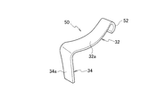
- FIG. 14 is a perspective view showing the configuration of the shield member 50 of the third embodiment.
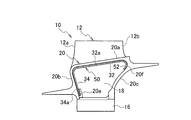
- FIG. 15 is a cross-sectional view showing a state where the shield member 50 of the third embodiment is mounted on the turbine rotor blade 10.
- symbol is attached
- the rear skirt 20c of the platform portion 20 is provided on the inner surface of the rear skirt 20c, and includes a holding portion 20f that holds the other end in the longitudinal direction of the shield member main body 32 in the shield member 50 of the third embodiment.
- the holding portion 20f is formed of a part of the inner surface of the rear skirt 20c, and is formed of a convex curved holding surface that is convexly curved toward the front edge side.
- the shield member 50 of the third embodiment is provided at the other end in the longitudinal direction of the shield member main body 32, is formed to be curved toward the back side of the first shield surface 32a, and is a rear skirt of the adjacent turbine blade 10.
- the shield member 30 is different from the shield member 30 of the first embodiment in having a curved portion 52 that contacts the holding portion 20f of 20c.
- the curved surface 52 provided at the other end of the shield member main body 32 is the holding surface that is the holding portion 20f of the rear skirt 20c.
- the shield member main body 32 is held by surface contact or line contact along. This eliminates the need for the platform portion main body side fitting groove 20d provided in the platform portion main body 20a to hold the shield member main body 32, thereby further simplifying the configuration of the platform portion 20 and the turbine rotor blade 10 Can be easily manufactured.
- the shield member 50 is formed of a ceramic matrix composite material
- a preform corresponding to the shape of the shield member 50 is formed by trimming or stitching a two-dimensional fabric or a three-dimensional fabric made of ceramic fibers. .
- the preform is placed in the mold, and the portion corresponding to the bending portion 52 is bent and set in the mold. Since the formation of the ceramic matrix is the same as that of the shield member 30 of the first embodiment, a detailed description thereof will be omitted.
- the effect of the shield member of the first embodiment is achieved, and the platform part body side fitting groove provided in the platform part body for holding the shield member body is not necessary.
- the configuration is further simplified, and the manufacture of the turbine rotor blade can be facilitated.
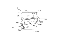
- FIG. 16 is a perspective view showing the configuration of the shield member 60 of the fourth embodiment.
- FIG. 17 is a cross-sectional view showing a state in which the shield member 60 of the fourth embodiment is mounted on the turbine rotor blade 10.
- symbol is attached
- the rear skirt 20c of the platform portion 20 is provided on the inner surface of the rear skirt 20c, and includes a holding portion 20f that holds the other end in the longitudinal direction of the shield member main body 32 in the shield member 60 of the fourth embodiment.
- the shield member 60 of the fourth embodiment is different from that of the first embodiment in that it includes the restriction portion 42 of the shield member 40 of the second embodiment and the curved portion 52 of the shield member 50 of the third embodiment. This is different from the shield member 30.
- the shield member 60 is formed of a ceramic matrix composite material
- a preform corresponding to the shape of the shield member 60 is formed by trimming or stitching a two-dimensional fabric or a three-dimensional fabric made of ceramic fibers. .
- the preform is placed in the mold, and the portions corresponding to the restricting portion 42 and the bending portion 52 are bent and set in the die. Since the formation of the ceramic matrix is the same as that of the shield member 30 of the first embodiment, a detailed description thereof will be omitted.
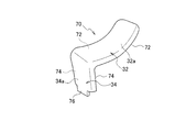
- FIG. 18 is a perspective view showing the configuration of the shield member 70 of the fifth embodiment.
- FIG. 19 is a cross-sectional view showing a state in which the shield member 70 of the fifth embodiment is mounted on the turbine rotor blade 10.
- FIG. 20 is a cross-sectional view showing a state in which the shield member 70 of the fifth embodiment is mounted between the platform portions 20 of the adjacent turbine blades 10.
- FIG. 21 is a cross-sectional view showing a state in which the shield member 70 of the fifth embodiment is mounted between the platform portions 20 of adjacent turbine blades 10.
- FIG. 20 is a view corresponding to FIG. 9 of the first embodiment.
- FIG. 9 the first embodiment.
- FIG. 21 is a view corresponding to FIG. 10 of the first embodiment.
- the shield member 70 of the fifth embodiment is mounted in place of the shield member 30 of the first embodiment in the BB direction. It is sectional drawing.
- symbol is attached
- the rear skirt 20c of the platform portion 20 is provided on the inner surface of the rear skirt 20c, and includes a holding portion 20f that holds the other end in the longitudinal direction of the shield member main body 32 in the shield member 70 of the fifth embodiment.
- the shield member 70 of the fifth embodiment is provided over the entire length of both sides in the longitudinal direction of the shield member main body 32, protrudes in the width direction intersecting with the longitudinal direction of the shield member main body 32, and is formed on the first shield surface 32a. It has a first contact portion 72 that is curved toward the back surface side and contacts the side surface of the shank portion 18 in the adjacent turbine rotor blade 10 and the holding portion 20f of the rear skirt 20c.
- the shield member 70 is provided over the entire length of both sides of the front edge side shield portion 34 in the longitudinal direction, protrudes in the width direction intersecting with the longitudinal direction of the front edge side shield portion 34, and the back surface of the second shield surface 34 a. It has a second contact portion 74 that is curved toward the side and contacts the side surface of the shank portion 18 in the adjacent turbine blade 10. As described above, the shield member 70 of the fifth embodiment is different from the shield member 30 of the first embodiment in that it includes the first contact portion 72 and the second contact portion 74.
- the shield member 70 is provided in the shield member main body 32 when the shield member 70 is mounted in the gaps 36 and 38 between the platform portions 20 of the adjacent turbine rotor blades 10 and the shield member 70 is disposed to face the gaps 36 and 38.
- the first contact portion 72 is in surface contact or line contact with the side surface of each shank portion 18 of the adjacent turbine blade 10, and the second contact portion 74 provided on the leading edge side shield portion 34 is adjacent to the adjacent turbine blade 10.
- the shield member 70 is held in surface contact or line contact with the side surface of each shank portion 18.
- the shield member body 32 is provided.
- the shield member main body 32 is held by the rear of the first contact portion 72 thus made contacting the holding portion 20f of the rear skirt 20c. This eliminates the need for the platform portion main body side fitting groove 20d provided in the platform portion main body 20a to hold the shield member main body 32, thereby further simplifying the configuration of the platform portion 20 and the turbine rotor blade 10 Can be easily manufactured.
- the other end on the dovetail portion 16 side of the front edge side shield portion 34 is formed so as to protrude in order to be fitted with the front skirt side fitting groove 20e provided on the inner surface of the front skirt 20b.
- a leading edge shield portion side fitting portion 76 is provided.
- a preform corresponding to the shape of the shield member 70 is formed by trimming or stitching a two-dimensional fabric or a three-dimensional fabric made of ceramic fibers. While forming a preform in a metal mold
- the first contact portion provided in the shield member main body has the effect of the shield member of the first embodiment, and when the shield member is mounted in the gap between the platform portions of the adjacent turbine blades. However, it contacts with the side surface of the shank part of an adjacent turbine blade, and the 2nd contact part provided in the front edge side shield part contacts the side surface of the shank part of an adjacent turbine blade, and hold
- the first contact portion provided on the shield member main body comes into contact with the holding portion of the rear skirt and the shield member. Since the main body is held, the platform part main body side fitting groove provided in the platform part main body is not required, and therefore, the manufacture of the turbine rotor blade can be facilitated.
- the present invention is useful for jet engines such as aircraft turbofan engines because it can shield the gaps between the platforms of adjacent turbine blades.
Landscapes
- Engineering & Computer Science (AREA)
- Chemical & Material Sciences (AREA)
- Mechanical Engineering (AREA)
- General Engineering & Computer Science (AREA)
- Combustion & Propulsion (AREA)
- Ceramic Engineering (AREA)
- Manufacturing & Machinery (AREA)
- Chemical Kinetics & Catalysis (AREA)
- Materials Engineering (AREA)
- Structural Engineering (AREA)
- Organic Chemistry (AREA)
- Architecture (AREA)
- Turbine Rotor Nozzle Sealing (AREA)
Abstract
シールド部材(30)は、隣接するタービン動翼(10)のプラットフォーム部(20)の間の隙間に配置され、セラミックス基複合材料で形成されており、プラットフォーム部(20)の間の隙間をシールドする。
Description
本発明は、シールド部材及びそれを用いたジェットエンジンに係り、特に、航空機用ターボファンエンジン等のタービン動翼に用いられるシールド部材及びそれを用いたジェットエンジンに関する。
航空機用ターボファンエンジン等では、燃焼ガスからエネルギを取り出すべく複数段のタービンを備えている。各段のタービンは、複数のタービン動翼で構成されている。タービン動翼は、翼部と、チップシュラウドと、プラットフォーム部と、ダブテール部と、を備えている。特許文献1には、これらの構成を備えたタービン動翼が記載されている。
ところで、タービン動翼において、例えば低圧タービンでは、チップシュラウドとプラットフォーム部とにより囲まれた空間を燃焼ガスが流れ、翼部がこれを受けて回転エネルギに変換し、タービンディスクに伝達する。この際に、隣接するタービン動翼のプラットフォーム部の間の隙間から燃焼ガスが入り込むと、タービンディスクが燃焼ガスにより熱曝露されて損傷を受ける可能性がある。
また、高圧タービンでは、ケーシングに固定されたシュラウドとプラットフォーム部とにより囲まれた空間を燃焼ガスが流れ、翼部がこれを受けて回転エネルギに変換し、タービンディスクに伝達する。この際に、隣接するタービン動翼のプラットフォーム部の間の隙間から燃焼ガスが入り込むと、低圧タービンの場合と同様に、タービンディスクが燃焼ガスにより熱曝露されて損傷を受ける可能性がある。
そこで本発明の目的は、隣接するタービン動翼のプラットフォーム部の間の隙間をシールド可能なシールド部材及びそれを用いたジェットエンジンを提供することである。
本発明に係るシールド部材は、隣接するタービン動翼のプラットフォーム部の間の隙間に配置され、セラミックス基複合材料で形成されており、前記プラットフォーム部の間の隙間をシールドする。
本発明に係るシールド部材において、前記プラットフォーム部は、前記タービン動翼の長手方向と交差する方向に延びて形成されているプラットフォーム部本体と、前記プラットフォーム部本体の前縁側に設けられる前方スカートと、を有し、前記シールド部材は、細長く形成されており、前記隣接するタービン動翼のプラットフォーム部と接続されたシャンク部の間において、前記隣接するタービン動翼のプラットフォーム部本体の内面に沿って、前記プラットフォーム部本体の内面に接触し、前記プラットフォーム部本体の間の隙間をシールドする第1シールド面を有するシールド部材本体と、細長く形成されており、前記シールド部材本体の長手方向の一端に、前記シールド部材本体に対して屈曲して長手方向の一端が一体的に設けられ、前記隣接するタービン動翼のシャンク部の間において、前記隣接するタービン動翼の前方スカートの内面に沿って、前記前方スカートの内面に接触し、前記前方スカートの間の隙間をシールドする第2シールド面を有する前縁側シールド部と、を備える。
本発明に係るシールド部材は、前記シールド部材本体における長手方向の両側の一部に各々設けられ、前記シールド部材本体の長手方向と交差する幅方向に突出すると共に、前記第1シールド面の裏面側に向けて湾曲して形成され、前記隣接するタービン動翼のシャンク部の側面に接触し、前記幅方向の動きを規制する規制部を有している。
本発明に係るシールド部材において、前記プラットフォーム部は、前記プラットフォーム部本体の後縁側に設けられる後方スカートを有し、前記後方スカートは、前記後方スカートの内面に設けられ、前記シールド部材本体の長手方向の他端を保持する保持部を含み、前記シールド部材は、前記シールド部材本体の長手方向の他端に設けられ、前記第1シールド面の裏面側に向けて湾曲して形成され、前記隣接するタービン動翼の前記後方スカートの保持部に接触する湾曲部を有している。
本発明に係るシールド部材において、前記プラットフォーム部は、前記プラットフォーム部本体の後縁側に設けられる後方スカートを有し、前記後方スカートは、前記後方スカートの内面に設けられ、前記シールド部材本体の長手方向の他端を保持する保持部を含み、前記シールド部材は、前記シールド部材本体における長手方向の両側の全長に亘って設けられ、前記シールド部材本体の長手方向と交差する幅方向に突出すると共に、前記第1シールド面の裏面側へ向けて湾曲して形成され、前記隣接するタービン動翼におけるシャンク部の側面と、前記後方スカートの保持部とに接触する第1接触部と、前記前縁側シールド部における長手方向の両側の全長に亘って設けられ、前記前縁側シールド部の長手方向と交差する幅方向に突出すると共に、前記第2シールド面の裏面側へ向けて湾曲して形成され、前記隣接するタービン動翼におけるシャンク部の側面に接触する第2接触部と、を有する。
本発明に係るシールド部材において、前記シャンク部は、前記タービン動翼の翼部の形状に対応して湾曲して形成されており、前記シールド部材本体は、前記隣接するタービン動翼のシャンク部の側面に対応して平面内で湾曲して形成されている。
本発明に係るシールド部材において、前記プラットフォーム部は、前記プラットフォーム部本体の内面に設けられるプラットフォーム部本体側嵌合溝と、前記前方スカートの内面に設けられる前方スカート側嵌合溝と、を有し、前記シールド部材本体は、前記シールド部材本体の長手方向の他端に設けられ、前記プラットフォーム部本体側嵌合溝と嵌合するシールド部材本体側嵌合部を有し、前記前縁側シールド部は、前記前縁側シールド部の長手方向の他端に設けられ、前記前方スカート側嵌合溝と嵌合する前縁側シールド部側嵌合部を有する。
本発明に係るシールド部材において、前記プラットフォーム部は、前記前方スカートの内面に設けられる前方スカート側嵌合溝を有しており、前記前縁側シールド部は、前記前縁側シールド部の長手方向の他端に設けられ、前記前方スカート側嵌合溝と嵌合する前縁側シールド部側嵌合部を有する。
本発明に係るジェットエンジンは、前記シールド部材を用いる。
上記構成のシールド部材及びそれを用いたジェットエンジンによれば、シールド部材は、隣接するタービン動翼のプラットフォーム部の間の隙間に配置され、セラミックス基複合材料で形成されていることから、燃焼ガスに対して耐熱性を有していると共に、プラットフォーム部の間の隙間から入り込む燃焼ガスをシールド可能であるので、タービンディスクの燃焼ガスによる損傷を抑制することができる。
以下に本発明の実施形態について図面を用いて詳細に説明する。
[第1実施形態]
本発明の第1実施形態について図面を用いて詳細に説明する。まず、航空機用ターボファンエンジン等のジェットエンジンに使用されるタービン動翼について説明する。図1は、航空機用ターボファンエンジン8の構成を示す図である。航空機用ターボファンエンジン8は、空気等の作動流体を燃焼させた燃焼ガスからエネルギを取り出すべく低圧タービン等の複数段のタービンを備えている。各段のタービンは、タービンディスクの周囲に配列された複数のタービン動翼で構成されている。
本発明の第1実施形態について図面を用いて詳細に説明する。まず、航空機用ターボファンエンジン等のジェットエンジンに使用されるタービン動翼について説明する。図1は、航空機用ターボファンエンジン8の構成を示す図である。航空機用ターボファンエンジン8は、空気等の作動流体を燃焼させた燃焼ガスからエネルギを取り出すべく低圧タービン等の複数段のタービンを備えている。各段のタービンは、タービンディスクの周囲に配列された複数のタービン動翼で構成されている。
図2は、タービン動翼10の構成を示す斜視図である。図3は、タービン動翼10の主要部の構成を示す斜視図である。図4は、図3のA-A方向の断面図である。なお、図2において、Fは、タービン軸方向における燃焼ガスの上流側を示しており、Rは、タービン軸方向における燃焼ガスの下流側を示しており、Xは、タービン動翼10の回転方向を示している。なお、ここでは,低圧タービン動翼について説明しているが,高圧タービン動翼についても同様である。
タービン動翼10は、翼部12と、タービンディスク14に取り付けるためのダブテール部16と、翼部12とダブテール部16とを連結するシャンク部18と、翼部12とシャンク部18との間に設けられるプラットフォーム部20と、を備えている。
翼部12は、タービン動翼10の長手方向に延びて形成されている。翼部12は、燃焼ガスの上流側となる前縁12aと、燃焼ガスの下流側となる後縁12bとの間に、凹面状に形成された正圧面12cと、凸面状に形成された負圧面12dとを有している。翼部12の上端側には、チップシュラウド22が設けられている。
ダブテール部16は、タービンディスク14のディスク溝14aと嵌合し、タービン動翼10をタービンディスク14に取り付ける機能を有している。ダブテール部16は、ディスク溝14aと相補的な形状を有している。
シャンク部18は、翼部12とダブテール部16とを連結し、翼部12からダブテール部16へ荷重を伝達する機能を有している。シャンク部18は、翼部12の長手方向の基端側に設けられており、翼部12の基端側からダブテール部16へ延びて形成されている。
シャンク部18は、翼部12の形状に対応して湾曲して形成されている。シャンク部18の側面については、翼部12の正圧面側では凹状に形成されており、翼部12の負圧面側では凸状に形成されている。シャンク部18の両側には、軽量化等のために、窪み状に形成されたポケット24が各々設けられている。
プラットフォーム部20は、翼部12とシャンク部18との間に一体的に接続されて設けられており、タービン軸方向に流れる燃焼ガスをシールドする機能を有している。プラットフォーム部20は、タービン動翼10の長手方向に対して交差する方向に延びて形成されているプラットフォーム部本体20aを備えている。
プラットフォーム部20は、プラットフォーム部本体20aの前縁側にタービン動翼10の長手方向に沿って設けられた前方スカート20bを有している。また、プラットフォーム部20は、プラットフォーム部本体20aの後縁側にタービン動翼10の長手方向に沿って設けられた後方スカート20cを有している。後方スカート20cの内面は、前縁側に向けて凸状に湾曲して形成された凸曲面で構成されている。なお、後方スカート20cの内面については、凸曲面だけでなく、傾斜平面や垂直平面等で構成することも可能である。
プラットフォーム部本体20aの内面と、前方スカート20bの内面とには、後述するシールド部材30を嵌合するためのプラットフォーム部本体側嵌合溝20dと、前方スカート側嵌合溝20eとが設けられている。プラットフォーム部本体側嵌合溝20dは、プラットフォーム部本体20aの長手方向と交差する幅方向に延びて形成されている。前方スカート側嵌合溝20eは、前方スカート20bの長手方向と交差する幅方向に延びて形成されている。
タービン動翼10は、燃焼ガスにより高温に曝されるので、セラミックス基複合材料、Ni基超合金、TiAl合金等の軽量で高温強度に優れた材料で形成されている。タービン動翼10は、例えば、一方向凝固鋳造や単結晶鋳造等により製造される。
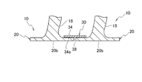
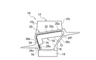
次に、シールド部材について説明する。図5は、シールド部材30の構成を示す斜視図である。図6は、シールド部材30をタービン動翼10に装着した状態を示す斜視図である。図7は、シールド部材30をタービン動翼10に装着した状態を示す上面図である。図8は、シールド部材30をタービン動翼10に装着した状態を示す断面図である。
シールド部材30は、隣接するタービン動翼10のプラットフォーム部20の間の隙間に配置され、セラミックス基複合材料で形成されており、プラットフォーム部20の間の隙間をシールドする機能を有している。シールド部材30は、シールド部材本体32と、シールド部材本体32の長手方向の一端に設けられた前縁側シールド部34と、を備えている。
シールド部材本体32は、細長く形成されており、隣接するタービン動翼10のプラットフォーム部20と接続されたシャンク部18の間において、隣接するタービン動翼10のプラットフォーム部本体20aの内面に沿って、プラットフォーム部本体20aの内面に接触する第1シールド面32aを有している。
第1シールド面32aは、タービン動翼10の回転時に遠心力が作用することで、隣接するタービン動翼10の各プラットフォーム部本体20aの内面に沿って、各プラットフォーム部本体20aの内面に接触することにより、隣接するタービン動翼10のプラットフォーム部本体20aの間の隙間をシールドする機能を有している。第1シールド面32aは、隣接するタービン動翼10の各プラットフォーム部本体20aの内面に対応させて、略平面状に形成されている。
シールド部材本体32は、隣接するタービン動翼10のシャンク部18の側面の形状に対応させるために、シールド部材本体32の長手方向の平面内で湾曲して形成されている。より詳細には、シールド部材本体32は、シールド部材本体32の長手方向に対して交差する幅方向の一方の側縁32bが凸状に湾曲して形成されており、他方の側縁32cが凹状に湾曲して形成されている。
隣接するタービン動翼10にシールド部材30を装着する場合において、シールド部材本体32の凸状の側縁32bがシャンク部18の凹状の側面に対応し、シールド部材本体32の凹状の側縁32cが、シャンク部18の凸状の側面に対応している。これにより、シャンク部18の側面が翼部12の形状に対応して湾曲して形成されている場合でも、シールド部材本体32とシャンク部18との干渉を抑えられるので、シールド性能を向上させることができる。
シールド部材本体32は、シールド部材本体32の長手方向の他端に、プラットフォーム部本体側嵌合溝20dと嵌合するシールド部材本体側嵌合部32dを有している。シールド部材本体側嵌合部32dをプラットフォーム部本体側嵌合溝20dと嵌合することにより、シールド部材本体32が容易に位置決めされる。
シールド部材本体32の長手方向の長さについては、プラットフォーム部本体20aの前縁側から後縁側までの長さと略同じに設定され、例えば、50mmから60mmである。
シールド部材本体32の幅については、隣接するタービン動翼10のプラットフォーム部本体20aの間の隙間より大きく、隣接するタービン動翼10のシャンク部18の間の間隔より小さく設定される。シールド部材本体32の幅については、シールド部材本体32の長手方向で同じとしてもよいし、異なるようにしてもよい。シールド部材本体32の幅については、例えば、20mmから30mmである。
シールド部材本体32の厚みについては、シールド部材本体32の形状を保持するために必要な剛性が得られる厚みに設定される。シールド部材本体32の厚みについては、例えば、1mmから2mmである。
前縁側シールド部34は、細長く形成されており、シールド部材本体32の長手方向の一端に、シールド部材本体32に対して屈曲して長手方向の一端が一体的に設けられている。前縁側シールド部34は、隣接するタービン動翼10のシャンク部18の間において、隣接するタービン動翼10の前方スカート20bの内面に沿って、前方スカート20bの内面に接触する第2シールド面34aを有している。
第2シールド面34aは、タービン動翼10の回転時に遠心力が作用することで、隣接するタービン動翼10の各前方スカート20bの内面に沿って、各前方スカート20bの内面に接触することにより、隣接するタービン動翼10の前方スカート20bの間の隙間をシールドする機能を有している。第2シールド面34aは、隣接するタービン動翼10の前方スカート20bの内面に対応して、平面状や曲面状等に形成されている。
前縁側シールド部34では、前縁側シールド部34の長手方向に対して交差する幅方向の一方の側縁34bと他方の側縁34cとが略直線状に形成されていてもよいし、湾曲して形成されていてもよい。
前縁側シールド部34は、前縁側シールド部34の長手方向の他端に、前方スカート側嵌合溝20eと嵌合する前縁側シールド部側嵌合部34dを有している。前縁側シールド部側嵌合部34dを前方スカート側嵌合溝20eに嵌合させることにより、前縁側シールド部34が容易に位置決めされる。
前縁側シールド部34の長手方向の長さについては、前方スカート20bの翼部12側からダブテール部16側までの長さと略同じ長さに設定される。前縁側シールド部34の長手方向の長さについては、例えば、20mmから30mmである。
前縁側シールド部34の幅については、隣接するタービン動翼10の前方スカート20bの間の隙間より大きく、隣接するタービン動翼10のシャンク部18の間の間隔より小さく設定される。前縁側シールド部34の幅については、前縁側シールド部34の長手方向で同じとしてもよいし、異なるようにしてもよい。前縁側シールド部34の幅については、例えば、20mmから30mmである。
前縁側シールド部34の厚みについては、前縁側シールド部34の形状を保持するために必要な剛性が得られる厚みに設定される。前縁側シールド部34の厚みについては、例えば、1mmから2mmである。なお、前縁側シールド部34の厚みについては、シールド部材本体32と同じにしてもよい。
シールド部材30は、セラミックス基複合材料で形成されている。セラミックス基複合材料は、セラミックスマトリックスをセラミックス繊維で強化したセラミックス繊維強化セラミックス複合材料である。セラミックス基複合材料には、例えば、SiCマトリックスをSiC繊維で強化したSiC/SiC複合材料や、SiCマトリックスをAl2O3繊維で強化したSiC/Al2O3複合材料等を用いることが可能である。セラミックス基複合材料は、耐熱性や耐酸化性に優れているので、シールド部材30が燃焼ガスに曝露されても熱曝露による変形や酸化等の損傷を抑えることが可能となる。また、セラミックス基複合材料は、耐熱合金(例えば、Ni基超合金やTiAl合金)等より軽量であるので、航空機用ターボファンエンジン8等を軽量化することができる。更に、セラミックス基複合材料は、セラミックス繊維により強化されており靱性等が優れているので、タービン動翼10の回転等により衝撃を受ける場合でも、破壊が抑制される。
次に、シールド部材30の製造方法について説明する。まず、セラミックス繊維からなる2次元織物や3次元織物をトリムやステッチング等して、シールド部材30の形状に対応したプリフォームを形成する。セラミックス繊維には、SiC繊維やAl2O3繊維等を用いることが可能である。プリフォームを金型に入れ、マトリックス用のポリマー原料を金型に充填して、プリフォームにポリマー原料を含浸する。ポリマー原料を含浸したプリフォームを加熱して焼成することによりセラミック化し、SiC等のセラミックスマトリックスを形成する。なお、マトリックス形成には、気相含浸法や固相含浸法等を用いてもよい。気相含浸法では原料ガスの熱分解反応等により、SiC等のセラミックスマトリックスを形成可能である。固相含浸法では、プリフォームに、例えば、SiとCとの混合粉末を含浸した後に反応させることで、SiC等のセラミックスマトリックスを形成可能である。このようにして、シールド部材30をセラミックス基複合材料で形成することができる。
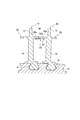
次に、シールド部材30の作用について説明する。図9は、図2のA-A方向の断面図である。図10は、図2のB-B方向の断面図である。
まず、隣接するタービン動翼10のプラットフォーム部20の間の隙間36、38に、シールド部材30を装着する。より詳細には、シールド部材本体側嵌合部32dをプラットフォーム部本体側嵌合溝20dに嵌合し、前縁側シールド部側嵌合部34dを前方スカート側嵌合溝20eに嵌合することにより、シールド部材30を位置決めして装着する。これにより、シールド部材30が、隣接するタービン動翼10のプラットフォーム部20の間の隙間36、38と対向して配置される。
タービン動翼10がタービン軸方向を流れる燃焼ガス流を受けることにより、タービン動翼10は、タービンディスク14と一体的に回転運動をする。この回転運動により、タービン動翼10に遠心力が作用する。この遠心力により、隣接するタービン動翼10のプラットフォーム部20の間の隙間36、38に配置されたシールド部材30が、プラットフォーム部20の内面に接触して密着するので、プラットフォーム部20の間の隙間36、38がシールドされる。
より詳細には、隣接するタービン動翼10におけるプラットフォーム部本体20aの間の隙間36については、プラットフォーム部本体20aの内面に沿って、プラットフォーム部本体20aの内面にシールド部材本体32の第1シールド面32aが接触して密着するので、プラットフォーム部本体20aの間の隙間36がシールドされる。
また、隣接するタービン動翼10における前方スカート20bの間の隙間38については、前方スカート20bの内面に沿って、前方スカート20bの内面に前縁側シールド部34の第2シールド面34aが接触して密着するので、前方スカート20bの間の隙間38がシールドされる。
これにより、燃焼ガスがプラットフォーム部本体20aの間の隙間36や前方スカート20bの間の隙間38から流れ込むことが抑制されるので、タービンディスク14の燃焼ガスによる熱曝露を抑制することが可能となる。
以上、上記構成によれば、隣接するタービン動翼のプラットフォーム部の間の隙間に、セラミックス基複合材料で形成されたシールド部材を配置することにより、隣接するタービン動翼のプラットフォーム部の間の隙間からの燃焼ガスの流れ込みを抑制可能となるので、タービンディスクの熱曝露を抑えることができる。また、シールド部材がセラミックス基複合材料で形成されているので、シールド部材が燃焼ガスに曝露されても熱曝露による損傷を抑えることが可能となる。
上記構成によれば、シャンク部が翼部の形状に対応して湾曲して形成されている場合でも、シールド部材本体は、シャンク部の側面に対応して平面内で湾曲して形成されていることから、シールド部材本体とシャンク部との干渉が抑制され、シールド性能を向上させることが可能となる。
上記構成によれば、シールド部材本体側嵌合部をプラットフォーム部本体側嵌合溝に嵌合し、前縁側シールド部側嵌合部を前方スカート側嵌合溝に嵌合させることにより、隣接するタービン動翼のプラットフォーム部の間に、シールド部材を容易に装着することが可能となると共に、シールド部材を容易に精度よく位置決めして配置することができる。
[第2実施形態]
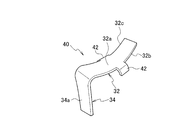
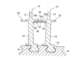
次に、本発明の第2実施形態について図面を用いて詳細に説明する。図11は、第2実施形態のシールド部材40の構成を示す斜視図である。図12は、第2実施形態のシールド部材40をタービン動翼10に装着した状態を示す断面図である。図13は、隣接するタービン動翼10のプラットフォーム部20の間に、第2実施形態のシールド部材40を装着した状態を示す断面図である。なお、図13は、第1実施形態の図9に対応する図であり、図2において第1実施形態のシールド部材30に代えて第2実施形態のシールド部材40を装着した場合におけるA-A方向の断面図である。また、同一の要素には同一の符号を付し、詳細な説明を省略する。
次に、本発明の第2実施形態について図面を用いて詳細に説明する。図11は、第2実施形態のシールド部材40の構成を示す斜視図である。図12は、第2実施形態のシールド部材40をタービン動翼10に装着した状態を示す断面図である。図13は、隣接するタービン動翼10のプラットフォーム部20の間に、第2実施形態のシールド部材40を装着した状態を示す断面図である。なお、図13は、第1実施形態の図9に対応する図であり、図2において第1実施形態のシールド部材30に代えて第2実施形態のシールド部材40を装着した場合におけるA-A方向の断面図である。また、同一の要素には同一の符号を付し、詳細な説明を省略する。
第2実施形態のシールド部材40は、シールド部材本体32の長手方向の両側32b、32cの一部に各々設けられ、シールド部材本体32の長手方向に対して交差する幅方向に突出して形成され、隣接するタービン動翼10におけるシャンク部18の側面に接触し、幅方向の動きを規制する規制部42を有している点において第1実施形態のシールド部材30と相違している。
隣接するタービン動翼10のプラットフォーム部20の間の隙間にシールド部材40を装着した時に、規制部42は、隣接するタービン動翼10の各シャンク部18の側面に面接触または線接触してシールド部材40を保持し、シールド部材40の幅方向の動きを規制する機能を有している。これにより、シールド部材40の幅方向の動きが規制されるので、タービン動翼10の回転運動の初期段階等において、シールド部材40の脱落が抑制されると共に、シールド部材40の位置決め精度が向上する。
規制部42は、シールド部材本体32の長手方向に対して交差する幅方向に突出すると共に、第1シールド面32aの裏面側に向けて湾曲して形成されている。規制部42の形状については、矩形状、三角形状、丸形状等にすることが可能である。
規制部42は、シールド部材本体32の長手方向の同じ位置に設けるようにしてもよく、異なる位置に設けるようにしてもよい。規制部42は、両側縁32b、32cに各々1箇所設けてもよいし、各々複数箇所設けるようにしてもよい。また、規制部42については、一方の側縁32bと他方の側縁32cとにおいて設ける数量が異なるようにしてもよい。規制部42を設ける位置については、シールド部材本体32の長手方向の中央部でもよいし、長手方向の一端側でもよいし、他端側でもよい。
シールド部材40をセラミックス基複合材料で形成する場合には、まず、セラミックス繊維からなる2次元織物や3次元織物をトリムやステッチング等して、シールド部材40の形状に対応したプリフォームを形成する。プリフォームを金型に入れると共に、規制部42に対応する箇所を湾曲させて金型にセットして形成する。セラミックスマトリックスの形成については、第1実施形態のシールド部材30と同様であるので詳細な説明を省略する。
上記構成によれば、第1実施形態のシールド部材の効果を奏すると共に、隣接するタービン動翼のプラットフォーム部の間の隙間にシールド部材を装着した時に、シールド部材本体の規制部が、隣接するタービン動翼の各シャンク部の側面に接触してシールド部材を保持することから、シールド部材の幅方向の動きが規制されるので、シールド部材の脱落が抑制されると共に、シールド部材の位置決め精度が向上する。
[第3実施形態]
次に、本発明の第3実施形態について図面を用いて詳細に説明する。図14は、第3実施形態のシールド部材50の構成を示す斜視図である。図15は、第3実施形態のシールド部材50をタービン動翼10に装着した状態を示す断面図である。なお、同一の要素には同一の符号を付し、詳細な説明を省略する。
次に、本発明の第3実施形態について図面を用いて詳細に説明する。図14は、第3実施形態のシールド部材50の構成を示す斜視図である。図15は、第3実施形態のシールド部材50をタービン動翼10に装着した状態を示す断面図である。なお、同一の要素には同一の符号を付し、詳細な説明を省略する。
プラットフォーム部20の後方スカート20cは、後方スカート20cの内面に設けられ、第3実施形態のシールド部材50におけるシールド部材本体32の長手方向の他端を保持する保持部20fを含んでいる。保持部20fは、後方スカート20cの内面の一部からなり、前縁側に向けて凸状に湾曲した凸曲面の保持面で構成されている。第3実施形態のシールド部材50は、シールド部材本体32の長手方向の他端に設けられ、第1シールド面32aの裏面側に向けて湾曲して形成され、隣接するタービン動翼10の後方スカート20cの保持部20fに接触する湾曲部52を有している点において、第1実施形態のシールド部材30と相違している。
隣接するタービン動翼10のプラットフォーム部20の間の隙間にシールド部材50を装着した時、シールド部材本体32の他端に設けられた湾曲部52が、後方スカート20cの保持部20fである保持面に沿って面接触または線接触することにより、シールド部材本体32が保持される。これにより、シールド部材本体32を保持するためにプラットフォーム部本体20aに設けられたプラットフォーム部本体側嵌合溝20dが不要となるので、プラットフォーム部20の構成がより簡素化されて、タービン動翼10の製造を容易にすることができる。なお、保持部20fについては、凸曲面からなる保持面だけでなく、傾斜平面からなる保持面で構成してもよいし、後方スカートの内面に突起を設けて構成してもよい。
シールド部材50をセラミックス基複合材料で形成する場合には、まず、セラミックス繊維からなる2次元織物や3次元織物をトリムやステッチング等して、シールド部材50の形状に対応したプリフォームを形成する。プリフォームを金型に入れると共に、湾曲部52に対応する箇所を湾曲させて金型にセットして形成する。セラミックスマトリックスの形成については、第1実施形態のシールド部材30と同様であるので詳細な説明を省略する。
上記構成によれば、第1実施形態のシールド部材の効果を奏すると共に、シールド部材本体を保持するためのプラットフォーム部本体に設けられたプラットフォーム部本体側嵌合溝が不要となるので、プラットフォーム部の構成がより簡素化されて、タービン動翼の製造を容易にすることが可能となる。
[第4実施形態]
次に、本発明の第4実施形態について図面を用いて詳細に説明する。図16は、第4実施形態のシールド部材60の構成を示す斜視図である。図17は、第4実施形態のシールド部材60をタービン動翼10に装着した状態を示す断面図である。なお、同一の要素には同一の符号を付し、詳細な説明を省略する。
次に、本発明の第4実施形態について図面を用いて詳細に説明する。図16は、第4実施形態のシールド部材60の構成を示す斜視図である。図17は、第4実施形態のシールド部材60をタービン動翼10に装着した状態を示す断面図である。なお、同一の要素には同一の符号を付し、詳細な説明を省略する。
プラットフォーム部20の後方スカート20cは、後方スカート20cの内面に設けられ、第4実施形態のシールド部材60におけるシールド部材本体32の長手方向の他端を保持する保持部20fを含んでいる。第4実施形態のシールド部材60は、第2実施形態のシールド部材40の規制部42と、第3実施形態のシールド部材50の湾曲部52と、を備えている点において、第1実施形態のシールド部材30と相違している。
シールド部材60をセラミックス基複合材料で形成する場合には、まず、セラミックス繊維からなる2次元織物や3次元織物をトリムやステッチング等して、シールド部材60の形状に対応したプリフォームを形成する。プリフォームを金型に入れると共に、規制部42と湾曲部52とに対応する箇所を湾曲させて金型にセットして形成する。セラミックスマトリックスの形成については、第1実施形態のシールド部材30と同様であるので詳細な説明を省略する。
上記構成によれば、第1実施形態のシールド部材の効果を奏すると共に、第2実施形態のシールド部材と、第3実施形態のシールド部材との効果も奏することが可能となる。
[第5実施形態]
次に、本発明の第5実施形態について図面を用いて詳細に説明する。図18は、第5実施形態のシールド部材70の構成を示す斜視図である。図19は、第5実施形態のシールド部材70をタービン動翼10に装着した状態を示す断面図である。図20は、隣接するタービン動翼10のプラットフォーム部20の間に、第5実施形態のシールド部材70を装着した状態を示す断面図である。図21は、隣接するタービン動翼10のプラットフォーム部20の間に、第5実施形態のシールド部材70を装着した状態を示す断面図である。なお、図20は、第1実施形態の図9に対応する図であり、図2において第1実施形態のシールド部材30に代えて第5実施形態のシールド部材70を装着した場合におけるA-A方向の断面図である。図21は、第1実施形態の図10に対応する図であり、図2において第1実施形態のシールド部材30に代えて第5実施形態のシールド部材70を装着した場合におけるB-B方向の断面図である。また、同一の要素には同一の符号を付し、詳細な説明を省略する。
次に、本発明の第5実施形態について図面を用いて詳細に説明する。図18は、第5実施形態のシールド部材70の構成を示す斜視図である。図19は、第5実施形態のシールド部材70をタービン動翼10に装着した状態を示す断面図である。図20は、隣接するタービン動翼10のプラットフォーム部20の間に、第5実施形態のシールド部材70を装着した状態を示す断面図である。図21は、隣接するタービン動翼10のプラットフォーム部20の間に、第5実施形態のシールド部材70を装着した状態を示す断面図である。なお、図20は、第1実施形態の図9に対応する図であり、図2において第1実施形態のシールド部材30に代えて第5実施形態のシールド部材70を装着した場合におけるA-A方向の断面図である。図21は、第1実施形態の図10に対応する図であり、図2において第1実施形態のシールド部材30に代えて第5実施形態のシールド部材70を装着した場合におけるB-B方向の断面図である。また、同一の要素には同一の符号を付し、詳細な説明を省略する。
プラットフォーム部20の後方スカート20cは、後方スカート20cの内面に設けられ、第5実施形態のシールド部材70におけるシールド部材本体32の長手方向の他端を保持する保持部20fを含んでいる。第5実施形態のシールド部材70は、シールド部材本体32の長手方向の両側の全長に亘って設けられ、シールド部材本体32の長手方向と交差する幅方向に突出すると共に、第1シールド面32aの裏面側へ向けて湾曲して形成され、隣接するタービン動翼10におけるシャンク部18の側面と、後方スカート20cの保持部20fとに接触する第1接触部72を有している。また、シールド部材70は、前縁側シールド部34の長手方向の両側の全長に亘って設けられ、前縁側シールド部34の長手方向と交差する幅方向に突出すると共に、第2シールド面34aの裏面側へ向けて湾曲して形成され、隣接するタービン動翼10におけるシャンク部18の側面に接触する第2接触部74を有している。このように、第5実施形態のシールド部材70は、第1接触部72と、第2接触部74とを有している点において、第1実施形態のシールド部材30と相違している。
隣接するタービン動翼10のプラットフォーム部20の間の隙間36、38にシールド部材70を装着して、シールド部材70を隙間36、38と対向させて配置した時に、シールド部材本体32に設けられた第1接触部72が、隣接するタービン動翼10の各シャンク部18の側面に面接触または線接触し、前縁側シールド部34に設けられた第2接触部74が、隣接するタービン動翼10の各シャンク部18の側面に面接触または線接触してシールド部材70を保持する。これにより、シールド部材70の幅方向の動きが規制されるので、タービン動翼10の回転運動の初期段階等において、シールド部材70の脱落が抑制されると共に、シールド部材70の位置決め精度が向上する。
また、隣接するタービン動翼10のプラットフォーム部20の間の隙間36、38にシールド部材70を装着して、シールド部材70を隙間36、38と対向させて配置した時に、シールド部材本体32に設けられた第1接触部72の後方が、後方スカート20cの保持部20fに接触することにより、シールド部材本体32が保持される。これにより、シールド部材本体32を保持するためにプラットフォーム部本体20aに設けられたプラットフォーム部本体側嵌合溝20dが不要となるので、プラットフォーム部20の構成がより簡素化されて、タービン動翼10の製造を容易にすることができる。
また、シールド部材70では、前縁側シールド部34のダブテール部16側となる他端に、前方スカート20bの内面に設けられた前方スカート側嵌合溝20eと嵌合させるために突出させて形成した前縁側シールド部側嵌合部76が設けられている。
シールド部材70をセラミックス基複合材料で形成する場合には、セラミックス繊維からなる2次元織物や3次元織物をトリムやステッチング等して、シールド部材70の形状に対応したプリフォームを形成する。プリフォームを金型に入れると共に、第1接触部72と第2接触部74とに対応する箇所を湾曲させて金型にセットして形成する。セラミックスマトリックスの形成については、第1実施形態のシールド部材30と同様であるので詳細な説明を省略する。
上記構成によれば、第1実施形態のシールド部材の効果を奏すると共に、隣接するタービン動翼のプラットフォーム部の間の隙間にシールド部材を装着した時に、シールド部材本体に設けられた第1接触部が、隣接するタービン動翼のシャンク部の側面に接触し、前縁側シールド部に設けられた第2接触部が、隣接するタービン動翼のシャンク部の側面に接触してシールド部材を保持する。これにより、シールド部材の幅方向の動きが規制されるので、シールド部材の脱落が抑制されると共に、シールド部材の位置決め精度が向上する。
上記構成によれば、隣接するタービン動翼のプラットフォーム部の間の隙間にシールド部材を装着した時に、シールド部材本体に設けられた第1接触部が、後方スカートの保持部と接触してシールド部材本体を保持することから、プラットフォーム部本体に設けられたプラットフォーム部本体側嵌合溝が不要となるので、タービン動翼の製造を容易にすることが可能となる。
本発明は、隣接するタービン動翼のプラットフォーム部の間の隙間をシールド可能なことから、航空機用ターボファンエンジン等のジェットエンジンに有用なものである。
Claims (9)
- 隣接するタービン動翼のプラットフォーム部の間の隙間に配置され、
セラミックス基複合材料で形成されており、前記プラットフォーム部の間の隙間をシールドする、シールド部材。 - 請求項1に記載のシールド部材であって、
前記プラットフォーム部は、前記タービン動翼の長手方向と交差する方向に延びて形成されているプラットフォーム部本体と、前記プラットフォーム部本体の前縁側に設けられる前方スカートと、を有し、
前記シールド部材は、
細長く形成されており、前記隣接するタービン動翼のプラットフォーム部と接続されたシャンク部の間において、前記隣接するタービン動翼のプラットフォーム部本体の内面に沿って、前記プラットフォーム部本体の内面に接触し、前記プラットフォーム部本体の間の隙間をシールドする第1シールド面を有するシールド部材本体と、
細長く形成されており、前記シールド部材本体の長手方向の一端に、前記シールド部材本体に対して屈曲して長手方向の一端が一体的に設けられ、前記隣接するタービン動翼のシャンク部の間において、前記隣接するタービン動翼の前方スカートの内面に沿って、前記前方スカートの内面に接触し、前記前方スカートの間の隙間をシールドする第2シールド面を有する前縁側シールド部と、
を備える、シールド部材。 - 請求項2に記載のシールド部材であって、
前記シールド部材本体における長手方向の両側の一部に各々設けられ、前記シールド部材本体の長手方向と交差する幅方向に突出すると共に、前記第1シールド面の裏面側に向けて湾曲して形成され、前記隣接するタービン動翼のシャンク部の側面に接触し、前記幅方向の動きを規制する規制部を有している、シールド部材。 - 請求項2または3に記載のシールド部材であって、
前記プラットフォーム部は、前記プラットフォーム部本体の後縁側に設けられる後方スカートを有し、
前記後方スカートは、前記後方スカートの内面に設けられ、前記シールド部材本体の長手方向の他端を保持する保持部を含み、
前記シールド部材は、
前記シールド部材本体の長手方向の他端に設けられ、前記第1シールド面の裏面側に向けて湾曲して形成され、前記隣接するタービン動翼の前記後方スカートの保持部に接触する湾曲部を有している、シールド部材。 - 請求項2に記載のシールド部材であって、
前記プラットフォーム部は、前記プラットフォーム部本体の後縁側に設けられる後方スカートを有し、
前記後方スカートは、前記後方スカートの内面に設けられ、前記シールド部材本体の長手方向の他端を保持する保持部を含み、
前記シールド部材は、
前記シールド部材本体における長手方向の両側の全長に亘って設けられ、前記シールド部材本体の長手方向と交差する幅方向に突出すると共に、前記第1シールド面の裏面側へ向けて湾曲して形成され、前記隣接するタービン動翼におけるシャンク部の側面と、前記後方スカートの保持部とに接触する第1接触部と、
前記前縁側シールド部における長手方向の両側の全長に亘って設けられ、前記前縁側シールド部の長手方向と交差する幅方向に突出すると共に、前記第2シールド面の裏面側へ向けて湾曲して形成され、前記隣接するタービン動翼におけるシャンク部の側面に接触する第2接触部と、
を有する、シールド部材。 - 請求項2から5のいずれか1つに記載のシールド部材であって、
前記シャンク部は、前記タービン動翼の翼部の形状に対応して湾曲して形成されており、
前記シールド部材本体は、前記隣接するタービン動翼のシャンク部の側面に対応して平面内で湾曲して形成されている、シールド部材。 - 請求項2または3に記載のシールド部材であって、
前記プラットフォーム部は、前記プラットフォーム部本体の内面に設けられるプラットフォーム部本体側嵌合溝と、前記前方スカートの内面に設けられる前方スカート側嵌合溝と、を有し、
前記シールド部材本体は、前記シールド部材本体の長手方向の他端に設けられ、前記プラットフォーム部本体側嵌合溝と嵌合するシールド部材本体側嵌合部を有し、
前記前縁側シールド部は、前記前縁側シールド部の長手方向の他端に設けられ、前記前方スカート側嵌合溝と嵌合する前縁側シールド部側嵌合部を有する、シールド部材。 - 請求項4または5に記載のシールド部材であって、
前記プラットフォーム部は、前記前方スカートの内面に設けられる前方スカート側嵌合溝を有しており、
前記前縁側シールド部は、前記前縁側シールド部の長手方向の他端に設けられ、前記前方スカート側嵌合溝と嵌合する前縁側シールド部側嵌合部を有する、シールド部材。 - 請求項1から8のいずれか1つに記載の前記シールド部材を用いるジェットエンジン。
Priority Applications (5)
| Application Number | Priority Date | Filing Date | Title |
|---|---|---|---|
| CA2977064A CA2977064C (en) | 2015-04-07 | 2015-08-21 | Shield member and jet engine using the same |
| CN201580066915.5A CN107109955B (zh) | 2015-04-07 | 2015-08-21 | 密封部件以及使用该密封部件的喷气式发动机 |
| RU2017134792A RU2673963C1 (ru) | 2015-04-07 | 2015-08-21 | Экранирующий элемент и реактивный двигатель, в котором используется такой элемент |
| EP15888531.9A EP3216985B1 (en) | 2015-04-07 | 2015-08-21 | Shield member and jet engine using the same |
| US15/623,954 US10378378B2 (en) | 2015-04-07 | 2017-06-15 | Shield member and jet engine using the same |
Applications Claiming Priority (2)
| Application Number | Priority Date | Filing Date | Title |
|---|---|---|---|
| JP2015078430A JP6554882B2 (ja) | 2015-04-07 | 2015-04-07 | シールド部材及びそれを用いたジェットエンジン |
| JP2015-078430 | 2015-04-07 |
Related Child Applications (1)
| Application Number | Title | Priority Date | Filing Date |
|---|---|---|---|
| US15/623,954 Continuation US10378378B2 (en) | 2015-04-07 | 2017-06-15 | Shield member and jet engine using the same |
Publications (1)
| Publication Number | Publication Date |
|---|---|
| WO2016163040A1 true WO2016163040A1 (ja) | 2016-10-13 |
Family
ID=57072696
Family Applications (1)
| Application Number | Title | Priority Date | Filing Date |
|---|---|---|---|
| PCT/JP2015/073455 Ceased WO2016163040A1 (ja) | 2015-04-07 | 2015-08-21 | シールド部材及びそれを用いたジェットエンジン |
Country Status (7)
| Country | Link |
|---|---|
| US (1) | US10378378B2 (ja) |
| EP (1) | EP3216985B1 (ja) |
| JP (1) | JP6554882B2 (ja) |
| CN (1) | CN107109955B (ja) |
| CA (1) | CA2977064C (ja) |
| RU (1) | RU2673963C1 (ja) |
| WO (1) | WO2016163040A1 (ja) |
Cited By (1)
| Publication number | Priority date | Publication date | Assignee | Title |
|---|---|---|---|---|
| US12546229B1 (en) * | 2024-12-30 | 2026-02-10 | Pratt & Whitney Canada Corp. | Gas turbine engine rotor stage with seal members |
Families Citing this family (9)
| Publication number | Priority date | Publication date | Assignee | Title |
|---|---|---|---|---|
| JP6554882B2 (ja) * | 2015-04-07 | 2019-08-07 | 株式会社Ihi | シールド部材及びそれを用いたジェットエンジン |
| US10358922B2 (en) * | 2016-11-10 | 2019-07-23 | Rolls-Royce Corporation | Turbine wheel with circumferentially-installed inter-blade heat shields |
| US11130170B2 (en) * | 2018-02-02 | 2021-09-28 | General Electric Company | Integrated casting core-shell structure for making cast component with novel cooling hole architecture |
| US11248705B2 (en) * | 2018-06-19 | 2022-02-15 | General Electric Company | Curved seal with relief cuts for adjacent gas turbine components |
| US11047248B2 (en) | 2018-06-19 | 2021-06-29 | General Electric Company | Curved seal for adjacent gas turbine components |
| KR102821442B1 (ko) | 2022-11-23 | 2025-06-16 | 두산에너빌리티 주식회사 | 터빈 베인 플랫폼 씰링 어셈블리, 이를 포함하는 터빈 베인 및 가스 터빈 |
| KR102868006B1 (ko) | 2022-12-09 | 2025-10-01 | 두산에너빌리티 주식회사 | 씰조립체를 구비하는 터빈 베인, 터빈 및 이를 포함하는 터보 머신 |
| KR102791366B1 (ko) | 2022-12-12 | 2025-04-07 | 두산에너빌리티 주식회사 | 터빈 베인 플랫폼 씰링 어셈블리, 이를 포함하는 터빈 베인 및 가스 터빈 |
| US20260049386A1 (en) * | 2024-08-14 | 2026-02-19 | Chromalloy Gas Turbine Llc | Interspacer |
Citations (7)
| Publication number | Priority date | Publication date | Assignee | Title |
|---|---|---|---|---|
| JPH10196309A (ja) * | 1996-12-24 | 1998-07-28 | United Technol Corp <Utc> | タービンブレードプラットホームシール |
| JP2005233251A (ja) * | 2004-02-18 | 2005-09-02 | Eagle Engineering Aerospace Co Ltd | シール装置 |
| JP2006077759A (ja) * | 2004-09-13 | 2006-03-23 | United Technol Corp <Utc> | タービンブレード用ダンパ/シールアセンブリ |
| US20080199307A1 (en) * | 2007-02-15 | 2008-08-21 | Siemens Power Generation, Inc. | Flexible, high-temperature ceramic seal element |
| US20130121810A1 (en) * | 2010-07-27 | 2013-05-16 | Snecma | Inter-blade sealing for a turbine or compressor wheel of a turbine engine |
| WO2014004098A1 (en) * | 2012-06-30 | 2014-01-03 | General Electric Company | A turbine blade sealing structure |
| JP2015135076A (ja) * | 2014-01-17 | 2015-07-27 | 三菱重工業株式会社 | 動翼体のシール構造、動翼体及び回転機械 |
Family Cites Families (16)
| Publication number | Priority date | Publication date | Assignee | Title |
|---|---|---|---|---|
| US2613910A (en) * | 1947-01-24 | 1952-10-14 | Edward A Stalker | Slotted turbine blade |
| JPH07310502A (ja) | 1994-05-19 | 1995-11-28 | Toshiba Corp | タービン動翼 |
| US5785499A (en) | 1996-12-24 | 1998-07-28 | United Technologies Corporation | Turbine blade damper and seal |
| JPH1162502A (ja) * | 1997-08-21 | 1999-03-05 | Ishikawajima Harima Heavy Ind Co Ltd | タービン動翼のシールダンパー |
| JPH1181906A (ja) | 1997-09-04 | 1999-03-26 | Ishikawajima Harima Heavy Ind Co Ltd | タービン動翼のハイブリット緩衝体 |
| JP2001521993A (ja) | 1997-11-03 | 2001-11-13 | シーメンス アクチエンゲゼルシヤフト | 製品、特にセラミックス断熱層を有するガスタービンの構造部材 |
| DE10256778A1 (de) * | 2001-12-11 | 2004-01-08 | Alstom (Switzerland) Ltd. | Schwingungsdämpfer |
| RU2486349C2 (ru) * | 2007-10-25 | 2013-06-27 | Сименс Акциенгезелльшафт | Уплотнительный гребень, узел лопаток турбины и газовая турбина, содержащая такой узел лопаток |
| FR2963382B1 (fr) * | 2010-08-02 | 2016-01-29 | Snecma | Roue de turbine a aubes en composite a matrice ceramique |
| JP2012046398A (ja) | 2010-08-30 | 2012-03-08 | Kyocera Corp | 耐熱性セラミックスおよび断熱材 |
| JP6003660B2 (ja) | 2013-01-11 | 2016-10-05 | 株式会社Ihi | セラミックス基複合部材 |
| US9757920B2 (en) * | 2013-03-15 | 2017-09-12 | Rolls-Royce Corporation | Flexible ceramic matrix composite seal |
| EP2832952A1 (en) | 2013-07-31 | 2015-02-04 | ALSTOM Technology Ltd | Turbine blade and turbine with improved sealing |
| JP6554882B2 (ja) * | 2015-04-07 | 2019-08-07 | 株式会社Ihi | シールド部材及びそれを用いたジェットエンジン |
| US10215028B2 (en) * | 2016-03-07 | 2019-02-26 | Rolls-Royce North American Technologies Inc. | Turbine blade with heat shield |
| US10612385B2 (en) * | 2016-03-07 | 2020-04-07 | Rolls-Royce Corporation | Turbine blade with heat shield |
-
2015
- 2015-04-07 JP JP2015078430A patent/JP6554882B2/ja active Active
- 2015-08-21 EP EP15888531.9A patent/EP3216985B1/en active Active
- 2015-08-21 CN CN201580066915.5A patent/CN107109955B/zh not_active Expired - Fee Related
- 2015-08-21 CA CA2977064A patent/CA2977064C/en active Active
- 2015-08-21 WO PCT/JP2015/073455 patent/WO2016163040A1/ja not_active Ceased
- 2015-08-21 RU RU2017134792A patent/RU2673963C1/ru active
-
2017
- 2017-06-15 US US15/623,954 patent/US10378378B2/en active Active
Patent Citations (7)
| Publication number | Priority date | Publication date | Assignee | Title |
|---|---|---|---|---|
| JPH10196309A (ja) * | 1996-12-24 | 1998-07-28 | United Technol Corp <Utc> | タービンブレードプラットホームシール |
| JP2005233251A (ja) * | 2004-02-18 | 2005-09-02 | Eagle Engineering Aerospace Co Ltd | シール装置 |
| JP2006077759A (ja) * | 2004-09-13 | 2006-03-23 | United Technol Corp <Utc> | タービンブレード用ダンパ/シールアセンブリ |
| US20080199307A1 (en) * | 2007-02-15 | 2008-08-21 | Siemens Power Generation, Inc. | Flexible, high-temperature ceramic seal element |
| US20130121810A1 (en) * | 2010-07-27 | 2013-05-16 | Snecma | Inter-blade sealing for a turbine or compressor wheel of a turbine engine |
| WO2014004098A1 (en) * | 2012-06-30 | 2014-01-03 | General Electric Company | A turbine blade sealing structure |
| JP2015135076A (ja) * | 2014-01-17 | 2015-07-27 | 三菱重工業株式会社 | 動翼体のシール構造、動翼体及び回転機械 |
Non-Patent Citations (1)
| Title |
|---|
| See also references of EP3216985A4 * |
Cited By (1)
| Publication number | Priority date | Publication date | Assignee | Title |
|---|---|---|---|---|
| US12546229B1 (en) * | 2024-12-30 | 2026-02-10 | Pratt & Whitney Canada Corp. | Gas turbine engine rotor stage with seal members |
Also Published As
| Publication number | Publication date |
|---|---|
| CA2977064C (en) | 2018-11-20 |
| US20170284221A1 (en) | 2017-10-05 |
| EP3216985B1 (en) | 2019-04-10 |
| CA2977064A1 (en) | 2016-10-13 |
| US10378378B2 (en) | 2019-08-13 |
| CN107109955B (zh) | 2019-03-26 |
| CN107109955A (zh) | 2017-08-29 |
| RU2673963C1 (ru) | 2018-12-03 |
| JP2016200015A (ja) | 2016-12-01 |
| JP6554882B2 (ja) | 2019-08-07 |
| EP3216985A1 (en) | 2017-09-13 |
| EP3216985A4 (en) | 2018-05-02 |
Similar Documents
| Publication | Publication Date | Title |
|---|---|---|
| JP6554882B2 (ja) | シールド部材及びそれを用いたジェットエンジン | |
| US20150093249A1 (en) | Blade for a gas turbine | |
| US11828199B2 (en) | Methods and assemblies for attaching airfoils within a flow path | |
| US10563523B2 (en) | Method for fabricating a ceramic matrix composite rotor blade | |
| JP6372210B2 (ja) | セラミックス基複合材料よりなるタービン静翼 | |
| CN107636256B (zh) | 涡轮 | |
| EP2800903B1 (en) | Blade track apparatus and method of assembling a blade track apparatus | |
| US10590798B2 (en) | Non-integral blade and platform segment for rotor | |
| US20130011271A1 (en) | Ceramic matrix composite components | |
| JP6763157B2 (ja) | タービンノズル | |
| JP6174839B2 (ja) | セラミックス基複合部材およびその製造方法 | |
| WO2010110325A1 (ja) | Cmcタービン静翼 | |
| US20190226349A1 (en) | Methods and Features for Positioning a Flow Path Inner Boundary Within a Flow Path Assembly | |
| EP3020926A1 (en) | Turbine disk assembly including separable platforms for blade attachment | |
| EP3156614B1 (en) | Gas turbine tip clearance control assembly | |
| US11668317B2 (en) | Airfoil arrangement for a gas turbine engine utilizing a shape memory alloy | |
| CN117597501A (zh) | 包括具有载荷吸收和位置调节的cmc喷嘴的涡轮机涡轮 | |
| CN113966432B (zh) | 具有带载荷传播的cmc喷嘴的涡轮机的涡轮 | |
| EP3789585B1 (en) | Airfoil with metallic shield | |
| US20240229662A9 (en) | Guide vanes assembly with position-maintaining device |
Legal Events
| Date | Code | Title | Description |
|---|---|---|---|
| 121 | Ep: the epo has been informed by wipo that ep was designated in this application |
Ref document number: 15888531 Country of ref document: EP Kind code of ref document: A1 |
|
| REEP | Request for entry into the european phase |
Ref document number: 2015888531 Country of ref document: EP |
|
| ENP | Entry into the national phase |
Ref document number: 2977064 Country of ref document: CA |
|
| WWE | Wipo information: entry into national phase |
Ref document number: 2017134792 Country of ref document: RU |
|
| NENP | Non-entry into the national phase |
Ref country code: DE |