WO2016163263A1 - Objet en nitrure de silicium fritté et élément durable à haute température comprenant celui-ci - Google Patents
Objet en nitrure de silicium fritté et élément durable à haute température comprenant celui-ci Download PDFInfo
- Publication number
- WO2016163263A1 WO2016163263A1 PCT/JP2016/059948 JP2016059948W WO2016163263A1 WO 2016163263 A1 WO2016163263 A1 WO 2016163263A1 JP 2016059948 W JP2016059948 W JP 2016059948W WO 2016163263 A1 WO2016163263 A1 WO 2016163263A1
- Authority
- WO
- WIPO (PCT)
- Prior art keywords
- silicon nitride
- grain boundary
- boundary phase
- sintered body
- nitride sintered
- Prior art date
- Legal status (The legal status is an assumption and is not a legal conclusion. Google has not performed a legal analysis and makes no representation as to the accuracy of the status listed.)
- Ceased
Links
Images


Classifications
-
- C—CHEMISTRY; METALLURGY
- C04—CEMENTS; CONCRETE; ARTIFICIAL STONE; CERAMICS; REFRACTORIES
- C04B—LIME, MAGNESIA; SLAG; CEMENTS; COMPOSITIONS THEREOF, e.g. MORTARS, CONCRETE OR LIKE BUILDING MATERIALS; ARTIFICIAL STONE; CERAMICS; REFRACTORIES; TREATMENT OF NATURAL STONE
- C04B35/00—Shaped ceramic products characterised by their composition; Ceramics compositions; Processing powders of inorganic compounds preparatory to the manufacturing of ceramic products
- C04B35/515—Shaped ceramic products characterised by their composition; Ceramics compositions; Processing powders of inorganic compounds preparatory to the manufacturing of ceramic products based on non-oxide ceramics
- C04B35/58—Shaped ceramic products characterised by their composition; Ceramics compositions; Processing powders of inorganic compounds preparatory to the manufacturing of ceramic products based on non-oxide ceramics based on borides, nitrides, i.e. nitrides, oxynitrides, carbonitrides or oxycarbonitrides or silicides
- C04B35/584—Shaped ceramic products characterised by their composition; Ceramics compositions; Processing powders of inorganic compounds preparatory to the manufacturing of ceramic products based on non-oxide ceramics based on borides, nitrides, i.e. nitrides, oxynitrides, carbonitrides or oxycarbonitrides or silicides based on silicon nitride
-
- B—PERFORMING OPERATIONS; TRANSPORTING
- B23—MACHINE TOOLS; METAL-WORKING NOT OTHERWISE PROVIDED FOR
- B23K—SOLDERING OR UNSOLDERING; WELDING; CLADDING OR PLATING BY SOLDERING OR WELDING; CUTTING BY APPLYING HEAT LOCALLY, e.g. FLAME CUTTING; WORKING BY LASER BEAM
- B23K35/00—Rods, electrodes, materials, or media, for use in soldering, welding, or cutting
- B23K35/22—Rods, electrodes, materials, or media, for use in soldering, welding, or cutting characterised by the composition or nature of the material
- B23K35/36—Selection of non-metallic compositions, e.g. coatings or fluxes; Selection of soldering or welding materials, conjoint with selection of non-metallic compositions, both selections being of interest
- B23K35/3601—Selection of non-metallic compositions, e.g. coatings or fluxes; Selection of soldering or welding materials, conjoint with selection of non-metallic compositions, both selections being of interest with inorganic compounds as principal constituents
-
- C—CHEMISTRY; METALLURGY
- C04—CEMENTS; CONCRETE; ARTIFICIAL STONE; CERAMICS; REFRACTORIES
- C04B—LIME, MAGNESIA; SLAG; CEMENTS; COMPOSITIONS THEREOF, e.g. MORTARS, CONCRETE OR LIKE BUILDING MATERIALS; ARTIFICIAL STONE; CERAMICS; REFRACTORIES; TREATMENT OF NATURAL STONE
- C04B35/00—Shaped ceramic products characterised by their composition; Ceramics compositions; Processing powders of inorganic compounds preparatory to the manufacturing of ceramic products
- C04B35/622—Forming processes; Processing powders of inorganic compounds preparatory to the manufacturing of ceramic products
- C04B35/64—Burning or sintering processes
-
- F—MECHANICAL ENGINEERING; LIGHTING; HEATING; WEAPONS; BLASTING
- F16—ENGINEERING ELEMENTS AND UNITS; GENERAL MEASURES FOR PRODUCING AND MAINTAINING EFFECTIVE FUNCTIONING OF MACHINES OR INSTALLATIONS; THERMAL INSULATION IN GENERAL
- F16C—SHAFTS; FLEXIBLE SHAFTS; ELEMENTS OR CRANKSHAFT MECHANISMS; ROTARY BODIES OTHER THAN GEARING ELEMENTS; BEARINGS
- F16C19/00—Bearings with rolling contact, for exclusively rotary movement
-
- F—MECHANICAL ENGINEERING; LIGHTING; HEATING; WEAPONS; BLASTING
- F16—ENGINEERING ELEMENTS AND UNITS; GENERAL MEASURES FOR PRODUCING AND MAINTAINING EFFECTIVE FUNCTIONING OF MACHINES OR INSTALLATIONS; THERMAL INSULATION IN GENERAL
- F16C—SHAFTS; FLEXIBLE SHAFTS; ELEMENTS OR CRANKSHAFT MECHANISMS; ROTARY BODIES OTHER THAN GEARING ELEMENTS; BEARINGS
- F16C33/00—Parts of bearings; Special methods for making bearings or parts thereof
- F16C33/30—Parts of ball or roller bearings
- F16C33/32—Balls
-
- F—MECHANICAL ENGINEERING; LIGHTING; HEATING; WEAPONS; BLASTING
- F16—ENGINEERING ELEMENTS AND UNITS; GENERAL MEASURES FOR PRODUCING AND MAINTAINING EFFECTIVE FUNCTIONING OF MACHINES OR INSTALLATIONS; THERMAL INSULATION IN GENERAL
- F16C—SHAFTS; FLEXIBLE SHAFTS; ELEMENTS OR CRANKSHAFT MECHANISMS; ROTARY BODIES OTHER THAN GEARING ELEMENTS; BEARINGS
- F16C2202/00—Solid materials defined by their properties
- F16C2202/20—Thermal properties
Definitions
- Embodiment described later relates to a silicon nitride sintered body and a high temperature durability member using the same.
- Silicon nitride sintered bodies are used in various applications such as bearing balls, rolling rolls, friction stir welding tools, hot tools, heater substrates, semiconductor substrates, and cutting tools.
- Japanese Patent No. 5268750 discloses a silicon nitride sintered body in which the number of silicon nitride crystal particles having a major axis of 3 ⁇ m or more per unit area of 10 ⁇ m ⁇ 10 ⁇ m is controlled. In Patent Document 1, Vickers hardness and wear resistance are improved by performing such control.
- Patent Laying-Open No. 2010-194591 Patent Document 2 discloses a silicon nitride sintered body constituting a friction stir welding tool.
- a coating layer is provided on the tool surface in order to improve the durability of the joining tool.
- Friction stir welding is a method in which a welding tool (joining tool) is pressed against a member to be joined while rotating at high speed, and the members to be joined are joined using frictional heat. Since the frictional heat is used, the joining tool becomes a high temperature of 300 ° C. or higher.
- a coating layer is provided in order to provide durability at high temperatures.
- the silicon nitride sintered body is used for various applications as described above. For example, the sliding surface of the bearing ball becomes hot as the rotational speed increases. Similarly, with friction stir welding tools, the sliding surface becomes hot due to frictional heat.
- the use environment of a rolling roll, a hot tool, and a cutting tool may become under high temperature.
- the present invention has been made to cope with such a problem, and an object of the present invention is to provide a silicon nitride sintered body exhibiting excellent durability even in a high temperature environment.
- the silicon nitride sintered body according to the embodiment is a silicon nitride sintered body having silicon nitride crystal particles and a grain boundary phase.
- the silicon nitride crystal particles are covered with the grain boundary phase, and the width of the grain boundary phase is 0. .2 nm or more.
- the width of the grain boundary phase is preferably 0.2 nm or more and 5 nm or less.
- the silicon nitride sintered body is manufactured by mixing silicon nitride powder and sintering aid powder, forming and then sintering. By carrying out the sintering step, the sintering aid powder becomes a grain boundary phase.
- the silicon nitride sintered body according to the embodiment is characterized in that the width of the grain boundary phase is 0.2 nm or more.
- the width of the grain boundary phase is the thickness of the grain boundary phase formed at the two-grain interface of the silicon nitride crystal grains.
- the presence of a grain boundary phase having a predetermined thickness at the interface between two silicon nitride crystal grains indicates that the surface of each silicon nitride crystal grain is covered with the grain boundary phase.
- the nearest distance between adjacent silicon nitride crystal grains is preferably 0.2 nm or more, and more preferably in the range of 0.2 to 5 nm.
- silicon nitride crystal particles present on the surface of the silicon nitride sintered body may not be covered with the grain boundary phase.
- all silicon nitride crystal particles are covered with the grain boundary phase.
- the durability of the silicon nitride sintered body in a high temperature environment is improved.
- the fact that the silicon nitride crystal particles are not covered with the grain boundary phase indicates a state where the silicon nitride crystal particles are in direct contact with each other and a state where the grain boundary phase is missing and becomes a pore.
- the width of the grain boundary phase is set to 0.2 nm or more, the silicon nitride crystal particles can be firmly bonded via the grain boundary phase. If the width of the grain boundary phase is less than 0.2 nm, a strong joint structure cannot be obtained.
- the width of the grain boundary phase is preferably in the range of 0.2 to 5 nm, more preferably 0.5 to 2 nm.
- the width of the grain boundary phase is measured by a method using a scanning transmission electron microscope (STEM). Specifically, an arbitrary cross section of the silicon nitride sintered body is observed by STEM (enlarged photograph is taken). Next, the intensity profile of the grain boundary portion at the closest location between the two silicon nitride crystal grains is obtained by an enlarged photograph. Thereby, the width of the grain boundary phase can be measured.
- STEM scanning transmission electron microscope
- the width of the grain boundary phase between two silicon nitride crystal particles is 0.2 nm or more.
- the shortest distance between two silicon nitride crystal particles is 0.2 nm or more.
- the fact that the width of the grain boundary phase is 0.2 to 5 nm indicates that the shortest distance between two silicon nitride crystal grains is in the range of 0.2 to 5 nm.
- the silicon nitride sintered body according to the embodiment preferably has a Vickers hardness Hv of 1450 or more at room temperature (25 ° C.). Moreover, it is preferable that Vickers hardness Hv in 300 degreeC is 1350 or more. Moreover, it is preferable that Vickers hardness Hv in 1000 degreeC is 850 or more. Since the silicon nitride sintered body according to the embodiment controls the width of the grain boundary phase, high hardness can be maintained even if the usage environment is a high temperature condition of 300 ° C. or higher. The measurement of Vickers hardness is performed based on JIS-R-1610. The test force is assumed to be 9.807N.
- the silicon nitride sintered body preferably contains 15% by mass or less of a grain boundary phase as an additive component.
- the additive component refers to a component other than silicon nitride.
- additive components other than silicon nitride indicate a sintering aid component.
- the sintering aid component constitutes the grain boundary phase. When there are many additional components exceeding 15 mass%, a grain boundary phase will increase too much. When the grain boundary phase is excessive, it becomes difficult to control the width of the grain boundary phase within the range of 0.2 to 5 nm.
- the silicon nitride sintered body of the present embodiment has a structure in which elongated ⁇ -silicon nitride crystal particles are entangled in a complicated manner.
- the sintering aid component is a chemical, it is not desirable because the silicon nitride crystal particles may have a part that cannot take a complicated structure.
- the additive component is preferably 3% by mass or more and 12.5% by mass or less. Furthermore, 5 mass% or more and 12.5 mass% or less of an additional component are preferable. If the additive component is less than 3% by mass, the grain boundary phase becomes too small and the density of the silicon nitride sintered body may be lowered.
- the additive component includes three or more elements selected from Y, Al, Mg, Si, Ti, Hf, Mo, and C.
- the additive components include Y (yttrium), Al (aluminum), Mg (magnesium), Si (silicon), Ti (titanium), Hf (hafnium), Mo (molybdenum), and C (carbon) as constituent elements.
- the compound form is not limited.
- oxide (including composite oxide), nitride (including composite nitride), oxynitride (including composite oxynitride), carbide (including composite carbide), and the like can be given.
- oxide including composite oxide
- nitride including composite nitride
- carbide including composite carbide
- oxide including composite oxide
- Y element yttrium oxide
- Al element aluminum oxide (Al 2 O 3 ), aluminum nitride (AlN), and MgO ⁇ Al 2 O 3 spinel are preferable.
- Mg element magnesium oxide (MgO) and MgO.Al 2 O 3 spinel are preferable.
- Si element silicon oxide (SiO 2 ) and silicon carbide (SiC) are preferable.
- Ti element titanium oxide (TiO 2 ) and titanium nitride (TiN) are preferable.
- Hf element hafnium oxide (HfO 2 ) is preferable.
- Mo element molybdenum oxide (MoO 2 ) and molybdenum carbide (Mo 2 C) are preferable.
- C element it is preferable to add as silicon carbide (SiC), titanium carbide (TiC), and titanium carbonitride (TiCN).
- SiC silicon carbide
- TiC titanium carbide
- TiCN titanium carbonitride
- the additive component preferably includes four or more elements selected from Y, Al, Mg, Si, Ti, Hf, Mo, and C.
- the sinterability is improved and silicon nitride is improved.
- the coarsening of the crystal grains can be prevented, and a crystal structure in which the ⁇ -silicon nitride crystal grains are entangled in a complicated manner can be formed.
- a solid solution or a crystalline compound can be formed in the grain boundary phase.
- the presence or absence of a crystalline compound can be analyzed by XRD (X-ray diffraction method).
- XRD X-ray diffraction method
- the XRD analysis conditions are a Cu target (CuK ⁇ ), a tube voltage of 40 kV, a tube current of 40 mA, and a slit diameter of 0.2 mm.
- the scanning range (2 ⁇ ) is 20 to 60 °. If a peak other than the peak based on silicon nitride appears in this range, it can be confirmed that a crystalline compound is present in the grain boundary phase.
- the width of the grain boundary phase between two particles is 0.2 nm or more, and further 0.2 to 5 nm, a fine crystalline compound can be interposed at the interface between the two particles. Thereby, durability at the high temperature of a sintered compact can further be improved. Further, as a combination of sintering aids added in the production process, the following combinations are preferable.
- MgO is 0.1 to 1.7% by mass
- Al 2 O 3 is 0.1 to 4.3% by mass
- SiC is 0.1 to 10% by mass
- SiO 2 is 0%. 1 to 2% by mass is added.
- four elements of Mg, Al, Si, and C are contained as additives.
- MgO ⁇ Al 2 O 3 may be added 0.2-6% by weight as a spinel.
- TiO 2 may be added to the first combination.
- Y 2 O 3 is 0.2 to 3% by mass
- MgO ⁇ Al 2 O 3 spinel is 0.5 to 5% by mass
- AlN is 2 to 6% by mass
- HfO 2 to 0.5 to 3% by mass
- Mo 2 C to 0.1 to 3% by mass
- the additive component elements are three types, Y, Al, and Hf.
- the upper limit of the content of the sintering aid component is 15% by mass or less in total. None of the first to third combinations uses a combination in which Y 2 O 3 and Al 2 O 3 are added. The first combination does not use Y 2 O 3 . The second combination is added as MgO ⁇ Al 2 O 3 spinel. The third combination does not use Al 2 O 3 .
- yttrium aluminum oxides such as YAG (Al 5 Y 3 O 12 ), YAM (Al 2 Y 4 O 9 ), and YAL (AlYO 3 ) are formed. It is easy to be done.
- the first to third combinations are easy to form a crystalline compound. In addition, crystalline compounds other than YAG, YAM, and YAL can be formed. In other words, when a crystalline compound other than YAG, YAM, and YAL is contained, durability at a high temperature can be improved.
- the additive component also has an excellent role as a sintering aid. Therefore, the ratio of ⁇ -type silicon nitride crystal particles having an aspect ratio of 2 or more can be increased to 60% or more.
- the ratio of the aspect ratio of 2 or more is that the SEM observation of an arbitrary cross section of the silicon nitride sintered body is taken to take an enlarged photograph (3000 times or more), and the major axis and minor axis of the silicon nitride crystal particles appearing in the enlarged photograph are determined. Measure and determine the aspect ratio.
- the area ratio (%) of silicon nitride crystal grains having an aspect ratio of 2 or more per unit area of 50 ⁇ m ⁇ 50 ⁇ m is obtained.
- the number ratio of silicon nitride particles having a particle diameter of 2 ⁇ m or more to the entire silicon nitride particles is set to a high value of 35% or more. I can do it.
- the upper limit of the number ratio is preferably 55% or less. If the particles are excessively large, it is difficult to control the width of the grain boundary phase.
- the silicon nitride sintered body as described above not only the aforementioned Vickers hardness but also the fracture toughness value and the three-point bending strength can be improved.
- the fracture toughness value is 6.0 MPa ⁇ m 1/2 or more, and the three-point bending strength can be 900 MPa or more.
- the fracture toughness value is a value obtained by Niihara's formula based on the IF method of JIS-R-1607.
- the three-point bending strength is a value based on JIS-R1601.
- the silicon nitride sintered body as described above is suitable as a constituent material of the high temperature durability member. Since the silicon nitride sintered body according to the embodiment has a high Vickers hardness under a high temperature environment, the silicon nitride sintered body is suitable as a constituent material of a high temperature durability member whose use environment is 300 ° C. or higher. Examples of such fields of use include any one of bearing balls, rolling rolls, friction stir welding tools, hot tools, and heaters.
- Figure 1 shows an example of a bearing ball.
- reference numeral 1 is a bearing ball
- 2 is a friction surface. Since the bearing ball 1 is a sphere, the entire sphere surface functions as the friction surface 2.
- the constituent material of the bearing ball 1 is a silicon nitride sintered body. Since durability at high temperatures is improved, it can be applied to bearings used in high temperature environments. Further, even when the frictional heat becomes high with high-speed rotation, excellent durability can be obtained.
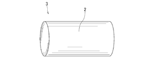
- FIG. 2 shows an example of the rolling roll comprised with the silicon nitride sintered compact of this embodiment.
- reference numeral 3 is a rolling roll
- 2 is a friction surface (rolling surface).
- the rolling roll has a cylindrical shape.
- the cylindrical roll surface is the friction surface 2.
- the rolling roll is applied to various usage environments such as room temperature processing and hot processing.
- the friction surface 2 is comprised from a silicon nitride sintered compact. Since the durability of the silicon nitride sintered body at a high temperature is improved, it can be applied to a hot-rolling roll at 300 ° C. or higher.
- FIG. 3 shows an example of a friction stir welding tool composed of the silicon nitride sintered body of the present embodiment.
- reference numeral 4 is a friction stir welding tool
- 2 is a friction surface.
- the friction surface 2 of the friction stir welding tool 4 is composed of a silicon nitride sintered body.
- FIG. 3 illustrates a cylindrical joining tool, it can also be applied to a joining tool such as a sphere or a convex shape.
- the friction stir welding apparatus is preferably used with the rotational speed of the welding tool member set to 500 rpm or more and the indentation load set to 5 kN or more in order to shorten the joining time of the materials to be joined and increase the production efficiency. It is.
- the friction surface may be in a high temperature environment where the temperature of the friction surface is 800 ° C. or higher. Even in that case, since the durability of the silicon nitride sintered body at a high temperature is improved, the durability as a bonding tool is improved. In addition to the above-mentioned fields of use, it is also suitable as a constituent material for high-temperature durable members whose operating environment is 300 ° C. or higher, such as hot tools and heater substrates.
- the surface roughness Ra of the friction surface 2 is preferably 5 ⁇ m or less. By reducing the surface roughness Ra of the friction surface, it is possible to improve the wear resistance and sliding characteristics of the sliding member such as a bearing ball and a friction stir welding tool.
- the silicon nitride sintered body according to the embodiment has the above-described configuration, its manufacturing method is not particularly limited, but the following method can be given as a method for obtaining it efficiently.
- preparation of the raw material powder is important.
- the silicon nitride powder one having an average particle size of 2 ⁇ m or less, an alpha conversion rate of 90% or more, and an impurity oxygen content of 2 wt% or less is prepared.
- the sintering aid powder As a first method, it is preferable to make the sintering aid powder to be added finer with an average particle diameter of 1 ⁇ m or less, and further 0.5 ⁇ m or less.
- the standard deviation of the average particle size of the sintering aid powder is preferably 0.2 ⁇ m or less.
- a method such as miniaturization or sieving by a ball mill or a jet mill.
- Such a sintering aid powder and silicon nitride powder are mixed to prepare a raw material powder.
- the sintering aid becomes a grain boundary phase in the sintering process.
- a thin grain boundary phase can be formed by using a small sintering aid powder having a uniform particle size.
- the relationship of 0.8A ⁇ B is preferably satisfied.
- a sintering aid powder having a particle size smaller than that of silicon nitride powder By mixing a sintering aid powder having a particle size smaller than that of silicon nitride powder, a thin grain boundary phase can be easily formed. Therefore, it is more preferable that 0.7A ⁇ B.
- the lower limit of the ratio of the average particle diameter is not particularly limited, but is preferably in the range of 0.8A ⁇ B ⁇ 0.2A. If the average particle size B ⁇ m of the sintering aid powder is too small than the average particle size A ⁇ m of the silicon nitride powder, it becomes difficult to adjust.
- a granulated powder is obtained by granulating a mixed powder obtained by adding an organic binder to the raw material powder prepared by the first method (a mixture of silicon nitride powder and sintering aid powder). It is to carry out the manufacturing process.
- a mixed powder obtained by adding an organic binder to the raw material powder prepared by the first method (a mixture of silicon nitride powder and sintering aid powder). It is to carry out the manufacturing process.
- the granulated powder in advance, it is possible to realize a state in which the sintering aid powder is uniformly present around the silicon nitride powder. Thereby, a predetermined thin grain boundary phase can be formed.
- a step of filling the mold with granulated powder and molding it is performed.
- the molding process it is preferable to use a mold having a target probe shape.
- mold molding, CIP (cold isostatic pressing method), or the like may be used.
- the molded body obtained in the molding process is degreased.
- the degreasing step is preferably performed at a temperature of 400 to 800 ° C. in nitrogen.
- a heat treatment is performed on the degreased body produced by the second method.
- the particle surface can be activated.
- the heat treatment temperature is preferably in the range of 300 to 900 ° C.
- the heat treatment is preferably performed in vacuum, in an inert atmosphere, or in the air.
- the heat treatment temperature exceeds 900 ° C., it becomes difficult to obtain a dense sintered body in the sintering step.
- the heat treatment time is preferably in the range of 2 to 10 hours.
- the heat-treated body obtained by the third method is sintered.
- the sintering process is performed at a temperature of 1600 ° C. or higher.
- the sintering step is preferably performed in an inert atmosphere or in a vacuum. Examples of the inert atmosphere include a nitrogen atmosphere and an argon atmosphere. Examples of the sintering step include atmospheric pressure sintering, pressure sintering, hot isostatic pressing (HIP), and discharge plasma sintering (SPS).
- a plurality of types of sintering methods may be combined.
- a portion corresponding to the friction surface is polished on the obtained sintered body.
- the polishing process is preferably a polishing process using a diamond grindstone.
- Example 2 As the silicon nitride powder, an ⁇ -type silicon nitride powder having an average particle diameter of 1 ⁇ m ( ⁇ conversion rate: 98%) was prepared. Next, samples 1 to 6 shown in Table 1 were prepared as sintering aid powders. While the sintering aid powder was pulverized by a ball mill, its average particle size and standard deviation were measured using a wet particle size distribution measuring machine.
- a granulated powder was prepared by mixing a silicon nitride powder and 2% by mass of an organic binder with the sintering aid powders of Samples 1 to 6, and molding was performed.
- the obtained molded body was subjected to a degreasing treatment, and the heat treatment shown in Table 2 was performed on the obtained degreased body.
- the heat-treated body and the degreased body manufactured in the steps of Table 2 were subjected to normal pressure sintering at a temperature of 1800-1900 ° C. for 5-10 hours. Further, the sintered bodies of Examples 1 to 6 and Comparative Examples 1 and 2 were subjected to HIP treatment at a temperature of 1700 to 1900 ° C. By this sintering / HIP treatment step, a silicon nitride sintered body having a length of 50 mm, a width of 50 mm and a thickness of 6 mm was produced. The surface roughness Ra was adjusted to 1 ⁇ m. With respect to the obtained sintered body, three-point bending strength, fracture toughness value and Vickers hardness were measured.
- the Vickers hardness Hv was measured with a test force of 9.807 N (Newton) based on JIS-R-1610. Further, the fracture toughness value is a value obtained by Niihara's formula in accordance with the IF method of JIS-R-1607. The three-point bending strength was measured in accordance with JIS-R-1601. All were measured at room temperature (25 ° C.). The measurement results are shown in Table 3 below.
- the average particle diameter and the width of the grain boundary phase of the silicon nitride crystal particles of the silicon nitride sintered bodies according to the respective examples and comparative examples were measured by the following procedure. Moreover, the presence or absence of formation of a solid solution or a crystalline compound in the grain boundary phase was observed.
- the width of the grain boundary phase was measured by STEM (scanning transmission electron microscope). Specifically, first, an arbitrary cross section of the silicon nitride sintered body is observed by STEM (enlarged photograph is taken). Next, in the obtained enlarged photograph, the intensity profile of the grain boundary part at the closest point between the two silicon nitride crystal grains was obtained, and the width of the grain boundary phase was measured. The presence or absence of a solid solution or a crystalline compound in the grain boundary phase was confirmed by XRD (X-ray diffraction method). The results are shown in Table 4 below.
- the average particle size of the silicon nitride crystal particles of the sintered bodies according to the respective examples was in the range of 1.4 to 2.1 ⁇ m, and no significant difference was observed.
- the width of the grain boundary phase was 70 to 100 nm in the comparative example, whereas the width of the grain boundary phase of the sintered body according to each example was in the range of 0.2 to 5 nm.
- crystalline compounds other than YAG, YAM, and YAL were detected in the grain boundary phases of the sintered bodies according to the respective examples.
- Vickers hardness under high temperature conditions was measured for the silicon nitride sintered bodies according to the examples and comparative examples. Vickers hardness Hv was measured by changing the measurement environment to 300 ° C, 800 ° C, 1000 ° C, and 1200 ° C. Measurement was carried out by holding at each temperature for 1 hour. The results are shown in Table 5 below.
- the silicon nitride sintered body according to each example had a high Vickers hardness under a high temperature environment. This is because since a thin grain boundary phase is formed, the grain boundary phase hardly deteriorates in a high temperature environment. As described above, the silicon nitride sintered body according to each example exhibits excellent hardness even in a high temperature environment, and thus it has been found that the silicon nitride sintered body is suitable as a constituent material of a high temperature durability member having an operating environment of 300 ° C. or higher.
Landscapes
- Engineering & Computer Science (AREA)
- Chemical & Material Sciences (AREA)
- Ceramic Engineering (AREA)
- General Engineering & Computer Science (AREA)
- Mechanical Engineering (AREA)
- Manufacturing & Machinery (AREA)
- Structural Engineering (AREA)
- Organic Chemistry (AREA)
- Materials Engineering (AREA)
- Inorganic Chemistry (AREA)
- Ceramic Products (AREA)
- Rolls And Other Rotary Bodies (AREA)
- Rolling Contact Bearings (AREA)
Abstract
Priority Applications (4)
| Application Number | Priority Date | Filing Date | Title |
|---|---|---|---|
| CN201680019713.XA CN107531579B (zh) | 2015-04-07 | 2016-03-28 | 氮化硅烧结体及使用其的高温耐久性构件 |
| JP2017510938A JP6677714B2 (ja) | 2015-04-07 | 2016-03-28 | 窒化珪素焼結体およびそれを用いた高温耐久性部材 |
| US15/564,320 US10787393B2 (en) | 2015-04-07 | 2016-03-28 | Silicon nitride sintered body and high-temperature-resistant member using the same |
| EP16776431.5A EP3281927B1 (fr) | 2015-04-07 | 2016-03-28 | Objet en nitrure de silicium fritté et élément durable à haute température comprenant celui-ci |
Applications Claiming Priority (4)
| Application Number | Priority Date | Filing Date | Title |
|---|---|---|---|
| JP2015-078571 | 2015-04-07 | ||
| JP2015078571 | 2015-04-07 | ||
| JP2015-124901 | 2015-06-22 | ||
| JP2015124901 | 2015-06-22 |
Publications (1)
| Publication Number | Publication Date |
|---|---|
| WO2016163263A1 true WO2016163263A1 (fr) | 2016-10-13 |
Family
ID=57071868
Family Applications (1)
| Application Number | Title | Priority Date | Filing Date |
|---|---|---|---|
| PCT/JP2016/059948 Ceased WO2016163263A1 (fr) | 2015-04-07 | 2016-03-28 | Objet en nitrure de silicium fritté et élément durable à haute température comprenant celui-ci |
Country Status (5)
| Country | Link |
|---|---|
| US (1) | US10787393B2 (fr) |
| EP (1) | EP3281927B1 (fr) |
| JP (1) | JP6677714B2 (fr) |
| CN (1) | CN107531579B (fr) |
| WO (1) | WO2016163263A1 (fr) |
Cited By (5)
| Publication number | Priority date | Publication date | Assignee | Title |
|---|---|---|---|---|
| CN111153700A (zh) * | 2019-12-31 | 2020-05-15 | 欧钛鑫光电科技(苏州)有限公司 | 一种氮化物靶材的制备方法 |
| JPWO2021241583A1 (fr) * | 2020-05-26 | 2021-12-02 | ||
| WO2023171510A1 (fr) * | 2022-03-10 | 2023-09-14 | デンカ株式会社 | Corps fritté en céramique ainsi que procédé de fabrication de celui-ci, et poudre d'auxiliaire de frittage |
| WO2023171511A1 (fr) * | 2022-03-10 | 2023-09-14 | デンカ株式会社 | Corps fritté en céramique ainsi que procédé de fabrication de celui-ci, et poudre d'auxiliaire de frittage |
| WO2024111483A1 (fr) * | 2022-11-25 | 2024-05-30 | デンカ株式会社 | Corps fritté en céramique ainsi que procédé de fabrication de celui-ci, corps lié, et module de puissance |
Families Citing this family (4)
| Publication number | Priority date | Publication date | Assignee | Title |
|---|---|---|---|---|
| JP7402177B2 (ja) * | 2018-12-11 | 2023-12-20 | 株式会社東芝 | 摺動部材、およびそれを用いた軸受、モータ、並びに駆動装置 |
| CN111606717A (zh) * | 2020-06-08 | 2020-09-01 | 浙江锐克特种陶瓷有限公司 | 一种高强高硬氮化硅耐磨片的制备方法 |
| CN115715278A (zh) * | 2020-06-30 | 2023-02-24 | 株式会社德山 | 氮化硅烧结体的连续制造方法 |
| CN117083256B (zh) * | 2022-03-16 | 2025-03-04 | 株式会社东芝 | 氮化硅烧结体及使用了其的耐磨性构件 |
Citations (3)
| Publication number | Priority date | Publication date | Assignee | Title |
|---|---|---|---|---|
| JPH07180738A (ja) * | 1993-12-24 | 1995-07-18 | Kyocera Corp | セラミック弾性部材 |
| WO2011102298A1 (fr) * | 2010-02-16 | 2011-08-25 | 株式会社東芝 | Élément résistant à l'usure et son procédé de fabrication |
| WO2013035302A1 (fr) * | 2011-09-05 | 2013-03-14 | 株式会社 東芝 | Corps fritté de nitrure de silicium, son procédé de fabrication et élément résistant à l'abrasion et palier fabriqués chacun à l'aide de celui-ci |
Family Cites Families (6)
| Publication number | Priority date | Publication date | Assignee | Title |
|---|---|---|---|---|
| JP3114302B2 (ja) * | 1990-11-30 | 2000-12-04 | トヨタ自動車株式会社 | 窒化珪素焼結体及びその製造方法 |
| JP2002029851A (ja) * | 2000-07-17 | 2002-01-29 | Denki Kagaku Kogyo Kk | 窒化珪素質組成物、それを用いた窒化珪素質焼結体の製造方法と窒化珪素質焼結体 |
| JP4795588B2 (ja) | 2001-01-12 | 2011-10-19 | 株式会社東芝 | 窒化けい素製耐摩耗性部材 |
| US8377837B2 (en) * | 2008-04-18 | 2013-02-19 | Kabushiki Kaisha Toshiba | Wear resistant member, wear resistant device and method for manufacturing the wear resistant member |
| JP2010194591A (ja) | 2009-02-26 | 2010-09-09 | Kyocera Corp | 摩擦攪拌接合用工具および摩擦攪拌接合装置 |
| JP5268750B2 (ja) | 2009-04-01 | 2013-08-21 | 株式会社東芝 | 耐衝撃部材およびその製造方法 |
-
2016
- 2016-03-28 WO PCT/JP2016/059948 patent/WO2016163263A1/fr not_active Ceased
- 2016-03-28 EP EP16776431.5A patent/EP3281927B1/fr active Active
- 2016-03-28 CN CN201680019713.XA patent/CN107531579B/zh active Active
- 2016-03-28 US US15/564,320 patent/US10787393B2/en active Active
- 2016-03-28 JP JP2017510938A patent/JP6677714B2/ja active Active
Patent Citations (3)
| Publication number | Priority date | Publication date | Assignee | Title |
|---|---|---|---|---|
| JPH07180738A (ja) * | 1993-12-24 | 1995-07-18 | Kyocera Corp | セラミック弾性部材 |
| WO2011102298A1 (fr) * | 2010-02-16 | 2011-08-25 | 株式会社東芝 | Élément résistant à l'usure et son procédé de fabrication |
| WO2013035302A1 (fr) * | 2011-09-05 | 2013-03-14 | 株式会社 東芝 | Corps fritté de nitrure de silicium, son procédé de fabrication et élément résistant à l'abrasion et palier fabriqués chacun à l'aide de celui-ci |
Non-Patent Citations (3)
| Title |
|---|
| CINIBULK, MICHAEL K. ET AL.: "Quantitative Comparison of TEM Techniques for Determining Amorphous Intergranular Film Thickness", JOURNAL OF THE AMERICAN CERAMIC SOCIETY, vol. 76, no. 2, 1993, pages 426 - 432, XP055320285, ISSN: 0002-7820 * |
| KLEEBE, HANS-JOACHIM ET AL.: "Statistical Analysis of the Intergranular Film Thickness in Silicon Nitride Ceramics", JOURNAL OF THE AMERICAN CERAMIC SOCIETY, vol. 76, no. 8, 1993, pages 1969 - 1977, XP055320288, ISSN: 0002-7820 * |
| See also references of EP3281927A4 * |
Cited By (12)
| Publication number | Priority date | Publication date | Assignee | Title |
|---|---|---|---|---|
| CN111153700A (zh) * | 2019-12-31 | 2020-05-15 | 欧钛鑫光电科技(苏州)有限公司 | 一种氮化物靶材的制备方法 |
| JPWO2021241583A1 (fr) * | 2020-05-26 | 2021-12-02 | ||
| JP2024101045A (ja) * | 2020-05-26 | 2024-07-26 | 株式会社東芝 | 窒化珪素焼結体、それを用いた耐摩耗性部材、および窒化珪素焼結体の製造方法 |
| JP7528209B2 (ja) | 2020-05-26 | 2024-08-05 | 株式会社東芝 | 窒化珪素焼結体、それを用いた耐摩耗性部材、および窒化珪素焼結体の製造方法 |
| JP7790852B2 (ja) | 2020-05-26 | 2025-12-23 | 株式会社Niterra Materials | 窒化珪素焼結体、それを用いた耐摩耗性部材、および窒化珪素焼結体の製造方法 |
| WO2023171510A1 (fr) * | 2022-03-10 | 2023-09-14 | デンカ株式会社 | Corps fritté en céramique ainsi que procédé de fabrication de celui-ci, et poudre d'auxiliaire de frittage |
| WO2023171511A1 (fr) * | 2022-03-10 | 2023-09-14 | デンカ株式会社 | Corps fritté en céramique ainsi que procédé de fabrication de celui-ci, et poudre d'auxiliaire de frittage |
| JP7401718B1 (ja) * | 2022-03-10 | 2023-12-19 | デンカ株式会社 | 窒化ケイ素焼結体及び焼結助剤粉末 |
| JP7408884B1 (ja) * | 2022-03-10 | 2024-01-05 | デンカ株式会社 | 窒化ケイ素焼結体及び焼結助剤粉末 |
| WO2024111483A1 (fr) * | 2022-11-25 | 2024-05-30 | デンカ株式会社 | Corps fritté en céramique ainsi que procédé de fabrication de celui-ci, corps lié, et module de puissance |
| JPWO2024111483A1 (fr) * | 2022-11-25 | 2024-05-30 | ||
| JP7576209B2 (ja) | 2022-11-25 | 2024-10-30 | デンカ株式会社 | 窒化ケイ素焼結体及びその製造方法、接合体、並びに、パワーモジュール |
Also Published As
| Publication number | Publication date |
|---|---|
| JPWO2016163263A1 (ja) | 2018-03-22 |
| JP6677714B2 (ja) | 2020-04-08 |
| US10787393B2 (en) | 2020-09-29 |
| CN107531579B (zh) | 2020-10-23 |
| EP3281927A1 (fr) | 2018-02-14 |
| EP3281927A4 (fr) | 2018-12-05 |
| CN107531579A (zh) | 2018-01-02 |
| US20180134626A1 (en) | 2018-05-17 |
| EP3281927B1 (fr) | 2020-02-19 |
Similar Documents
| Publication | Publication Date | Title |
|---|---|---|
| JP6677714B2 (ja) | 窒化珪素焼結体およびそれを用いた高温耐久性部材 | |
| JP7376050B2 (ja) | 摩擦攪拌接合方法 | |
| JP5487099B2 (ja) | 耐摩耗性部材、耐摩耗性機器および耐摩耗性部材の製造方法 | |
| JP6826169B2 (ja) | 窒化珪素焼結体製摩擦攪拌接合ツール部材、摩擦攪拌接合装置、および、摩擦攪拌接合方法 | |
| JP7351492B2 (ja) | 窒化珪素焼結体製摩擦攪拌接合ツール部材、摩擦攪拌接合装置、およびそれを用いた摩擦攪拌接合方法 | |
| JP5677638B1 (ja) | 切削工具 | |
| JP6491964B2 (ja) | 窒化珪素焼結体およびそれを用いた耐摩耗性部材 | |
| JP6685688B2 (ja) | 窒化珪素焼結体およびそれを用いた耐磨耗性部材 | |
| JPH02145484A (ja) | 窒化珪素焼結体 | |
| JP4894770B2 (ja) | 炭化珪素/窒化硼素複合材料焼結体、その製造方法およびその焼結体を用いた部材 | |
| JP6321608B2 (ja) | 窒化珪素質焼結体、その製造方法、及びベアリング用転動体 | |
| JP7353820B2 (ja) | 窒化珪素焼結体およびそれを用いた耐摩耗性部材 | |
| JP2005298239A (ja) | 被覆Si3N4基焼結体工具 | |
| JP2015009327A (ja) | 切削インサート | |
| WO2025023107A1 (fr) | Comprimé fritté de nitrure de silicium, outil de soudage par friction-malaxage et procédé de fabrication d'outil pour soudage par friction-malaxage | |
| JP2006193353A (ja) | アルミナ焼結体、切削インサートおよび切削工具 | |
| JP2005126304A (ja) | 工具用部材及び工具 |
Legal Events
| Date | Code | Title | Description |
|---|---|---|---|
| 121 | Ep: the epo has been informed by wipo that ep was designated in this application |
Ref document number: 16776431 Country of ref document: EP Kind code of ref document: A1 |
|
| DPE1 | Request for preliminary examination filed after expiration of 19th month from priority date (pct application filed from 20040101) | ||
| ENP | Entry into the national phase |
Ref document number: 2017510938 Country of ref document: JP Kind code of ref document: A |
|
| WWE | Wipo information: entry into national phase |
Ref document number: 15564320 Country of ref document: US |
|
| REEP | Request for entry into the european phase |
Ref document number: 2016776431 Country of ref document: EP |
|
| NENP | Non-entry into the national phase |
Ref country code: DE |