WO2016163292A1 - 画像形成装置 - Google Patents
画像形成装置 Download PDFInfo
- Publication number
- WO2016163292A1 WO2016163292A1 PCT/JP2016/060610 JP2016060610W WO2016163292A1 WO 2016163292 A1 WO2016163292 A1 WO 2016163292A1 JP 2016060610 W JP2016060610 W JP 2016060610W WO 2016163292 A1 WO2016163292 A1 WO 2016163292A1
- Authority
- WO
- WIPO (PCT)
- Prior art keywords
- roller
- pressed
- pressing
- lever
- image forming
- Prior art date
- Legal status (The legal status is an assumption and is not a legal conclusion. Google has not performed a legal analysis and makes no representation as to the accuracy of the status listed.)
- Ceased
Links
Images







Classifications
-
- G—PHYSICS
- G03—PHOTOGRAPHY; CINEMATOGRAPHY; ANALOGOUS TECHNIQUES USING WAVES OTHER THAN OPTICAL WAVES; ELECTROGRAPHY; HOLOGRAPHY
- G03G—ELECTROGRAPHY; ELECTROPHOTOGRAPHY; MAGNETOGRAPHY
- G03G15/00—Apparatus for electrographic processes using a charge pattern
- G03G15/01—Apparatus for electrographic processes using a charge pattern for producing multicoloured copies
- G03G15/0105—Details of unit
- G03G15/0131—Details of unit for transferring a pattern to a second base
- G03G15/0136—Details of unit for transferring a pattern to a second base transfer member separable from recording member or vice versa, mode switching
-
- G—PHYSICS
- G03—PHOTOGRAPHY; CINEMATOGRAPHY; ANALOGOUS TECHNIQUES USING WAVES OTHER THAN OPTICAL WAVES; ELECTROGRAPHY; HOLOGRAPHY
- G03G—ELECTROGRAPHY; ELECTROPHOTOGRAPHY; MAGNETOGRAPHY
- G03G15/00—Apparatus for electrographic processes using a charge pattern
- G03G15/14—Apparatus for electrographic processes using a charge pattern for transferring a pattern to a second base
- G03G15/16—Apparatus for electrographic processes using a charge pattern for transferring a pattern to a second base of a toner pattern, e.g. a powder pattern, e.g. magnetic transfer
- G03G15/1605—Apparatus for electrographic processes using a charge pattern for transferring a pattern to a second base of a toner pattern, e.g. a powder pattern, e.g. magnetic transfer using at least one intermediate support
-
- G—PHYSICS
- G03—PHOTOGRAPHY; CINEMATOGRAPHY; ANALOGOUS TECHNIQUES USING WAVES OTHER THAN OPTICAL WAVES; ELECTROGRAPHY; HOLOGRAPHY
- G03G—ELECTROGRAPHY; ELECTROPHOTOGRAPHY; MAGNETOGRAPHY
- G03G15/00—Apparatus for electrographic processes using a charge pattern
- G03G15/14—Apparatus for electrographic processes using a charge pattern for transferring a pattern to a second base
- G03G15/16—Apparatus for electrographic processes using a charge pattern for transferring a pattern to a second base of a toner pattern, e.g. a powder pattern, e.g. magnetic transfer
-
- G—PHYSICS
- G03—PHOTOGRAPHY; CINEMATOGRAPHY; ANALOGOUS TECHNIQUES USING WAVES OTHER THAN OPTICAL WAVES; ELECTROGRAPHY; HOLOGRAPHY
- G03G—ELECTROGRAPHY; ELECTROPHOTOGRAPHY; MAGNETOGRAPHY
- G03G15/00—Apparatus for electrographic processes using a charge pattern
- G03G15/14—Apparatus for electrographic processes using a charge pattern for transferring a pattern to a second base
- G03G15/16—Apparatus for electrographic processes using a charge pattern for transferring a pattern to a second base of a toner pattern, e.g. a powder pattern, e.g. magnetic transfer
- G03G15/1605—Apparatus for electrographic processes using a charge pattern for transferring a pattern to a second base of a toner pattern, e.g. a powder pattern, e.g. magnetic transfer using at least one intermediate support
- G03G15/1615—Apparatus for electrographic processes using a charge pattern for transferring a pattern to a second base of a toner pattern, e.g. a powder pattern, e.g. magnetic transfer using at least one intermediate support relating to the driving mechanism for the intermediate support, e.g. gears, couplings, belt tensioning
-
- G—PHYSICS
- G03—PHOTOGRAPHY; CINEMATOGRAPHY; ANALOGOUS TECHNIQUES USING WAVES OTHER THAN OPTICAL WAVES; ELECTROGRAPHY; HOLOGRAPHY
- G03G—ELECTROGRAPHY; ELECTROPHOTOGRAPHY; MAGNETOGRAPHY
- G03G21/00—Arrangements not provided for by groups G03G13/00 - G03G19/00, e.g. cleaning, elimination of residual charge
- G03G21/16—Mechanical means for facilitating the maintenance of the apparatus, e.g. modular arrangements
-
- G—PHYSICS
- G03—PHOTOGRAPHY; CINEMATOGRAPHY; ANALOGOUS TECHNIQUES USING WAVES OTHER THAN OPTICAL WAVES; ELECTROGRAPHY; HOLOGRAPHY
- G03G—ELECTROGRAPHY; ELECTROPHOTOGRAPHY; MAGNETOGRAPHY
- G03G21/00—Arrangements not provided for by groups G03G13/00 - G03G19/00, e.g. cleaning, elimination of residual charge
- G03G21/16—Mechanical means for facilitating the maintenance of the apparatus, e.g. modular arrangements
- G03G21/1604—Arrangement or disposition of the entire apparatus
- G03G21/1623—Means to access the interior of the apparatus
- G03G21/1633—Means to access the interior of the apparatus using doors or covers
-
- G—PHYSICS
- G03—PHOTOGRAPHY; CINEMATOGRAPHY; ANALOGOUS TECHNIQUES USING WAVES OTHER THAN OPTICAL WAVES; ELECTROGRAPHY; HOLOGRAPHY
- G03G—ELECTROGRAPHY; ELECTROPHOTOGRAPHY; MAGNETOGRAPHY
- G03G21/00—Arrangements not provided for by groups G03G13/00 - G03G19/00, e.g. cleaning, elimination of residual charge
- G03G21/16—Mechanical means for facilitating the maintenance of the apparatus, e.g. modular arrangements
- G03G21/1642—Mechanical means for facilitating the maintenance of the apparatus, e.g. modular arrangements for connecting the different parts of the apparatus
- G03G21/1647—Mechanical connection means
-
- G—PHYSICS
- G03—PHOTOGRAPHY; CINEMATOGRAPHY; ANALOGOUS TECHNIQUES USING WAVES OTHER THAN OPTICAL WAVES; ELECTROGRAPHY; HOLOGRAPHY
- G03G—ELECTROGRAPHY; ELECTROPHOTOGRAPHY; MAGNETOGRAPHY
- G03G21/00—Arrangements not provided for by groups G03G13/00 - G03G19/00, e.g. cleaning, elimination of residual charge
- G03G21/16—Mechanical means for facilitating the maintenance of the apparatus, e.g. modular arrangements
- G03G21/1661—Mechanical means for facilitating the maintenance of the apparatus, e.g. modular arrangements means for handling parts of the apparatus in the apparatus
- G03G21/168—Mechanical means for facilitating the maintenance of the apparatus, e.g. modular arrangements means for handling parts of the apparatus in the apparatus for the transfer unit
Definitions
- the present invention relates to an image forming apparatus that forms an image on a sheet.
- an image forming apparatus that forms an image on a sheet.
- the image forming apparatus includes a photosensitive drum, an intermediate transfer belt, a primary transfer roller, and a secondary transfer roller.
- the toner image carried on the photosensitive drum is transferred onto the intermediate transfer belt by the primary transfer roller. Further, the toner image on the intermediate transfer belt is transferred to the sheet by the secondary transfer roller.
- Patent Document 1 discloses a mechanism for bringing a primary transfer roller into contact with and separating from a photosensitive drum and a mechanism for bringing a secondary transfer roller into and away from an intermediate transfer belt.
- a technique is known in which a secondary transfer roller is rotatably supported by an opening / closing unit that can be opened and closed with respect to the apparatus main body of the image forming apparatus.
- the primary transfer roller contact / separation mechanism and the secondary transfer roller contact / separation mechanism each have a dedicated drive source. This increases the size and cost of the image forming apparatus.
- the secondary transfer roller and the intermediate transfer belt may rub against each other when the opening / closing unit is opened / closed.
- An object of the present invention is to provide an image forming apparatus capable of separating a transfer member from an image carrier in conjunction with a moving operation of a plurality of moving members without increasing the number of driving sources. .
- An image forming apparatus forms an image carrier that carries a developer image, and a transfer nip that is in contact with the image carrier and through which a sheet passes between the image carrier and the image carrier.
- a transfer member that transfers the developer image to the sheet, a holding member that holds the transfer member, a biasing member that biases the holding member toward the image carrier, and a biasing member.
- a pressing member whose posture can be changed, a movable first moving member, a movable second moving member, and pressing the pressing member in conjunction with the first moving member, A first member that changes the posture of the pressing member from the first posture to the second posture; And a second interlocking mechanism that presses the pressing member in conjunction with the second moving member and changes the posture of the pressing member from the first posture to the second posture,
- the pressing member includes a first pressed portion pressed by the first interlocking mechanism and a second pressed portion pressed by the second interlocking mechanism.
- an image forming apparatus capable of separating a transfer member from an image carrier in conjunction with a movement operation of a plurality of moving members without increasing the number of driving sources.
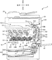
- FIG. 1 is a cross-sectional view showing the internal structure of an image forming apparatus according to an embodiment of the present invention.
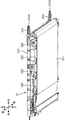
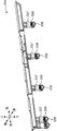
- FIG. 2 is a perspective view of the intermediate transfer unit of the image forming apparatus according to the embodiment of the present invention.
- FIG. 3 is a perspective view showing the internal structure of the intermediate transfer unit of the image forming apparatus according to the embodiment of the present invention.
- FIG. 4A is a rear view of the rack of the intermediate transfer unit according to the embodiment of the present invention.
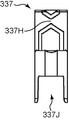
- FIG. 4B is a front view of the support member of the intermediate transfer unit according to the embodiment of the invention.
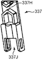
- FIG. 4C is a perspective view of a support member of the intermediate transfer unit according to the embodiment of the present invention.
- FIG. 5 is a perspective view of a state where a plurality of support members are engaged with the rack of the intermediate transfer unit according to the embodiment of the present invention.
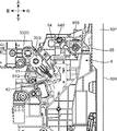
- FIG. 6 is a front view of the periphery of the transfer member inside the image forming apparatus according to the embodiment of the present disclosure.
- FIG. 7 is a front view of the periphery of the transfer member in the image forming apparatus according to the embodiment of the present invention.
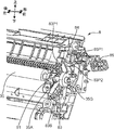
- FIG. 8 is a perspective view of the periphery of the transfer member inside the image forming apparatus according to the embodiment of the present disclosure.
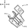
- FIG. 9A is a front view of the holding member of the image forming apparatus according to the embodiment of the present disclosure.
- FIG. 9B is a perspective view of the holding member of the image forming apparatus according to the embodiment of the present disclosure.
- FIG. 10A is a front view of the pressing member of the image forming apparatus according to the embodiment of the present disclosure.
- FIG. 10B is a perspective view of the pressing member of the image forming apparatus according to the embodiment of the present invention.
- FIG. 11A is a front view of the first link of the second interlocking mechanism of the image forming apparatus according to the embodiment of the present disclosure.
- FIG. 11B is a perspective view of the first link of the second interlocking mechanism of the image forming apparatus according to the embodiment of the present disclosure.
- FIG. 12A is a front view of the second link of the second interlocking mechanism of the image forming apparatus according to the embodiment of the present invention.
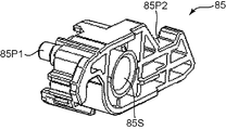
- FIG. 12B is a perspective view of the second link of the second interlocking mechanism of the image forming apparatus according to the embodiment of the present disclosure.
- FIG. 13 is a front view showing a state in which the first interlocking mechanism presses the pressing member inside the image forming apparatus according to the embodiment of the present invention.
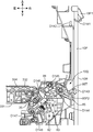
- FIG. 14 is a front view showing a state in which the second interlocking mechanism presses the pressing member inside the image forming apparatus according to the embodiment of the present invention.
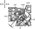
- FIG. 15A is an enlarged view of the periphery of the transfer member of FIG.
- FIG. 15B is an enlarged view of the periphery of the transfer member of FIG.
- FIG. 1 is a sectional view showing an internal structure of an image forming apparatus 1 according to an embodiment of the present invention.
- the image forming apparatus 1 a multi-function machine having a printer function and a copying function is illustrated, but the image forming apparatus may be a printer, a copier, or a facsimile machine.
- the image forming apparatus 1 includes an apparatus main body 10 (housing) having a substantially rectangular parallelepiped housing structure, and an automatic document feeder 20 disposed on the apparatus main body 10.
- a reading unit 25 that optically reads a document image to be copied
- an image forming unit 30 that forms a toner image on a sheet
- a fixing unit 60 that fixes the toner image on a sheet
- image formation A sheet feeding unit 40 that stores sheets conveyed to the unit 30, and a conveyance path 50 that conveys the sheet from the sheet feeding unit 40 or the sheet feeding tray 46 to the discharge space 10S via the image forming unit 30 and the fixing unit 60.
- the sheet S discharged to the discharge space 10S is stacked on the paper discharge unit 101.
- the automatic document feeder (ADF) 20 automatically feeds a document sheet to be copied toward a predetermined document reading position in the apparatus main body 10. On the other hand, when the user manually places the document sheet on a predetermined document reading position, the ADF 20 is opened upward.
- the reading unit 25 optically reads an image of a document sheet automatically fed from the ADF 20 on the upper surface of the apparatus main body 10 or a manually placed document sheet.
- the image forming unit 30 generates a full-color toner image and transfers it onto the sheet to form an image on the sheet.
- a toner replenishing section 34 disposed on the intermediate transfer unit 33.
- Each of the image forming units 32Y, 32M, 32C, and 32Bk includes a photosensitive drum 321 and a charger 322, an exposure unit 323, a developing device 324, and a primary transfer roller 325 (first transfer unit) arranged around the photosensitive drum 321. Moving member, stretching roller) and cleaning device 326.
- the photosensitive drum 321 rotates about its axis, forms an electrostatic latent image on its surface, and carries a toner image (developer image).
- the charger 322 uniformly charges the surface of the photosensitive drum 321.
- the exposure device 323 includes a laser light source and optical system devices such as a mirror and a lens, and forms an electrostatic latent image by irradiating the peripheral surface of the photosensitive drum 321 with light based on image data of a document image. .
- the developing device 324 supplies toner to the peripheral surface of the photosensitive drum 321 in order to develop the electrostatic latent image formed on the photosensitive drum 321.
- the primary transfer roller 325 is disposed to face the photosensitive drum 321 with an intermediate transfer belt 331 described later interposed therebetween.
- the primary transfer roller 325 primarily transfers the toner image on the photosensitive drum 321 onto the intermediate transfer belt 331.
- the cleaning device 326 cleans the peripheral surface of the photosensitive drum 321 after the toner image is transferred.
- the intermediate transfer unit 33 includes an intermediate transfer belt 331 (image carrier), a belt drive roller 332 (drive roller), and a belt driven roller 333.
- the intermediate transfer belt 331 is disposed to face the plurality of photosensitive drums 321 and is driven to rotate. On the outer peripheral surface of the intermediate transfer belt 331, toner images (developer images) are transferred from the plurality of photosensitive drums 321 to be overlapped at the same location.
- the intermediate transfer belt 331 carries a toner image while being rotated counterclockwise in FIG.
- the belt drive roller 332 is connected to a drive mechanism (not shown).
- the belt driving roller 332 contacts the inner peripheral surface of the intermediate transfer belt 331 and rotates the intermediate transfer belt 331.
- the belt driven roller 333 stretches the intermediate transfer belt 331 so as to be able to go around on the opposite side of the belt driving roller 332.
- the plurality of primary transfer rollers 325 corresponding to each color also function as tension rollers that contact the inner peripheral surface of the intermediate transfer belt 331 at positions different from the belt driving roller 332.
- a secondary transfer roller 35 (transfer member) is disposed to face the peripheral surface of the belt drive roller 332.
- the secondary transfer roller 35 is rotated by a drive mechanism (not shown) to transfer the toner image to the sheet.
- the sheet passes through the nip portion between the intermediate transfer belt 331 and the secondary transfer roller 35 that are supported by the belt driving roller 332 on the inner periphery, so that a full-color toner image that is overcoated on the intermediate transfer belt 331 is obtained. It becomes a secondary transfer portion (transfer nip portion) to be transferred to the sheet.
- the toner replenishing section 34 includes a yellow toner container 34Y, a magenta toner container 34M, a cyan toner container 34C, and a black toner container 34Bk.
- the toner of each color is supplied from the discharge screw 341 through a supply path (not shown).
- the paper feed unit 40 includes two-stage paper feed cassettes 40A and 40B that accommodate sheets S subjected to image forming processing. These paper feed cassettes 40A and 40B can be pulled out from the front of the apparatus body 10 toward the front.
- the sheet feeding cassette 40A (40B) includes a sheet storage unit 41 that stores a sheet bundle formed by stacking sheets S, and a lift plate 42 that lifts the sheet bundle for feeding.
- a pickup roller 43 and a roller pair of a paper feed roller 44 and a retard roller 45 are arranged on the upper right side of the paper feed cassette 40A (40B). By driving the pickup roller 43 and the paper feed roller 44, the uppermost sheet S of the sheet bundle in the paper feed cassette 40A is fed out one by one and carried into the upstream end of the transport path 50.
- the conveyance path 50 is printed on one side when performing double-sided printing on the sheet S and a main conveyance path 50A that conveys the sheet S from the paper feeding unit 40 to the exit of the fixing unit 60 via the image forming unit 30.
- a double-sided conveyance path 50B for returning the sheet to the image forming unit 30 and an upper discharge path 50C and a lower discharge path 50D for directing the sheet S from the downstream end of the main conveyance path 50A to the discharge space 10S are included.
- the sheet S conveyed through the upper discharge path 50C and the lower discharge path 50D is discharged into the discharge space 10S by the upper discharge roller pair 7B and the lower discharge roller pair 7A.
- a registration roller pair 51 is disposed on the upstream side of the main transfer path 50A from the secondary transfer portion 35A.
- the sheet S is temporarily stopped by the stopped registration roller pair 51, and skew correction is performed.
- the registration roller pair 51 is rotationally driven by a drive motor (not shown) at a predetermined timing for image transfer, whereby the sheet S is sent out to the secondary transfer roller 35.
- the fixing unit 60 is an induction heating type fixing device that performs a fixing process for fixing the toner image on the sheet S.
- a fixing nip portion is formed in the fixing portion 60. As the sheet S passes through the fixing nip portion, the toner image transferred to the sheet S is fixed to the sheet.
- the image forming apparatus 1 includes a transport unit 8 (FIGS. 1 and 8) and an opening / closing cover 10P (FIG. 7).
- the opening / closing cover 10 ⁇ / b> P constitutes a part of the right wall 10 ⁇ / b> R of the apparatus main body 10.
- the opening / closing cover 10P includes a fulcrum portion (not shown) at the lower end.
- the opening / closing cover 10P is rotatable with respect to the apparatus main body 10 around the fulcrum portion.
- the double-sided conveyance path 50B is opened to the outside of the apparatus main body 10 by the rotation of the opening / closing cover 10P.
- the transport unit 8 also includes a fulcrum portion (not shown) at the lower end.
- the transport unit 8 is rotatable with respect to the apparatus main body 10 about the fulcrum so as to follow the opening operation of the opening / closing cover 10P.
- the main transport path 50 ⁇ / b> A is further opened to the outside of the apparatus body 10 by the rotation of the transport unit 8.
- FIG. 2 is a perspective view of the intermediate transfer unit 33.
- FIG. 3 is a perspective view showing the internal structure of the intermediate transfer unit 33.
- 4A is a rear view of the roller contact / separation rack 334 of the intermediate transfer unit 33.
- FIG. 4B and 4C are a front view and a perspective view of the bearing holder 337 of the intermediate transfer unit 33, respectively.
- FIG. 5 is a perspective view showing a state in which a plurality of bearing holders 337 are engaged with the roller contact / separation rack 334.
- the intermediate transfer unit 33 includes a unit housing 33H and a roller contact / separation mechanism 33T (first interlocking mechanism) (FIG. 3). Compared to FIG. 2, the unit housing 33H and the intermediate transfer belt 331 are not shown in FIG.
- the unit housing 33H is a housing portion of the intermediate transfer unit 33 and has a flat box shape.
- the unit housing 33H rotatably supports the plurality of primary transfer rollers 325, the belt driving roller 332, and the belt driven roller 333 described above.
- the roller contact / separation mechanism 33T has a contact / separation function for bringing the primary transfer roller 325 into contact with or separating from the photosensitive drum 321.
- the roller contact / separation mechanism 33T includes a first position where the primary transfer roller 325 presses the intermediate transfer belt 331 against the photosensitive drum 321 and a second position where the primary transfer roller 325 separates from the photosensitive drum 321.
- the primary transfer roller 325 of each color is moved between.
- the roller contact / separation mechanism 33T includes a roller contact / separation rack 334 (rack), a drive mechanism 335, a transmission shaft 336, a bearing holder 337 (support member), a bearing 338, and a roller spring 339.
- the roller contact / separation rack 334 is a member that is disposed in a pair in the front-rear direction and extends in the left-right direction. Each roller contact / separation rack 334 is movably supported by the unit housing 33H.
- the pair of roller contact / separation racks 334 supports both ends of the plurality of primary transfer rollers 325.
- the roller contact / separation rack 334 is movable in a direction (left-right direction) connecting the axes of the plurality of primary transfer rollers 325.
- the roller contact / separation rack 334 includes a first rail 334B and a second rail 334C so as to correspond to the primary transfer roller 325 of each color.
- the first rail 334 ⁇ / b> B and the second rail 334 ⁇ / b> C are projecting pieces that project from the roller contact / separation rack 334 toward the outside of the intermediate transfer unit 33.
- the first rail 334 ⁇ / b> B and the second rail 334 ⁇ / b> C are not shown because they are located on the back side (front side) of the roller contact / separation rack 334.
- the first rail 334B extends in the left-right direction at the lower end portion of the roller contact / separation rack 334.
- the second rail 334C is an upper end portion of the roller contact / separation rack 334, and extends in the left-right direction on the left side and above the first rail 334B.
- the first rail 334B and the second rail 334C are connected by an inclined surface that rises toward the left.
- a bearing holder 337 engages with the first rail 334B and the second rail 334C.
- the drive mechanism 335 is disposed inside the unit housing 33H.
- the drive mechanism 335 is a unit composed of a motor and a plurality of gears.
- the driving mechanism 335 generates a driving force that moves the roller contact / separation rack 334.
- the transmission shaft 336 is disposed adjacent to the drive mechanism 335 inside the unit housing 33H.
- the transmission shaft 336 extends in the front-rear direction so as to straddle the pair of roller contact / separation racks 334.
- the transmission shaft 336 is connected to the gear of the drive mechanism 335.
- Transmission gears 336G are provided at both ends of the transmission shaft 336 (FIG. 3).
- the transmission gear 336G is a pinion gear that transmits a driving force to the roller contact / separation rack 334.
- the driving force generated by the driving mechanism 335 is transmitted from the transmission shaft 336 to the pair of roller contact / separation racks 334. As a result, the roller contact / separation rack 334 moves in the left-right
- the bearing holder 337 (FIGS. 4B and 4C) supports the end of the primary transfer roller 325.
- a clearance 337 ⁇ / b> H formed between a pair of triangular protrusions is disposed at the upper end of the bearing holder 337.
- the first rail 334B or the second rail 334C of the roller contact / separation rack 334 is inserted into the gap 337H.
- a housing portion 337J for rotatably supporting the primary transfer roller 325 is formed at the lower end portion of the bearing holder 337.
- the bearing 338 is disposed in the accommodating portion 337 ⁇ / b> J of the bearing holder 337.
- the rotation shaft of the primary transfer roller 325 is inserted into the cylinder of the bearing 338.
- the roller spring 339 is a spring member compressed between the inner wall portion on the upper side of the bearing holder 337 and the bearing 338. The roller spring 339 biases the primary transfer roller 325 toward the photosensitive drum 321.
- the first rail 334B described above regulates the bearing holder 337 so that the primary transfer roller 325 is disposed at the first position.
- the second rail 334C is disposed at an interval in the moving direction of the roller contact / separation rack 334 with respect to the first rail 334B, and the bearing holder 337 is disposed so that the primary transfer roller 325 is disposed at the second position. regulate.
- the roller contact / separation rack 334 of the intermediate transfer unit 33 includes a rack pressing portion 334A (FIG. 2).
- the rack pressing portion 334A is disposed at the front end portion in the moving direction (right direction) of the roller contact / separation rack 334 and can press a separation lever 83 described later. In FIG. 3, the rack pressing portion 334A is not shown.
- the bearing holder 337 corresponding to the primary transfer roller 325 of each color is engaged with the first rail 334B.
- the primary transfer roller 325 is disposed at a first position where the primary transfer roller 325 contacts the photosensitive drum 321 with the intermediate transfer belt 331 interposed therebetween, and a primary transfer nip portion of each color is formed.
- the motor of the drive mechanism 335 is rotated forward in the state shown in FIG. 3, the roller contact / separation rack 334 moves in the direction of arrow D31 in FIG.
- the bearing holder 337 engages with the second rail 334C.
- the primary transfer roller 325 is disposed at the second position by the bearing holder 337 moving upward.
- FIG. 6 and 7 are front views of the periphery of the secondary transfer roller 35 inside the image forming apparatus 1 according to the present embodiment.
- FIG. 7 in order to explain the structure around the secondary transfer roller 35, the illustration of a later-described separation lever 83 is omitted as compared with FIG. 6.
- FIG. 8 is a perspective view of the periphery of the secondary transfer roller 35 inside the image forming apparatus 1.
- the image forming apparatus 1 further includes a bush 81 (holding member), a pressing spring 82 (biasing member), a separation lever 83 (pressing member), and a separation interlocking mechanism 35T.
- FIGS. 9A and 9B are a front view and a perspective view of the bush 81 according to the present embodiment.
- the bush 81 rotatably supports the secondary transfer roller 35. Note that a pair of bushes 81 is arranged at the front end and the rear end of the transport unit 8.
- the bush 81 is movable along a direction toward the belt driving roller 332 by a bush guide 81G (FIG. 7) provided in the transport unit 8.
- the bush 81 includes a bush bearing portion 81J (shaft support portion), a bush pressed portion 81P (a separated pressed portion), and a spring locking portion 81Q (a biased portion). .
- the bush bearing portion 81J rotatably supports the secondary transfer roller shaft 35A (FIG. 8) of the secondary transfer roller 35 via a ball bearing (not shown).
- a secondary transfer roller gear 35G for transmitting a rotational driving force to the secondary transfer roller 35 is fixed to the tip of the secondary transfer roller shaft 35A of the secondary transfer roller 35. (FIG. 7).
- the secondary transfer roller gear 35G is engaged with a belt driving roller gear 332G for transmitting a rotational driving force to the belt driving roller 332.
- the belt driving roller 332 and the secondary transfer roller 35 can be rotated synchronously.
- the spring locking portion 81 ⁇ / b> Q is disposed at the lower end portion of the bush 81.
- One end of the pressing spring 82 is locked to the spring locking portion 81Q.
- the spring locking portion 81Q is urged upward and leftward by the pressing spring 82.
- the bush pressed portion 81P is disposed between the bush bearing portion 81J and the spring locking portion 81Q.
- the bush pressed portion 81P has an arch shape that is convex toward the bush bearing portion 81J.
- the bush pressed portion 81P is pressed toward the direction in which the secondary transfer roller 35 is separated from the intermediate transfer belt 331 (belt driving roller 332) by a lever pressing portion 83P3 described later of the separation lever 83.
- the pressing spring 82 is a spring member that is compressed between the bush 81 and the wall surface of the transport unit 8. The pressing spring 82 urges the bush 81 toward the intermediate transfer belt 331.
- the separation lever 83 is a lever member that is swingably supported by the transport unit 8. Referring to FIG. 10A, the separation lever 83 has a shape in which the tip is bent in a front view.
- the separation lever 83 includes a lever fulcrum part 83S (fulcrum part), a lever main body 83A, a first tip part 83B, and a second tip part 83C.
- the lever main body 83 ⁇ / b> A is a main body portion of the separation lever 83.
- the lever body 83A extends from the left side and the lower side to the right side and the upper side.
- the lever fulcrum portion 83S is a hole opened at the lower end of the lever main body 83A.
- a shaft portion (not shown) protruding from the transport unit 8 is inserted into the lever fulcrum portion 83S.
- the separation lever 83 can swing around the lever fulcrum 83S.
- the first tip 83B is disposed at the upper end (tip) of the lever body 83A.
- the first tip 83B extends from the right side and the lower side to the left and the upper side.
- a lever first pressed portion 83P1 (first pressed portion) is disposed at the upper end of the first tip portion 83B.
- the lever first pressed portion 83P1 is a pressed surface that is pressed by the rack pressing portion 334A of the roller contact / separation rack 334 of the roller contact / separation mechanism 33T described above.
- tip parts are box-shaped parts which consist of a substantially trapezoid shape by the front view arrange
- a lever second pressed portion 83P2 (second pressed portion) is formed on the upper surface of the second tip portion 83C.
- the lever second pressed portion 83P2 is a pressed surface that is pressed by the first link 84 of the cover interlocking mechanism 10Q described later.
- the lever main body 83A includes a lever pressing portion 83P3 (pressing portion).
- the lever pressing portion 83P3 is disposed between the lever fulcrum portion 83S, the lever first pressed portion 83P1, and the lever second pressed portion 83P2, and on the lower side surface of the lever main body 83A.
- the lever pressing portion 83P3 has a function of pressing the bush pressed portion 81P of the bush 81 described above.
- the separation lever 83 has a secondary transfer roller shaft 35 ⁇ / b> A between the bush 81 and the secondary transfer roller gear 35 ⁇ / b> G of the secondary transfer roller 35 in the front-rear direction (the axial direction of the secondary transfer roller 35). It is arranged below. Further, the separation lever 83 is fitted between the bush bearing portion 81J of the bush 81 and the bush pressed portion 81P (FIG. 9B). As a result, the lever pressing portion 83P3 (FIGS. 10A and 10B) is positioned immediately above the bush pressed portion 81P (FIG. 9B).
- the separation lever 83 As the separation lever 83 swings around the lever fulcrum 83S, the separation lever 83 changes its posture between the first posture (FIG. 6) and the second posture (FIG. 13). In the first posture, the separation lever 83 allows the secondary transfer roller 35 to contact the intermediate transfer belt 331 by the urging force of the pressing spring 82. On the other hand, in the second posture, the separation lever 83 presses the bush 81 against the urging force of the pressing spring 82 to separate the secondary transfer roller 35 from the intermediate transfer belt 331.
- the separation interlocking mechanism 35T (FIG. 6) has a function of separating the secondary transfer roller 35 from the belt driving roller 332.
- the separation interlock mechanism 35T does not include a dedicated motor (drive source) for separating the secondary transfer roller 35.
- the separation interlocking mechanism 35T separates the secondary transfer roller 35 using a driving force associated with the movement operation of the primary transfer roller 325 and the movement operation of the grip portion 10P1 described later.
- the roller contact / separation mechanism 33T (first interlocking mechanism) described above constitutes a part of the separation interlocking mechanism 35T.
- the roller contact / separation mechanism 33T presses the separation lever 83 in conjunction with the movement operation of the primary transfer roller 325 (contact / separation operation with respect to the photosensitive drum 321), and the separation lever 83 is moved from the first posture to the second posture. Change it.
- the separation interlocking mechanism 35T includes a cover interlocking mechanism 10Q (second interlocking mechanism) (FIG. 6).
- the opening / closing cover 10P includes a gripping portion 10P1 (second moving member, gripping lever) (FIG. 14).
- the grip portion 10P1 is swingably supported on the upper end side of the opening / closing cover 10P.
- the grip portion 10P1 is exposed outside the opening / closing cover 10P (right wall 10R).
- the cover interlocking mechanism 10Q presses the separation lever 83 in conjunction with the movement operation (swinging operation) of the grip portion 10P1, and changes the posture of the separation lever 83 from the first posture to the second posture.
- the cover interlocking mechanism 10Q includes a first link 84, a second link 85, and a lever link 86.
- 11A and 11B are a front view and a perspective view of the first link 84 of the cover interlocking mechanism 10Q.
- 12A and 12B are a front view and a perspective view of the second link 85 of the cover interlocking mechanism 10Q.
- FIG. 13 is a front view showing a state in which the rack pressing portion 334A of the roller contact / separation mechanism 33T presses the separation lever 83 inside the image forming apparatus 1 according to the present embodiment.
- FIG. 14 is a front view showing a state where the cover interlocking mechanism 10Q presses the separation lever 83 inside the image forming apparatus 1 according to the present embodiment.
- the first link 84 is rotatably supported by the transport unit 8 on the right side and above the separation lever 83 (FIG. 13).
- the first link 84 is a member extending in the left-right direction.
- the first link 84 includes a first link fulcrum part 84S, a first link pressing part 84P1, and a first link pressed part 84P2 (FIGS. 11A and 11B).
- the first link fulcrum portion 84S is a central portion in the left-right direction of the first link 84, and is a hole formed so as to penetrate in the front-rear direction (the direction orthogonal to the paper surface of FIG. Part.
- the first link pressing portion 84P1 is a lower surface portion on the left end side of the first link 84.
- the first link pressing portion 84P1 has a function of pressing the lever second pressed portion 83P2 (FIGS. 10A and 10B) of the separation lever 83 described above.
- the 1st link 84 is provided with the crevice formed because the wall surface of the right side rather than the 1st link fulcrum part 84S sinks back.
- the first link pressed portion 84P2 is an inner wall surface of the first link 84 formed by the concave portion.
- the first link pressed portion 84P2 is pressed by a pressing pin 85P1 of the second link 85 described later.
- the second link 85 is rotatably supported by the transport unit 8 between the first link 84 and the opening / closing cover 10P. As shown in FIG. 8, the second link 85 is disposed in front of the first link 84.
- the second link 85 includes a second link fulcrum portion 85S, a pressing pin 85P1, and a second link pressed portion 85P2.
- the second link fulcrum portion 85S is disposed at a position slightly shifted leftward from the center portion of the second link 85 in the left-right direction.
- the second link fulcrum 85S is a hole formed through the second link 85 in the front-rear direction (a direction orthogonal to the paper surface of FIG. 12A).
- a shaft portion (not shown) protruding from the transport unit 8 is inserted into the second link fulcrum portion 85S. As a result, the second link 85 can be rotated around the second link fulcrum 85S.
- the pressing pin 85P1 is a pin protruding rearward from the rear side surface of the second link 85 on the left side of the second link fulcrum portion 85S.
- the pressing pin 85P1 is inserted into the concave portion on the right side of the first link 84.
- the pressing pin 85P1 has a function of pressing the first link pressed portion 84P2.
- the second link pressed portion 85P2 is an upper surface portion of a hook portion formed to the right of the second link fulcrum portion 85S.
- the second link pressed portion 85P2 is pressed by the lever link 86.
- the lever link 86 (FIGS. 6 and 14) is disposed so as to extend in the vertical direction inside the opening / closing cover 10P.
- the upper end portion of the lever link 86 is connected to the grip portion 10P1.
- a lever hook 86T (FIG. 14) is disposed at the lower end of the lever link 86.
- the lever hook 86 ⁇ / b> T is exposed inside the apparatus main body 10 (FIG. 1) of the image forming apparatus 1 and is disposed to face the second link pressed portion 85 ⁇ / b> P ⁇ b> 2 of the second link 85.
- the manner in which the secondary transfer roller 35 is separated from the intermediate transfer belt 331 (belt drive roller 332) in conjunction with the separation operation of the primary transfer roller 325 will be described in detail.
- the image forming apparatus 1 when the image forming operation is completed, it is desirable that the tension of the intermediate transfer belt 331 is reduced. As a result, it is possible to prevent the intermediate transfer belt 331 from being subjected to plastic deformation (bending or curling).
- the roller contact / separation rack 334 is moved by the driving force of the driving mechanism 335, whereby the primary transfer roller 325 moves from the first position to the second position, and the photosensitive drum. Separate from 321.
- the secondary transfer roller 35 is separated from the intermediate transfer belt 331 in conjunction with the separation operation of the primary transfer roller 325. Therefore, in addition to the plastic deformation of the intermediate transfer unit 33, it is possible to prevent a history due to plastic deformation and nip pressure from occurring on the peripheral surface of the secondary transfer roller 35. At this time, the primary transfer roller 325 and the secondary transfer roller 35 are simultaneously separated by the roller contact / separation mechanism 33T and the separation lever 83. As a result, it is not necessary to provide a dedicated drive source for each separation operation, and space saving and cost reduction of the image forming apparatus 1 are realized.
- the user opens the opening / closing cover 10P or the conveyance unit 8 so that the main conveyance path 50A or the double-side conveyance path 50B is set in the apparatus. It is exposed outside the main body 10. As a result, the sheet S can be removed.
- the secondary transfer roller 35 is located below the belt driving roller 332 and on the right side (opening / closing cover 10 ⁇ / b> P side).
- the opening / closing cover 10 ⁇ / b> P and the transport unit 8 are opened with respect to the apparatus main body 10 by being rotated about a fulcrum portion disposed on the lower end side.
- the secondary transfer roller 35 When the transport unit 8 is rotated with the fulcrum portion as a fulcrum, if the secondary transfer roller 35 remains in contact with the belt driving roller 332 via the intermediate transfer belt 331, the secondary transfer roller 35 is in the middle. The secondary transfer roller 35 is moved rightward and upward from the state of FIG. 6 while being rubbed strongly with the transfer belt 331. As a result, rubbing scratches are generated on the surface of the intermediate transfer belt 331, resulting in image defects.
- the separating operation of the secondary transfer roller 35 is realized in conjunction with the opening operation of the opening / closing cover 10P and the transport unit 8. That is, referring to FIG. 14, when the user grips gripping part 10P1, gripping part 10P1 is swung as indicated by arrow D141. As a result, the lever link 86 (FIG. 6) inside the opening / closing cover 10P moves downward as indicated by an arrow D142. Then, the lever hook 86T of the lever link 86 pushes down the second link pressed portion 85P2 of the second link 85 (arrow D143). As a result, the second link 85 rotates with the second link fulcrum portion 85S (FIG.
- the lever pressing portion 83P3 (FIG. 10A) of the separation lever 83 presses the bush pressed portion 81P (FIG. 9B) of the pressing spring 82 (arrow D148).
- the bush 81 (FIG. 8) moves downward and to the right against the urging force of the pressing spring 82, and the secondary transfer roller 35 is separated from the intermediate transfer belt 331.
- the secondary transfer roller 35 is separated from the intermediate transfer belt 331 in conjunction with the gripping operation when the user grips the gripping portion 10P1. For this reason, the secondary transfer roller 35 is prevented from rubbing against the belt driving roller 332 when the opening / closing cover 10P is opened. Further, since the secondary transfer roller 35 is separated using the gripping force of the user, it is not necessary to provide a dedicated drive source for the separation operation of the secondary transfer roller 35.
- FIG. 15A is an enlarged view of the periphery of the secondary transfer roller 35 of FIG.
- FIG. 15B is an enlarged view of the periphery of the secondary transfer roller 35 of FIG.
- the rack pressing portion 334A of the roller contact / separation mechanism 33T presses the lever first pressed portion 83P1 of the separation lever 83, so that the secondary transfer roller 35 is separated from the belt driving roller 332. Is defined as L1.
- the first link pressing portion 84P1 of the cover interlocking mechanism 10Q presses the lever second pressed portion 83P2 of the separating lever 83, so that the secondary transfer roller 35 is separated from the belt driving roller 332.
- the separation distance is defined as L2.
- the movable ranges of the roller contact / separation mechanism 33T, the cover interlocking mechanism 10Q, and the separation lever 83 are set in advance so as to satisfy the relationship of L1 ⁇ L2.
- the secondary transfer roller 35 when the secondary transfer roller 35 is separated in conjunction with the separation operation of the primary transfer roller 325, the purpose is mainly to loosen the tension of the intermediate transfer belt 331.
- the secondary transfer roller 35 when the secondary transfer roller 35 is separated in conjunction with the opening operation of the opening / closing cover 10 ⁇ / b> P and the transport unit 8, the purpose is to expose the main transport path 50 ⁇ / b> A to the outside of the apparatus main body 10.
- the relationship of L1 ⁇ L2 is satisfied as described above. It is desirable.
- the secondary transfer roller 35 prior to opening the opening / closing cover 10P, the secondary transfer roller 35 can be largely separated from the belt driving roller 332 in conjunction with the operation of gripping the grip portion 10P1.
- the lever fulcrum portion 83S functions as a fulcrum of the lever principle.
- the lever first pressed portion 83P1 or the lever second pressed portion 83P2 functions as a power point of the lever principle.
- the secondary transfer roller 35 is separated from the belt driving roller 332 only by applying a force smaller than the urging force of the pressing spring 82 to the lever first pressed portion 83P1 or the lever second pressed portion 83P2. Is possible.
- the separation lever 83 since the separation lever 83 includes the lever first pressed portion 83P1 and the lever second pressed portion 83P2, it is possible to apply a pressing force to the separation lever 83 from different directions.
- the separation lever 83 is disposed between the intermediate transfer unit 33 and the opening / closing cover 10P.
- the pressing force to the lever first pressed portion 83P1 is transmitted from the intermediate transfer unit 33 side toward the opening / closing cover 10P side.
- the pressing force to the lever second pressed portion 83P2 is transmitted from the opening / closing cover 10P side toward the intermediate transfer unit 33 side.
- the image forming apparatus 1 has been described above. According to the above configuration, the secondary transfer roller 35 can be separated from the intermediate transfer belt 331 in conjunction with the movement operation of the plurality of moving members without increasing the number of drive sources.
- this invention is not limited to these, For example, the following modified embodiment is employable.
- the transport unit 8 has been described as functioning as a housing that rotatably supports the secondary transfer roller 35, but the present invention is not limited to this.
- the image forming apparatus 1 may be provided with another housing that supports the secondary transfer roller 35 separately from the transport unit 8.
- the roller contact / separation mechanism 33T has been described in the form of separating the secondary transfer roller 35 from the belt driving roller 332 in conjunction with the separating operation of the primary transfer roller 325.
- the present invention is not limited to this.
- the roller separated by the roller contact / separation mechanism 33T may be another stretching roller that contacts the inner peripheral surface of the intermediate transfer belt 331.
- the roller contact / separation mechanism 33T includes a first position where the stretching roller presses the inner peripheral surface of the intermediate transfer belt 331, and a second position separated from the inner peripheral surface of the intermediate transfer belt 331 than the first position. The tension roller is moved between the positions. Further, the roller contact / separation mechanism 33T may press the lever first pressed portion 83P1 of the separation lever 83 in conjunction with the movement of the tension roller from the first position to the second position.
Landscapes
- Physics & Mathematics (AREA)
- General Physics & Mathematics (AREA)
- Electrostatic Charge, Transfer And Separation In Electrography (AREA)
- Electrophotography Configuration And Component (AREA)
Abstract
Description
画像形成装置1は、略直方体形状の筐体構造を有する装置本体10(筐体)と、装置本体10上に配置される自動原稿給送装置20とを備える。装置本体10の内部には、複写する原稿画像を光学的に読み取る読取ユニット25と、シートにトナー像を形成する画像形成部30と、前記トナー像をシートに定着させる定着部60と、画像形成部30へ搬送されるシートを貯留する給紙部40と、シートを給紙部40又は給紙トレイ46から画像形成部30及び定着部60を経由して排出空間10Sまで搬送する搬送経路50と、が収容されている。排出空間10Sに排出されたシートSは、排紙部101に積載される。
Claims (8)
- 現像剤像を担持する像担持体と、
前記像担持体に当接され、前記像担持体との間でシートが通過する転写ニップ部を形成し、前記現像剤像を前記シートに転写する転写部材と、
前記転写部材を保持する保持部材と、
前記保持部材を前記像担持体に向かって付勢する付勢部材と、
前記付勢部材の付勢力によって前記転写部材が前記像担持体に当接する第1の姿勢と、前記付勢部材の付勢力に抗して前記保持部材を押圧し、前記転写部材を前記像担持体から離間させる第2の姿勢との間で、姿勢変更可能な押圧部材と、
移動可能な第1移動部材と、
移動可能な第2移動部材と、
前記第1移動部材に連動して前記押圧部材を押圧し、前記押圧部材を前記第1の姿勢から前記第2の姿勢に姿勢変更させる第1連動機構と、
前記第2移動部材に連動して前記押圧部材を押圧し、前記押圧部材を前記第1の姿勢から前記第2の姿勢に姿勢変更させる第2連動機構と、
を有し、
前記押圧部材は、前記第1連動機構によって押圧される第1被押圧部と、前記第2連動機構によって押圧される第2被押圧部と、を備える画像形成装置。 - 回転され、表面に静電潜像が形成される複数の感光体ドラムと、
前記複数の感光体ドラムに対向して配置され、周回駆動される中間転写ベルトと、
前記転写部材に対向して配置され、前記中間転写ベルトの内周面に当接し、前記中間転写ベルトを周回させる駆動ローラーと、
前記駆動ローラーとは異なる位置で、前記中間転写ベルトの内周面に当接する張架ローラーと、
を有し、
前記像担持体は、前記中間転写ベルトであって、
前記第1移動部材は、前記張架ローラーであって、
前記第1連動機構は、前記張架ローラーが前記中間転写ベルトの内周面を押圧する第1の位置と、前記第1の位置よりも前記中間転写ベルトの内周面から離間した第2の位置との間で、前記張架ローラーを移動させ、かつ、前記張架ローラーの前記第1の位置から前記第2の位置への移動に連動して、前記押圧部材の前記第1被押圧部を押圧する請求項1に記載の画像形成装置。 - 前記中間転写ベルトを挟んで前記複数の感光体ドラムに対向して配置され、前記感光体ドラムから前記中間転写ベルトに前記現像剤像を転写させる複数の一次転写ローラーを有し、
前記張架ローラーは、前記複数の一次転写ローラーであって、
前記第1連動機構は、前記一次転写ローラーが前記中間転写ベルトを前記感光体ドラムに押圧する前記第1の位置と、前記一次転写ローラーが前記感光体ドラムから離間する前記第2の位置との間で、前記一次転写ローラーを移動させる請求項2に記載の画像形成装置。 - 前記第1連動機構は、
前記複数の一次転写ローラーの軸心同士を結ぶ方向に移動可能なラックと、
前記ラックを移動させる駆動機構と、
前記ラックに係合され、かつ、前記一次転写ローラーをそれぞれ回転可能に支持する複数の支持部材と、
を有し、
前記ラックは、前記一次転写ローラーが前記第1の位置に配置されるように前記支持部材を規制する第1レールと、前記第1レールに対して前記ラックの移動方向に間隔をおいて配置され、前記一次転写ローラーが前記第2の位置に配置されるように前記支持部材を規制する第2レールと、前記ラックの前記移動方向の先端部に配置され、前記押圧部材を押圧可能なラック押圧部と、を備え、
前記ラックが前記駆動機構によって移動され、前記一次転写ローラーが前記第1の位置から前記第2の位置に移動されることに連動して、前記ラック押圧部が前記押圧部材の前記第1被押圧部を押圧する請求項3に記載の画像形成装置。 - 前記押圧部材は、
支点部と、
前記第1被押圧部および前記第2被押圧部と、
前記支点部と前記第1被押圧部および前記第2被押圧部との間に配置され、前記保持部材を押圧する押圧部と、
を備え、
前記第1被押圧部または前記第2被押圧部が押圧されると、前記押圧部材が前記支点部回りに回動することで、前記押圧部が前記保持部材を押圧する請求項1に記載の画像形成装置。 - 前記保持部材は、
前記転写部材を回転可能に支持する軸支部と、
前記付勢部材によって付勢される被付勢部と、
前記軸支部と前記被付勢部との間に配置され、前記押圧部材の前記押圧部によって、前記転写部材が前記像担持体から離れる方向に向かって押圧される離間用被押圧部と、
を備える請求項5に記載の画像形成装置。 - 筐体と、
前記筐体に対して開閉可能な開閉カバーと、
前記開閉カバーに揺動可能に支持され、前記開閉カバーの前記筐体に対する開放動作において把持される把持レバーと、
を更に有し、
前記第2移動部材は、前記把持レバーであって、
前記第2連動機構は、前記把持レバーが把持され揺動することに連動して、前記押圧部材の前記第2被押圧部を押圧する請求項1乃至6の何れか1項に記載の画像形成装置。 - 前記第2連動機構は、
回動可能とされ、前記押圧部材の前記第2被押圧部を押圧可能な第1リンクと、
前記把持レバーの揺動に連動して下方に移動可能なレバーリンクと、
前記下方に移動したレバーリンクに押圧されることで回動可能とされ、前記第1リンクを回動させる第2リンクと、
を備える請求項7に記載の画像形成装置。
Priority Applications (4)
| Application Number | Priority Date | Filing Date | Title |
|---|---|---|---|
| EP16776459.6A EP3220204B1 (en) | 2015-04-06 | 2016-03-31 | Image forming device |
| CN201680003740.8A CN107003637B (zh) | 2015-04-06 | 2016-03-31 | 图像形成装置 |
| US15/529,121 US9977375B2 (en) | 2015-04-06 | 2016-03-31 | Image forming device |
| JP2017510948A JP6369627B2 (ja) | 2015-04-06 | 2016-03-31 | 画像形成装置 |
Applications Claiming Priority (2)
| Application Number | Priority Date | Filing Date | Title |
|---|---|---|---|
| JP2015077613 | 2015-04-06 | ||
| JP2015-077613 | 2015-04-06 |
Publications (1)
| Publication Number | Publication Date |
|---|---|
| WO2016163292A1 true WO2016163292A1 (ja) | 2016-10-13 |
Family
ID=57071850
Family Applications (1)
| Application Number | Title | Priority Date | Filing Date |
|---|---|---|---|
| PCT/JP2016/060610 Ceased WO2016163292A1 (ja) | 2015-04-06 | 2016-03-31 | 画像形成装置 |
Country Status (5)
| Country | Link |
|---|---|
| US (1) | US9977375B2 (ja) |
| EP (1) | EP3220204B1 (ja) |
| JP (1) | JP6369627B2 (ja) |
| CN (1) | CN107003637B (ja) |
| WO (1) | WO2016163292A1 (ja) |
Families Citing this family (4)
| Publication number | Priority date | Publication date | Assignee | Title |
|---|---|---|---|---|
| JP6890955B2 (ja) * | 2016-11-25 | 2021-06-18 | キヤノン株式会社 | 画像形成装置 |
| JP7414549B2 (ja) * | 2020-01-22 | 2024-01-16 | キヤノン株式会社 | 画像形成装置 |
| US12228868B2 (en) | 2022-06-06 | 2025-02-18 | Ricoh Company, Ltd. | Transfer device and image forming apparatus |
| JP2025129703A (ja) * | 2024-02-26 | 2025-09-05 | 京セラドキュメントソリューションズ株式会社 | ベルト搬送装置の組み立て方法 |
Citations (7)
| Publication number | Priority date | Publication date | Assignee | Title |
|---|---|---|---|---|
| JPH10301462A (ja) * | 1997-05-01 | 1998-11-13 | Ricoh Co Ltd | 画像形成装置 |
| JP2009294357A (ja) * | 2008-06-04 | 2009-12-17 | Ricoh Co Ltd | 画像形成装置 |
| JP2010134149A (ja) * | 2008-12-04 | 2010-06-17 | Sharp Corp | カラー画像形成装置 |
| JP2011158622A (ja) * | 2010-01-29 | 2011-08-18 | Kyocera Mita Corp | 画像形成装置 |
| JP2011180215A (ja) * | 2010-02-26 | 2011-09-15 | Kyocera Mita Corp | 画像形成装置 |
| JP2013250366A (ja) * | 2012-05-31 | 2013-12-12 | Brother Ind Ltd | 画像形成装置 |
| JP2015210411A (ja) * | 2014-04-28 | 2015-11-24 | キヤノン株式会社 | 画像形成装置 |
Family Cites Families (7)
| Publication number | Priority date | Publication date | Assignee | Title |
|---|---|---|---|---|
| JP2005091613A (ja) | 2003-09-16 | 2005-04-07 | Sharp Corp | 画像形成装置の無端ベルト支持機構及びそれを用いた画像形成装置 |
| US7761020B2 (en) * | 2006-12-13 | 2010-07-20 | Sharp Kabushiki Kaisha | Image forming apparatus utilizing cylindrical toner particles |
| JP5071433B2 (ja) * | 2009-05-01 | 2012-11-14 | 富士ゼロックス株式会社 | 画像形成装置 |
| US8571439B2 (en) * | 2009-10-16 | 2013-10-29 | Sharp Kabushiki Kaisha | Image forming apparatus |
| JP5346914B2 (ja) * | 2010-12-27 | 2013-11-20 | 京セラドキュメントソリューションズ株式会社 | 画像形成装置 |
| JP5959908B2 (ja) * | 2012-04-13 | 2016-08-02 | キヤノン株式会社 | 画像形成装置 |
| JP2015118114A (ja) * | 2013-12-16 | 2015-06-25 | キヤノン株式会社 | 画像形成装置 |
-
2016
- 2016-03-31 CN CN201680003740.8A patent/CN107003637B/zh active Active
- 2016-03-31 JP JP2017510948A patent/JP6369627B2/ja active Active
- 2016-03-31 WO PCT/JP2016/060610 patent/WO2016163292A1/ja not_active Ceased
- 2016-03-31 US US15/529,121 patent/US9977375B2/en active Active
- 2016-03-31 EP EP16776459.6A patent/EP3220204B1/en active Active
Patent Citations (7)
| Publication number | Priority date | Publication date | Assignee | Title |
|---|---|---|---|---|
| JPH10301462A (ja) * | 1997-05-01 | 1998-11-13 | Ricoh Co Ltd | 画像形成装置 |
| JP2009294357A (ja) * | 2008-06-04 | 2009-12-17 | Ricoh Co Ltd | 画像形成装置 |
| JP2010134149A (ja) * | 2008-12-04 | 2010-06-17 | Sharp Corp | カラー画像形成装置 |
| JP2011158622A (ja) * | 2010-01-29 | 2011-08-18 | Kyocera Mita Corp | 画像形成装置 |
| JP2011180215A (ja) * | 2010-02-26 | 2011-09-15 | Kyocera Mita Corp | 画像形成装置 |
| JP2013250366A (ja) * | 2012-05-31 | 2013-12-12 | Brother Ind Ltd | 画像形成装置 |
| JP2015210411A (ja) * | 2014-04-28 | 2015-11-24 | キヤノン株式会社 | 画像形成装置 |
Also Published As
| Publication number | Publication date |
|---|---|
| CN107003637B (zh) | 2020-03-20 |
| CN107003637A (zh) | 2017-08-01 |
| JP6369627B2 (ja) | 2018-08-08 |
| EP3220204B1 (en) | 2020-05-27 |
| US20180024472A1 (en) | 2018-01-25 |
| US9977375B2 (en) | 2018-05-22 |
| JPWO2016163292A1 (ja) | 2017-08-10 |
| EP3220204A1 (en) | 2017-09-20 |
| EP3220204A4 (en) | 2018-07-18 |
Similar Documents
| Publication | Publication Date | Title |
|---|---|---|
| US10040652B2 (en) | Sheet feeding apparatus, sheet conveyance apparatus, and image forming apparatus | |
| JP6369627B2 (ja) | 画像形成装置 | |
| US9933729B2 (en) | Image forming apparatus including holding member movable between a plurality of positions to make intermediate transfer belt come into contact with and separate from photosensitive body | |
| JP5409676B2 (ja) | 定着装置及び画像形成装置 | |
| JP5201894B2 (ja) | 画像形成装置 | |
| JP5330906B2 (ja) | 画像形成装置 | |
| US7349650B2 (en) | Printer apparatus | |
| JP6323377B2 (ja) | シート搬送装置、およびこれを備えた画像形成装置 | |
| JP6338014B2 (ja) | 画像形成装置 | |
| JP2022165781A (ja) | シート給送装置及び画像形成装置 | |
| JP2022016967A (ja) | シート給送装置及び画像形成装置 | |
| JP6269555B2 (ja) | 転写装置、およびこれを備えた画像形成装置 | |
| JP2017151359A (ja) | 開閉ユニットおよびそれを備えた画像形成装置 | |
| JP2014026079A (ja) | シート搬送装置、およびこれを備える画像形成装置 | |
| JP4860947B2 (ja) | 画像形成装置 | |
| JP6668927B2 (ja) | シート材給送装置及び画像形成装置 | |
| JP6668962B2 (ja) | シート材給送装置及び画像形成装置 | |
| JP5593898B2 (ja) | 画像形成装置 | |
| JP2014044297A (ja) | 画像形成装置 | |
| JP5013174B2 (ja) | 画像形成装置 | |
| JP2012037914A (ja) | 画像形成装置 | |
| JP7087449B2 (ja) | 画像形成装置 | |
| US20220033204A1 (en) | Sheet feeding device and image forming apparatus | |
| CN118684024A (zh) | 薄片体供给装置和包括该薄片体供给装置的图像形成装置 | |
| JP5509115B2 (ja) | 画像形成装置 |
Legal Events
| Date | Code | Title | Description |
|---|---|---|---|
| 121 | Ep: the epo has been informed by wipo that ep was designated in this application |
Ref document number: 16776459 Country of ref document: EP Kind code of ref document: A1 |
|
| ENP | Entry into the national phase |
Ref document number: 2017510948 Country of ref document: JP Kind code of ref document: A |
|
| WWE | Wipo information: entry into national phase |
Ref document number: 15529121 Country of ref document: US |
|
| REEP | Request for entry into the european phase |
Ref document number: 2016776459 Country of ref document: EP |
|
| NENP | Non-entry into the national phase |
Ref country code: DE |