WO2016163532A1 - 発光ダイオード式照明装置 - Google Patents
発光ダイオード式照明装置 Download PDFInfo
- Publication number
- WO2016163532A1 WO2016163532A1 PCT/JP2016/061598 JP2016061598W WO2016163532A1 WO 2016163532 A1 WO2016163532 A1 WO 2016163532A1 JP 2016061598 W JP2016061598 W JP 2016061598W WO 2016163532 A1 WO2016163532 A1 WO 2016163532A1
- Authority
- WO
- WIPO (PCT)
- Prior art keywords
- light
- led element
- reflecting member
- led
- tube
- Prior art date
- Legal status (The legal status is an assumption and is not a legal conclusion. Google has not performed a legal analysis and makes no representation as to the accuracy of the status listed.)
- Ceased
Links
Images


Classifications
-
- F—MECHANICAL ENGINEERING; LIGHTING; HEATING; WEAPONS; BLASTING
- F21—LIGHTING
- F21K—NON-ELECTRIC LIGHT SOURCES USING LUMINESCENCE; LIGHT SOURCES USING ELECTROCHEMILUMINESCENCE; LIGHT SOURCES USING CHARGES OF COMBUSTIBLE MATERIAL; LIGHT SOURCES USING SEMICONDUCTOR DEVICES AS LIGHT-GENERATING ELEMENTS; LIGHT SOURCES NOT OTHERWISE PROVIDED FOR
- F21K9/00—Light sources using semiconductor devices as light-generating elements, e.g. using light-emitting diodes [LED] or lasers
- F21K9/60—Optical arrangements integrated in the light source, e.g. for improving the colour rendering index or the light extraction
- F21K9/68—Details of reflectors forming part of the light source
-
- F—MECHANICAL ENGINEERING; LIGHTING; HEATING; WEAPONS; BLASTING
- F21—LIGHTING
- F21S—NON-PORTABLE LIGHTING DEVICES; SYSTEMS THEREOF; VEHICLE LIGHTING DEVICES SPECIALLY ADAPTED FOR VEHICLE EXTERIORS
- F21S2/00—Systems of lighting devices, not provided for in main groups F21S4/00 - F21S10/00 or F21S19/00, e.g. of modular construction
-
- F—MECHANICAL ENGINEERING; LIGHTING; HEATING; WEAPONS; BLASTING
- F21—LIGHTING
- F21V—FUNCTIONAL FEATURES OR DETAILS OF LIGHTING DEVICES OR SYSTEMS THEREOF; STRUCTURAL COMBINATIONS OF LIGHTING DEVICES WITH OTHER ARTICLES, NOT OTHERWISE PROVIDED FOR
- F21V7/00—Reflectors for light sources
Definitions
- the present invention relates to a light-emitting diode illuminating device characterized by a heat dissipation / reflection structure, and more particularly to a straight tube light-emitting diode illuminating device.
- LEDs emit light when a voltage is applied to a semiconductor element. It is well known to mount an element on a substrate and conduct electricity, but dissipate the heat generated when electricity is passed through the LED element. To do so, a heat sink is essential.
- LEDs can reduce power consumption and produce the same illuminance and light energy as conventional incandescent and fluorescent lamps, and are expected to become more popular in the future. Yes.
- a straight tube type LED lighting tube that has the same appearance as a fluorescent lamp and can be directly attached to an existing fluorescent lamp fixture is a typical LED light source.
- LED lighting tubes are roughly divided into those for general lighting and plant cultivation, each of which is a semi-transparent or cylindrical shape made up of a light emitting surface made of transparent glass or synthetic resin and a heat sink for heat dissipation of the LED substrate. It is a tube. Inside the tube body, LED elements are mounted on one surface at predetermined intervals, and a circuit board through which a current flows is provided.
- the LED illuminating tube has a shape similar to that of a straight tube fluorescent lamp as a whole, and a base is mounted on both sides of the tube body, and terminals for connecting to the fixture are formed to protrude.
- the LED lighting tube can be attached to an existing fluorescent lamp fixture as well as newly installed, and the LED in the tube can emit light by receiving power supply from the LED lighting tube.
- Patent Document 1 a cylindrical tubular body made of polycarbonate and an aluminum attached to an opening provided in a part of the periphery of the tubular body are disclosed.
- An LED illuminating tube comprising a heat sink made of metal and a plurality of LEDs mounted in the tube is disclosed.
- an annular structure having an internal cavity is constituted by a translucent casing and a heat sink having a holding portion coupled to the casing, and is fixed in a heat conductive manner to the holding portion of the heat sink.
- An LED lighting tube is disclosed that includes a circuit board, one or more LED light sources attached to the circuit board, and two end caps fitted to the ends of the tubular structure. In Patent Document 2, it can be used by attaching to a fluorescent lamp fixture instead of a conventional fluorescent lamp, and uniformly illuminates at a wide angle.
- Patent Document 1 Japanese Patent Application Laid-Open No. 2011-113876 Japanese Patent Application Laid-Open No. 2013-219004
- the present invention has been made in view of the conventional drawbacks, and its object is to emit light emitted from an LED element as a light source with a wide irradiation angle of 160 to 180 degrees and high illuminance (total luminous flux). It is providing a type lighting device.
- An LED illuminating tube comprising a total luminous flux transmissive plate disposed in the light irradiation direction; LED elements disposed on a substrate facing the total luminous flux transmitting plate in the LED illumination tube; A light reflecting member provided with a light reflecting surface disposed on the light emitting side of the LED element, and the light reflecting member is symmetrically or asymmetrically light with respect to the center line of the LED element.
- the light reflecting and reflecting surface of the light reflecting member has a light directivity forming surface for irradiating the light emitted from the LED element to the outside of the tube through the total luminous flux transmitting plate by giving the light directivity to the light, Light for confining the light emitted from the LED element in the total luminous flux transmission plate and / or in the space between the total luminous flux transmission plate and the light reflecting member and irradiating the outside of the tube through the total luminous flux transmission plate
- a containment means Light-emitting diode type lighting device.
- An LED illuminating tube comprising a total luminous flux transmissive plate disposed in the light irradiation direction; LED elements disposed on a substrate facing the total luminous flux transmitting plate in the LED illumination tube; A light reflection member provided with a condensing reflection surface having a light reflection characteristic disposed on the light emitting side of the LED element; The light reflecting member is disposed to extend in the light irradiation direction symmetrically or asymmetrically with respect to the center line of the LED element, The light reflecting and reflecting surface of the light reflecting member has a light directivity forming surface for irradiating the light emitted from the LED element to the outside of the tube through the total luminous flux transmitting plate by giving the light directivity to the light, A pseudo LED element forming surface for projecting a pseudo LED element of the LED element, When the LED element is viewed from the direction of light emitted from the LED element disposed on the substrate, the pseudo LED element of the LED element disposed on the substrate appears on the pseudo LED formation surface. Diode-
- An LED illuminating tube comprising a total luminous flux transmissive plate disposed in the light irradiation direction; LED elements disposed on a substrate facing the total luminous flux transmitting plate in the LED illumination tube; A light reflection member provided with a condensing reflection surface having a light reflection characteristic disposed on the light emitting side of the LED element;
- the light reflecting member includes a first light reflecting member and a second light reflecting member,
- the first light reflecting member includes a condensing reflection surface having a light reflection characteristic disposed on the light emitting side of the LED element,
- the first light reflecting member is arranged to extend in the light irradiation direction symmetrically or asymmetrically with respect to the center line of the LED element,
- the condensing reflection surface of the first light reflecting member has a light directivity forming surface for giving the light emitted from the LED element light directivity and irradiating the LED illumination tube outside the tube through the total luminous flux transmission plate,
- An LED illuminating tube comprising a total luminous flux transmissive plate disposed in the light irradiation direction; LED elements disposed on a substrate facing the total luminous flux transmitting plate in the LED illumination tube; A light reflection member provided with a condensing reflection surface having a light reflection characteristic disposed on the light emitting side of the LED element;
- the light reflecting member includes a first light reflecting member and a second light reflecting member,
- the first light reflecting member includes a condensing reflection surface having a light reflection characteristic disposed on the light emitting side of the LED element,
- the first light reflecting member is arranged to extend in the light irradiation direction symmetrically or non-target with respect to the center line of the LED element,
- the condensing reflection surface of the first light reflecting member has a light directivity forming surface for giving the light emitted from the LED element light directivity and irradiating the LED illumination tube outside the tube through the total luminous flux transmission plate,
- a pseudo LED element forming surface for projecting
- the light emitting diode type illumination device is disposed at a position where it does not interfere with light emitted from the LED element.
- the cylindrical tubular body includes a locking member that locks the light reflecting member.
- the light reflecting member is made of a resin material.
- a third light reflecting member that connects the first light reflecting member and the second light reflecting member is provided.
- the pseudo LED element forming surface is defined and formed by the total reflectance of the first reflecting member, the elevation angle of the first reflecting member, and the distance between the LED element installation end and the first reflecting member. It is characterized by that.
- the first light reflecting plate is characterized in that an elevation angle with respect to the substrate is set to 50 to 75 degrees.
- the distance between the LED element installation end and the condensing reflection surface of the front reflecting member is 0.1 mm to 5.0 mm, the elevation angle with the substrate surface is 50 degrees to 75 degrees, and the first The height of the light reflecting plate is set to 5 times or more of the width of the LED element, preferably 10 mm to 20 mm.
- the pseudo LED element forming surface is at least one of the total reflectance of the light reflecting surface, the elevation angle of the first light reflecting member, and the interval length between the LED element installation end and the condensing reflecting surface of the reflecting member.
- the number of the pseudo LED elements projected on the pseudo LED forming surface is varied and projected by changing one of the two.
- the second reflection member and / or the all-light transmission plate may include a light confinement recess.
- the total light speed transmission plate has a total light speed transmittance of 95% or more.
- the total reflectance of the light reflecting member is defined by 80% or more.
- the light reflecting surface of the first reflecting member may be different in total reflectance and / or shape between the light directivity forming surface and the pseudo LED element forming surface.
- the second light reflecting member includes a heat sink.
- the light emitting diode type illumination device is a straight tube type light emitting diode type illumination device.
- An electronic device including a light emitting diode illumination device.
- a plant factory with light-emitting diode lighting equipment A plant factory with light-emitting diode lighting equipment.
- An LED signboard provided with a light emitting diode illumination device.
- an object of the present invention is to provide a light emitting diode illumination device capable of irradiating light emitted from an LED element with high illumination intensity (total luminous flux) at a wide irradiation angle of 160 to 180 degrees.
- FIG. 5A shows a photograph irradiated from the illumination tube through the total luminous flux transmission plate from the state where the light emitted from the LED element is confined.
- FIG. 5B shows a photograph irradiated from a state where light emitted from the LED element is not confined.
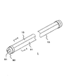
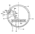
- FIG. 1 is a schematic view showing a light emitting diode illumination device according to the present invention.
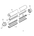
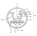
- FIG. 2 is an exploded perspective view of the straight tube type light emitting diode illumination device shown in FIG.
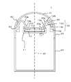
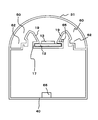
- FIG. 3 is a cross-sectional view of the straight tube type light emitting diode illuminating device according to the first embodiment taken along a cross-sectional line AA shown in FIG.
- the light emitting diode type illumination device includes an LED illumination tube including a total luminous flux transmission plate arranged in the light irradiation direction; LED element as a light source disposed on the substrate facing the total luminous flux transmitting plate in the LED illumination tube, A first light reflecting member provided with a condensing reflection surface having a light reflection characteristic disposed on the light emitting side of the LED element; The first light reflecting member is arranged to extend in the light emitting direction symmetrically or asymmetrically with respect to the center line of the LED element, The condensing reflection surface of the first light reflecting member has a light directivity forming surface for giving the light emitted from the LED element light directivity and irradiating the LED illumination tube outside the tube through the total luminous flux transmission plate, A second reflecting member comprising a pseudo LED element forming surface for projecting the pseudo LED element of the LED element, and a light reflecting surface disposed on the illumination tube and having a light reflecting property facing the total luminous flux transmitting plate;
- the second reflecting member comprising
- the first light reflecting member 191 is disposed symmetrically with respect to the center line of the LED element on both sides of the LED element, and the light emitted from the LED element has a light directivity to be connected to the outside of the LED illumination tube. It is provided to extend so as to be irradiated.
- the first light reflecting member 19 is integrally provided on the substrate 17.
- FIG. 4 is a schematic diagram illustrating an optical path of light emitted from a light source that is an LED element in the light-emitting diode type illumination device of FIG.
- the elevation angle of the first reflecting member with respect to the substrate is set to 50 to 75 degrees, preferably 50 to 65 degrees, and the second reflecting member is moved from the end of the first reflecting member.
- the light emitted from the LED element goes straight in the internal space of the first reflecting member from directly below the light source of the LED element.
- the total luminous flux transmission plate preferably has a curved surface.
- the light emitted from the LED element is confined in the light flux confining means provided in the total light flux transmitting plate and / or in the space between the total light flux transmitting plate and the second reflecting member.
- the light emitted from the confined LED element is irradiated outside the tube through the total luminous flux transmitting plate.
- the second reflecting member and / or the total light flux transmitting plate include at least one recess for confining light.
- the light emitted from the LED element through the translucent cover including the total luminous flux transmission plate is preferably irradiated with an irradiation angle: 120 to 180 degrees, a total luminous flux: 2000 to 3000 lm.
- the elevation angle of the first light reflecting plate is changed from 50 degrees to 75 degrees, the distance between the arrangement end of the LED element and the first light reflecting plate is set to 0.1 to 5.0 mm, and the height of the first light reflecting plate is set to LED.
- the width By setting the width to 5 times or more of the element width, preferably 10 mm to 20 mm, it is possible to eliminate the loss of light amount over a wide irradiation angle, and to improve the illuminance and PPFD.
- the illuminance irradiated by the LED light source is preferably 1.5 to 2.0 times. Note that the elevation angle of the first reflecting member with respect to the substrate, the distance between the LED element end portion and the reflecting plate, and the height of the reflecting plate may be varied according to the size of the LED lighting device such as the diameter.
- FIG. 5A shows the total luminous flux transmission plate from the state in which the light emitted from the LED element is confined in the total luminous flux transmission plate as the light confinement means and / or in the space between the total luminous flux transmission plate and the second reflecting member. The figure irradiated through is shown.
- FIG. 5B shows a view irradiated from an unconfined state, respectively. From the figure, it can be seen that the light irradiated through the total luminous flux transmission plate from the state where the light is confined is irradiated almost uniformly over the entire total luminous flux transmission plate.
- the light irradiated from the unconfined state has a bright central area where the LED elements are arranged, and its peripheral area has lower illuminance than the central area, and the central area and the peripheral area of the total luminous flux transmission plate. And the illuminance looks uneven.
- FIG. 5A shows a color temperature of 3000K, total light transmittance: 60 to 70% (ML7500 series manufactured by Teijin Ltd .; milk white cover), and
- FIG. 5B shows a color temperature of 3000K, total light transmittance: 89% (Teijin Chemicals).
- a total luminous flux transmission plate of MN4800 series (transparent cover) clear plate) was used.
- FIG. 6 shows that the pseudo LED element 13a of the LED element 13 mounted on the substrate is first reflected when the LED element is viewed from the direction in which the light emitted from the LED element disposed on the substrate is irradiated.
- the photograph seen on the pseudo LED formation surface of a member is shown.
- the illuminance of the LED element at that time is preferably 30 to 80 lx / w.
- the pseudo LED element forming surface is defined and formed by the total reflectance of the first light reflecting surface, the elevation angle of the first light reflecting member, and the distance between the LED element installation end and the light reflecting surface of the reflecting member. It is preferable.
- the total luminous flux transmission plate preferably has a total luminous flux transmittance of 95% or more.
- the total reflectance of the reflecting member is preferably defined by 80% or more.
- the light reflecting surface of the first light reflecting member according to the present invention preferably has different total reflectance and / or shape between the light directivity forming surface and the pseudo LED element forming surface.
- the pseudo LED element forming surface varies at least one of the total reflectance of the light reflecting surface, the elevation angle of the first light reflecting member, and the distance between the LED element end and the reflecting member. It is preferable that the number of the pseudo LED elements projected on the pseudo LED forming surface is varied and projected.
- FIG. 7 shows a schematic view in which the light reflecting member 19 is attached to the cylindrical tube body 10.
- the cylindrical tubular body 10 includes a locking portion that locks the upper end portion 71 of the light reflecting member 19.
- the locking portion includes a first locking portion and a second locking portion 72 for locking the upper end portion 71 of the light reflecting member 19 to the cylindrical tubular body 10.
- the upper end portion 71 of the light reflecting member 19 is sandwiched between the first locking portion 70 and the second locking portion 72.
- the upper end portion 71 of the light reflecting member 19 only needs to be locked to the first locking portion 70 or 72.
- the cylindrical tube body 10 includes a locking portion that locks the substrate support member 17. Both ends of the substrate support member 17 are held between the third locking portion 74 and the fourth locking portion 76.
- the substrate support member 17 only needs to be locked to the fourth locking portion 74 or 76.
- the substrate support member 17 and the light reflecting member 19 are integrally formed. However, the substrate supporting member 17 and the light reflecting member 19 are confined in the light reflecting portion light confining space 62, and the confined light is irradiated from the total light flux transmitting plate 31 to the outside of the tube. It is preferred that The material 19 and the substrate support member 17 may be configured separately.
- the light reflecting member 19 and the substrate support member 17 are fixed to each other with screws or an adhesive.
- the light reflecting member 19 including the substrate support member 17 may be detachably attached from the locking portion.
- the light reflecting member 19 and the substrate support member 17 may be separately attached to the locking portion so as to be removable.
- the light directivity forming surface and the pseudo LED forming surface have different shapes.
- the light directivity forming surface and the pseudo LED forming surface have at least a part of a shape other than a straight line and a straight line, for example, a curved surface, an unevenness, a saw shape, a combination of these shapes, and the pitch can be changed by these shapes. Alternatively, it may be formed in combination.
- the light directivity forming surface and the pseudo LED forming surface may have the same shape.
- the total reflectance may be different between the light directivity forming surface and the pseudo LED forming surface.
- the total reflectance may be different in the range of 80% to 95%.
- the first light reflecting member includes a light directivity forming surface for directing light emitted from the LED element to irradiate the LED illumination tube outside the tube, and a condensing reflection surface on the side facing the LED element. And a pseudo LED element forming surface for projecting the pseudo LED element of the mounted LED element.
- the pseudo LED element forming surface may form a light directivity forming surface.
- the light-emitting diode type illumination device When the light-emitting diode type illumination device is a straight tube type light-emitting diode type illumination lamp, it has a length and a diameter that can replace a conventional fluorescent tube in a fluorescent lamp fixture.
- the total length of the straight tube type light emitting diode type illumination lamp is the same as that of a conventional straight tube type fluorescent lamp, and can be appropriately set to, for example, 300 mm to 2400 mm depending on the application.
- the diameter is substantially the same as that of a conventional straight tube fluorescent lamp, and it is preferable that the overall shape and appearance are substantially the same as those of a straight tube fluorescent lamp.
- the tube of the light emitting diode illumination device is a member having a substantially semi-cylindrical cross-sectional shape.
- the tube of the light emitting diode illumination device can be formed of a material such as glass or synthetic resin, for example.
- a member integrally formed so as to be a long semi-cylinder made of a material having predetermined elasticity such as polycarbonate resin may be used.
- the whole or a part of the tube of the light emitting diode type illumination lamp has translucency, and may be formed of a transparent, translucent, and colored transparent material as long as it can transmit light.
- an electronic component such as an AC power source for driving the light emitting diode type illumination device is provided in the LED illumination tube, and is mounted on the substrate in a position and wiring manner that does not interfere with the light emitted from the LED light source. It is preferable.
- the illuminance projected by the pseudo LED element is not limited as long as the LLD element emits light, but preferably includes at least 30 lx / w to 80 lx / w.
- the LED illuminance was measured by applying an alternating current of 100 V 50 Hz to the light emitting diode illumination device.
- a general form AA illuminance form defined in JIS C1609 was used.
- the measurement distance was set to 1 m between the front surface of the light source of the LED element and the illuminance-type measurement reference plane.
- the light source was measured by lighting vertically downward.
- the measurement results are as follows.
- the power consumption (W) of the LED element is 19.5W. Measurement result 1; 724 (lx) 37.1 lx / w Measurement result 1; 870 (lx) 44.6 lx / w Measurement result 1; 1556 (lx) 79.8 lx / w
- a power source that is a driving device for driving an LED element as a light source is (1) a single power source of 5V, 12V, or 24V, or (2) at least a forward voltage of 1.5V to 4.5V, or (3 ) It is preferable to drive with any voltage of 90V to 240V.
- the power source is preferably disposed at a position where it does not interfere with light emitted from the LED element.
- a power source for driving the LED element is disposed on the bottom of the tube below the substrate on which the LED element is mounted.
- a power source for driving the LED element is mounted on the substrate on the opposite side of the first light reflecting member facing the LED element.
- the LED element is a surface-mounted white LED that emits white light when the above-described predetermined voltage is applied. It is preferable that the LED elements are arranged at regular intervals so as to form a line along the longitudinal direction of the substrate 12 at the center position in the width direction on the surface side of the substrate. The LED elements may be arranged in a plurality of rows along the longitudinal direction of the substrate 12.
- the reflective member preferably includes a heat sink member such as an Al material.
- a heat sink member such as an Al material.
- the distance between the heat sink part directly under the substrate on which the LED element is mounted and the heat sink part touched by the human body is set to be two to three times longer than the conventional heat sink. This improves the heat conduction efficiency and enhances the heat dissipation effect of the heat generated when the LED element is energized.
- the heat sink structure directly under the substrate on which the LED element is mounted is not a semi-cylindrical structure and the distance from the LED element directly below and the heat sink that touches the human body is short, but the distance from directly below the LED element to the heat sink that touches the human body is increased. Therefore, it is preferable to adopt an M-type structure to increase the heat conduction efficiency and further promote heat dissipation.
- an M-shaped heat sink (cross section) structure that condenses and reflects light at a constant angle reflects light emitted from the LED element, directs it in a predetermined direction, and improves illuminance.
- the heat sink (cross section) of the M-shaped structure it is preferable to treat the heat sink surface on the LED element side with silver coating, plating or chrome treatment with high reflection efficiency.
- the heat sink cover be of a diffusion type or a prism type.
- the light emitting diode illumination device 1 has a length and a diameter that can replace a conventional fluorescent light tube in a fluorescent lamp fixture.
- the total length of the light emitting diode illumination device is the same as that of a conventional straight tube fluorescent lamp, and can be appropriately set to, for example, 300 mm, 450 mm, 600 mm, 900 mm, 1200 mm, 1800 mm, 2400 mm, etc. according to the application.
- the tube diameter of the light-emitting diode illuminating device is substantially the same as that of a conventional straight tube fluorescent lamp, and preferably has the same outer shape and appearance as a straight tube fluorescent lamp as a whole.
- the light-emitting diode illuminating device 1 is provided in a cylindrical tube body 10 including a translucent cover 31 and a tube member 15 including a total luminous flux transmission plate, and the cylindrical tube body 10.
- the LED element 13 as the light source, the substrate 12 on which the LED element 13 is mounted, the substrate support member 17, the light reflecting member 19, the LED controller 22, and the end cap 50 are provided.
- the light reflecting member 19 includes a first light reflecting member 191, a second light reflecting member 193, and a third light reflecting member 195.
- the tube member 15, the substrate support member 17, the first light reflecting member 191, the second light reflecting member 193, and the third light reflecting member 195 are made of a heat-resistant material such as aluminum, copper, or plastic.
- the substrate support member 17 and the first light reflecting member 191 are preferably formed integrally. Further, it is preferable that the first light reflecting member 191, the second light reflecting member 193, and the third light reflecting member 195 are integrally formed. Furthermore, it is preferable that the substrate support member 17, the first light reflecting member 191, the second light reflecting member 193, and the third light reflecting member 195 are integrally formed. If plastic is used for these members 17, 191, 193, 195, these members can be easily formed integrally. The substrate support member 17, the first light reflecting member 191, the second light reflecting member 193, and the third light reflecting member 195 are individually formed, and then these members are selected and bonded with an adhesive, screws, or the like. May be.
- a heat sink for these members 15, 17, 191, 193, and 195, a high heat dissipation effect can be obtained.
- the heat sink is made of aluminum, the heat of the part touched by the human body is kept at a safe temperature, for example, It can be 40 degreeC.
- the heat sink material is generally aluminum or copper, which is excellent in heat conduction efficiency.
- the heat sink surface temperature which is the biggest problem of LED straight tubes (fluorescent lamp type) and LEDs, can be kept at a safe temperature (about 40 ° C.) even when touched by a human body.
- the illuminance can be equivalent to or better than that of a fluorescent lamp.
- the substrate 12 is accommodated and supported in a longitudinal internal space (closed space) of the substrate support member 17.
- the LED element 13 is disposed in a stripe-like opening formed on the side of the translucent cover 31 of the substrate support member 17 with the light emitting surface facing the translucent cover 31.
- the substrate 12 preferably has conductivity.
- substrate support member 17 receives the heat
- the first light reflecting member 191 is extended from one end serving as a coupling portion with the substrate support member 17 toward the translucent cover 31.
- the LED element 13 is disposed on the center line 61 of the translucent cover 31 along the cross section in the cross section of the closed space of the light emitting diode lighting device 1.
- the translucent cover 31 is preferably a total luminous flux transmission plate having a total luminous flux transmittance of 95% or more.
- the total luminous flux transmission plate preferably has a total luminous flux transmittance of 95 (%) or more.
- As the translucent cover 33 a resin-made ML series that is a high diffusion type manufactured by Teijin Limited was used.
- the total luminous flux transmittance (%) is represented by the total luminous flux when the test piece is placed / total luminous flux when the test piece is not placed ⁇ 100.
- the LED elements 13 mounted on the substrate 12 may be arranged in one row or in a plurality of rows with a predetermined interval in the longitudinal direction of the substrate. As shown in FIG. 2, a plurality of LED elements 13 are mounted on the substrate 12 at equal intervals along the longitudinal direction.
- An LED controller 21 is disposed at the end of the substrate 12.
- the first light reflecting member 191 is disposed symmetrically or asymmetrically with respect to the center line of the LED element on both sides of the LED element with a distance (S) from the LED element, and is directed to the light emitted from the LED element. It is provided to extend so that light is emitted from the LED illumination tube to the outside of the tube.
- the length of the first reflecting member is preferably 5 times or more the width of the LED element, preferably about 10 mm to 20 mm from the substrate.
- the first light reflecting member 191 preferably includes a condensing reflection surface 19a on the LED element side.
- the condensing / reflecting surface 19a preferably includes a pseudo LED element forming surface 20b that reflects a pseudo LED element of the LED element mounted on the light directing surface 20a and the light reflecting surface facing the LED element.
- the distance (S) between the LED element end and the condensing reflection surface of the first reflecting member 19 is 0.1 mm to 5.0 mm, preferably 0.5 mm to 2.0 mm. It is preferable that the elevation angle ⁇ of 19 is defined as 50 to 75 degrees, preferably 50 to 65 degrees, and the total reflectance of the reflecting member is set to 80% or more. The interval may be zero if an electrical insulating material is provided on a part of the condensing reflection surface.
- FIG. 6 shows a diagram in which the pseudo LED element is projected on the condensing reflection surface 19a of the first reflecting member 19 when the lower side of the LED element mounted on the substrate is viewed from the irradiation direction of the LED element.
- the end cap 50 is fitted into two end portions of a tubular structure constituted by the tubular member 15 and the translucent bar 31.
- the end cap 50 is provided with a power supply pin 51.
- the first light reflecting member 191 includes a condensing / reflecting surface 19a at an extending portion 23 that extends toward the translucent cover 31 in a direction in which light emitted from the LED element mounted on the substrate travels.
- the extending portion 23 is disposed symmetrically or asymmetrically with respect to the center line of the LED element on both sides of the LED element in a direction in which light emitted from the LED element mounted on the substrate travels.
- the extending part 23 is preferably arranged in a posture in which the light from the light emitting element 13 is directed to the translucent cover 31.
- the first light reflecting member 19 extends along a curved shape of the first light reflecting member 191 extending at a predetermined elevation angle; an angle of 50 to 75 degrees toward the translucent cover 31 and the translucent cover 31.
- a second light reflecting member 193 that is bent and a third light reflecting member 195 that connects the first light reflecting member 191 and the second light reflecting member 193 are provided.
- the light reflecting member 19 is not limited to the structure of the first light reflecting member 191, the second light reflecting member 193, and the third light reflecting member 195, and may be configured in a multistage structure by connecting the light reflecting members.
- the second light reflecting member 193 and the third light reflecting member 195 preferably include light reflecting surfaces 193a and 195a having light reflecting characteristics on the side facing the translucent cover 31, respectively.
- the pseudo LED element forming surface is defined by at least one of the total reflectance of the light reflecting surface, the elevation angle of the first light reflecting member, and the distance between the LED element installation end and the light reflecting surface of the previous reflecting member. Preferably it is formed.
- the total luminous flux transmission plate preferably has a total luminous flux transmittance of 95% or more.
- the total reflectance of the reflecting member is preferably defined by 80% or more.
- the total reflectance of the condensing reflection surface of the first light reflecting member is 80% or more.
- silver plating, silver coating, chrome plating, or the like is preferably applied to the condensing reflection surface 19a. The illuminance at this time is determined based on the light brightness theorem that “the brightness is inversely proportional to the square of the distance between the light source and the irradiation surface”.
- the light emitted from the LED element irradiates the outside of the tube through the total luminous flux transmission plate 31 through the light reflecting member 19.
- the light emitted from the LED element is arranged corresponding to the light reflecting surface 193a of the second light reflecting member 193 when irradiating the tube through the total light flux transmitting plate 31 via the first light reflecting member 191. It is confined in the provided total light flux transmission plate 31 and / or confined in the light confinement path 60 formed between the total light flux transmission plate 31 and the second light reflecting member 193, and further provided in the light confinement path 60. It is preferable that the light confined and confined in the confined light confinement space 62 is irradiated from the total light flux transmission plate 31 to the outside of the tube.
- the light emitted from the LED element is transmitted through a light reflecting member, preferably the first light reflecting member 191, and is confined in the light confining space 62, and the confined light is transmitted from the total light flux transmitting plate 31 to the tubular body. It is preferable to irradiate outside.
- the first light reflecting member 191 has an elevation angle with respect to the substrate; 50 From 75 to 75 degrees, preferably from 50 to 65 degrees, the distance (S) between the LED element end and the first light reflecting member: 0.5 to 5.0 mm, the height of the reflector; the width of the LED element It is preferably set to 5 times or more, preferably 10 to 20 mm.
- the light beam is confined in the total light beam transmission plate 31 disposed corresponding to the reflection surface of the second light reflection member 20, and / or in the space between the total light beam transmission plate and the second light reflection member. It is preferable that the confined light confined in the formed light confinement path 60 is radiated from the total luminous flux transmission plate 31 to the outside of the tube.
- the light confinement path 60 formed in the space between the total light flux transmitting plate and the second light reflecting member is preferably formed by fitting the end of the second light reflecting member to the total light flux transmitting plate.
- the second reflecting member and / or the total light flux transmitting plate preferably includes at least one light confinement recess 62.
- the light emitted from the LED element to the outside of the tube through the total luminous flux transmitting plate is irradiated at an irradiation angle: 120 degrees to 180 degrees, a total luminous flux total luminous flux: 2000 to 3000 lm.
- the pseudo LED is preferably projected on the first light reflecting member.
- the translucent cover 31 can be passed.
- the treatment for increasing the reflection efficiency of the present embodiment is silver coating, silver plating, or a coating equivalent thereto.
- the total reflectance can be improved to 90%.
- the light-emitting diode illumination device 1 uses a light reflecting member having the shape shown in FIGS. 2 and 3 so that the distance between the LED element and the outer peripheral surface of the light-emitting diode illumination device 1 (the part touched by the human body) is a conventional structure. Can be made longer (more than twice as long).
- the illuminance distribution can be wide angle (140 degrees or more), and the performance (illuminance and light distribution) of the conventional fluorescent lamp is 50% of the power consumption of the fluorescent lamp.
- the power consumption can be reduced to about 12 to 13 compared to the fluorescent lamp, and the illuminance / PPFD can be increased to 2 to 3 times (compared to the conventional LED). Contributes to safety and security without generating high heat like fluorescent tubes.
- pipe type light emitting diode type illumination lamp 1 can be 500 g or less.
- FIG. 8 is a cross section of the straight tube type light emitting diode illumination device of the present embodiment taken along the cross-sectional line AA shown in FIG.
- the condensing reflection surface 19 a on the LED element side of the first light reflecting member 191 constituting the light reflecting member 19 has light reflecting characteristics and is concave with respect to the center line 61.
- the curvature of the curved surface is appropriately determined according to the required optical characteristics.
- the condensing reflection surface 19 a may be formed in a curved surface that is convex toward the center line 61.
- the curvature of the curved surface is appropriately determined according to the required light directivity.
- FIG. 9 is a cross-sectional view of the light-emitting diode illuminating device of the present embodiment taken along a cross-sectional line AA shown in FIG.
- the whole or a part of the condensing reflection surface 219a on the LED element 13 side of the first light reflection member 191 has light reflection characteristics, and a large number of irregularities are formed.
- the shape, size, interval, and number of the unevenness are appropriately determined according to required optical characteristics.
- FIG. 10 is a cross section of the straight tube type light emitting diode illumination device of the present embodiment taken along the cross-sectional line AA shown in FIG.
- the condensing reflection surface 19 a on the LED element 13 side of the first light reflecting member 19 is formed only on one of the center lines 61.
- the light emitting diode type illumination device of the present embodiment is disposed at the end when a plurality of light emitting diode type illumination lamps are installed in parallel. In the present embodiment, the amount of light can be increased in one direction.
- Fifth embodiment is a cross section of the straight tube type light emitting diode illumination device of the present embodiment taken along the cross-sectional line AA shown in FIG.
- the condensing reflection surface 19 a on the LED element 13 side of the first light reflecting member 19 is formed only on one of the center lines 61.
- the light emitting diode type illumination device of the present embodiment is disposed at the end when a plurality of light emitting diode type illumination lamps are installed in parallel. In
- FIG. 11 is a cross-sectional view of the light-emitting diode type illumination device of the present embodiment taken along the cross-sectional line AA shown in FIG.
- a space is formed between the light reflecting surface 293a of the second light reflecting member 293 facing the light transmitting cover 31 of the first light reflecting member 191 and the light transmitting cover 31.
- the light reflecting surface 293a of the second light reflecting member 293 may be provided in contact with the inner surface of the translucent cover 31, as shown in the drawing. According to the said structure, it can suppress effectively that water flows in from the mounting part 83 in which the tubular member 33 and the translucent cover 31 are joined at the time of mounting
- a frame member 40 that forms a space for accommodating the power supply 65 of the light emitting diode 13 is provided.
- the drive apparatus provided with a power supply is arrange
- the power supply 50 is installed at the position of the bottom of the frame member 40. Further, the power source 50 may be disposed on the base portion 17 in the space of the elevation angle ⁇ of the reflecting member 191.
- a forward voltage for driving the LED element of the light emitting diode type illumination device at least 1.5V to 4.5V.
- the forward voltage of one chip of the LED element emitting white light is, for example, 1.8V to 2.3V, 2.4V to 3.3V, 2.8V to 3.2V, 3.2V to 3.6V. 3.6V to 4.03V.
- the LED lighting device of this example used a universal power source. 100 LED elements (chips) were connected.
- the AC type input voltage (AC) is 20 W, 90 V to 264 Vac.
- the power source can be driven using a battery.
- the LED lighting device can be driven by a single power source such as 5V.
- the driving power source may be a battery; 1.5V ⁇ n. Even if such a power source is used, the light emitted from the LED element has directivity, and the light directing surface 20b for irradiating the light from the LED illumination tube to the outside of the tube, and the side facing the LED element A pseudo LED element forming surface 20a for projecting the pseudo LED element of the mounted LED element on the condensing reflection surface can be provided.
- a driving device such as an AC power source is preferably provided in the LED illumination tube and disposed at a position that does not interfere with light emitted from the LED light source.
- electronic parts such as a power source other than the LED light source, all or a part thereof may be arranged on the back surface side instead of the front surface side of the substrate. Can be arranged on the back side, and the internal space on the surface side of the substrate can be widened.
- a driving device such as an AC power source is preferably disposed below the substrate on which the LED elements in the LED lighting tube are mounted, or on the back side of the condensing reflection surface of the reflecting member.
- a forward voltage for driving the LED element of the light emitting diode type lighting device at least 1.5V to 4.5V is applied to the LED element to drive the light emitting diode type lighting device, and the LED element mounted on the substrate
- the pseudo LED element is displayed on the pseudo LED formation surface.
- the pseudo LED element preferably projects the pseudo LED element on the pseudo LED formation surface if the LED element emits light.
- the driving voltage is preferably driven by a single power source. Seventh embodiment
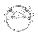
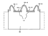
- two light emitting diodes 13-1 and 13-2 may be provided in a direction orthogonal to the longitudinal direction.
- the number of light emitting diodes 13 provided in the orthogonal direction may be three or more.
- the light emitting diode 13-1 is sandwiched between the light reflecting member 19-1 and the light reflecting member 19-2, and the light reflecting member 19-1 and the light reflecting member 19-2 on the light emitting diode 13a side have reflection characteristics.
- the light emitting diode 13-2 is sandwiched between the light reflecting member 19-2 and the light reflecting member 19-3, and the light reflecting member 19-2 and the light reflecting member 19-3 on the light emitting diode 13a side have reflection characteristics.
- the two light emitting diodes 13-1 and 13-2 are arranged so as to be inclined so as to emit light in different directions toward the outside of the illumination device.
- two light emitting diodes 13-1 and 13-2 may be provided in a direction orthogonal to the longitudinal direction.
- the number of light emitting diodes 13 provided in the orthogonal direction may be three or more.
- the light emitting diode 13-1 is sandwiched between the light reflecting member 19-1 and the light reflecting member 19-2, and the light reflecting member 19-1 and the light reflecting member 19-2 on the light emitting diode 13a side have reflection characteristics. Yes.
- the light emitting diode 13-2 is sandwiched between the light reflecting member 19-2 and the light reflecting member 19-3, and the light reflecting member 19-2 and the light reflecting member 19-3 on the light emitting diode 13a side have reflection characteristics. Yes.
- the light-emitting diode illumination device according to the present invention is preferably a straight tube light-emitting diode illumination device.
- the light emitting diode type illumination device according to the present invention may be used for a light source of an electronic device, for example, a backlight of a liquid crystal device.
- the present invention is applicable to light emitting diode type illumination lamps, electronic devices, plant factories, and LED signboards.
Landscapes
- Engineering & Computer Science (AREA)
- General Engineering & Computer Science (AREA)
- Physics & Mathematics (AREA)
- Microelectronics & Electronic Packaging (AREA)
- Optics & Photonics (AREA)
- Non-Portable Lighting Devices Or Systems Thereof (AREA)
Abstract
Description
特許文献2 特開2013-219004号公報
前記LED照明管内に前記全光束透過板に対向して基板に配置されたLED素子と、
該LED素子の発光側に配設された光反射特性を有する集光反射面を備える光反射部材とを有し、記光反射部材は、前記LED素子の中心線に対して対称又は非対称に光の照射方向に向けて延出して配設され、
前記光反射部材の集光反射面は、前記LED素子から発光した光に光指向性を持たせてLED照明管から全光束透過板を通して管外に照射させるための光指向形成面と、
前記LED素子から発光した光を前記全光束透過板に、及び又は前記全光束透過板と前記光反射部材との間の空間に閉じ込めて該全光束透過板を通して前記管外に照射するための光閉じ込め手段とを備える、
発光ダイオード式照明装置。
前記LED照明管内に前記全光束透過板に対向して基板に配置されたLED素子と、
該LED素子の発光側に配設された光反射特性を有する集光反射面を備える光反射部材とを有し、
前記光反射部材は、前記LED素子の中心線に対して対称又は非対称に光の照射方向に向けて延出して配設され、
前記光反射部材の集光反射面は、前記LED素子から発光した光に光指向性を持たせてLED照明管から全光束透過板を通して管外に照射させるための光指向形成面と、
前記LED素子の擬似LED素子を映し出すための擬似LED素子形成面を備え、
前記基板に配設されたLED素子から照射される光の方向から該LED素子を見た際に、前記擬似LED形成面に前記基板に配設されたLED素子の擬似LED素子が映って見える発光ダイオード式照明装置。
前記LED照明管内に前記全光束透過板に対向して基板に配置されたLED素子と、
該LED素子の発光側に配設された光反射特性を有する集光反射面を備える光反射部材とを有し、
該光反射部材は、第1光反射部材と第2光反射部材とを備え、
該第1光反射部材は、該LED素子の発光側に配設された光反射特性を有する集光反射面を備え、
前記第1光反射部材は、前記LED素子の中心線に対して対称又は非対称に光の照射方向に向けて延出して配設され、
前記第1光反射部材の集光反射面は、前記LED素子から発光した光に光指向性を持たせてLED照明管から全光束透過板を通して管外に照射させるための光指向形成面と、
前記LED素子の擬似LED素子を映し出すための擬似LED素子形成面を備え、
前記照明管に配設され全光束透過板に対向して光反射特性を有する光反射面を備える第2光反射部材と、
前記第2反射部材は、第1反射部材の終端から全光束透過板の形状に沿って外方に向かって広角方向に配設され、
前記LED素子から発光した光を前記全光束透過板に、及び又は前記全光束透過板と前記光反射部材との間の空間に閉じ込めて該全光束透過板を通して前記管外に照射するための光閉じ込め手段とを備え、
該光が照明管外へ照射されるに伴い前記基板に搭載された擬似LEDが前記擬似LED素子形成面に映し出される発光ダイオード式照明装置。
前記LED照明管内に前記全光束透過板に対向して基板に配置されたLED素子と、
該LED素子の発光側に配設された光反射特性を有する集光反射面を備える光反射部材とを有し、
該光反射部材は、第1光反射部材と第2光反射部材とを備え、
該第1光反射部材は、該LED素子の発光側に配設された光反射特性を有する集光反射面を備え、
前記第1光反射部材は、前記LED素子の中心線に対して対称又は非対象に光の照射方向に向けて延出して配設され、
前記第1光反射部材の集光反射面は、前記LED素子から発光した光に光指向性を持たせてLED照明管から全光束透過板を通して管外に照射させるための光指向形成面と、
前記LED素子の擬似LED素子を映し出すための擬似LED素子形成面を備え、
前記照明管に配設され全光束透過板に対向して光反射特性を有する光反射面を備える第2反射部材を有し、
前記第2反射部材は、第1反射部材の終端から全光束透過板の形状に沿って外方に向かって広角方向に配設され、
前記LED素子から発光した光を前記全光束透過板に、及び又は前記全光束透過板と前記反射部材との間の空間に閉じ込めて該全光束透過板を通して前記管外に照射するための光閉じ込め手段とを備え、
前記基板に配設されたLED素子から照射される光の方向から該LED素子を見た際に、前記擬似LED形成面に前記基板に配設されたLED素子の擬似LED素子が映って見える発光ダイオード式照明装置。
以下、本発明に係る発光ダイオード式照明装置、特に直管形発光ダイオード式照明装置を以下に詳述する。図1は、本発明に係る発光ダイオード式照明装置を示す概略図である。図2は、図1に示す直管形発光ダイオード照明装置の分解斜視図である。図3は、図1に示す断面線AーAにおける第1実施形態に係る直管形発光ダイオード照明装置の断面図である。
前記LED照明管内に前記全光束透過板に対向して基板に配置された光源としてのLED素子と、
該LED素子の発光側に配設された光反射特性を有する集光反射面を備える第1光反射部材と、
前記第1光反射部材は、前記LED素子の中心線に対して対称又は非対称に光の発光方向に向けて延出して配設され、
前記第1光反射部材の集光反射面は、前記LED素子から発光した光に光指向性を持たせてLED照明管から全光束透過板を通して管外に照射させるための光指向形成面と、前記LED素子の擬似LED素子を映し出すための擬似LED素子形成面を備え、前記照明管に配設され全光束透過板に対向して光反射特性を有する光反射面を備える第2反射部材と、前記第2反射部材は、第1反射部材の終端から全光束透過板の形状に沿って外方に向かって広角方向に配設され、を備えることが好ましい。
一方閉じ込められてない状態から照射された光は、LED素子が配設されたほほ中央の領域が明るく、その周辺領域は、中央に比べて照度が低く、全光束透過板の中央領域と周辺領域とで照度が不均一に見える。
ここで、図5Aは、色温度3000K、全光線透過率;60~70%(帝人社製ML7500シリーズ;乳白カバー)を、図5Bは、色温度3000K、全光線透過率;89%(帝人化成社製MN4800シリーズ;透明カバー)クリア板)の全光束透過板を使用した。
その時のLED素子の照度は、30~80lx/wを備えることが好ましい。
反射部材の全反射率は、80%以上により規定されることが好ましい。
全反射率は、80%~95%の範囲で異にしてもよい。
測定結果は、以下の通りである。LED素子の消費電力(W)は、19.5Wである。
測定結果1;724(lx) 37.1 lx/w
測定結果1;870(lx) 44.6 lx/w
測定結果1;1556(lx)79.8 lx/w
本実施形態の直管形発光ダイオード式照明灯では、LED素子が実装される基板直下のヒートシンク部分と、人体が触れるヒートシンク部分との距離を従来のヒートシンクの2~3倍以上の長さにすることにより熱伝導効率が良くなり、LED素子が通電される際に発生する熱の放熱効果を高める。
第1光反射部材191は、基板支持部材17との結合部となる一端から透光性カバー31に向けて延びて配説される。
前記反射部材の全反射率は、80%以上により規定されることが好ましい。
以下、第1反射部材の集光反射面の形状の他の実施形態を説明する。
第2実施形態
図に示すように、本実施形態では、光反射部材19を構成する第1光反射部材191のLED素子側の集光反射面19aは、光反射特性を有し、中心線61に対して凹状の曲面になっている、当該曲面の曲率は、要求される光特性に応じて適宜決定される。集光反射面19aは、中心線61に向けて凸になる曲面に形成してもよい。当該曲面の曲率は、要求される光指向性に応じて適宜決定される。
第3実施形態
図に示すように、本実施形態では、第1光反射部材191のLED素子13側の集光反射面219aの全体あるいは一部は、光反射特性を有し、多数の凹凸が形成されている。当該凹凸の形状、大きさ、間隔、数は要求される光特性に応じて適宜決定されることが好ましい。
第4実施形態
図に示すように、本実施形態では、第1光反射部材19のLED素子13側の集光反射面19aは、中心線61の一方にのみに形成される。
本実施形態の発光ダイオード式照明装置が、複数の発光ダイオード式照明灯を並列に並べて設置した場合に端部に配置される。本実施形態では、一方向に光量を高めることができる。
第5実施形態
上述した第1本実施形態では、第1光反射部材191の透光性カバー31と対向する第2光反射部材293の光反射面293aと、透光性カバー31との間に空間を形成する場合を例示したが、本実施形態では、該図に示すように、第2光反射部材293の光反射面293aが、透光性カバー31の内面と接触して設けられてもよい。当該構成によれば、管体部材33と透光性カバー31とが装着時に接合される装着部83から水が流入することを効果的に抑制でき、屋外灯として利用できる。
第6実施形態
この時のアノードとカソード間の電圧が、順方向電圧である。
第7実施形態
本発明に係る発光ダイオード式照明装置は、電子装置の光源、例えば液晶装置のバックライトに使用してもよい。
10 円筒状管体
12 基板
13 LED素子
13a 疑似LED素子
15 管体部材
16 中心線
17 基板支持部材
19 光反射部材
191 第1光反射部材
19a 集光反射面
193 第2光反射部材
193a 光反射面
195 第3光反射部材
195a 光反射面
20a 光指向形成面
20b 疑似LED形成面
23 第1光反射部材の延出部
31 透光性カバー
50 端部キャップ
60 光閉込め路
62 光閉込め凹所
65 電源
70 第1係止部
72 第2係止部
74 第3係止部
76第4係止部
Claims (21)
- 光の照射方向に配設された全光束透過板を備えるLED照明管と、
前記LED照明管内に前記全光束透過板に対向して基板に配置されたLED素子と、
該LED素子の発光側に配設された光反射特性を有する集光反射面を備える光反射部材と
を有し、
前記光反射部材は、前記LED素子の中心線に対して対称又は非対称に光の照射方向に向けて延出して配設され、
前記光反射部材の集光反射面は、
前記LED素子から発光した光に光指向性を持たせてLED照明管から全光束透過板を通して管外に照射させるための光指向形成面と、
前記LED素子から発光した光を前記全光束透過板に、及び又は前記全光束透過板と前記光反射部材との間の空間に閉じ込めて該全光束透過板を通して前記管外に照射するための光閉じ込め手段とを備える、
発光ダイオード式照明装置。 - 光の照射方向に配設された全光束透過板を備えるLED照明管と、
前記LED照明管内に前記全光束透過板に対向して基板に配置されたLED素子と、
該LED素子の発光側に配設された光反射特性を有する集光反射面を備える光反射部材と
を有し、
前記光反射部材は、前記LED素子の中心線に対して対称又は非対称に光の照射方向に向けて延出して配設され、
前記光反射部材の集光反射面は、
前記LED素子から発光した光に光指向性を持たせてLED照明管から全光束透過板を通して管外に照射させるための光指向形成面と、
前記LED素子の擬似LED素子を映し出すための擬似LED素子形成面を備え、
前記基板に配設されたLED素子から照射される光の方向から該LED素子を見た際に、前記擬似LED形成面に前記基板に配設されたLED素子の擬似LED素子が映って見える発光ダイオード式照明装置。 - 光の照射方向に配設された全光束透過板を備えるLED照明管と、
前記LED照明管内に前記全光束透過板に対向して基板に配置されたLED素子と、
該LED素子の発光側に配設された光反射特性を有する集光反射面を備える光反射部材と
を有し、
該光反射部材は、第1光反射部材と第2光反射部材とを備え、
該第1光反射部材は、該LED素子の発光側に配設された光反射特性を有する集光反射面を備え、
前記第1光反射部材は、前記LED素子の中心線に対して対称又は非対称に光の照射方向に向けて延出して配設され、
前記第1光反射部材の集光反射面は、
前記LED素子から発光した光に光指向性を持たせてLED照明管から全光束透過板を通して管外に照射させるための光指向形成面と、
前記LED素子の擬似LED素子を映し出すための擬似LED素子形成面を備え、
前記照明管に配設され全光束透過板に対向して光反射特性を有する光反射面を備える第2光反射部材を有し、
前記第2光反射部は、第1反射部材の終端から全光束透過板の形状に沿って外方に向かって広角方向に配設され、
前記LED素子から発光した光を前記全光束透過板に、及び/又は前記全光束透過板と前記光反射部材との間の空間に閉じ込めて該全光束透過板を通して前記管外に照射するための光閉じ込め手段とを備え、
該光が照明管外へ照射されるに伴い前記基板に搭載された擬似LEDが前記擬似LED素子形成面に映し出される発光ダイオード式照明装置。 - 光の照射方向に配設された全光束透過板を備えるLED照明管と、
前記LED照明管内に前記全光束透過板に対向して基板に配置されたLED素子と、
該LED素子の発光側に配設された光反射特性を有する集光反射面を備える光反射部材と
を有し、
該光反射部材は、第1光反射部材と第2光反射部材とを備え、
該第1光反射部材は、該LED素子の発光側に配設された光反射特性を有する集光反射面を備え、
前記第1光反射部材は、前記LED素子の中心線に対して対称又は非対称に光の照射方向に向けて延出して配設され、
前記第1光反射部材の集光反射面は、
前記LED素子から発光した光に光指向性を持たせてLED照明管から全光束透過板を通して管外に照射させるための光指向形成面と、
前記LED素子の擬似LED素子を映し出すための擬似LED素子形成面を備え、
前記照明管に配設され全光束透過板に対向して光反射特性を有する光反射面を備える第2反射部材と、
前記第2反射部材は、第1反射部材の終端から全光束透過板の形状に沿って外方に向かって広角方向に配設され、
前記LED素子から発光した光を前記全光束透過板に、及び/又は前記全光束透過板と前記反射部材との間の空間に閉じ込めて該全光束透過板を通して前記管外に照射するための光閉じ込め手段とを備え、
前記基板に配設されたLED素子から照射される光の方向から該LED素子を見た際に、前記擬似LED形成面に前記基板に配設されたLED素子の擬似LED素子が映って見える発光ダイオード式照明装置。 - 前記発光ダイオード式照明装置は、前記LED素子から発光される光と干渉しない位置に配設されることを特徴とする請求項1から4のいずれか1項記載の発光ダイオード式照明装置。
- 光反射部材を係止する係止部材を備える円筒状管体を有することを特徴とする請求項1から5のいずれか1項記載の発光ダイオード式照明装置。
- 前記光反射部材は、樹脂材から作られている請求項1から5のいずれか1項記載の発光ダイオード式照明装置。
- 前記第1光反射部材と前記2光反射部材とを繋ぐ第3光反射部材を備えることを特徴とする請求項3又は4記載の発光ダイオード式照明装置。
- 前記擬似LED素子形成面は、前記第1反射部材の全反射率と、前記第1反射部材の仰角と、前記LED素子の設置端と前記第1反射部材との間隔によって規定されて形成されることを特徴とする請求項3又は4記載の発光ダイオード式照明装置。
- 前記第1光反射板は、基板に対して仰角が50度から75度に設定されることを特徴とする請求項3又は4記載の発光ダイオード式照明装置。
- 前記LED素子の設置端と前反射部材の集光反射面との間隔長さは、0.1mmから5.0mmに、前記基板表面との仰角は、50度から75度に、かつ前記第1光反射板の高さをLED素子の幅の5倍以上、好ましくは10mmから20mmに設定されることを特徴とする請求項3又は4記載の発光ダイオード式照明装置。
- 前記擬似LED素子形成面は、前記光反射面の全反射率と、前記第1光反射部材の仰角と、前記LED素子の設置端と前記反射部材の集光反射面との間隔長の少なくとも1つを可変することにより、前記擬似LED素子が擬似LED形成面に写し出される個数が可変して写し出されることを特徴とする請求項3又は4記載の発光ダイオード式照明装置。
- 前記第2反射部材、及び/又は前記全光速透過板は、光閉込め用の凹所を備えることを特徴とする請求項3又は4記載の発光ダイオード式照明装置。
- 前記全光速透過板は、全光速透過率95%以上を備えることを特徴とする請求項3又は4記載の発光ダイオード式照明装置。
- 前記光反射部材の全反射率は、80%以上により規定されることを特徴とする請求項3又は4記載の発光ダイオード式照明装置。
- 前記第1反射部材の光反射面は、光指向性形成面と擬似LED素子形成面とで全反射率及び/又は形状を異にすることを特徴とする請求項3又は4記載の発光ダイオード式照明装置。
- 第2光反射部材が、ヒートシンクを備えることを特徴とする請求項1から4のいずれか1項記載の発光ダイオード式照明装置。
- 前記発光ダイオード式照明装置は、直管形発光ダイオード式照明装置であることを特徴とする請求項1から4のいずれか1項記載の発光ダイオード式
照明装置。 - 請求項1から18のいずれか1項記載の発光ダイオード式照明装置を備える電子装置。
- 請求項1から18のいずれか1項記載の発光ダイオード式照明装置を備える植物工場。
- 請求項1から18のいずれか1項記載の発光ダイオード式照明装置を備えるLED看板。
Priority Applications (11)
| Application Number | Priority Date | Filing Date | Title |
|---|---|---|---|
| EP16776698.9A EP3312496A4 (en) | 2015-04-10 | 2016-04-08 | LIGHTING DEVICE FROM THE LIGHT LED TYPE |
| CA2982245A CA2982245A1 (en) | 2015-04-10 | 2016-04-08 | Light-emitting diode type lighting device |
| MX2017013051A MX2017013051A (es) | 2015-04-10 | 2016-04-08 | Dispositivo de iluminación de tipo diodo emisor de luz. |
| AU2016244591A AU2016244591A1 (en) | 2015-04-10 | 2016-04-08 | Light-emitting diode type lighting device |
| CN201680032961.8A CN107709870A (zh) | 2015-04-10 | 2016-04-08 | 发光二极管式照明装置 |
| SG11201708255PA SG11201708255PA (en) | 2015-04-10 | 2016-04-08 | Light-emitting diode type lighting device |
| US15/565,663 US20180149320A1 (en) | 2015-04-10 | 2016-04-08 | Light-emitting diode type lighting device |
| RU2017136552A RU2017136552A (ru) | 2015-04-10 | 2016-04-08 | Светодиодное осветительное устройство |
| BR112017021693A BR112017021693A2 (pt) | 2015-04-10 | 2016-04-08 | dispositivo de iluminação do tipo diodo emissor de luz, dispositivo eletrônico, fábrica de plantas e sinal de led |
| PH12017501839A PH12017501839A1 (en) | 2015-04-10 | 2017-10-06 | Light-emitting diode type lighting device |
| IL254911A IL254911A0 (en) | 2015-04-10 | 2017-10-08 | A light emitting diode type lighting device |
Applications Claiming Priority (14)
| Application Number | Priority Date | Filing Date | Title |
|---|---|---|---|
| JP2015-080787 | 2015-04-10 | ||
| JP2015080787 | 2015-04-10 | ||
| JP2015091148 | 2015-04-28 | ||
| JP2015-091148 | 2015-04-28 | ||
| JP2015-133423 | 2015-07-02 | ||
| JP2015133423 | 2015-07-02 | ||
| JP2015197997 | 2015-09-06 | ||
| JP2015-197997 | 2015-09-06 | ||
| JP2015-190395 | 2015-09-07 | ||
| JP2015190395 | 2015-09-07 | ||
| JP2015246720A JP2017050265A (ja) | 2015-04-28 | 2015-12-01 | 発光ダイオード式照明装置 |
| JP2015-246720 | 2015-12-01 | ||
| JP2015247951A JP2017050266A (ja) | 2015-04-10 | 2015-12-03 | 発光ダイオード式照明装置 |
| JP2015-247951 | 2015-12-03 |
Publications (1)
| Publication Number | Publication Date |
|---|---|
| WO2016163532A1 true WO2016163532A1 (ja) | 2016-10-13 |
Family
ID=57072634
Family Applications (1)
| Application Number | Title | Priority Date | Filing Date |
|---|---|---|---|
| PCT/JP2016/061598 Ceased WO2016163532A1 (ja) | 2015-04-10 | 2016-04-08 | 発光ダイオード式照明装置 |
Country Status (1)
| Country | Link |
|---|---|
| WO (1) | WO2016163532A1 (ja) |
Citations (4)
| Publication number | Priority date | Publication date | Assignee | Title |
|---|---|---|---|---|
| US20120020066A1 (en) * | 2010-07-22 | 2012-01-26 | Hon Hai Precision Industry Co., Ltd. | Led lighting device |
| US20120051039A1 (en) * | 2010-08-24 | 2012-03-01 | Hon Hai Precision Industry Co., Ltd. | Led tube lamp |
| JP2013219004A (ja) * | 2012-04-11 | 2013-10-24 | Mass Technology (Hk) Ltd | 蛍光灯取付具に使用するためのledライト管 |
| JP2014053267A (ja) * | 2012-09-10 | 2014-03-20 | Ricoh Co Ltd | Led直管形ランプ及び照明装置 |
-
2016
- 2016-04-08 WO PCT/JP2016/061598 patent/WO2016163532A1/ja not_active Ceased
Patent Citations (4)
| Publication number | Priority date | Publication date | Assignee | Title |
|---|---|---|---|---|
| US20120020066A1 (en) * | 2010-07-22 | 2012-01-26 | Hon Hai Precision Industry Co., Ltd. | Led lighting device |
| US20120051039A1 (en) * | 2010-08-24 | 2012-03-01 | Hon Hai Precision Industry Co., Ltd. | Led tube lamp |
| JP2013219004A (ja) * | 2012-04-11 | 2013-10-24 | Mass Technology (Hk) Ltd | 蛍光灯取付具に使用するためのledライト管 |
| JP2014053267A (ja) * | 2012-09-10 | 2014-03-20 | Ricoh Co Ltd | Led直管形ランプ及び照明装置 |
Non-Patent Citations (1)
| Title |
|---|
| See also references of EP3312496A4 * |
Similar Documents
| Publication | Publication Date | Title |
|---|---|---|
| US20180149320A1 (en) | Light-emitting diode type lighting device | |
| US11156329B2 (en) | Light-emitting diode-type illumination device | |
| CN102853288A (zh) | 光学元件及具有该光学元件的发光装置 | |
| US20130039070A1 (en) | Lamp with front facing heat sink | |
| KR101132217B1 (ko) | 비대칭 반사 led 조명기구 | |
| JP5717114B1 (ja) | 直管形発光ダイオード式照明灯 | |
| KR20130055467A (ko) | 형광등형 led 조명 기구 장치 | |
| KR102047686B1 (ko) | 조명장치 | |
| US11221112B2 (en) | LED illumination device having light reflecting and transmitting member | |
| KR101803010B1 (ko) | 엘이디 조명기구 | |
| JP6616050B1 (ja) | 浮いた光源を有するランプ | |
| WO2016163532A1 (ja) | 発光ダイオード式照明装置 | |
| JP2017050266A (ja) | 発光ダイオード式照明装置 | |
| JP5888624B2 (ja) | 照明器具 | |
| JP5701675B2 (ja) | カバー及び当該カバーを備えた照明装置 | |
| JPWO2017002960A1 (ja) | 照明装置 | |
| JP2017050265A (ja) | 発光ダイオード式照明装置 | |
| EP3225904B1 (en) | Lighting module and lighting fixture | |
| JP5860132B2 (ja) | カバー及び当該カバーを備えた照明装置 | |
| KR101252689B1 (ko) | 발광다이오드 조명 장치 | |
| KR20100066683A (ko) | Led 조명장치 | |
| JP6081563B2 (ja) | 照明装置 | |
| TWI516719B (zh) | 燈具 | |
| TW201727138A (zh) | 發光二極體式照明裝置 | |
| TW201728852A (zh) | 發光二極體式照明裝置 |
Legal Events
| Date | Code | Title | Description |
|---|---|---|---|
| 121 | Ep: the epo has been informed by wipo that ep was designated in this application |
Ref document number: 16776698 Country of ref document: EP Kind code of ref document: A1 |
|
| WWE | Wipo information: entry into national phase |
Ref document number: 11201708255P Country of ref document: SG Ref document number: 12017501839 Country of ref document: PH |
|
| WWE | Wipo information: entry into national phase |
Ref document number: 254911 Country of ref document: IL |
|
| ENP | Entry into the national phase |
Ref document number: 2982245 Country of ref document: CA |
|
| WWE | Wipo information: entry into national phase |
Ref document number: MX/A/2017/013051 Country of ref document: MX |
|
| NENP | Non-entry into the national phase |
Ref country code: DE |
|
| REG | Reference to national code |
Ref country code: BR Ref legal event code: B01A Ref document number: 112017021693 Country of ref document: BR |
|
| WWE | Wipo information: entry into national phase |
Ref document number: 2017136552 Country of ref document: RU |
|
| ENP | Entry into the national phase |
Ref document number: 2016244591 Country of ref document: AU Date of ref document: 20160408 Kind code of ref document: A |
|
| WWE | Wipo information: entry into national phase |
Ref document number: 15565663 Country of ref document: US |
|
| ENP | Entry into the national phase |
Ref document number: 112017021693 Country of ref document: BR Kind code of ref document: A2 Effective date: 20171009 |