WO2016166814A1 - 電動車両の発進制御装置 - Google Patents
電動車両の発進制御装置 Download PDFInfo
- Publication number
- WO2016166814A1 WO2016166814A1 PCT/JP2015/061469 JP2015061469W WO2016166814A1 WO 2016166814 A1 WO2016166814 A1 WO 2016166814A1 JP 2015061469 W JP2015061469 W JP 2015061469W WO 2016166814 A1 WO2016166814 A1 WO 2016166814A1
- Authority
- WO
- WIPO (PCT)
- Prior art keywords
- gear
- clutch
- vehicle
- range
- transmission
- Prior art date
- Legal status (The legal status is an assumption and is not a legal conclusion. Google has not performed a legal analysis and makes no representation as to the accuracy of the status listed.)
- Ceased
Links
Images


Classifications
-
- F—MECHANICAL ENGINEERING; LIGHTING; HEATING; WEAPONS; BLASTING
- F16—ENGINEERING ELEMENTS AND UNITS; GENERAL MEASURES FOR PRODUCING AND MAINTAINING EFFECTIVE FUNCTIONING OF MACHINES OR INSTALLATIONS; THERMAL INSULATION IN GENERAL
- F16H—GEARING
- F16H61/00—Control functions within control units of change-speed- or reversing-gearings for conveying rotary motion ; Control of exclusively fluid gearing, friction gearing, gearings with endless flexible members or other particular types of gearing
- F16H61/02—Control functions within control units of change-speed- or reversing-gearings for conveying rotary motion ; Control of exclusively fluid gearing, friction gearing, gearings with endless flexible members or other particular types of gearing characterised by the signals used
- F16H61/0202—Control functions within control units of change-speed- or reversing-gearings for conveying rotary motion ; Control of exclusively fluid gearing, friction gearing, gearings with endless flexible members or other particular types of gearing characterised by the signals used the signals being electric
- F16H61/0204—Control functions within control units of change-speed- or reversing-gearings for conveying rotary motion ; Control of exclusively fluid gearing, friction gearing, gearings with endless flexible members or other particular types of gearing characterised by the signals used the signals being electric for gearshift control, e.g. control functions for performing shifting or generation of shift signal
- F16H61/0213—Control functions within control units of change-speed- or reversing-gearings for conveying rotary motion ; Control of exclusively fluid gearing, friction gearing, gearings with endless flexible members or other particular types of gearing characterised by the signals used the signals being electric for gearshift control, e.g. control functions for performing shifting or generation of shift signal characterised by the method for generating shift signals
-
- B—PERFORMING OPERATIONS; TRANSPORTING
- B60—VEHICLES IN GENERAL
- B60K—ARRANGEMENT OR MOUNTING OF PROPULSION UNITS OR OF TRANSMISSIONS IN VEHICLES; ARRANGEMENT OR MOUNTING OF PLURAL DIVERSE PRIME-MOVERS IN VEHICLES; AUXILIARY DRIVES FOR VEHICLES; INSTRUMENTATION OR DASHBOARDS FOR VEHICLES; ARRANGEMENTS IN CONNECTION WITH COOLING, AIR INTAKE, GAS EXHAUST OR FUEL SUPPLY OF PROPULSION UNITS IN VEHICLES
- B60K17/00—Arrangement or mounting of transmissions in vehicles
- B60K17/02—Arrangement or mounting of transmissions in vehicles characterised by arrangement, location, or kind of clutch
-
- B—PERFORMING OPERATIONS; TRANSPORTING
- B60—VEHICLES IN GENERAL
- B60K—ARRANGEMENT OR MOUNTING OF PROPULSION UNITS OR OF TRANSMISSIONS IN VEHICLES; ARRANGEMENT OR MOUNTING OF PLURAL DIVERSE PRIME-MOVERS IN VEHICLES; AUXILIARY DRIVES FOR VEHICLES; INSTRUMENTATION OR DASHBOARDS FOR VEHICLES; ARRANGEMENTS IN CONNECTION WITH COOLING, AIR INTAKE, GAS EXHAUST OR FUEL SUPPLY OF PROPULSION UNITS IN VEHICLES
- B60K17/00—Arrangement or mounting of transmissions in vehicles
- B60K17/04—Arrangement or mounting of transmissions in vehicles characterised by arrangement, location or kind of gearing
- B60K17/06—Arrangement or mounting of transmissions in vehicles characterised by arrangement, location or kind of gearing of change-speed gearing
-
- B—PERFORMING OPERATIONS; TRANSPORTING
- B60—VEHICLES IN GENERAL
- B60K—ARRANGEMENT OR MOUNTING OF PROPULSION UNITS OR OF TRANSMISSIONS IN VEHICLES; ARRANGEMENT OR MOUNTING OF PLURAL DIVERSE PRIME-MOVERS IN VEHICLES; AUXILIARY DRIVES FOR VEHICLES; INSTRUMENTATION OR DASHBOARDS FOR VEHICLES; ARRANGEMENTS IN CONNECTION WITH COOLING, AIR INTAKE, GAS EXHAUST OR FUEL SUPPLY OF PROPULSION UNITS IN VEHICLES
- B60K6/00—Arrangement or mounting of plural diverse prime-movers for mutual or common propulsion, e.g. hybrid propulsion systems comprising electric motors and internal combustion engines
- B60K6/20—Arrangement or mounting of plural diverse prime-movers for mutual or common propulsion, e.g. hybrid propulsion systems comprising electric motors and internal combustion engines the prime-movers consisting of electric motors and internal combustion engines, e.g. HEVs
- B60K6/22—Arrangement or mounting of plural diverse prime-movers for mutual or common propulsion, e.g. hybrid propulsion systems comprising electric motors and internal combustion engines the prime-movers consisting of electric motors and internal combustion engines, e.g. HEVs characterised by apparatus, components or means specially adapted for HEVs
- B60K6/36—Arrangement or mounting of plural diverse prime-movers for mutual or common propulsion, e.g. hybrid propulsion systems comprising electric motors and internal combustion engines the prime-movers consisting of electric motors and internal combustion engines, e.g. HEVs characterised by apparatus, components or means specially adapted for HEVs characterised by the transmission gearings
-
- B—PERFORMING OPERATIONS; TRANSPORTING
- B60—VEHICLES IN GENERAL
- B60K—ARRANGEMENT OR MOUNTING OF PROPULSION UNITS OR OF TRANSMISSIONS IN VEHICLES; ARRANGEMENT OR MOUNTING OF PLURAL DIVERSE PRIME-MOVERS IN VEHICLES; AUXILIARY DRIVES FOR VEHICLES; INSTRUMENTATION OR DASHBOARDS FOR VEHICLES; ARRANGEMENTS IN CONNECTION WITH COOLING, AIR INTAKE, GAS EXHAUST OR FUEL SUPPLY OF PROPULSION UNITS IN VEHICLES
- B60K6/00—Arrangement or mounting of plural diverse prime-movers for mutual or common propulsion, e.g. hybrid propulsion systems comprising electric motors and internal combustion engines
- B60K6/20—Arrangement or mounting of plural diverse prime-movers for mutual or common propulsion, e.g. hybrid propulsion systems comprising electric motors and internal combustion engines the prime-movers consisting of electric motors and internal combustion engines, e.g. HEVs
- B60K6/22—Arrangement or mounting of plural diverse prime-movers for mutual or common propulsion, e.g. hybrid propulsion systems comprising electric motors and internal combustion engines the prime-movers consisting of electric motors and internal combustion engines, e.g. HEVs characterised by apparatus, components or means specially adapted for HEVs
- B60K6/38—Arrangement or mounting of plural diverse prime-movers for mutual or common propulsion, e.g. hybrid propulsion systems comprising electric motors and internal combustion engines the prime-movers consisting of electric motors and internal combustion engines, e.g. HEVs characterised by apparatus, components or means specially adapted for HEVs characterised by the driveline clutches
-
- F—MECHANICAL ENGINEERING; LIGHTING; HEATING; WEAPONS; BLASTING
- F16—ENGINEERING ELEMENTS AND UNITS; GENERAL MEASURES FOR PRODUCING AND MAINTAINING EFFECTIVE FUNCTIONING OF MACHINES OR INSTALLATIONS; THERMAL INSULATION IN GENERAL
- F16H—GEARING
- F16H59/00—Control inputs to control units of change-speed- or reversing-gearings for conveying rotary motion
- F16H59/68—Inputs being a function of gearing status
-
- F—MECHANICAL ENGINEERING; LIGHTING; HEATING; WEAPONS; BLASTING
- F16—ENGINEERING ELEMENTS AND UNITS; GENERAL MEASURES FOR PRODUCING AND MAINTAINING EFFECTIVE FUNCTIONING OF MACHINES OR INSTALLATIONS; THERMAL INSULATION IN GENERAL
- F16H—GEARING
- F16H61/00—Control functions within control units of change-speed- or reversing-gearings for conveying rotary motion ; Control of exclusively fluid gearing, friction gearing, gearings with endless flexible members or other particular types of gearing
- F16H61/04—Smoothing ratio shift
- F16H61/0403—Synchronisation before shifting
-
- F—MECHANICAL ENGINEERING; LIGHTING; HEATING; WEAPONS; BLASTING
- F16—ENGINEERING ELEMENTS AND UNITS; GENERAL MEASURES FOR PRODUCING AND MAINTAINING EFFECTIVE FUNCTIONING OF MACHINES OR INSTALLATIONS; THERMAL INSULATION IN GENERAL
- F16H—GEARING
- F16H61/00—Control functions within control units of change-speed- or reversing-gearings for conveying rotary motion ; Control of exclusively fluid gearing, friction gearing, gearings with endless flexible members or other particular types of gearing
- F16H61/26—Generation or transmission of movements for final actuating mechanisms
- F16H61/36—Generation or transmission of movements for final actuating mechanisms with at least one movement being transmitted by a cable
-
- B—PERFORMING OPERATIONS; TRANSPORTING
- B60—VEHICLES IN GENERAL
- B60Y—INDEXING SCHEME RELATING TO ASPECTS CROSS-CUTTING VEHICLE TECHNOLOGY
- B60Y2200/00—Type of vehicle
- B60Y2200/90—Vehicles comprising electric prime movers
- B60Y2200/91—Electric vehicles
-
- B—PERFORMING OPERATIONS; TRANSPORTING
- B60—VEHICLES IN GENERAL
- B60Y—INDEXING SCHEME RELATING TO ASPECTS CROSS-CUTTING VEHICLE TECHNOLOGY
- B60Y2200/00—Type of vehicle
- B60Y2200/90—Vehicles comprising electric prime movers
- B60Y2200/92—Hybrid vehicles
-
- F—MECHANICAL ENGINEERING; LIGHTING; HEATING; WEAPONS; BLASTING
- F16—ENGINEERING ELEMENTS AND UNITS; GENERAL MEASURES FOR PRODUCING AND MAINTAINING EFFECTIVE FUNCTIONING OF MACHINES OR INSTALLATIONS; THERMAL INSULATION IN GENERAL
- F16H—GEARING
- F16H59/00—Control inputs to control units of change-speed- or reversing-gearings for conveying rotary motion
- F16H59/36—Inputs being a function of speed
- F16H59/44—Inputs being a function of speed dependent on machine speed, e.g. the vehicle speed
- F16H2059/446—Detecting vehicle stop, i.e. the vehicle is at stand still, e.g. for engaging parking lock
-
- F—MECHANICAL ENGINEERING; LIGHTING; HEATING; WEAPONS; BLASTING
- F16—ENGINEERING ELEMENTS AND UNITS; GENERAL MEASURES FOR PRODUCING AND MAINTAINING EFFECTIVE FUNCTIONING OF MACHINES OR INSTALLATIONS; THERMAL INSULATION IN GENERAL
- F16H—GEARING
- F16H61/00—Control functions within control units of change-speed- or reversing-gearings for conveying rotary motion ; Control of exclusively fluid gearing, friction gearing, gearings with endless flexible members or other particular types of gearing
- F16H61/02—Control functions within control units of change-speed- or reversing-gearings for conveying rotary motion ; Control of exclusively fluid gearing, friction gearing, gearings with endless flexible members or other particular types of gearing characterised by the signals used
- F16H61/0202—Control functions within control units of change-speed- or reversing-gearings for conveying rotary motion ; Control of exclusively fluid gearing, friction gearing, gearings with endless flexible members or other particular types of gearing characterised by the signals used the signals being electric
- F16H61/0204—Control functions within control units of change-speed- or reversing-gearings for conveying rotary motion ; Control of exclusively fluid gearing, friction gearing, gearings with endless flexible members or other particular types of gearing characterised by the signals used the signals being electric for gearshift control, e.g. control functions for performing shifting or generation of shift signal
- F16H61/0213—Control functions within control units of change-speed- or reversing-gearings for conveying rotary motion ; Control of exclusively fluid gearing, friction gearing, gearings with endless flexible members or other particular types of gearing characterised by the signals used the signals being electric for gearshift control, e.g. control functions for performing shifting or generation of shift signal characterised by the method for generating shift signals
- F16H2061/023—Drive-off gear selection, i.e. optimising gear ratio for drive off of a vehicle
-
- F—MECHANICAL ENGINEERING; LIGHTING; HEATING; WEAPONS; BLASTING
- F16—ENGINEERING ELEMENTS AND UNITS; GENERAL MEASURES FOR PRODUCING AND MAINTAINING EFFECTIVE FUNCTIONING OF MACHINES OR INSTALLATIONS; THERMAL INSULATION IN GENERAL
- F16H—GEARING
- F16H61/00—Control functions within control units of change-speed- or reversing-gearings for conveying rotary motion ; Control of exclusively fluid gearing, friction gearing, gearings with endless flexible members or other particular types of gearing
- F16H61/04—Smoothing ratio shift
- F16H61/0403—Synchronisation before shifting
- F16H2061/0407—Synchronisation before shifting by control of clutch in parallel torque path
-
- F—MECHANICAL ENGINEERING; LIGHTING; HEATING; WEAPONS; BLASTING
- F16—ENGINEERING ELEMENTS AND UNITS; GENERAL MEASURES FOR PRODUCING AND MAINTAINING EFFECTIVE FUNCTIONING OF MACHINES OR INSTALLATIONS; THERMAL INSULATION IN GENERAL
- F16H—GEARING
- F16H61/00—Control functions within control units of change-speed- or reversing-gearings for conveying rotary motion ; Control of exclusively fluid gearing, friction gearing, gearings with endless flexible members or other particular types of gearing
- F16H61/04—Smoothing ratio shift
- F16H2061/047—Smoothing ratio shift by preventing or solving a tooth butt situation upon engagement failure due to misalignment of teeth
-
- F—MECHANICAL ENGINEERING; LIGHTING; HEATING; WEAPONS; BLASTING
- F16—ENGINEERING ELEMENTS AND UNITS; GENERAL MEASURES FOR PRODUCING AND MAINTAINING EFFECTIVE FUNCTIONING OF MACHINES OR INSTALLATIONS; THERMAL INSULATION IN GENERAL
- F16H—GEARING
- F16H2200/00—Transmissions for multiple ratios
- F16H2200/0021—Transmissions for multiple ratios specially adapted for electric vehicles
-
- F—MECHANICAL ENGINEERING; LIGHTING; HEATING; WEAPONS; BLASTING
- F16—ENGINEERING ELEMENTS AND UNITS; GENERAL MEASURES FOR PRODUCING AND MAINTAINING EFFECTIVE FUNCTIONING OF MACHINES OR INSTALLATIONS; THERMAL INSULATION IN GENERAL
- F16H—GEARING
- F16H2312/00—Driving activities
- F16H2312/02—Driving off
-
- F—MECHANICAL ENGINEERING; LIGHTING; HEATING; WEAPONS; BLASTING
- F16—ENGINEERING ELEMENTS AND UNITS; GENERAL MEASURES FOR PRODUCING AND MAINTAINING EFFECTIVE FUNCTIONING OF MACHINES OR INSTALLATIONS; THERMAL INSULATION IN GENERAL
- F16H—GEARING
- F16H2312/00—Driving activities
- F16H2312/14—Going to, or coming from standby operation, e.g. for engine start-stop operation at traffic lights
-
- Y—GENERAL TAGGING OF NEW TECHNOLOGICAL DEVELOPMENTS; GENERAL TAGGING OF CROSS-SECTIONAL TECHNOLOGIES SPANNING OVER SEVERAL SECTIONS OF THE IPC; TECHNICAL SUBJECTS COVERED BY FORMER USPC CROSS-REFERENCE ART COLLECTIONS [XRACs] AND DIGESTS
- Y02—TECHNOLOGIES OR APPLICATIONS FOR MITIGATION OR ADAPTATION AGAINST CLIMATE CHANGE
- Y02T—CLIMATE CHANGE MITIGATION TECHNOLOGIES RELATED TO TRANSPORTATION
- Y02T10/00—Road transport of goods or passengers
- Y02T10/60—Other road transportation technologies with climate change mitigation effect
- Y02T10/62—Hybrid vehicles
-
- Y—GENERAL TAGGING OF NEW TECHNOLOGICAL DEVELOPMENTS; GENERAL TAGGING OF CROSS-SECTIONAL TECHNOLOGIES SPANNING OVER SEVERAL SECTIONS OF THE IPC; TECHNICAL SUBJECTS COVERED BY FORMER USPC CROSS-REFERENCE ART COLLECTIONS [XRACs] AND DIGESTS
- Y02—TECHNOLOGIES OR APPLICATIONS FOR MITIGATION OR ADAPTATION AGAINST CLIMATE CHANGE
- Y02T—CLIMATE CHANGE MITIGATION TECHNOLOGIES RELATED TO TRANSPORTATION
- Y02T10/00—Road transport of goods or passengers
- Y02T10/60—Other road transportation technologies with climate change mitigation effect
- Y02T10/72—Electric energy management in electromobility
Definitions
- the present invention relates to a start control device for an electric vehicle that includes a transmission in a drive system from an electric motor, and has an engagement clutch that engages and fastens with a stroke from a release position as a speed change element.
- the present invention has been made paying attention to the above problem, and provides a start control device for an electric vehicle that achieves a vehicle start with a good response to a start request while suppressing a start shock when a start request is made. With the goal.
- an electric vehicle includes, in a drive system, an electric motor as a power source and a transmission that shifts an output from the electric motor and transmits the output to driving wheels.
- the transmission has an engagement clutch that meshes and fastens as a speed change element by a stroke from the release position.
- a start clutch when a clutch that is meshed and engaged when a start request is requested among engagement clutches is referred to as a start clutch, if the start clutch is engaged when the vehicle is stopped, the vehicle is stopped.
- a start controller is provided that maintains the engagement of the start clutch until the next start.
- the starting clutch is engaged when the vehicle is stopped, the starting clutch is maintained until the next start including the vehicle stopped state. That is, when the starting clutch is an engagement clutch, if the top surfaces of the teeth are in phase with each other, the stroke cannot be made in the fastening direction, and it is necessary to fasten after shifting the phase.
- the start clutch is pre-engaged, when there is a start request from a vehicle stop state, the start clutch engagement operation that is meshed and fastened becomes unnecessary, the start shock is suppressed, and the start request The time required for the vehicle to start is reduced. As a result, when there is a start request, it is possible to achieve vehicle start with a good response to the start request while suppressing start shock.
- FIG. 1 is an overall system diagram showing a drive system and a control system of a hybrid vehicle to which a start control device of Example 1 is applied. It is a control system block diagram which shows the structure of the transmission control system of the multistage gear transmission mounted in the hybrid vehicle to which the start control apparatus of Example 1 was applied.
- FIG. 3 is a shift map schematic diagram illustrating a concept of switching a shift pattern in a multi-stage gear transmission mounted on a hybrid vehicle to which the start control device of the first embodiment is applied.
- FIG. 3 is a shift pattern diagram showing a shift pattern according to switching positions of three engagement clutches in a multi-stage gear transmission mounted on a hybrid vehicle to which the start control device of Embodiment 1 is applied.
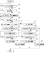
- FIG. 4 is a flowchart showing a flow of a start control process executed by the transmission control unit of the first embodiment.
- FIG. 5 is a torque flow diagram showing a flow of MG1 torque in a multi-stage gear transmission when a shift pattern of “EV2nd” is selected.
- FIG. 5 is a torque flow diagram showing a flow of MG1 torque in a multi-stage gear transmission when a shift pattern of “EV1st” is selected.
- the start control device includes a hybrid vehicle (an example of an electric vehicle) including, as drive system components, one engine, two motor generators, and a multi-stage gear transmission having three engagement clutches. Is applied.
- a hybrid vehicle an example of an electric vehicle
- the configuration of the start control device for a hybrid vehicle in the first embodiment will be described by being divided into “overall system configuration”, “shift control system configuration”, “shift pattern configuration”, and “start control processing configuration”.
- FIG. 1 shows a drive system and a control system of a hybrid vehicle to which the start control device of the first embodiment is applied.
- the overall system configuration will be described below with reference to FIG.
- the drive system of the hybrid vehicle includes an internal combustion engine ICE, a first motor generator MG1, a second motor generator MG2, and a multi-stage gear transmission 1 having three engagement clutches C1, C2, C3.
- ICE is an abbreviation for “Internal-Combustion Engine”.
- the internal combustion engine ICE is, for example, a gasoline engine or a diesel engine disposed in the front room of the vehicle with the crankshaft direction as the vehicle width direction.
- the internal combustion engine ICE is connected to the transmission case 10 of the multi-stage gear transmission 1 and the output shaft of the internal combustion engine is connected to the first shaft 11 of the multi-stage gear transmission 1.
- the internal combustion engine ICE basically starts MG2 using the second motor generator MG2 as a starter motor. However, the starter motor 2 is left in preparation for the case where the MG2 start using the high-power battery 3 cannot be secured, such as at a very low temperature.
- Both the first motor generator MG1 and the second motor generator MG2 are three-phase AC permanent magnet synchronous motors using the high-power battery 3 as a common power source.
- the stator of first motor generator MG1 is fixed to the case of first motor generator MG1, and the case is fixed to transmission case 10 of multi-stage gear transmission 1.
- a first motor shaft that is integral with the rotor of first motor generator MG1 is connected to second shaft 12 of multi-stage gear transmission 1.
- the stator of the second motor generator MG2 is fixed to the case of the second motor generator MG2, and the case is fixed to the transmission case 10 of the multi-stage gear transmission 1.
- a second motor shaft integrated with the rotor of second motor generator MG2 is connected to sixth shaft 16 of multi-stage gear transmission 1.
- a first inverter 4 that converts direct current to three-phase alternating current during power running and converts three-phase alternating current to direct current during regeneration is connected to the stator coil of first motor generator MG1 via first AC harness 5.
- a second inverter 6 is connected to the stator coil of the second motor generator MG2 via a second AC harness 7 for converting direct current into three-phase alternating current during power running and converting three-phase alternating current into direct current during regeneration.
- the high-power battery 3 is connected to the first inverter 4 and the second inverter 6 by a DC harness 8 via a junction box 9.
- the multi-stage gear transmission 1 is a constantly meshing transmission having a plurality of gear pairs with different gear ratios, and is arranged in parallel with each other in a transmission case 10 and has six gear shafts 11 to 16 provided with gears. And three engagement clutches C1, C2, C3 for selecting a gear pair.
- As the gear shaft a first shaft 11, a second shaft 12, a third shaft 13, a fourth shaft 14, a fifth shaft 15, and a sixth shaft 16 are provided.
- As the engagement clutch a first engagement clutch C1, a second engagement clutch C2, and a third engagement clutch C3 are provided.
- the transmission case 10 is provided with an electric oil pump 20 that supplies lubricating oil to a bearing portion and a gear meshing portion in the case.
- the first shaft 11 is a shaft to which the internal combustion engine ICE is connected.
- a first gear 101, a second gear 102, and a third gear 103 are arranged in order from the right side of FIG. .
- the first gear 101 is provided integrally (including integrated fixing) with respect to the first shaft 11.
- the second gear 102 and the third gear 103 are idle gears in which bosses protruding in the axial direction are inserted into the outer periphery of the first shaft 11, and are connected to the first shaft 11 via the second engagement clutch C2. It is provided so that drive connection is possible.
- the second shaft 12 is a cylindrical shaft that is connected to the first motor generator MG1 and is coaxially arranged with the axial center aligned with the outer position of the first shaft 11, and the second shaft 12 has a right side in FIG.
- a fourth gear 104 and a fifth gear 105 are arranged in this order.
- the fourth gear 104 and the fifth gear 105 are provided integrally with the second shaft 12 (including integrated fixing).
- the third shaft 13 is a shaft disposed on the output side of the multi-stage gear transmission 1.
- the third shaft 13 includes a sixth gear 106, a seventh gear 107, and an eighth gear in order from the right side of FIG. 108, a ninth gear 109, and a tenth gear 110 are arranged.
- the sixth gear 106, the seventh gear 107, and the eighth gear 108 are provided integrally with the third shaft 13 (including integrated fixing).
- the ninth gear 109 and the tenth gear 110 are idle gears in which bosses protruding in the axial direction are inserted into the outer periphery of the third shaft 13, and are connected to the third shaft 13 via the third engagement clutch C3. It is provided so that drive connection is possible.
- the sixth gear 106 meshes with the second gear 102 of the first shaft 11, the seventh gear 107 meshes with the sixteenth gear 116 of the differential gear 17, and the eighth gear 108 meshes with the third gear 103 of the first shaft 11.
- the ninth gear 109 meshes with the fourth gear 104 of the second shaft 12, and the tenth gear 110 meshes with the fifth gear 105 of the second shaft 12.
- the fourth shaft 14 is a shaft whose both ends are supported by the transmission case 10, and the eleventh gear 111, the twelfth gear 112, and the thirteenth gear 113 are sequentially arranged on the fourth shaft 14 from the right side in FIG. Be placed.
- the eleventh gear 111 is provided integrally with the fourth shaft 14 (including integrated fixation).
- the twelfth gear 112 and the thirteenth gear 113 are idle gears in which bosses protruding in the axial direction are inserted into the outer periphery of the fourth shaft 14, and are connected to the fourth shaft 14 via the first engagement clutch C1. It is provided so that drive connection is possible.
- the eleventh gear 111 is engaged with the first gear 101 of the first shaft 11, the twelfth gear 112 is engaged with the second gear 102 of the first shaft 11, and the thirteenth gear 113 is engaged with the fourth gear 104 of the second shaft 12.
- the fifth shaft 15 is a shaft whose both ends are supported by the transmission case 10, and a fourteenth gear 114 that meshes with the eleventh gear 111 of the fourth shaft 14 is provided integrally (including integral fixing).
- the sixth shaft 16 is a shaft to which the second motor generator MG2 is coupled, and a fifteenth gear 115 that meshes with the fourteenth gear 114 of the fifth shaft 15 is provided integrally (including integrated fixing).
- the second motor generator MG2 and the internal combustion engine ICE are mechanically connected by a gear train including a 15th gear 115, a 14th gear 114, an 11th gear 111, and a first gear 101 that mesh with each other.
- This gear train is a reduction gear train that decelerates the MG2 rotation speed when the internal combustion engine ICE is started by the second motor generator MG2, and the engine rotation is generated during the MG2 power generation that generates the second motor generator MG2 by driving the internal combustion engine ICE. It becomes a speed increasing gear train that increases the number.
- the first engagement clutch C1 is interposed between the twelfth gear 112 and the thirteenth gear 113 of the fourth shaft 14, and is not fastened by a meshing stroke in a rotationally synchronized state by having no synchronization mechanism. It is a dog clutch.
- the first engagement clutch C1 When the first engagement clutch C1 is in the left engagement position (Left), the fourth shaft 14 and the thirteenth gear 113 are drivingly connected.
- the first engagement clutch C1 is in the neutral position (N), the fourth shaft 14 and the twelfth gear 112 are released, and the fourth shaft 14 and the thirteenth gear 113 are released.
- the first engagement clutch C1 is in the right engagement position (Right), the fourth shaft 14 and the twelfth gear 112 are drivingly connected.
- the second engagement clutch C2 is interposed between the second gear 102 and the third gear 103 of the first shaft 11, and is not fastened by a meshing stroke in a rotationally synchronized state by having no synchronization mechanism. It is a dog clutch.
- the second engagement clutch C2 When the second engagement clutch C2 is in the left engagement position (Left), the first shaft 11 and the third gear 103 are drivingly connected.
- the second engagement clutch C2 When the second engagement clutch C2 is in the neutral position (N), the first shaft 11 and the second gear 102 are released, and the first shaft 11 and the third gear 103 are released.
- the second engagement clutch C2 is in the right engagement position (Right), the first shaft 11 and the second gear 102 are drivingly connected.
- the third engagement clutch C3 is interposed between the ninth gear 109 and the tenth gear 110 of the third shaft 13, and is not fastened by a meshing stroke in a rotationally synchronized state by having no synchronization mechanism. It is a dog clutch.
- the third engagement clutch C3 When the third engagement clutch C3 is in the left side engagement position (Left), the third shaft 13 and the tenth gear 110 are drivingly connected.
- the third engagement clutch C3 is in the neutral position (N), the third shaft 13 and the ninth gear 109 are released, and the third shaft 13 and the tenth gear 110 are released.
- the third engagement clutch C3 is in the right engagement position (Right), the third shaft 13 and the ninth gear 109 are drivingly connected.
- a sixteenth gear 116 meshed with a seventh gear 107 provided integrally (including integral fixing) with the third shaft 13 of the multi-stage gear transmission 1 is left and right via the differential gear 17 and the left and right drive shafts 18. Are connected to the drive wheel 19.
- the hybrid vehicle control system includes a hybrid control module 21, a motor control unit 22, a transmission control unit 23, and an engine control unit 24.
- the hybrid control module 21 (abbreviation: “HCM”) is an integrated control means having a function of appropriately managing the energy consumption of the entire vehicle.
- the hybrid control module 21 is connected to other control units (such as a motor control unit 22, a transmission control unit 23, and an engine control unit 24) via a CAN communication line 25 so that bidirectional information can be exchanged.
- CAN of the CAN communication line 25 is an abbreviation of “Controller Area Network”.
- the motor control unit 22 (abbreviation: “MCU”) performs power running control and regenerative control of the first motor generator MG1 and the second motor generator MG2 in accordance with control commands for the first inverter 4 and the second inverter 6.
- Control modes for the first motor generator MG1 and the second motor generator MG2 include “torque control” and “rotational speed FB control”. “Torque control” performs control for causing the actual motor torque to follow the target motor torque when the target motor torque to be shared with respect to the target driving force is determined.
- “Rotational speed FB control” determines the target motor rotational speed to synchronize the clutch input / output rotational speed when there is a shift request for meshing and engaging any of the engagement clutches C1, C2, and C3 during travel. Control is performed to output FB torque so that the rotation speed converges to the target motor rotation speed.
- the transmission control unit 23 (abbreviation: “TMCU”) outputs a current command to the electric actuators 31, 32, 33 (see FIG. 2) based on predetermined input information, thereby shifting the multi-stage gear transmission 1. Shift control for switching patterns is performed.
- the engagement clutches C1, C2, and C3 are selectively meshed and engaged / released, and a gear pair involved in power transmission is selected from a plurality of pairs of gears.
- the first motor generator MG1 or the first motor is used to ensure mesh engagement by suppressing the differential rotational speed of the clutch input / output.
- 2-Rotation speed FB control rotation synchronization control
- the engine control unit 24 (abbreviation: “ECU”) outputs a control command to the motor control unit 22, the ignition plug, the fuel injection actuator, and the like based on predetermined input information, thereby controlling the start-up of the internal combustion engine ICE and the internal combustion engine. Performs engine ICE stop control and fuel cut control.
- the multi-stage gear transmission 1 is characterized in that efficiency is improved by reducing drag by employing engagement clutches C1, C2, and C3 (dog clutches) by mesh engagement as transmission elements. . If there is a shift request for engaging and engaging any of the engagement clutches C1, C2, and C3, the differential rotational speed of the clutch input / output is set to the first motor generator MG1 (when the engagement clutch C3 is engaged) or the second motor. This is realized by synchronizing the rotation with the generator MG2 (when the engagement clutches C1 and C2 are engaged) and starting the meshing stroke when it is within the synchronization determination rotation speed range.
- the transmission control system includes a first engagement clutch C1, a second engagement clutch C2, and a third engagement clutch C3 as engagement clutches.
- a first electric actuator 31, a second electric actuator 32, and a third electric actuator 33 are provided.
- a first engagement clutch operation mechanism 41, a second engagement clutch operation mechanism 42, and a third engagement clutch operation mechanism 43 are provided as mechanisms for converting the actuator operation into a clutch engagement / release operation.
- a transmission control unit 23 is provided as a control means for the first electric actuator 31, the second electric actuator 32, and the third electric actuator 33.
- the first engagement clutch C1, the second engagement clutch C2, and the third engagement clutch C3 are in a neutral position (N: release position), a left engagement position (Left: left clutch engagement engagement position), and a right engagement position. (Right: right clutch meshing engagement position).
- Each of the engagement clutches C1, C2, and C3 has the same configuration, and includes coupling sleeves 51, 52, and 53, left dog clutch rings 54, 55, and 56, and right dog clutch rings 57, 58, and 59.
- the coupling sleeves 51, 52, and 53 are provided so as to be capable of stroke in the axial direction by spline coupling via hubs (not shown) fixed to the fourth shaft 14, the first shaft 11, and the third shaft 13.
- dog teeth 51a, 51b, 52a, 52b, 53a, 53b with flat top surfaces are provided on both sides. Furthermore, fork grooves 51c, 52c, and 53c are provided at the center portions in the circumferential direction of the coupling sleeves 51, 52, and 53.
- the left dog clutch rings 54, 55, 56 are fixed to the bosses of the respective gears 113, 103, 110, which are the left idle gears of the respective engagement clutches C1, C2, C3, and are flat top surfaces facing the dog teeth 51a, 52a, 53a. Dog teeth 54a, 55a, and 56a.
- the right dog clutch rings 57, 58, 59 are fixed to the bosses of the respective gears 112, 102, 109, which are the right idle gears of the engagement clutches C1, C2, C3, and are flat top surfaces facing the dog teeth 51b, 52b, 53b. Dog teeth 57b, 58b, 59b.
- the first engagement clutch operating mechanism 41, the second engagement clutch operating mechanism 42, and the third engagement clutch operating mechanism 43 are used to rotate the electric actuators 31, 32, 33, and to couple the coupling sleeves 51, 52, 53. This is a mechanism for converting to an axial stroke motion.
- Each of the engagement clutch operating mechanisms 41, 42, 43 has the same configuration, and includes rotation links 61, 62, 63, shift rods 64, 65, 66, and shift forks 67, 68, 69.
- One end of each of the rotation links 61, 62, 63 is provided on the actuator shaft of the electric actuator 31, 32, 33, and the other end is connected to the shift rods 64, 65, 66 so as to be relatively displaceable.
- the shift rods 64, 65, 66 are provided with springs 64 a, 65 a, 66 a at rod division positions, and can be expanded and contracted according to the magnitude and direction of the rod transmission force.
- One end of the shift forks 67, 68, 69 is fixed to the shift rods 64, 65, 66, and the other end is disposed in the fork grooves 51c, 52c, 53c of the coupling sleeves 51, 52, 53.
- the transmission control unit 23 includes a vehicle speed sensor 71, an accelerator opening sensor 72, a transmission output shaft rotational speed sensor 73, an engine rotational speed sensor 74, an MG1 rotational speed sensor 75, an MG2 rotational speed sensor 76, an inhibitor switch 77, and the like.
- the sensor signal and switch signal from are input.
- the transmission output shaft rotation speed sensor 73 is provided at the shaft end of the third shaft 13 and detects the shaft rotation speed of the third shaft 13.
- a position servo control unit (for example, a position servo system based on PID control) that controls engagement and disengagement of engagement clutches C1, C2, and C3 determined by the positions of the coupling sleeves 51, 52, and 53 is provided.
- This position servo control unit inputs sensor signals from the first sleeve position sensor 81, the second sleeve position sensor 82, and the third sleeve position sensor 83. Then, the sensor values of the sleeve position sensors 81, 82, 83 are read, and electric currents are supplied to the electric actuators 31, 32, 33 so that the positions of the coupling sleeves 51, 52, 53 become the fastening position or the releasing position by the meshing stroke. give. In other words, the idle gear is set in the engagement state where the dog teeth welded to the coupling sleeves 51, 52, 53 and the dog teeth welded to the idle gear are engaged with each other, so that the idle gear is in the fourth axis.
- the multi-stage gear transmission 1 of the first embodiment reduces power transmission loss by not having a rotation difference absorbing element such as a fluid coupling, and reduces the ICE gear stage by assisting the internal combustion engine ICE by motors, thereby reducing the size ( EV shift stage: 1-2 speed, ICE shift stage: 1-4 speed).
- a rotation difference absorbing element such as a fluid coupling
- the concept of the shift pattern is that, in the starting region where the vehicle speed VSP is equal to or lower than the predetermined vehicle speed VSP0, the multi-stage gear transmission 1 does not have a rotation difference absorbing element.
- the motor starts.
- the traveling region as shown in FIG. 3, when the demand for driving force is large, the concept of a shift pattern is adopted in which the engine driving force is supported by the “parallel HEV mode” that assists the motor driving force. That is, as the vehicle speed VSP increases, the ICE shift speed shifts from (ICE1st ⁇ ) ICE2nd ⁇ ICE3rd ⁇ ICE4th, and the EV shift speed shifts from EV1st ⁇ EV2nd. Therefore, a shift map for issuing a shift request for switching the shift pattern is created based on the concept of the shift pattern shown in FIG.
- FIG. 4 shows a shift pattern that can be obtained by the multi-stage gear transmission 1 having the engagement clutches C1, C2, and C3.
- “Lock” in FIG. 4 represents an interlock pattern that is not established as a shift pattern
- “EV-” represents a state in which the first motor generator MG1 is not drivingly connected to the drive wheel 19
- “ICE-” "Represents a state in which the internal combustion engine ICE is not drivingly connected to the drive wheels 19.
- each shift pattern will be described.
- the shift pattern of “EV- ICEgen” is selected at the time of MG1 idle power generation by the first motor generator MG1 by the internal combustion engine ICE or double idle power generation by adding MG2 power generation to MG1 power generation while the vehicle is stopped. It is a pattern.
- the “Neutral” shift pattern is a pattern selected during MG2 idle power generation in which the second motor generator MG2 generates power with the internal combustion engine ICE while the vehicle is stopped.
- the shift pattern of “EV1st ICE-” is the “EV mode” pattern in which the internal combustion engine ICE is stopped and the first motor generator MG1 is running, or the second motor generator MG2 is generating electric power by the internal combustion engine ICE.
- the first engagement clutch C1 is switched from “N” to “Left” based on deceleration due to insufficient driving force.
- the vehicle shifts to traveling in “parallel HEV mode (first speed)” with a shift pattern of “EV1st ICE1st” in which driving force is ensured.
- the next shift pattern is set depending on the position of the first engagement clutch C1. If the first engagement clutch C1 is “Left”, “EV1.5 ICE2nd”, and if the first engagement clutch C1 is “N”, “EV- ICE2nd”.
- the third engagement clutch C3 When the second engagement clutch C2 is “Left” and the third engagement clutch C3 is “Right”, if the position of the first engagement clutch C1 is “N”, “EV2nd ICE2nd”. Thus, for example, during traveling in “parallel HEV mode” with a shift pattern of “EV1st ICE2nd” selected, the third engagement clutch C3 passes “N” from “Left” to “Right” according to the upshift request. To "”. In this case, the vehicle shifts to “parallel HEV mode” traveling with a shift pattern of “EV2nd ICE2nd” in which the EV shift speed is the second speed.
- the second engagement clutch C2 has passed “N” from “Right” to “Left” in accordance with the downshift request. Switch.
- the vehicle shifts to “parallel HEV mode” traveling with a shift pattern of “EV2nd ICE2nd” in which the ICE shift speed is the second speed.
- the shift pattern of “EV2nd ICE-” is the “EV mode” pattern in which the internal combustion engine ICE is stopped and the first motor generator MG1 is running, or while the second motor generator MG2 is generating power by the internal combustion engine ICE.
- the second engagement clutch C2 is switched from “Right” to “N” in accordance with the upshift request.
- the engagement clutch C1 is switched from “N” to “Right”.
- the vehicle shifts to “parallel HEV mode” traveling by the shift pattern of “EV2nd ICE3rd” in which the ICE shift speed is the third speed.
- the next shift pattern is set depending on the position of the first engagement clutch C1. If the first engagement clutch C1 is “Left”, “EV2.5 ICE4th”, and if the first engagement clutch C1 is “N”, “EV- ICE4th”.
- FIG. 5 shows a flow of a start control process executed by the transmission control unit 23 (start controller) of the first embodiment.
- start controller the transmission control unit 23
- FIG. 5 shows a flow of a start control process executed by the transmission control unit 23 (start controller) of the first embodiment.
- each step of FIG. 5 showing an example of a start control processing configuration will be described.
- the shift pattern of “EV2nd ICE-” when the first engagement clutch C1 and the second engagement clutch C2 are both “N” and the third engagement clutch C3 is “Right” is hereinafter referred to as “EV2nd”.
- the shift pattern of “EV1st ICE-” when the first engagement clutch C1 and the second engagement clutch C2 are both “N” and the third engagement clutch C3 is “Left” is hereinafter referred to as “EV1st”. .
- step S1 it is determined whether or not the vehicle is traveling with the shift pattern “EV2nd” selected. If YES (running on EV2nd), the process proceeds to step S2. If NO (running other than EV2nd), the determination in step S1 is repeated.
- the shift pattern by “EV2nd” indicates that the sensor signals from the first sleeve position sensor 81 and the second sleeve position sensor 82 are “N”, and the sensor signal from the third sleeve position sensor 83 is “Right”. Judgment by indicating the position of ".”
- step S2 following the determination that the shift pattern of “EV2nd” is selected in step S1, it is determined whether deceleration has started. If YES (deceleration start), the process proceeds to step S3. If NO (no deceleration start), the determination in step S2 is repeated.
- the start of deceleration is determined by a decrease in the vehicle speed, an accelerator release operation, a brake depression operation, or the like.
- step S3 following the determination that deceleration starts in step S2, it is determined whether or not EV2nd ⁇ EV1st downshift start for switching the shift pattern from “EV2nd” to “EV1st”. If YES (EV2nd ⁇ EV1st downshift start), the process proceeds to step S4. If NO (EV2nd ⁇ EV1st downshift start is not started), the determination in step S3 is repeated.
- the start of EV2nd ⁇ EV1st downshift is determined based on the presence or absence of a shift request for switching the shift pattern from “EV2nd” to “EV1st”.
- step S4 following the determination that EV2nd ⁇ EV1st downshift start in step S3, it is determined whether or not the vehicle is in a stopped state. If YES (stop the vehicle), the process proceeds to step S5. If NO (running), the determination in step S4 is repeated.
- the vehicle stop state is determined by the vehicle speed signal from the vehicle speed sensor 71 indicating the vehicle stop state.
- step S5 following the determination in step S4 that the vehicle is in a stopped state, it is determined whether or not the downshift to “EV1st” has been completed. If YES (downshift to EV1st completed), the process proceeds to step S6. If NO (downshift to EV1st is not completed), the process proceeds to step S11.
- the sensor signals from the first sleeve position sensor 81 and the second sleeve position sensor 82 indicate the position of “N”, and the sensor signal from the third sleeve position sensor 83 is Judge by indicating the position of “Left”. When the sensor signal from the third sleeve position sensor 83 has not reached the “Left” position, it is determined that the shift to “EV1st” has not been completed.
- step S6 following the determination in step S5 that the downshift to “EV1st” has been completed, whether or not a selection operation has been performed from “D range” to “P range” or “N range” by a lever operation by the driver. Determine whether. If YES (there is a select operation to P, N), the process proceeds to step S7, and if NO (no select operation to P, N), the process proceeds to step S10.
- the selection operation from the “D range” to the “P range” or the “N range” is determined by a switch signal from the inhibitor switch 77.
- step S7 following the determination that there is a selection operation to P or N in step S6 or the determination that there is no selection operation to the D range in step S8, the shift pattern of the multi-stage gear transmission 1 is “EV1st”. Is maintained, and the process proceeds to step S8.
- maintaining “EV1st” means maintaining both the first engagement clutch C1 and the second engagement clutch C2 in the “N” position and the third engagement clutch C3 in the “Left” position.
- step S8 following the maintenance of “EV1st” in step S7, it is determined whether or not a selection operation is performed from “P range” or “N range” to “D range” by a lever operation by the driver. If YES (with a select operation to D), the process proceeds to step S9. If NO (without a select operation to D), the process returns to step S7.
- the selection operation from the “P range” or “N range” to the “D range” is determined by a switch signal from the inhibitor switch 77.
- step S9 following the determination that there is a select operation to “D range” in step S8, the vehicle starts with “EV1st” maintained in step S7 and proceeds to the end.
- step S11 following the determination that the downshift to “EV1st” is not completed in step S5, the shift pattern is returned to “EV2nd” before the downshift is started, and the process proceeds to step S12. That is, when the sensor signal from the third sleeve position sensor 83 has not reached the “Left” position, the coupling sleeve 53 is returned in the reverse direction from the position at the time of vehicle stop determination to the “Right” position.
- step S12 following the return operation to “EV2nd” in step S11, it is determined whether or not a selection operation from “D range” to “P range” or “N range” has been performed by a lever operation by the driver. If YES (with a select operation to P, N), the process proceeds to step S13, and if NO (no select operation to P, N), the process proceeds to step S16.
- the selection operation from the “D range” to the “P range” or the “N range” is determined by a switch signal from the inhibitor switch 77.
- step S13 following the determination that there is a selection operation to P and N in step S12, or the determination that there is no selection operation to the D range in step S14, the shift pattern of the multi-stage gear transmission 1 is “EV2nd”. Is maintained, and the process proceeds to step S14.
- maintaining “EV2nd” means maintaining both the first engagement clutch C1 and the second engagement clutch C2 in the “N” position and the third engagement clutch C3 in the “Right” position.
- step S14 following the maintenance of “EV2nd” in step S13, it is determined whether or not a selection operation is performed from “P range” or “N range” to “D range” by a lever operation by the driver. If YES (with a select operation to D), the process proceeds to step S15. If NO (without a select operation to D), the process returns to step S13.
- the selection operation from the “P range” or “N range” to the “D range” is determined by a switch signal from the inhibitor switch 77.
- step S15 following the determination that there is a select operation to “D range” in step S14, the vehicle starts with “EV2nd” maintained in step S13 and proceeds to the end.
- start control processing operation “start control processing operation”
- start control operation “start control operation”
- step S1 When a downshift is started in which the vehicle starts decelerating in the EV running state by selecting the shift pattern of “EV2nd” and the shift pattern is switched from “EV2nd” to “EV1st” during the deceleration, step S1 ⁇ The process proceeds from step S2 to step S3 to step S4.
- step S4 When the downshift from “EV2nd” to "EV1st” is started, the downshift from "EV2nd” to "EV1st” is advanced during the deceleration period in which it is determined in step S4 that the vehicle has not been stopped. .
- step S4 it is determined in next step S5 whether or not the shift to “EV1st” has been completed. If it is determined in step S5 that the downshift to “EV1st” has been completed, the process proceeds to steps S6 to S10 for maintaining “EV1st” after the downshift. On the other hand, if it is determined in step S5 that the downshift to “EV1st” has not been completed, the routine proceeds to steps S11 to S16 for maintaining “EV2nd” before the downshift.
- step S6 when the vehicle is stopped for a long time or parked for a long time, a selection operation from “D range” to “P range” or “N range” is performed.
- the process proceeds from step S6 to step S7 to step S8. Then, unless the selection operation to “D range” is determined in step S8, the flow from step S7 to step S8 is repeated.
- step S7 “EV1st” is maintained as the shift pattern of the multi-stage gear transmission 1. Is done.
- step S8 when the selection operation to “D range” as a start request is determined in step S8, the process proceeds from step S8 to step S9 ⁇ end, and in step S9, “EV1st” maintained in step S7 is changed.
- the starting shift pattern is used, and the vehicle starts according to the brake foot release operation and accelerator depression operation.
- step S10 “EV1st” in which the downshift is completed is set as a start shift pattern, and the vehicle restarts according to the brake foot release operation and the accelerator depression operation.
- step S11 the shift pattern is reduced. Return to “EV2nd” before the start of shifting. Then, for example, when the vehicle is stopped for a long time or parked for a long time, and a selection operation from “D range” to “P range” or “N range” is performed, the process proceeds from step S12 to step S13 to step S14. move on. Then, unless the selection operation to “D range” is determined in step S14, the flow from step S13 to step S14 is repeated. In step S13, “EV2nd” is maintained as the shift pattern of the multi-stage gear transmission 1. Is done.
- step S14 when the selection operation to “D range” which is a start request is determined in step S14, the process proceeds from step S14 to step S15 ⁇ end, and in step S15, “EV2nd” maintained in step S13 is set.
- the starting shift pattern is used, and the vehicle starts according to the brake foot release operation and accelerator depression operation.
- step S16 “EV2nd” returned in step S11 is set as a start shift pattern, and the vehicle restarts according to the brake foot release operation and the accelerator depression operation.
- the flow of MG1 torque in the multi-stage gear transmission 1 when the shift pattern “EV2nd” is selected will be described with reference to FIG.
- the first engagement clutch C1 is in the “N” position
- the second engagement clutch C2 is in the “N” position
- the third engagement clutch C3 is in the “Right” position.
- the MG1 torque is derived from the first motor generator MG1 from the second shaft 12 ⁇ the fourth gear 104 ⁇ the ninth gear 109 ⁇ the third shaft 13 ⁇ the seventh gear 107 ⁇ the sixteenth gear 116 ⁇ the differential gear 17 ⁇ the drive shaft 18 ⁇ It flows to the drive wheel 19.
- the flow of MG1 torque in the multi-stage gear transmission 1 when the shift pattern “EV1st” is selected will be described with reference to FIG.
- the first engagement clutch C1 is in the “N” position
- the second engagement clutch C2 is in the “N” position
- the third engagement clutch C3 is in the “Left” position.
- the MG1 torque is derived from the first motor generator MG1 from the second shaft 12 ⁇ the fifth gear 105 ⁇ the tenth gear 110 ⁇ the third shaft 13 ⁇ the seventh gear 107 ⁇ the sixteenth gear 116 ⁇ the differential gear 17 ⁇ the drive shaft 18 ⁇ It flows to the drive wheel 19.
- the downshift that switches the shift pattern from “EV2nd” to “EV1st” is performed by moving the coupling sleeve 53 of the third engagement clutch C3 from the “Right” engagement position to the “Left” position via the “N” position. This is achieved by making a stroke to the fastening position. At this time, both the first engagement clutch C1 and the second engagement clutch C2 remain in the “N” position.
- the third engagement clutch C3 having a clutch portion with two engagement positions of “Right” and “Left” corresponds to a start clutch that is engaged when a start request is made.
- the clutch portion constituted by the coupling sleeve 53 and the right dog clutch ring 59 and having the engagement position of the dog teeth 53b, 59b being “Right” is referred to as “MG1 2nd clutch” (second clutch). Equivalent to a starting clutch).
- the clutch portion constituted by the coupling sleeve 53 and the left dog clutch ring 56 and having the engagement positions of the dog teeth 53a, 56a being “Left” is referred to as “MG1 1st clutch” (for the first start) Equivalent to a clutch).
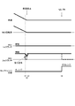
- FIG. 8 shows a time chart when the vehicle is stopped by completing a downshift for switching the shift pattern of the multi-stage gear transmission 1 from “EV2nd” to “EV1st” during deceleration.
- time t1 is the release command time for the MG1 2nd clutch.
- Time t2 is the release completion time of the MG1 2nd clutch.
- Time t3 is the engagement command time of the MG1 1st clutch.
- Time t4 is the engagement completion time of the MG1 1st clutch.
- Time t5 is the vehicle stop time.
- Time t6 is a select operation time from the D range to the P range or the N range.
- FIG. 9 shows a time chart when the vehicle is stopped without completing the downshift for switching the shift pattern of the multi-stage gear transmission 1 from “EV2nd” to “EV1st” during deceleration.
- time t1 is the MG1 2nd clutch release command time.
- Time t2 is the vehicle stop time and the MG1 2nd clutch return engagement command time.
- Time t3 is the time for completing the reverse engagement of the MG1 2nd clutch.
- Time t4 is a select operation time from the D range to the P range or the N range.
- the starting clutch is an engagement clutch
- the stroke cannot be made in the fastening direction.
- the start shock is caused by the fluctuation of the transmission torque in the initial stage.
- it is necessary to fasten after shifting the phase, which takes time. For this reason, if it is going to start by engaging the engagement clutch with the vehicle stopped, it is necessary to wait until the meshing engagement is completed, so that the vehicle cannot start quickly.
- the third engagement clutch C3 since the third engagement clutch C3 is pre-engaged, the engagement operation of the third engagement clutch C3 that is meshed and fastened is not required when a start request is issued from the vehicle stop state. Therefore, the start shock is suppressed and the time required from the start request to the vehicle start is shortened. That is, even when there is a quick start request, a quick start response corresponding to this is ensured.
- the vehicle when passing from the P range to the N range on an uphill road, or when selecting from the P range to the N range, the vehicle slides backward in the N range where the power transmission path is cut off. Similarly, on the down slope road, the vehicle slides forward in the N range.
- the engagement of the third engagement clutch C3 that is engaged when the vehicle is stopped is maintained until the next start including the vehicle stop state. For this reason, even when an operation of passing through the N range or an operation of selecting the N range is performed while the vehicle is stopped on the slope road, the power transmission path is not interrupted and the vehicle is prevented from sliding down.
- the starting shift stage according to “EV1st” or “EV2nd” is maintained until the next D range is selected. (S7, S13). Therefore, even when there is a quick start request from the P range or the N range, the time from the selection operation to the D range to the vehicle start is shortened.
- the downshift control from “EV2nd” to “EV1st” is started during deceleration before the vehicle stops, and the downshift to “EV1st” is completed when the vehicle stops.
- “EV1st” after the downshift is maintained until the next D range is selected (S5 ⁇ S6 ⁇ S7 ⁇ S8). Therefore, when the downshift to “EV1st” is completed when the vehicle is stopped, EV start by “EV1st” having high start drive performance is ensured for the next start request.
- the downshift control from “EV2nd” to “EV1st” is started during deceleration before the vehicle stops, and the downshift to “EV1st” is not completed when the vehicle stops. At this time, it returns to “EV2nd” before the downshift, and when the vehicle is stopped, when the selection operation is performed from the D range to the P range or the N range, the restored “EV2nd” is maintained until the next D range is selected. (S5 ⁇ S11 ⁇ S12 ⁇ S13 ⁇ S14). Accordingly, when the downshift to “EV1st” is not completed when the vehicle is stopped, EV start by “EV2nd” is ensured for the next start request.
- the vehicle re-starts at the start gear stage by “EV1st” or “EV2nd” (S6 ⁇ S10, S12 ⁇ S16). Therefore, for a quick start request that does not perform a select operation for changing the range position, such as when starting from a signal wait, the time from the start request operation to the restart is shortened.
- the transmission is a multi-stage gear transmission 1 of a hybrid vehicle.
- the multi-stage gear transmission 1 includes a third engagement clutch C3 that selects “EV1st” when the stroke direction of the coupling sleeve 53 from the N position is one, and selects “EV2nd” when the other is the other.
- the EV starts with no differential absorption element (Fig. 3). Therefore, when the hybrid vehicle starts EV, the EV start is ensured by selecting the shift pattern “EV1st” or “EV2nd” that uses the coupling sleeve 53 in common.
- An electric motor (first motor generator MG1) as a power source and a transmission (multi-stage gear transmission 1) that shifts the output from the electric motor (first motor generator MG1) and transmits it to the drive wheels 19 in the drive system.
- a transmission multi-stage gear transmission 1
- the electric vehicle having the engagement clutches C1, C2, and C3 that mesh and fasten with a stroke from the release position as a speed change element
- a clutch that meshes and is engaged when a start request is made is called a start clutch (third engagement clutch C3).
- the start controller transmission control unit 23, FIG.
- the transmission (multi-stage gear transmission 1) has a starting gear stage ("EV1st”, “EV2nd”) to which a starting clutch (MG1 1st clutch, MG1 2nd clutch) is engaged,
- the start controller transmission control unit 23, FIG. 5
- the starting shift speed (“EV1st”, “EV2nd”) when the vehicle stops is maintained until “D range” is selected. Therefore, in addition to the effect of (1), even when there is a quick start request from the parking range (P range) or neutral range (N range), the time from the selection operation to the driving range (D range) until the vehicle start Can be shortened.
- the transmission includes a first speed stage (“EV1st”) where the first starting clutch (MG1 1st clutch) is engaged and a second speed stage where the second starting clutch ((MG1 2nd clutch) is engaged ( "EV2nd”) is a multi-stage transmission (multi-stage gear transmission 1),
- the start controller (transmission control unit 23, FIG. 5) starts downshift control from the second gear (“EV2nd") to the first gear (“EV1st”) during deceleration before the vehicle stops.
- the transmission includes a first speed stage (“EV1st”) where the first starting clutch (MG1 1st clutch) is engaged, and a second speed stage where the second starting clutch ((MG1 2nd clutch) is engaged ( "EV2nd”) is a multi-stage transmission (multi-stage gear transmission 1),
- the start controller (transmission control unit 23, FIG. 5) starts downshift control from the second gear (“EV2nd") to the first gear (“EV1st”) during deceleration before the vehicle stops.
- the transmission (multi-stage gear transmission 1) has a start gear stage ("EV1st", “EV2nd") where the start clutch (the MG1 1st clutch and the MG1 2nd clutch of the third engagement clutch C3) is engaged.
- the start controller transmission control unit 23, FIG. 5
- the start gear (“ EV1st ”,“ EV2nd ”) and the vehicle restarts (S6 ⁇ S10, S12 ⁇ S16).
- the time from the start request operation to the restart can be shortened for a quick start request without performing the select operation.
- the electric vehicle is a hybrid vehicle including an electric motor (first motor generator MG1, second motor generator MG2) and an internal combustion engine ICE as power sources,
- the transmission selects the first EV speed (“EV1st”) when the stroke direction of the coupling sleeve 53 from the neutral position (N position) is one, and selects the second EV speed (“EV2nd”) when the other is the other.
- This is a multi-stage gear transmission 1 that has an engagement clutch (third engagement clutch C3) and does not have a rotation-difference absorbing element, and starts an EV.
- Example 2 is an example in which a start control device is applied to an electric vehicle in place of the hybrid vehicle of Example 1.
- the start control device of the second embodiment is applied to an electric vehicle (another example of an electric vehicle) provided with one motor generator and a two-speed gear transmission having one engagement clutch as drive system components. It is a thing.
- an “overall system configuration” of the start control device for an electric vehicle according to the second embodiment will be described.
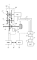
- FIG. 10 shows a drive system and a control system of an electric vehicle to which the start control device of the first embodiment is applied.
- the overall system configuration will be described below with reference to FIG.
- the drive system of the electric vehicle includes a motor generator MG and a second-speed gear transmission 1 'having one engagement clutch C as shown in FIG.
- the motor generator MG is a three-phase AC permanent magnet synchronous motor that uses a high-power battery 3 'as a power source.
- the stator of motor generator MG is fixed to the case of motor generator MG, and the case is fixed to transmission case 10 'of second gear transmission 1'.
- the motor shaft integral with the rotor of the motor generator MG is connected to the first shaft 11 'of the second speed gear transmission 1'.
- An inverter 4 ′ that converts direct current to three-phase alternating current during power running and converts three-phase alternating current to direct current during regeneration is connected to the stator coil of motor generator MG via AC harness 5 ′.
- the high voltage battery 3 'and the inverter 4' are connected by a DC harness 8 'via a junction box 9'.
- the two-speed gear transmission 1 ′ is a constantly meshing transmission having two gear pairs with different gear ratios, and is arranged in parallel with each other in the transmission case 10 ′, and two gear shafts provided with gears; And one engagement clutch C for selecting a gear pair.
- As the gear shaft a first shaft 11 'and a third shaft 13' are provided.
- the first shaft 11 ' is a shaft to which the motor generator MG is connected, and a second gear 102' and a third gear 103 'are arranged on the first shaft 11' in order from the right side of FIG.
- the second gear 102 ′ and the third gear 103 ′ are idle gears in which bosses protruding in the axial direction are inserted into the outer periphery of the first shaft 11 ′, and are connected to the first shaft 11 ′ via the engagement clutch C. On the other hand, it is provided so as to be drive-coupled.
- the third shaft 13 ′ is a shaft disposed on the output side of the second-speed gear transmission 1 ′.
- the third shaft 13 ′ includes a sixth gear 106 ′ and a seventh gear sequentially from the right side of FIG. 107 'and an eighth gear 108' are arranged.
- the sixth gear 106 ', the seventh gear 107', and the eighth gear 108 ' are provided integrally (including integral fixing) with respect to the third shaft 13'.
- the sixth gear 106 ′ meshes with the second gear 102 ′ of the first shaft 11 ′
- the seventh gear 107 ′ meshes with the sixteenth gear 116 ′ of the differential gear 17 ′
- the eighth gear 108 ′ meshes with the first shaft. 11 mesh with the third gear 103 '.
- the engagement clutch C is interposed between the second gear 102 ′ and the third gear 103 ′ of the first shaft 11 ′, and is engaged by a meshing stroke in a rotationally synchronized state by having no synchronization mechanism. It is a dog clutch.
- the engagement clutch C When the engagement clutch C is in the left engagement position (Left), the first shaft 11 'and the third gear 103' are drivingly connected.
- the engagement clutch C When the engagement clutch C is in the neutral position (N), the first shaft 11 'and the second gear 102' are released, and the first shaft 11 'and the third gear 103' are released.
- the engagement clutch C is in the right engagement position (Right), the second gear 102 'of the first shaft 11' is drivingly connected.
- the sixteenth gear 116 'meshed with the seventh gear 107' on the third shaft 13 'of the second speed gear transmission 1' has left and right drive wheels 19 via a differential gear 17 'and left and right drive shafts 18'. 'It is connected to the.
- the electric vehicle control system includes a motor control unit 22 'and a transmission control unit 23'.
- the motor control unit 22 'and the transmission control unit 23' are connected by a CAN communication line 25 'so that bidirectional information can be exchanged.
- the motor control unit 22 ' (abbreviation: "MCU") performs power running control, regenerative control, and the like of the motor generator MG according to a control command for the inverter 4'.
- the transmission control unit 23 ′ (abbreviation: “TMCU”) outputs a current command to an electric actuator (not shown) based on predetermined input information, thereby changing the gear position of the second-speed gear transmission 1 ′.
- TMCU transmission control unit 23 ′
- the engagement clutch C is selectively meshed and engaged / released along the third engagement clutch C3 of the first embodiment, and a gear pair involved in power transmission is selected from the two gear pairs.
- a low gear selection of the gear pair of the third gear 103 'and the eighth gear 108'
- a high gear selection of the gear pair of the second gear 102 'and the sixth gear 106'
- the engagement clutch C has one configuration in the configuration of the first embodiment shown in FIG.
- the “shift pattern configuration” is a configuration in which “low shift speed” and “high shift speed” are switched through the neutral position.
- the “shift control processing configuration” is a configuration in which “EV1st” is read as “low shift speed” and “EV2nd” is read as “high shift speed” in the configuration of the first embodiment shown in FIG. Further, since “shift control processing action” and “shift control action” are also the same as those in the first embodiment, description thereof is omitted.
- An electric vehicle is an electric vehicle having only an electric motor (motor generator MG) as a power source
- the transmission has an engagement clutch C that selects the “low gear” when the stroke direction of the coupling sleeve from the neutral position (N position) is one and the “high gear” when the other is the other. It is a 2nd gear transmission 1 '.
- the structure of the transmission (second gear transmission 1 ′) is simplified, and when starting with an electric vehicle, the “low It is possible to ensure the start by selecting “shift speed” or “high shift speed”.
- an example of a multi-stage gear transmission 1 of a constantly meshing type having three engagement clutches C1, C2, and C3 and having a plurality of gear pairs having different gear ratios is shown as a transmission.
- an example of a two-speed gear transmission 1 ′ having a constant meshing type having one engagement clutch C and two gear pairs having different gear ratios is shown as the transmission.
- the transmission has an engagement clutch that achieves at least one shift stage and meshes and fastens with a stroke from the release position as a shift element, the multi-stage gear shown in the first and second embodiments. It is not limited to the transmission 1 or the second speed gear transmission 1 ′.
- the start control device of the present invention is applied to a hybrid vehicle including, as drive system components, one engine, two motor generators, and a multi-stage gear transmission having three engagement clutches.
- a hybrid vehicle including, as drive system components, one engine, two motor generators, and a multi-stage gear transmission having three engagement clutches.
- an example to do In the second embodiment, an example is shown in which the start control device of the present invention is applied to an electric vehicle including, as drive system components, one motor generator and a two-speed gear transmission having one engagement clutch. It was.
- the start control device of the present invention can be another type of hybrid vehicle or electric vehicle as long as the drive system includes an electric motor as a power source and a transmission having at least one engagement clutch. It can also be applied to electric vehicles such as fuel cell vehicles.
Landscapes
- Engineering & Computer Science (AREA)
- Mechanical Engineering (AREA)
- General Engineering & Computer Science (AREA)
- Chemical & Material Sciences (AREA)
- Combustion & Propulsion (AREA)
- Transportation (AREA)
- Hybrid Electric Vehicles (AREA)
- Electric Propulsion And Braking For Vehicles (AREA)
- Control Of Transmission Device (AREA)
- Control Of Driving Devices And Active Controlling Of Vehicle (AREA)
- Hydraulic Clutches, Magnetic Clutches, Fluid Clutches, And Fluid Joints (AREA)
Abstract
Description
この電動車両において、係合クラッチのうち、発進要求があったときに噛み合い締結されるクラッチを発進用クラッチというとき、車両が停止したときに発進用クラッチが締結されていると、車両停止状態を含めて次に発進するまで発進用クラッチの締結を維持する発進コントローラを設ける。
即ち、発進用クラッチが係合クラッチの場合は、歯の頂面同士の位相が合っていると、締結方向にストロークできず、位相をずらしてから締結させる必要があり時間を要する。
これに対し、発進用クラッチが予め締結されていることで、車両停止状態から発進要求があった場合、噛み合い締結される発進用クラッチの締結動作が不要となり、発進ショックが抑えられると共に、発進要求から車両発進までに要する時間が短縮される。
この結果、発進要求があった場合、発進ショックを抑えながら、発進要求に対し応答の良い車両発進を達成することができる。
実施例1の発進制御装置は、駆動系構成要素として、1つのエンジンと、2つのモータジェネレータと、3つの係合クラッチを有する多段歯車変速機と、を備えたハイブリッド車両(電動車両の一例)に適用したものである。以下、実施例1におけるハイブリッド車両の発進制御装置の構成を、「全体システム構成」、「変速制御系構成」、「変速パターン構成」、「発進制御処理構成」に分けて説明する。
図1は、実施例1の発進制御装置が適用されたハイブリッド車両の駆動系及び制御系を示す。以下、図1に基づき、全体システム構成を説明する。
前記第5軸15は、変速機ケース10に両端が支持された軸であり、第4軸14の第11歯車111と噛み合う第14歯車114が一体(一体化固定を含む)に設けられる。
前記第6軸16は、第2モータジェネレータMG2が連結される軸であり、第5軸15の第14歯車114と噛み合う第15歯車115が一体(一体化固定を含む)に設けられる。
そして、第2モータジェネレータMG2と内燃機関ICEは、互いに噛み合う第15歯車115、第14歯車114、第11歯車111、第1歯車101により構成されるギヤ列により機械的に連結されている。このギヤ列は、第2モータジェネレータMG2による内燃機関ICEのMG2始動時、MG2回転数を減速する減速ギヤ列となり、内燃機関ICEの駆動で第2モータジェネレータMG2を発電するMG2発電時、機関回転数を増速する増速ギヤ列となる。
実施例1の多段歯車変速機1は、変速要素として、噛み合い締結による係合クラッチC1,C2,C3(ドグクラッチ)を採用することにより引き摺りを低減することで効率化を図った点を特徴とする。そして、係合クラッチC1,C2,C3のいずれかを噛み合い締結させる変速要求があると、クラッチ入出力の差回転数を、第1モータジェネレータMG1(係合クラッチC3の締結時)又は第2モータジェネレータMG2(係合クラッチC1,C2の締結時)により回転同期させ、同期判定回転数範囲内になると噛み合いストロークを開始することで実現している。又、締結されている係合クラッチC1,C2,C3のいずれかを解放させる変速要求があると、解放クラッチのクラッチ伝達トルクを低下させ、解放トルク判定値以下になると解放ストロークを開始することで実現している。以下、図2に基づき、多段歯車変速機1の変速制御系構成を説明する。
実施例1の多段歯車変速機1は、流体継手などの回転差吸収要素を持たないことで動力伝達損失を低減すると共に、内燃機関ICEをモータアシストすることでICE変速段を減らし、コンパクト化(EV変速段:1-2速、ICE変速段:1-4速)を図った点を特徴とする。以下、図3及び図4に基づき、多段歯車変速機1の変速パターン構成を説明する。
図5は、実施例1の変速機コントロールユニット23(発進コントローラ)で実行される発進制御処理の流れを示す。以下、発進制御処理構成の一例をあらわす図5の各ステップについて説明する。この処理において、第1係合クラッチC1及び第2係合クラッチC2が共に「N」で、第3係合クラッチC3が「Right」のときの「EV2nd ICE-」の変速パターンを、以下「EV2nd」という。また、第1係合クラッチC1及び第2係合クラッチC2が共に「N」で、第3係合クラッチC3が「Left」のときの「EV1st ICE-」の変速パターンを、以下「EV1st」という。
ここで、「EV2nd」による変速パターンは、第1スリーブ位置センサ81及び第2スリーブ位置センサ82からのセンサ信号が「N」の位置を示し、第3スリーブ位置センサ83からのセンサ信号が「Right」の位置を示すことで判断する。
ここで、減速開始は、車速の低下やアクセル足離し操作やブレーキ踏み込み操作などにより判断する。
ここで、EV2nd→EV1stダウン変速開始は、「EV2nd」から「EV1st」へと変速パターンを切り替える変速要求の有無により判断する。
ここで、車両停止状態は、車速センサ71からの車速信号が車両停止状態を示すことにより判断する。
ここで、「EV1st」へのダウン変速完了は、第1スリーブ位置センサ81及び第2スリーブ位置センサ82からのセンサ信号が「N」の位置を示し、第3スリーブ位置センサ83からのセンサ信号が「Left」の位置を示すことで判断する。そして、第3スリーブ位置センサ83からのセンサ信号が「Left」の位置に到達していない場合は、「EV1st」への変速未完了であると判断する。
ここで、「Dレンジ」から「Pレンジ」又は「Nレンジ」へのセレクト操作は、インヒビタースイッチ77からのスイッチ信号により判断する。
ここで、「EV1st」を維持するとは、第1係合クラッチC1及び第2係合クラッチC2を共に「N」位置とし、第3係合クラッチC3を「Left」位置とする状態を保つことをいう。
ここで、「Pレンジ」又は「Nレンジ」から「Dレンジ」へのセレクト操作は、インヒビタースイッチ77からのスイッチ信号により判断する。
つまり、第3スリーブ位置センサ83からのセンサ信号が「Left」の位置に到達していない場合は、カップリングスリーブ53を車両停止判断時の位置から「Right」の位置まで逆方向に戻す。
ここで、「Dレンジ」から「Pレンジ」又は「Nレンジ」へのセレクト操作は、インヒビタースイッチ77からのスイッチ信号により判断する。
ここで、「EV2nd」を維持するとは、第1係合クラッチC1及び第2係合クラッチC2を共に「N」位置とし、第3係合クラッチC3を「Right」位置とする状態を保つことをいう。
ここで、「Pレンジ」又は「Nレンジ」から「Dレンジ」へのセレクト操作は、インヒビタースイッチ77からのスイッチ信号により判断する。
実施例1のハイブリッド車両の発進制御装置における作用を、「発進制御処理作用」、「発進制御作用」、「発進制御の特徴作用」に分けて説明する。
以下、図5に示すフローチャートに基づき、「EV2nd」の変速パターンによるEV走行状態で減速及び変速を開始して車両停止し、車両停止状態からEV発進するときの発進制御処理作用を説明する。
以下、図6~図9に基づき、「EV2nd」から「EV1st」へと変速パターンを切り替えるダウン変速を伴う発進制御作用を説明する。
「EV2nd」の変速パターンでは、第1係合クラッチC1が「N」位置であり、第2係合クラッチC2が「N」位置であり、第3係合クラッチC3が「Right」位置である。従って、MG1トルクは、第1モータジェネレータMG1から第2軸12→第4歯車104→第9歯車109→第3軸13→第7歯車107→第16歯車116→デファレンシャル歯車17→ドライブ軸18→駆動輪19へと流れる。
「EV1st」の変速パターンでは、第1係合クラッチC1が「N」位置であり、第2係合クラッチC2が「N」位置であり、第3係合クラッチC3が「Left」位置である。従って、MG1トルクは、第1モータジェネレータMG1から第2軸12→第5歯車105→第10歯車110→第3軸13→第7歯車107→第16歯車116→デファレンシャル歯車17→ドライブ軸18→駆動輪19へと流れる。
実施例1では、車両が停止したときに第3係合クラッチC3が締結されていると、車両停止状態を含めて次に発進するまで第3係合クラッチC3の締結を維持する構成とした。
これに対し、第3係合クラッチC3が予め締結されていることで、車両停止状態から発進要求があった場合、噛み合い締結される第3係合クラッチC3の締結動作が不要となる。従って、発進ショックが抑えられると共に、発進要求から車両発進までに要する時間が短縮される。つまり、素早い発進要求があった場合にも、これに対応する素早い発進応答が確保される。
これに対し、車両が停止したときに締結されている第3係合クラッチC3の締結を、車両停止状態を含めて次に発進するまで維持する。このため、勾配路での車両停止状態において、Nレンジを通過する操作やNレンジへセレクトする操作をしても、動力伝達経路が遮断されることなく、車両のずり下がりが防止される。
従って、PレンジやNレンジから素早い発進要求があった場合でも、Dレンジへのセレクト操作から車両発進までの時間が短縮される。
従って、車両停止時に「EV1st」へのダウン変速が完了しているとき、次の発進要求に対して発進駆動性能が高い「EV1st」によるEV発進が確保される。
従って、車両停止時に「EV1st」へのダウン変速が完了していないとき、次の発進要求に対して「EV2nd」によるEV発進が確保される。
従って、信号待ちからの発進時などで、レンジ位置を変更するセレクト操作を行わない素早い発進要求に対し、発進要求操作から再発進までの時間が短縮される。
従って、ハイブリッド車両でEV発進する際、カップリングスリーブ53を共通とする「EV1st」又は「EV2nd」の変速パターンを選択してのEV発進が確保される。
実施例1のハイブリッド車両の発進制御装置にあっては、下記に列挙する効果が得られる。
係合クラッチC1,C2,C3のうち、発進要求があったときに噛み合い締結されるクラッチを発進用クラッチ(第3係合クラッチC3)というとき、車両が停止したときに発進用クラッチ(第3係合クラッチC3)が締結されていると、車両停止状態を含めて次に発進するまで発進用クラッチ(第3係合クラッチC3)の締結を維持する発進コントローラ(変速機コントロールユニット23、図5)を設ける。
このため、発進要求があった場合、発進ショックを抑えながら、発進要求に対し応答の良い車両発進を達成することができる。加えて、勾配路での車両停止状態において、ニュートラルレンジ(Nレンジ)を通過する操作やニュートラルレンジ(Nレンジ)へセレクトする操作をしても、車両のずり下がりを防止することができる。
発進コントローラ(変速機コントロールユニット23、図5)は、車両停止状態で走行レンジ(Dレンジ)からパーキングレンジ(Pレンジ)やニュートラルレンジ(Nレンジ)へセレクト操作されると、次に走行レンジ(Dレンジ)が選択されるまで車両停止したときの発進変速段(「EV1st」、「EV2nd」)を維持する。
このため、(1)の効果に加え、パーキングレンジ(Pレンジ)やニュートラルレンジ(Nレンジ)から素早い発進要求があった場合でも、走行レンジ(Dレンジ)へのセレクト操作から車両発進までの時間を短縮することができる。
発進コントローラ(変速機コントロールユニット23、図5)は、車両停止前の減速中に2速段(「EV2nd」)から1速段(「EV1st」)へのダウン変速制御が開始され、車両停止時に1速段(「EV1st」)へのダウン変速が完了しているとき、車両停止状態で走行レンジ(Dレンジ)からパーキングレンジ(Pレンジ)やニュートラルレンジ(Nレンジ)へセレクト操作されると、次に走行レンジ(Dレンジ)が選択されるまでダウン変速後の1速段(「EV1st」)を維持する(S5→S6→S7→S8)。
このため、(2)の効果に加え、車両停止時に1速段(「EV1st」)へのダウン変速が完了しているとき、次の発進要求に対して発進駆動性能が高い1速段(「EV1st」)によるEV発進を確保することができる。
発進コントローラ(変速機コントロールユニット23、図5)は、車両停止前の減速中に2速段(「EV2nd」)から1速段(「EV1st」)へのダウン変速制御が開始され、車両停止時に1速段(「EV1st」)へのダウン変速が完了していないとき、ダウン変速前の2速段(「EV2nd」)に戻し、車両停止状態で走行レンジ(Dレンジ)からパーキングレンジ(Pレンジ)やニュートラルレンジ(Nレンジ)へセレクト操作されると、次に走行レンジ(Dレンジ)が選択されるまで戻した2速段(「EV2nd」)を維持する(S5→S11→S12→S13→S14)。
このため、(2)の効果に加え、車両停止時に1速段(「EV1st」)へのダウン変速が完了していないとき、次の発進要求に対して2速段(「EV2nd」)によるEV発進を確保することができる。
発進コントローラ(変速機コントロールユニット23、図5)は、車両停止状態で走行レンジ(Dレンジ)のままで他のレンジ(P,Nレンジ)へのセレクト操作を行わないと、発進変速段(「EV1st」、「EV2nd」)で再発進する(S6→S10、S12→S16)。
このため、(1)~(4)の効果に加え、セレクト操作を行わない素早い発進要求に対し、発進要求操作から再発進までの時間を短縮することができる。
変速機は、ニュートラル位置(N位置)からのカップリングスリーブ53のストローク方向が一方のときEV1速段(「EV1st」)を選択し、他方のときEV2速段(「EV2nd」)を選択する係合クラッチ(第3係合クラッチC3)を有し、回転差吸収要素を持たないことによりEV発進する多段歯車変速機1である。
このため、(1)~(5)の効果に加え、ハイブリッド車両でEV発進する際、カップリングスリーブ53を共通とする「EV1st」又は「EV2nd」の変速パターンを選択してのEV発進を確保することができる。
実施例2の発進制御装置は、駆動系構成要素として、1つのモータジェネレータと、1つの係合クラッチを有する2速歯車変速機と、を備えた電気自動車(電動車両の他の一例)に適用したものである。以下、実施例2における電気自動車の発進制御装置の「全体システム構成」を説明する。
図10は、実施例1の発進制御装置が適用された電気自動車の駆動系及び制御系を示す。以下、図10に基づき、全体システム構成を説明する。
(7) 電動車両は、動力源として電動機(モータジェネレータMG)のみを備えた電気自動車であり、
変速機は、ニュートラル位置(N位置)からのカップリングスリーブのストローク方向が一方のときに「ロー変速段」を選択し、他方のときに「ハイ変速段」を選択する係合クラッチCを有する2速歯車変速機1’である。
このため、上記(1)~(5)の効果に加え、変速機(2速歯車変速機1’)の構成を簡潔としながら、電気自動車で発進する際、カップリングスリーブを共通とする「ロー変速段」又は「ハイ変速段」を選択しての発進を確保することができる。
Claims (7)
- 駆動系に、動力源としての電動機と、前記電動機からの出力を変速して駆動輪へ伝達する変速機と、を備え、前記変速機は、変速要素として、解放位置からのストロークにより噛み合い締結する係合クラッチを有する電動車両において、
前記係合クラッチのうち、発進要求があったときに噛み合い締結されるクラッチを発進用クラッチというとき、車両が停止したときに前記発進用クラッチが締結されていると、車両停止状態を含めて次に発進するまで前記発進用クラッチの締結を維持する発進コントローラを設ける
ことを特徴とする電動車両の発進制御装置。 - 請求項1に記載された電動車両の発進制御装置において、
前記変速機は、前記発進用クラッチが締結される発進変速段を有し、
前記発進コントローラは、車両停止状態で走行レンジからパーキングレンジやニュートラルレンジへセレクト操作されると、次に走行レンジがセレクトされるまで前記発進変速段を維持する
ことを特徴とする電動車両の発進制御装置。 - 請求項2に記載された電動車両の発進制御装置において、
前記変速機は、第1発進用クラッチが締結される1速段と、第2発進用クラッチが締結される2速段を有し、
前記発進コントローラは、車両停止前の減速中に前記2速段から前記1速段へのダウン変速制御が開始され、車両停止時に前記1速段へのダウン変速が完了しているとき、車両停止状態で走行レンジからパーキングレンジやニュートラルレンジへセレクト操作されると、次に走行レンジが選択されるまでダウン変速後の前記1速段を維持する
ことを特徴とする電動車両の発進制御装置。 - 請求項2に記載された電動車両の発進制御装置において、
前記変速機は、第1発進用クラッチが締結される1速段と、第2発進用クラッチが締結される2速段を有し、
前記発進コントローラは、車両停止前の減速中に前記2速段から前記1速段へのダウン変速制御が開始され、車両停止時に前記1速段へのダウン変速が完了していないとき、ダウン変速前の前記2速段に戻し、車両停止状態で走行レンジからパーキングレンジやニュートラルレンジへセレクト操作されると、次に走行レンジが選択されるまで戻した前記2速段を維持する
ことを特徴とする電動車両の発進制御装置。 - 請求項1から請求項4までの何れか一項に記載された電動車両の発進制御装置において、
前記変速機は、前記発進用クラッチが締結される発進変速段を有し、
前記発進コントローラは、車両停止状態で走行レンジのままで他のレンジへのセレクト操作を行わないと、前記発進変速段で再発進する
ことを特徴とする電動車両の発進制御装置。 - 請求項1から請求項5までの何れか一項に記載された電動車両の発進制御装置において、
前記電動車両は、動力源として電動機と内燃機関を備えたハイブリッド車両であり、
前記変速機は、ニュートラル位置からのカップリングスリーブのストローク方向が一方のときEV1速段を選択し、他方のときEV2速段を選択する係合クラッチを有し、回転差吸収要素を持たないことによりEV発進する多段歯車変速機である
ことを特徴とする電動車両の発進制御装置。 - 請求項1から請求項5までの何れか一項に記載された電動車両の発進制御装置において、
前記電動車両は、動力源として電動機のみを備えた電気自動車であり、
前記変速機は、ニュートラル位置からのカップリングスリーブのストローク方向が一方のときにロー変速段を選択し、他方のときにハイ変速段を選択する係合クラッチを有する2速歯車変速機である
ことを特徴とする電動車両の発進制御装置。
Priority Applications (11)
| Application Number | Priority Date | Filing Date | Title |
|---|---|---|---|
| KR1020177029788A KR102032041B1 (ko) | 2015-04-14 | 2015-04-14 | 전동 차량의 발진 제어 장치 |
| JP2017512493A JP6493517B2 (ja) | 2015-04-14 | 2015-04-14 | 電動車両の発進制御装置 |
| CA2982744A CA2982744C (en) | 2015-04-14 | 2015-04-14 | Device for controlling starting of electrically driven vehicle |
| BR112017022146-2A BR112017022146B1 (pt) | 2015-04-14 | 2015-04-14 | Dispositivo para controlar a partida de um veículo acionado de maneira elétrica e sistema compreendendo o dispositivo |
| US15/560,563 US10760682B2 (en) | 2015-04-14 | 2015-04-14 | Electrically driven vehicle start control device |
| MYPI2017703843A MY187269A (en) | 2015-04-14 | 2015-04-14 | Device for controlling starting of electric vehicle |
| EP15889152.3A EP3284977B1 (en) | 2015-04-14 | 2015-04-14 | Device for controlling starting of electric vehicle |
| PCT/JP2015/061469 WO2016166814A1 (ja) | 2015-04-14 | 2015-04-14 | 電動車両の発進制御装置 |
| RU2017134574A RU2668329C1 (ru) | 2015-04-14 | 2015-04-14 | Устройство для управления началом движения транспортного средства с электроприводом |
| MX2017012950A MX377104B (es) | 2015-04-14 | 2015-04-14 | DISPOSITiVO PARA CONTROLAR EL ARRANQUE DE UN VEHICULO ELECTRICAMENTE ACCIONADO. |
| CN201580078926.5A CN107532706B (zh) | 2015-04-14 | 2015-04-14 | 电动车辆的起步控制装置 |
Applications Claiming Priority (1)
| Application Number | Priority Date | Filing Date | Title |
|---|---|---|---|
| PCT/JP2015/061469 WO2016166814A1 (ja) | 2015-04-14 | 2015-04-14 | 電動車両の発進制御装置 |
Publications (1)
| Publication Number | Publication Date |
|---|---|
| WO2016166814A1 true WO2016166814A1 (ja) | 2016-10-20 |
Family
ID=57126607
Family Applications (1)
| Application Number | Title | Priority Date | Filing Date |
|---|---|---|---|
| PCT/JP2015/061469 Ceased WO2016166814A1 (ja) | 2015-04-14 | 2015-04-14 | 電動車両の発進制御装置 |
Country Status (11)
| Country | Link |
|---|---|
| US (1) | US10760682B2 (ja) |
| EP (1) | EP3284977B1 (ja) |
| JP (1) | JP6493517B2 (ja) |
| KR (1) | KR102032041B1 (ja) |
| CN (1) | CN107532706B (ja) |
| BR (1) | BR112017022146B1 (ja) |
| CA (1) | CA2982744C (ja) |
| MX (1) | MX377104B (ja) |
| MY (1) | MY187269A (ja) |
| RU (1) | RU2668329C1 (ja) |
| WO (1) | WO2016166814A1 (ja) |
Cited By (1)
| Publication number | Priority date | Publication date | Assignee | Title |
|---|---|---|---|---|
| JP2022512387A (ja) * | 2018-12-14 | 2022-02-03 | ルノー エス.ア.エス. | パーキングブレーキ解除段階における車両の機械的制御のための方法および装置 |
Families Citing this family (30)
| Publication number | Priority date | Publication date | Assignee | Title |
|---|---|---|---|---|
| US10487918B2 (en) | 2016-02-29 | 2019-11-26 | Deere & Company | Integrated starter-generator device with power transmission |
| US10591025B2 (en) | 2016-02-29 | 2020-03-17 | Deere & Company | Integrated starter-generator device with power transmission |
| DE102016113690A1 (de) * | 2016-07-25 | 2018-01-25 | Technische Universität Darmstadt | Verfahren zum Steuern eines Schaltvorganges in einem Antriebssystem sowie Steuerungs-Vorrichtung dafür |
| US10479187B2 (en) * | 2017-11-29 | 2019-11-19 | Deere & Company | Integrated hybrid power system for work vehicle |
| US10519920B2 (en) | 2018-01-17 | 2019-12-31 | Deere & Company | Automatic two-mode high reduction power transmission system |
| CN108583546A (zh) * | 2018-03-30 | 2018-09-28 | 浙江吉利控股集团有限公司 | 一种p挡驻车系统及其控制方法 |
| US10975938B2 (en) | 2019-04-16 | 2021-04-13 | Deere & Company | Multi-mode integrated starter-generator device with electromagnetic actuation assembly |
| US10975937B2 (en) | 2019-04-16 | 2021-04-13 | Deere & Company | Multi-mode integrated starter-generator device with cam arrangement |
| US10920730B2 (en) | 2019-04-16 | 2021-02-16 | Deere & Company | Multi-mode integrated starter-generator device with dog clutch arrangement |
| US10968985B2 (en) | 2019-04-16 | 2021-04-06 | Deere & Company | Bi-directional integrated starter-generator device |
| US11060496B2 (en) | 2019-04-16 | 2021-07-13 | Deere & Company | Multi-mode integrated starter-generator device |
| US10948054B2 (en) | 2019-04-16 | 2021-03-16 | Deere & Company | Multi-mode integrated starter-generator device with solenoid cam actuation apparatus |
| US11156270B2 (en) | 2019-04-16 | 2021-10-26 | Deere & Company | Multi-mode integrated starter-generator device with transmission assembly mounting arrangement |
| US10933731B2 (en) | 2019-04-16 | 2021-03-02 | Deere & Company | Multi-mode integrated starter-generator device with magnetic cam assembly |
| US10920733B2 (en) | 2019-04-16 | 2021-02-16 | Deere & Company | Multi-mode integrated starter-generator device with preloaded clutch |
| US10821820B1 (en) | 2019-04-16 | 2020-11-03 | Deere & Company | Multi-mode starter-generator device transmission with single valve control |
| KR20200142165A (ko) | 2019-06-11 | 2020-12-22 | 현대자동차주식회사 | 차량의 클러치 제어방법 |
| EP3825581B1 (en) * | 2019-11-21 | 2022-09-28 | Ningbo Geely Automobile Research & Development Co., Ltd. | Method for performing rotational speed synchronisation |
| US10900454B1 (en) | 2020-04-03 | 2021-01-26 | Deere & Company | Integrated starter-generator device with unidirectional clutch actuation utilizing a biased lever assembly |
| US11193560B1 (en) | 2020-05-29 | 2021-12-07 | Deere & Company | Work vehicle multi-speed drive assembly with bifurcated clutches |
| US11415199B2 (en) | 2020-05-29 | 2022-08-16 | Deere & Company | Bi-directional multi-speed drive |
| US12043981B2 (en) | 2020-09-25 | 2024-07-23 | Deere & Company | Work vehicle drive with multiple electric machines and torque combining assembly |
| DE102020212811B4 (de) | 2020-10-09 | 2022-10-13 | Vitesco Technologies Germany Gmbh | Kompaktes Steuermodul für ein Fahrzeug mit mindestens einem Elektromotor und einem Getriebe |
| US11326570B1 (en) | 2020-10-26 | 2022-05-10 | Deere & Company | Multi-mode integrated starter-generator device with unidirectional input |
| US11866910B2 (en) | 2021-02-25 | 2024-01-09 | Deere & Company | Work vehicle multi-speed drive assembly with output control clutch |
| US11624170B2 (en) | 2021-02-25 | 2023-04-11 | Deere & Company | Work vehicle multi-speed drive assembly with clutch retention mechanism |
| US11719209B2 (en) | 2021-03-29 | 2023-08-08 | Deere & Company | Integrated starter-generator device with unidirectional clutch actuation utilizing biased lever assembly |
| US11761515B2 (en) | 2021-05-20 | 2023-09-19 | Deere & Company | Work vehicle multi-speed drive assembly with guided dog clutch |
| US11686374B2 (en) | 2021-07-23 | 2023-06-27 | Deere & Company | Work vehicle multi-speed drive assembly providing multiple gear ratios at same step ratio |
| DE102022201800A1 (de) | 2022-02-22 | 2023-06-07 | Zf Friedrichshafen Ag | Hybridgetriebe für zwei elektrische Antriebsmaschinen |
Citations (4)
| Publication number | Priority date | Publication date | Assignee | Title |
|---|---|---|---|---|
| JP2006007968A (ja) * | 2004-06-25 | 2006-01-12 | Nissan Motor Co Ltd | ハイブリット車両駆動伝達装置 |
| JP2008024100A (ja) * | 2006-07-19 | 2008-02-07 | Hitachi Ltd | 自動車の制御装置,制御方法及び変速システム |
| JP2014004942A (ja) * | 2012-06-25 | 2014-01-16 | Honda Motor Co Ltd | ハイブリッド車両の制御装置及び制御方法 |
| WO2014103572A1 (ja) * | 2012-12-26 | 2014-07-03 | 日産自動車株式会社 | 電動車両の変速制御装置 |
Family Cites Families (9)
| Publication number | Priority date | Publication date | Assignee | Title |
|---|---|---|---|---|
| JP3063447B2 (ja) | 1993-02-22 | 2000-07-12 | 日産自動車株式会社 | 電気自動車の発進変速段選択容易化装置 |
| RU2205115C2 (ru) * | 2001-01-03 | 2003-05-27 | Открытое акционерное общество "АВТОВАЗ" | Электромобиль |
| JP2005132143A (ja) * | 2003-10-28 | 2005-05-26 | Nissan Motor Co Ltd | ハイブリッド変速機のエンジン始動制御装置 |
| JP2006234122A (ja) * | 2005-02-28 | 2006-09-07 | Denso Corp | 自動変速機の制御装置 |
| CN1986304A (zh) * | 2006-12-08 | 2007-06-27 | 奇瑞汽车有限公司 | 一种混合动力汽车的控制方法 |
| JP2012002353A (ja) * | 2010-05-19 | 2012-01-05 | Jatco Ltd | 変速機のパーキング機構 |
| CN103189258B (zh) * | 2010-11-04 | 2016-05-11 | 丰田自动车株式会社 | 车辆用混合动力驱动装置 |
| CN202608545U (zh) * | 2012-03-21 | 2012-12-19 | 上海世科嘉车辆技术研发有限公司 | 一种适用于微车两种动力并存的动力装置 |
| KR101371465B1 (ko) | 2012-08-09 | 2014-03-10 | 기아자동차주식회사 | 하이브리드 전기자동차의 출발 제어장치 및 방법 |
-
2015
- 2015-04-14 US US15/560,563 patent/US10760682B2/en active Active
- 2015-04-14 JP JP2017512493A patent/JP6493517B2/ja active Active
- 2015-04-14 EP EP15889152.3A patent/EP3284977B1/en active Active
- 2015-04-14 BR BR112017022146-2A patent/BR112017022146B1/pt not_active IP Right Cessation
- 2015-04-14 CN CN201580078926.5A patent/CN107532706B/zh active Active
- 2015-04-14 MX MX2017012950A patent/MX377104B/es active IP Right Grant
- 2015-04-14 MY MYPI2017703843A patent/MY187269A/en unknown
- 2015-04-14 CA CA2982744A patent/CA2982744C/en active Active
- 2015-04-14 RU RU2017134574A patent/RU2668329C1/ru active
- 2015-04-14 WO PCT/JP2015/061469 patent/WO2016166814A1/ja not_active Ceased
- 2015-04-14 KR KR1020177029788A patent/KR102032041B1/ko not_active Expired - Fee Related
Patent Citations (4)
| Publication number | Priority date | Publication date | Assignee | Title |
|---|---|---|---|---|
| JP2006007968A (ja) * | 2004-06-25 | 2006-01-12 | Nissan Motor Co Ltd | ハイブリット車両駆動伝達装置 |
| JP2008024100A (ja) * | 2006-07-19 | 2008-02-07 | Hitachi Ltd | 自動車の制御装置,制御方法及び変速システム |
| JP2014004942A (ja) * | 2012-06-25 | 2014-01-16 | Honda Motor Co Ltd | ハイブリッド車両の制御装置及び制御方法 |
| WO2014103572A1 (ja) * | 2012-12-26 | 2014-07-03 | 日産自動車株式会社 | 電動車両の変速制御装置 |
Non-Patent Citations (1)
| Title |
|---|
| See also references of EP3284977A4 * |
Cited By (1)
| Publication number | Priority date | Publication date | Assignee | Title |
|---|---|---|---|---|
| JP2022512387A (ja) * | 2018-12-14 | 2022-02-03 | ルノー エス.ア.エス. | パーキングブレーキ解除段階における車両の機械的制御のための方法および装置 |
Also Published As
| Publication number | Publication date |
|---|---|
| MX2017012950A (es) | 2018-02-01 |
| CA2982744C (en) | 2021-04-20 |
| MY187269A (en) | 2021-09-17 |
| US20180106365A1 (en) | 2018-04-19 |
| BR112017022146B1 (pt) | 2023-01-17 |
| EP3284977A4 (en) | 2018-04-25 |
| CN107532706B (zh) | 2019-05-17 |
| BR112017022146A2 (ja) | 2018-07-03 |
| JPWO2016166814A1 (ja) | 2017-12-28 |
| KR102032041B1 (ko) | 2019-10-14 |
| EP3284977B1 (en) | 2019-07-24 |
| EP3284977A1 (en) | 2018-02-21 |
| US10760682B2 (en) | 2020-09-01 |
| JP6493517B2 (ja) | 2019-04-10 |
| RU2668329C1 (ru) | 2018-09-28 |
| CA2982744A1 (en) | 2016-10-20 |
| KR20170128545A (ko) | 2017-11-22 |
| MX377104B (es) | 2025-03-07 |
| CN107532706A (zh) | 2018-01-02 |
Similar Documents
| Publication | Publication Date | Title |
|---|---|---|
| JP6493517B2 (ja) | 電動車両の発進制御装置 | |
| JP6327402B2 (ja) | ハイブリッド車両の駆動力制御装置 | |
| JP6477874B2 (ja) | ハイブリッド車両のモード遷移制御装置 | |
| JP6365774B2 (ja) | ハイブリッド車両のモード遷移制御装置 | |
| JP6384606B2 (ja) | ハイブリッド車両の発電制御装置 | |
| CA2990557C (en) | Transmission control device for a hybrid vehicle | |
| JP6361820B2 (ja) | 車両の変速制御装置 | |
| JP6350749B2 (ja) | 電動車両の発進制御装置 | |
| JP6421698B2 (ja) | ハイブリッド車両の変速制御装置 | |
| JP6372616B2 (ja) | ハイブリッド車両の発進制御装置 | |
| JP6657614B2 (ja) | 電動車両の制動力制御装置 | |
| JP6477272B2 (ja) | 車両の停車時制御装置 | |
| JP6421699B2 (ja) | ハイブリッド車両の回生/変速協調制御装置 |
Legal Events
| Date | Code | Title | Description |
|---|---|---|---|
| 121 | Ep: the epo has been informed by wipo that ep was designated in this application |
Ref document number: 15889152 Country of ref document: EP Kind code of ref document: A1 |
|
| ENP | Entry into the national phase |
Ref document number: 2017512493 Country of ref document: JP Kind code of ref document: A |
|
| WWE | Wipo information: entry into national phase |
Ref document number: 15560563 Country of ref document: US |
|
| WWE | Wipo information: entry into national phase |
Ref document number: 2017134574 Country of ref document: RU |
|
| WWE | Wipo information: entry into national phase |
Ref document number: MX/A/2017/012950 Country of ref document: MX |
|
| ENP | Entry into the national phase |
Ref document number: 2982744 Country of ref document: CA |
|
| ENP | Entry into the national phase |
Ref document number: 20177029788 Country of ref document: KR Kind code of ref document: A |
|
| NENP | Non-entry into the national phase |
Ref country code: DE |
|
| REG | Reference to national code |
Ref country code: BR Ref legal event code: B01A Ref document number: 112017022146 Country of ref document: BR |
|
| ENP | Entry into the national phase |
Ref document number: 112017022146 Country of ref document: BR Kind code of ref document: A2 Effective date: 20171016 |