WO2016166968A1 - 包装袋 - Google Patents
包装袋 Download PDFInfo
- Publication number
- WO2016166968A1 WO2016166968A1 PCT/JP2016/001986 JP2016001986W WO2016166968A1 WO 2016166968 A1 WO2016166968 A1 WO 2016166968A1 JP 2016001986 W JP2016001986 W JP 2016001986W WO 2016166968 A1 WO2016166968 A1 WO 2016166968A1
- Authority
- WO
- WIPO (PCT)
- Prior art keywords
- opening
- line
- guide line
- packaging bag
- opening guide
- Prior art date
- Legal status (The legal status is an assumption and is not a legal conclusion. Google has not performed a legal analysis and makes no representation as to the accuracy of the status listed.)
- Ceased
Links
Images
















Classifications
-
- B—PERFORMING OPERATIONS; TRANSPORTING
- B65—CONVEYING; PACKING; STORING; HANDLING THIN OR FILAMENTARY MATERIAL
- B65D—CONTAINERS FOR STORAGE OR TRANSPORT OF ARTICLES OR MATERIALS, e.g. BAGS, BARRELS, BOTTLES, BOXES, CANS, CARTONS, CRATES, DRUMS, JARS, TANKS, HOPPERS, FORWARDING CONTAINERS; ACCESSORIES, CLOSURES, OR FITTINGS THEREFOR; PACKAGING ELEMENTS; PACKAGES
- B65D33/00—Details of, or accessories for, sacks or bags
-
- B—PERFORMING OPERATIONS; TRANSPORTING
- B65—CONVEYING; PACKING; STORING; HANDLING THIN OR FILAMENTARY MATERIAL
- B65D—CONTAINERS FOR STORAGE OR TRANSPORT OF ARTICLES OR MATERIALS, e.g. BAGS, BARRELS, BOTTLES, BOXES, CANS, CARTONS, CRATES, DRUMS, JARS, TANKS, HOPPERS, FORWARDING CONTAINERS; ACCESSORIES, CLOSURES, OR FITTINGS THEREFOR; PACKAGING ELEMENTS; PACKAGES
- B65D77/00—Packages formed by enclosing articles or materials in preformed containers, e.g. boxes, cartons, sacks or bags
- B65D77/22—Details
- B65D77/30—Opening or contents-removing devices added or incorporated during filling or closing of containers
-
- B—PERFORMING OPERATIONS; TRANSPORTING
- B65—CONVEYING; PACKING; STORING; HANDLING THIN OR FILAMENTARY MATERIAL
- B65D—CONTAINERS FOR STORAGE OR TRANSPORT OF ARTICLES OR MATERIALS, e.g. BAGS, BARRELS, BOTTLES, BOXES, CANS, CARTONS, CRATES, DRUMS, JARS, TANKS, HOPPERS, FORWARDING CONTAINERS; ACCESSORIES, CLOSURES, OR FITTINGS THEREFOR; PACKAGING ELEMENTS; PACKAGES
- B65D31/00—Bags or like containers made of paper and having structural provision for thickness of contents
- B65D31/02—Bags or like containers made of paper and having structural provision for thickness of contents with laminated walls
-
- B—PERFORMING OPERATIONS; TRANSPORTING
- B65—CONVEYING; PACKING; STORING; HANDLING THIN OR FILAMENTARY MATERIAL
- B65D—CONTAINERS FOR STORAGE OR TRANSPORT OF ARTICLES OR MATERIALS, e.g. BAGS, BARRELS, BOTTLES, BOXES, CANS, CARTONS, CRATES, DRUMS, JARS, TANKS, HOPPERS, FORWARDING CONTAINERS; ACCESSORIES, CLOSURES, OR FITTINGS THEREFOR; PACKAGING ELEMENTS; PACKAGES
- B65D75/00—Packages comprising articles or materials partially or wholly enclosed in strips, sheets, blanks, tubes or webs of flexible sheet material, e.g. in folded wrappers
- B65D75/52—Details
- B65D75/58—Opening or contents-removing devices added or incorporated during package manufacture
- B65D75/5805—Opening or contents-removing devices added or incorporated during package manufacture for tearing a side strip parallel and next to the edge, e.g. by means of a line of weakness
Definitions
- the present invention relates to a packaging bag, and more particularly, to a packaging bag that is opened from one side seal part to the other side seal part with fingers.
- packaging bags containing contents such as retort pouches have been widely used. Many of such packaging bags are opened by tearing a portion near the upper seal portion from one side seal portion to the other side seal portion with fingers. For this reason, easy opening portions such as notches and cuts are formed in the side seal portions of many packaging bags. Further, in Patent Document 1 below, in order to facilitate opening, a cutting start flaw processing is performed on the peripheral heat-welded portion, and a continuous cutting flaw processing is performed on the non-heat-sealed portion continuously after the cutting start flaw processing. A flexible packaging bag is disclosed.
- FIG. 27 and FIG. 28 show how the conventional packaging bag is opened.
- the packaging bag of the conventional example is a flat pouch in which the front film 101a and the back film 101b are overlapped, and the left and right side seal portions 102 and 104, the top seal portion 106, and the bottom seal portion 108 are heat sealed.
- the packaging bag is opened from the notch 110 of the left side seal portion 102 to the right side seal portion 104.
- break lines 110 a and 110 b that tear the front film 101 a and the back film 101 b are formed toward the right side seal portion 104.
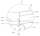
- FIG. 29 shows an enlarged view of a portion surrounded by a broken line C in FIG.
- the arrival point Pa of the breaking line 110a of the front film 101a and the arrival point Pb of the breaking line 110b of the back film 101b are separated by a distance W.
- a large force is required to break the side seal portion 104 while peeling off, it is often difficult to separate the broken piece 100.
- An object of the present invention is to provide a packaging bag in which broken pieces can be easily separated without scattering.
- the inventor according to the present invention when opening the packaging bag, the cutting line of the front film and the cutting line of the back film are the same point on the inner edge of the seal part on the opening end side When it finally reaches, it is not necessary to peel off the front film and the back film with a large force at the seal part on the opening end side, and tearing the seal part on the opening end side with a small shearing force, We paid attention to the fact that it can be easily separated.
- the packaging bag of the present invention has a sealing portion at the end portions of the superposed front film and back film, and is opened from the sealing portion on the opening start side to the sealing portion on the opening end side through the storage portion.
- a front opening guide line provided on the back film, and the front opening guide line and the back opening guide line are linearly drawn in the opening direction extending from the easy opening portion to the seal portion on the opening end side.
- the end portion on the opening end side of the front opening guide line and the end portion on the opening end side of the back opening guide line are inclined with respect to the opened virtual straight line, and the seal portion on the opening end side On or near the inner edge, or opening It is characterized in that overlap each other in the vicinity of the lower edge or on the lower edge of the sealing portion.
- the end portion on the opening end side of the front opening guide line and the end portion on the opening end side of the back opening guide line are on or near the inner edge on the opening end side, or
- the opening guide lines are provided so as to overlap each other on or near the lower edge of the seal portion on the opening opening side. Therefore, when opening the packaging bag, even if the front and back film break lines are shifted up and down, the front film break line and the back film break line reached the front opening guide line and the back film break line, respectively.
- the lines are guided by the front opening guide line and the back opening guide line so that the lines meet and overlap on the inner edge of the seal portion on the opening end side or until reaching the inner edge.
- the break line of the front film guided to the front opening guide line and the break line of the back film guided to the back opening guide line merge, and finally the same point on the inner edge of the seal part at the end of opening To reach.
- the seal portion on the opening end side can be torn with a small shearing force, whereby the broken pieces of the packaging bag can be easily separated.
- the packaging bag of the present invention According to the packaging bag of the present invention, broken pieces can be easily separated when the packaging bag is opened. Furthermore, the contents are prevented from adhering to the hand from the broken pieces and from being scattered during the separation. Moreover, since it is not necessary to use special processing such as laser processing or a special film such as a straight-cutting film, the cost can be reduced.
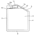
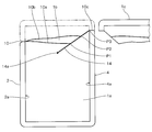
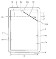
- FIG. 1A shows a front view of a packaging bag according to a first embodiment of the present invention.
- FIG. 1B shows a cross-sectional view along the line BB of FIG. 1A.
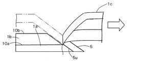
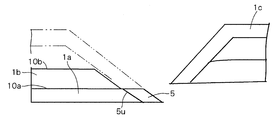
- - 2A to 2C show the unsealed shape of the packaging bag shown in FIG. - 3A to 3D show a broken state in the vicinity of the seal on the end side after opening of the packaging bag according to the first embodiment of the present invention.
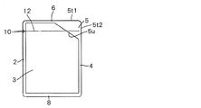
- - 4A to 4F show a modification of the first embodiment.
- - 5A-5F show a further modification of the first embodiment.
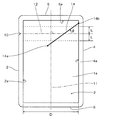
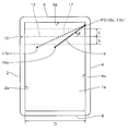
- FIG. 6 shows a plan view of a packaging bag according to a second embodiment of the present invention.
- FIG. 7 shows the top view which shows the structure of the opening guide line in the packaging bag by 2nd Embodiment of this invention.
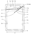
- FIG. 8 shows the top view for demonstrating the induction
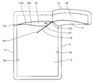
- FIG. 9 shows an opened state of the packaging bag according to the second embodiment of the present invention.
- FIG. 10 shows an unsealed state of the packaging bag according to the second embodiment of the present invention.
- FIG. 11 shows an opened state of the packaging bag according to the second embodiment of the present invention.
- FIG. 12 shows an opened state of the packaging bag according to the second embodiment of the present invention.
- FIG. 13 shows the top view of the modification of the packaging bag by 2nd Embodiment of this invention.
- FIG. 14 shows the top view for demonstrating the induction
- FIG. 15 shows a plan view of a packaging bag according to a third embodiment of the present invention.
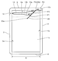
- FIG. 16 shows the top view of the packaging bag by 4th Embodiment of this invention.
- FIG. 17 shows the top view for demonstrating the induction
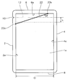
- FIG. 18 shows a plan view of a packaging bag according to a fifth embodiment of the present invention.
- FIG. 15 shows a plan view of a packaging bag according to a third embodiment of the present invention.
- FIG. 16 shows the top view of the packaging bag by 4th Embodiment of this invention.
- FIG. 17 shows the top view for demonstrating the induction
- FIG. 19 shows a plan view of a packaging bag according to a sixth embodiment of the present invention.
- FIG. 20 shows a plan view of a packaging bag according to a seventh embodiment of the present invention.
- FIG. 21 shows a plan view of a packaging bag according to an eighth embodiment of the present invention.
- FIG. 22 is a plan view of a packaging bag according to the ninth embodiment of the present invention.
- FIG. 23 shows a plan view of a packaging bag according to a tenth embodiment of the present invention.
- FIG. 24 is a plan view of a packaging bag according to an eleventh embodiment of the present invention.
- FIG. 26 shows a plan view of a packaging bag according to a twelfth embodiment of the present invention.
- FIG. 27 shows the top view which shows the unsealed state of the packaging bag of a prior art example.
- FIG. 28 shows the top view which shows the unsealed state of the packaging bag of a prior art example.
- FIG. 29 shows an enlarged view of a portion surrounded by a broken line C in FIG.
- FIG. 1A shows a front view of the packaging bag according to the first embodiment of the present invention.
- the packaging bag 1 is a flat pouch in which a front film 1a and a back film 1b are overlapped.
- the packaging bag 1 has a storage portion 3 by a top seal portion 6 at the upper edge, side seal portions 2 and 4 at the left and right edges, and a bottom seal portion 8 at the lower edge (bottom portion) with the opening opening formation side as the upper side. Is formed.
- the contents accommodated in the accommodating part 3 are filled from the bottom part in the packaging bag 1 with which except the bottom part was sealed, for example.
- the packaging bag 1 is sealed by thermally welding the bottom part to form the bottom seal part 8. As shown in FIG. 1B, in the packaging bag 1 filled with the contents, the front film 1a and the back film 1b are swollen back and forth. In addition, it is also possible to fill the packaging bag 1 with the contents from the upper end edge or the left and right side edges of the packaging bag 1.
- the front film 1a and the back film 1b various heat-weldable materials can be adopted.
- the front film 1a and the back film 1b may be, for example, a single-layer film made of a thermoplastic resin that can be heat-welded, or a laminated film having a thermoplastic resin-welded surface.
- Each of the front film 1a and the back film 1b may have a laminated structure in which a barrier layer such as an aluminum layer is sandwiched between laminated films.
- one side seal portion 2 is a seal portion on the opening start end side.
- the side seal part 2 is formed with an easy opening part 10 for opening the upper part of the packaging bag 1.
- the easy-open portion 10 is a notch, but the easy-open portion 10 is not limited to the notch.
- the easy-opening part 10 can employ various configurations such as a single cut or a plurality of cut rows.
- the opening direction of the packaging bag 1 is parallel to the top seal portion 6 and orthogonal to the side seal portion 4.
- An inclined seal portion 5 is formed as a seal portion on the opening end side located in the opening direction as viewed from the easy opening portion 10 on the opening start end side.
- the inclined seal portion 5 is inclined between the top seal portion 6 and the upper end of the other side seal portion 4.
- a straight line extending along the opening direction from the easy-opening portion 10 through the storage portion 3 to the inclined sealing portion 5 on the opening end side is an opening virtual straight line 12.
- the inner edge of the inclined seal portion 5 on the opening end side is the inner edge inclined portion 5u that intersects the opened virtual straight line 12 and forms a predetermined angle ⁇ with respect to the opened virtual straight line 12.
- the inner edge inclined portion 5u of the inclined seal portion 5 covers at least the front-back deviation range S of the break line of the front film 1a and the back film 1b.
- the upper limit Sa and the lower limit Sb of the front / back deviation range S are each schematically shown by a two-dot chain line.
- the front / back deviation range S is located between the upper end 5u1 on the top seal portion 6 side of the inner edge inclined portion 5u of the inclined seal portion 5 and the lower end 5u2 (upper end of the side seal portion 4) on the bottom seal portion 8 (bottom portion) side. Set to do.
- the front / back deviation range S is the distance from the inner edge of the top seal portion 6 of the easy-opening portion 10, the shape and size of the packaging bag 1, the material and thickness of the film, the magnitude of the finger force when breaking the packaging bag 1, and It varies depending on various factors such as direction and breaking speed. For this reason, the front / back deviation range S is statistically set from experimental data for each product, for example. Since the position of the upper limit Sa of the front / back deviation range S is limited by the inner edge of the top seal portion 6, the upper limit Sa of the front / back deviation range S can rise to the upper end 5 u 1 of the inner edge inclined portion 5 u of the inclined seal portion 5.
- the position of the lower limit Sb of the front / back deviation range S needs to be set so that the lower limit Sb does not reach below the lower end 5u2 of the inner edge inclined portion 5u of the inclined seal portion 5 (upper end of the side seal portion 4).
- the front / back deviation range S is determined by the maximum width D in the opening direction of the packaging bag 1. If the height (interval) H from the opening virtual straight line 12 to the lower end 5u2 of the inner edge inclined portion 5u is set to 5/18 or less with respect to the maximum width D in the opening direction of the packaging bag 1, the inner edge inclined portion 5 becomes It was found that the lower limit Sb of the front / back deviation range S can be substantially covered.
- the position of the upper limit Sa of the front / back deviation range S is preferably set so as not to interfere with the top seal portion 6.
- the opening operation of the packaging bag which concerns on this embodiment is demonstrated.
- the easy-opening part 10 of the side seal part 2 which is a seal part on the opening start end side of the packaging bag 1 is broken, and primary opening is performed.
- the broken piece 1c on the top seal portion 6 side is turned to the front side or the back side and pulled as it is in the opening direction toward the inclined seal portion 5 which is the seal portion on the opening end side.
- a shearing force is applied to the packaging bag 1 along the opening virtual straight line 12, and the unsealed front film 1a and back film 1b of the storage unit 3 are broken in a state where they overlap each other, and the secondary opening is performed. (See FIG. 2A). Since the opening virtual straight line 12 is not subjected to a weakening process such as a perforation, the break line between the front film 1a and the back film 1b often deviates from the opening virtual straight line 12.
- the break line 10a of the front film 1a and the break line 10b of the back film 1b proceed while causing a front-back displacement.
- the front ends of the front and back break lines 10a and 10b advance simultaneously.
- the breaking line 10b of the back film 1b shifted upward reaches the inner edge inclined portion 5u of the inclined sealing portion 5 on the opening end side first at the arrival point Pb.
- the breaking line 10b travels along the inner edge inclined portion 5u of the inclined seal portion 5, and merges at the reaching point Pa with the breaking line 10a of the surface film 1a shifted downward, and the broken piece 1c is separated. .
- the upper breaking line reaches the inner edge inclined portion 5u first.
- the inner edge inclined portion is inclined in the direction opposite to the inclination described above, that is, when the upper portion of the inner edge inclined portion is inclined toward the opening end side opposite to the storage portion, the lower breaking line is formed on the inner edge inclined portion. It reaches first, proceeds along the inner edge inclined portion, and merges with the upper breaking line at the arrival point of the upper breaking line.
- 3A shows a state in which the breaking line 10b of the back film 1b located on the upper side has reached the arrival point Pb of the inner edge inclined portion 5u of the inclined seal portion 5.
- FIG. 3B shows a state in which the breaking line 10b of the back film 1b located on the upper side has reached the arrival point Pb of the inner edge inclined portion 5u of the inclined seal portion 5.
- the lower breaking line 10a Simultaneously with the progress of the upper breaking line 10b, the lower breaking line 10a also advances in the tensile direction of the fracture piece 1c, and reaches the upper end Pa at the inner edge inclined portion 5u of the inclined seal portion 5 of the lower breaking line 10a. To the broken line 10b (see FIG. 3C).
- the width of the inclined seal portion 5 is preferably 5 to 15 mm. As the width of the inclined seal portion 5 is larger, it is necessary to increase the tensile force T in the tertiary opening.
- the packaging bag 1 may be broken by an impact such as dropping. As described above, even if the break line is shifted from the primary opening to the secondary opening of the packaging bag 1, the break line joins one arrival point in the tertiary opening. For this reason, the packaging bag 1 can be smoothly broken without requiring an excessive force.
- the virtual opening width W that is the distance between the side seal part 2 on the opening start end side and the inner edge of the inclined seal part 5 on the opening end side along the opening virtual straight line 12 and the inner edge of the inclined seal part 5
- the angle ⁇ formed between the inclined portion 5u and the unsealed virtual straight line 12 will be described.
- the virtual opening width W is preferably about 35 mm or more.
- the virtual opening width W is less than 35 mm, the break line is less likely to be displaced.
- the virtual opening width W is 35 mm or more, the front and back of the fracture line is likely to occur, and the effect of the inner edge inclined portion of the present invention can be sufficiently exhibited.
- the angle ⁇ formed between the inner edge inclined portion 5u of the inclined seal portion 5 and the unsealed virtual straight line 12 is determined by the inner edge inclined portion 5u passing through the reaching point Pa where the breaking line 10b first arrives and the reaching point Pa where it meets, and the unsealed virtual straight line. 12 is an acute angle (FIG. 3). Further, the inner edge inclined portion 5u is inclined to the opening end side opposite to the storage portion, and the lower (bottom side) breaking line first reaches the inner edge inclined portion 5u at the time of opening, and the breaking line starts from the lower reaching point. Is joined to the upper reaching line, the acute angle formed by the inner edge inclined portion 5u from the lower side to the upper side and the opening virtual straight line 12 is the angle ⁇ . (See FIG. 4E).
- the angle ⁇ is preferably 60 ° or less, and more preferably 45 ° or less, so that the magnitude of the component force becomes a certain value or more.
- the angle ⁇ is preferably 20 ° or more.
- the inner edge inclined portion of the seal portion at the opening end side is a straight line inclined at a predetermined angle with respect to the opening direction or at least in the range of deviation of the front and back break lines of the front film and the back film, or the opening direction
- a curve having a tangent line inclined at a predetermined angle various modifications are possible as shown below.
- FIGS. 5A to 5F show modifications of the above-described embodiment. In the following description, only parts different from the packaging bag of the above-described embodiment will be described, and the same components will be denoted by the same reference numerals, and the description thereof will be omitted.
- the outer edge 5t and the inner edge inclined part 5u are not parallel, the inner edge inclined part 5u, the outer edge extension line 5t1 of the top seal part 6, and the outer edge extension line of the side seal part 4 It has a right triangle shape formed with 5t2.
- the inclined seal portion 5 has a wide width, but the third opening of the inclined seal portion 5 is smoothly performed by the break line that merges along the inner edge inclined portion 5u.
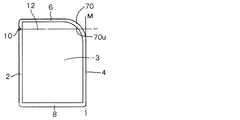
- the inner edge inclined portion 70u of the inclined seal portion 70 shown in FIG. 4B has a curved shape that is curved so as to protrude toward the outside of the storage portion 3, not a linear shape.
- the tangent line of the inner edge inclined portion 70u is inclined at a predetermined angle with respect to the opened virtual straight line 12.
- the packaging bag can be more smoothly broken after reaching the inner edge inclined portion 70u of the inclined seal portion 70 where the upper breaking line is curved until reaching the lower breaking line.
- the inner edge inclined portion 71u of the inclined seal portion 71 shown in FIG. 4C has a polygonal line shape in which a plurality of linear portions having different inclination angles are connected instead of a single inclined straight line.
- the inner edge inclined portion 72u of the inclined seal portion 72 shown in FIG. 4D has a curved shape that is curved so as to protrude toward the inside of the storage portion 3.
- the tangent line of the inner edge inclined portion 72u is inclined at a predetermined angle with respect to the opened virtual straight line 12.
- the inclined seal portion 73 shown in FIG. 4E is a mountain-shaped seal portion 73 having a triangular shape protruding toward the storage portion 3 side.
- the chevron seal portion 73 has a linear first inner edge inclined portion 73a above the top portion 73t and a linear second inner edge inclined portion 73b below the top portion 73t.
- the 1st inner edge inclination part 73a inclines in the opposite direction to the accommodating part 3 as it progresses upwards from the top part 73t.
- the 2nd inner edge inclination part 73b inclines in the opposite direction to the accommodating part 3 as it goes below from the top part 73t.
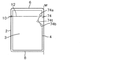
- the inclined seal portion 74 shown in FIG. 4F is a curved seal portion 74 having a semicircular shape that is curved so as to protrude toward the storage portion side.
- the curved seal portion 74 includes a curved first inner edge inclined portion 74a above the top portion 74t, and a curved second inner edge inclined portion 74b below the top portion 74t.
- the tangent lines of the first and second inner edge inclined portions 74 a and 74 b are inclined at a predetermined angle with respect to the opening virtual straight line 12. Also in this modification, it is necessary to set the front / back shift range to one of the first inner edge inclined portion 74a and the second inner edge inclined portion 74b depending on the position of the easy opening portion 10 on the opening start end side. .
- the inner edge inclined portion has a shape protruding toward the storage portion 3 side.
- the inner edge inclined portion is It has a shape projecting outward on the opposite side of the storage part 3.
- the inclined seal portion 5 of the embodiment shown in FIG. 2 is provided in the overhang portion 51 that protrudes on the opposite side to the storage portion 3.
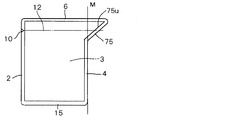
- the packaging bag shown in FIG. 5B has a reverse inclined seal portion 75 obtained by inverting the inclined seal portion 5 of the embodiment shown in FIG. 1 symmetrically with respect to an extension line M extending the outer edge of the side seal portion 4. .
- the inclination direction of the reverse inclination seal part 75 and the inclination direction of the inclination seal part 5 is opposite.
- the lower breaking line reaches the inner edge inclined portion 75u of the reversely inclined seal portion 75 first, and proceeds toward the reaching point of the upper breaking line.
- the packaging bag shown in FIG. 5C has a reverse inclined seal portion 76 obtained by inverting the curved inclined seal portion 70 shown in FIG.
- the reverse inclined seal portion 76 has a curved inner edge inclined portion 76u.
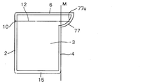
- the packaging bag shown in FIG. 5D has a reverse inclined seal portion 77 obtained by inverting the curved inclined seal portion 71 shown in FIG.
- the reverse inclined seal part 77 has a curved inner edge inclined part 77u.
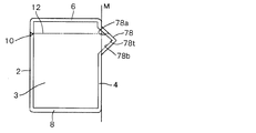
- the packaging bag shown in FIG. 5E has an inverted chevron seal portion 78 obtained by inverting the chevron seal portion 73 shown in FIG.
- the inverted chevron seal portion 78 includes a linear first inner edge inclined portion 78a above the top portion 78t and a linear second inner edge inclined portion 78b below the top portion 78t.
- the first inner edge inclined portion 78a is inclined toward the storage portion as it proceeds upward from the top portion 78t.
- the second inner edge inclined portion 78b is inclined toward the storage portion as it proceeds downward from the top portion 78t.
- the packaging bag shown in FIG. 5F has a reverse curved seal portion 79 obtained by inverting the curved seal portion 74 shown in FIG.
- the curved seal portion 79 has a first inner edge inclined portion 79a above the top portion 79t and a second inner edge inclined portion 79b below the top portion 79t.
- FIG. 6 the top view of the packaging bag of 2nd Embodiment is shown.
- the packaging bag of the present embodiment has a pair of side seal portions 2 and 4 and an opening opening scheduled side (opening opening side) on four sides of the superposed front film 1a and back film 1b (see FIGS. 9 to 12).
- As the upper side a flat pouch heat-sealed by a top seal portion 6 at the upper end edge and a bottom seal portion 8 at the lower end edge (bottom portion), and a surface film 1a in a region surrounded by these seal portions 2, 4, 6, 8 The contents are hermetically sealed between the film and the back film 1b.
- the front film 1a and the back film 1b are constituted by, for example, laminated films in which a nylon layer is laminated on a polyolefin layer.
- various materials and structures that can be thermally welded can be employed for the front film 1a and the back film 1b.
- the front film 1a and the back film 1b may be constituted by a single layer film made of a heat-sealable thermoplastic resin, or may be constituted by a laminated film having a welding surface as a heat-sealable resin.
- the laminated film may have a laminated structure in which a barrier layer is provided in the intermediate layer, or a laminated structure in which a barrier layer is provided in the surface layer.
- the laminated film may have a resin layer as a base material or paper as a base material.
- the front opening guide wire 14 provided on the front film 1a and the back film 1b are provided in the storage part 3, which is an unsealed region between the pair of side seal parts 2 and 4 of the front film 1a and the back film 1b.
- a back opening guide wire 14 is provided in FIG. 6, the front opening guide line and the back opening guide line 14 are overlapped and shown as one line.
- the front opening guide line and the back opening guide line 14 obliquely intersect with the opening virtual straight line 12 and extend along the direction from the lower left to the upper right.
- the unsealing virtual straight line 12 is formed from the easy opening portion 10 of the notch formed in the side seal portion (hereinafter also referred to as “left side seal portion”) 2 on the opening start end side to the side seal portion 4 (hereinafter referred to as “right side”).
- the portion 1c above the easy-open portion 10 (hereinafter also referred to as “fragment”) is an imaginary line along the opening direction in which the finger is pulled.
- the opening virtual straight line 12 is perpendicular to the symmetry axis 11 extending in parallel with the pair of side seal portions 2, 4 at the center between the pair of side seal portions 2, 4, and the opening virtual straight line 12 is the top
- the seal portion 6 extends in parallel with the linear lower edge 6a.
- the angle ⁇ between each of the front opening guide line and the back opening guide line 14 and the opening virtual straight line 12 is preferably 10 to 50 °, and more preferably 20 to 45 °.
- the angle ⁇ is larger than 50 °, the component force in the direction along the opening guide line 14 out of the force pulling along the opening virtual straight line 12 becomes small at the time of opening, and it becomes difficult to tear along the opening guide line 14.
- the angle ⁇ is smaller than 10 °, there is a high possibility that the breaking line does not reach the opening guide line 14 at the time of opening.
- Ends 14b near the right side seal part 4 (hereinafter also referred to as “ends”) of the front opening guide line and the back opening guide line 14 are mutually on the inner edge 4a of the right side seal part 4. overlapping. Thereby, at the time of opening, the breaking line 10a of the front film 1a and the breaking line 10b of the back film 1b are directly guided to one point on the inner edge 4a of the right side seal portion 4 by the front opening guide line and the back opening guide line 14.
- the end 14b can be formed on the inner edge 4a of the right side seal portion 4 if the break line 10a of the front film 1a and the break line 10b of the back film 1b can be substantially guided to one point on the inner edge 4a of the right side seal portion 4. It may not be located and may be located in the vicinity of inner edge 4a. Here, the end 14b in the vicinity of the inner edge 4a is preferably located within 10 mm from the inner edge 4a. The same applies to other embodiments described later.
- each of the front opening guide line and the back opening guide line 14, the end (hereinafter also referred to as “starting end”) 14 a near the left side seal portion 2 (hereinafter also referred to as “starting end”) is located below the opening virtual straight line 12. It is located a predetermined distance L or more away.
- an end (termination) 14 b of the opening guide line 14 near the right side seal portion 4 is located above the opening virtual straight line 12 by a predetermined distance L or more.
- the predetermined distance L is preferably a distance of 28% or more of the length D along the opened virtual straight line 12 between the inner edges 2a and 4a of the pair of side seal portions 2 and 4, more preferably 38% or more. (The same applies to other embodiments described later).
- the ratio of the distance to the length D is experimentally determined so as to include a range in which a break line is formed when the packaging bag is opened.
- FIG. 7 shows an example of the front opening guide line and the back opening guide line 14 of the present embodiment.
- the front opening guide line and the back opening guide line 14 shown in FIG. 7 are configured by the edge 15a of the reinforced portion 15 that is less likely to break than the front film 1a and the back film 1b.
- the reinforcing portion 15 may be formed by partially fusing or bonding the front film 1a and the back film 1b, or between the outer surface side, the inner surface side, or the interlayer of the front film 1a and the back film 1b. You may provide and form a tape.
- the edges of the fused or bonded portions of the front film 1a and the back film 1b are the front opening guide line and the back opening guide line 14 respectively. It becomes.
- the breaking line that has reached the edge 15a of the reinforced portion 15 at the time of opening proceeds along the edge 15a of the reinforced portion 15 because the reinforced portion 15 is not easily broken. For this reason, the edge 15a of the reinforcement
- the front opening guide line and the back opening guide line 14 may be constituted by weakened portions that are more easily broken than the front film 1a and the back film 1b. Since the break line that has reached the weakened portion at the time of opening proceeds along the weakened portion that breaks more easily than the surroundings, the weakened portion functions as the front opening guide line and the back opening guide line 14.
- the weakened portion can be formed as a non-penetrating half cut processed portion in each of the front film 1a and the back film 1b.
- the half-cut processing part is formed by various methods such as laser processing, roll processing with a fine blade attached to the surface, knife processing using a punching die, and polishing processing pressing with a roll with high hardness abrasive grains attached. An appropriate method may be selected from these methods to form a straight or perforated non-penetrating half-cut portion.
- the front opening guide line 14 that guides the breaking line 10a of the front film 1a and the back opening guide line 14 that guides the breaking line 10b of the back film 1b are common as a fusion part.
- the front opening guide wire 14 formed on the front film 1a and the back opening guide wire 14 formed on the back film 1b are formed at positions where they overlap each other. explain. The same applies to the following embodiments.
- FIG. 8 the positions of the break line 10a (hereinafter also referred to as “front break line”) of the front film 1a and the break line 10b (hereinafter also referred to as “back break line”) of the back film 1b at the time of opening are unopened. Shown superimposed on the packaging bag in the state.
- the front break line 10 a of the front film 1 a reaches the point P ⁇ b> 1 on the front opening guide line 14.
- the front break line 10a that has reached the point P1 proceeds along the front opening guide line 14 in the direction indicated by the arrow A1 in FIG.
- the back breaking line 10 b reaches the point P ⁇ b> 2 on the back opening guide line 14, and merges with the front breaking line 10 a that has traveled along the front opening guide line 14.
- the front break line 10a and the reverse break line 10b joined at the point P2 proceed in the direction indicated by the arrow A2 in FIG. 8 along the front opening guide line and the reverse opening guide line 14.
- both the front break line 10a and the back break line 10b reach the terminal ends 14b of the front opening guide line and the back opening guide line 14, respectively. These terminal ends 14b are arranged so as to overlap each other at a point P3 on the inner edge 4a of the right side seal portion 4. For this reason, the front break line 10a and the back break line 10b are directly guided to the point P3 which is the same point on the inner edge 4a of the right side seal portion 4 by the front opening guide line and the back opening guide line 14.
- the front breaking line 10a reaching the opening guide line 14 from the left side and The back breaking line 10 b is guided to the upper side from the arrival point along the front opening guide line and the back opening guide line 14.
- the front break line 10a and the back break line 10b do not advance below the front opening guide line and the back opening guide line 14, but break from the upper surface to the lower side of the contents at the time of opening and the contents are spilled. Can be prevented.
- the back opening guide line 14 which guides the back break line 10b showed the example arrange
- the front opening guide line and the back opening guide line 14 may be arranged separately.
- FIG. 13 shows a modification of the second embodiment.
- the front opening guide line and the back opening guide line are the front opening guide line 16 for guiding the breaking line (front breaking line) 10a of the front film 1a and the breaking line (back breaking line) 10b of the back film 1b.
- the back opening guide line 17 which induces is formed in the front film 1a and the back film 1b as an edge of the weakened part or the reinforced part, respectively.
- the end (starting end) 16a near the left side seal portion 2 of the front opening guide line 16 and the end (starting end) 17a near the left side seal portion 2 of the back opening guide line 17 are arranged at different positions.
- the end (termination) 16b near the right side seal portion 4 of the front opening guide wire 16 and the end (termination) 17b near the right side seal portion 4 of the back opening guide wire 17 are It overlaps at the point P3 on the inner edge 4a.
- FIG. 14 the position of the front break line 10a and the back break line 10b at the time of opening is shown superimposed on the unopened packaging bag.
- the front break line 10a and the back break line 10b extend from the left side seal part 2 toward the right side seal part 4.
- the front break line 10a reaches the point P1 on the front opening guide line 16, and proceeds along the front opening guide line 16 in the direction of the arrow A1 in FIG.
- the back breaking line 10b reaches the point P2 on the back opening guide line 17, and proceeds along the back opening guide line 17 in the direction of the arrow A2 in FIG.
- the end 16b of the front opening guide line 16 and the end 17b of the back opening guide line 17 are arranged at the same point P3 on the inner edge 4a of the right side seal portion 4. For this reason, the front break line 10a and the back break line 10b merge at the point P3. As a result, the right side seal portion 4 can be torn with a small shearing force, and one broken line 10c can travel through the right side seal portion 4 from the point P3, and the broken pieces can be easily separated.
- the packaging bag of 3rd Embodiment is demonstrated with reference to FIG.
- the packaging bag of each following embodiment is substantially the same as that of 2nd Embodiment except an opening guide wire, it attaches
- the unsealing guide line may be formed as a weakened part or an edge of a reinforced part, You may arrange
- the preferred range of the angle formed by the opening guide line with the opening virtual straight line 12 is the same as in the second embodiment.
- an end portion of the opening guide line near the left side seal portion 2 is referred to as a start end, and an end portion near the right side seal portion 4 is referred to as a termination end.
- the front opening guide line and the back opening guide line 18 in the packaging bag of the present embodiment obliquely intersect the opening virtual straight line 12 and extend along the direction from the lower left to the upper right.
- Each end 18b of the front opening guide line and the back opening guide line 18 is separated by a predetermined distance L or more above the opening virtual straight line 12 on the inner edge 4a of the right side seal portion 4 as in the second embodiment. Overlap each other in position. Thereby, the probability that a break line will reach the front opening guide line and the back opening guide line 14 at the time of opening can be increased.
- each of the front opening guide line and the back opening guide line 18 is disposed on the inner edge 2a of the left side seal portion 2.
- the front break line and the reverse break line reach the front opening guide line and the reverse opening guide line 18 respectively, and merge to reach the end 18b on the inner edge 4a of the right side seal portion 4.
- the right side seal part 4 can be torn with a small shearing force, and one broken line can travel through the right side seal part 4 from the terminal end 18b, and the broken pieces can be easily separated. it can.
- the front opening guide line and the back opening guide line 20 in the packaging bag of the present embodiment obliquely intersect with the opening virtual straight line 12 and extend along the direction from the lower left to the upper right.
- the start ends 20a of the front opening guide line and the back opening guide line 20 are located at a predetermined distance L or more below the opening virtual straight line 12 as in the second embodiment. Thereby, the probability that the break line reaches the opening guide line 20 at the time of opening can be increased.
- the terminal ends 20b of the front opening guide line and the back opening guide line 20 are positioned on the lower edge 6a of the top seal portion 6 so as to overlap each other.
- the breaking line proceeding upward from the opening virtual straight line 12 reliably reaches the opening guide line 20 at the time of opening.
- FIG. 17 opening of the packaging bag of this embodiment is demonstrated.
- the position of the front break line 10a and the back break line 10b at the time of opening is shown superimposed on the unopened packaging bag.
- the front break line 10a and the back break line 10b extend from the left side seal part 2 toward the right side seal part 4.
- the front break line 10a reaches the point P1 on the front opening guide line 20, and proceeds in the direction of the arrow A1 along the front opening guide line 20.
- the back breaking line 10 b reaches the point P 2 on the back opening guide line 20 and joins the front breaking line 10 a that has traveled along the front opening guide line 20.
- the front break line 10a and the reverse break line 10b that merge at the point P2 proceed in the direction of the arrow A2 along the front opening guide line and the reverse opening guide line 20.
- both the front breaking line 10a and the rear breaking line 10b are connected to the end opening 20b of the front opening guide line and the back opening guide line 20 by the front opening guide line and the back opening guide line 20, that is, the lower edge of the top seal portion 6. Guided to point P3 on 6a.
- the front break line 10a and the back break line 10b that have reached the point P3 all travel along the lower edge 6a of the top seal part 6 in the direction of the arrow A3, and the lower edge 6a and the right side seal part of the top seal part 6 4 reaches the point P4 of the corner where the inner edge 4a of the four ends.
- the front break guide line 20 and the back break guide line 20 lead the front break line 10a and the back break line 10b to the same point on the inner edge 4a of the right side seal portion 4.
- the right side seal part 4 can be torn with a small shearing force, and one breaking line 10c advances from the point P4 to the right side seal part 4 to easily separate the broken piece. Can do.
- the end 20b can be guided to the same point on the inner edge 4a of the right side seal portion 4 if the front break line 10a and the back break line 10b are aligned and proceed along the lower edge 6a of the top seal portion 6. It does not need to be located on the lower edge 6a of the top seal portion 6, and may be located in the vicinity of the lower edge 6a of the top seal portion 6.
- the end 20b is preferably located within 10 mm from the lower edge 6a in the vicinity of the lower edge 6a. The same applies to other embodiments.
- the front opening guide line and the back opening guide line 22 in the packaging bag of the present embodiment obliquely intersect with the opening virtual straight line 12 and extend along the direction from the lower left to the upper right.
- Each end 22b of the front opening guide line and the back opening guide line 22 is located on the lower edge 6a of the top seal portion 6 as in the fourth embodiment.
- each of the front opening guide line and the back opening guide line 22 is located on the inner edge 2a of the left side seal portion 2.
- the front break line and the reverse break line reach the front opening guide line and the reverse opening guide line 22, respectively, and merge to reach the end 22b that overlaps the lower edge 6a of the top seal portion 6.
- the front break line and the back break line that have reached the terminal end 22b travel together along the lower edge 6a of the top seal portion 6, and the corner where the lower edge 6a of the top seal portion 6 and the inner edge 4a of the right side seal portion 4 meet.
- the right side seal portion 4 can be torn with a small shearing force, and one broken line advances from the corner through the right side seal portion 4 so that the broken pieces can be easily separated. .
- the packaging bag of 6th Embodiment is demonstrated with reference to FIG.
- the front opening guide line and the back opening guide line 30 in the packaging bag of the present embodiment obliquely intersect the opening virtual straight line 12 and extend along the direction from the upper left to the lower right. Yes.
- the end 30b of each of the front opening guide line and the back opening guide line 30 overlaps with each other at a position on the inner edge 4a of the right side seal portion 4 that is lower than the opening virtual straight line 12 by a predetermined distance L or more.
- the front opening guide line and the end 30b of the back opening guide line 30 are preferably arranged at a position higher than the upper surface of the contents so that the contents of the packaging bag do not overflow when opened.
- the upper surface of the contents is below the unsealed virtual straight line 12, In many cases, it is located below the opening virtual straight line 12 by a distance within 23% of the length D along the opening virtual straight line 12 between the inner edges 2a, 4a of the seal portions 2, 4.
- the front opening guide line and the back opening guide line it is preferable that the end 30b of each of the 30 near the right side seal portion 4 is located below the unsealed virtual straight line 12 and at a distance within 23% of the length D from the unsealed virtual straight line 12.
- the starting end 30a of the opening guide line 30 is located above the opening virtual straight line 12 by a predetermined distance L or more. Thereby, at the time of opening, it is possible to increase the probability that the breaking line that advances upward from the opening virtual straight line 12 reaches the opening guide line 30.
- the front break line and the reverse break line reach the front opening guide line and the reverse opening guide line 30, respectively, and merge to reach the end 30b that overlaps the inner edge 4a of the right side seal portion 4.
- the right side seal portion 4 can be torn with a small shearing force, and one break line from the front opening guide line and the end 30b of the back opening guide wire 30 is the right side seal portion 4. The broken pieces can be easily separated.
- the front opening guide line and the back opening guide line 32 in the packaging bag of the present embodiment obliquely intersect with the opening virtual straight line 12 and extend along the direction from the upper left to the lower right. Yes.
- Each end 32b of the front opening guide line and the back opening guide line 32 is separated by a predetermined distance L or more below the opening virtual straight line 12 on the inner edge 4a of the right side seal portion 4 as in the sixth embodiment. Overlap each other at different positions. Thereby, at the time of opening, it is possible to increase the probability that the breaking line that proceeds downward from the opening virtual straight line 12 reaches the front opening guide line and the back opening guide line 32.
- the start end 32a of each of the front opening guide line and the back opening guide line 32 is located on the lower edge 6a of the top seal portion 6.
- the front break line and the back break line reach the front opening guide line and the back opening guide line 32 to join each other, and reach the end 32b on the inner edge 4a of the right side seal portion 4.
- the right side seal portion 4 can be torn with a small shearing force, and one break line is formed on the right side from the end 32b where the front opening guide line and the back opening guide line 32 overlap each other. Proceeding with the seal portion 4, the broken pieces can be easily separated.
- the packaging bag of 8th Embodiment is demonstrated.
- the front opening guide line and the back opening guide line 34 in the packaging bag of the present embodiment obliquely intersect the opening virtual straight line 12 and extend along the direction from the upper left to the lower right. Yes.
- Each end 34b of the front opening guide line and the back opening guide line 34 is separated by a predetermined distance L or more above the opening virtual straight line 12 on the inner edge 4a of the right side seal portion 4 as in the sixth embodiment. Overlap each other at different positions. Thereby, at the time of opening, it is possible to increase the probability that the breaking line that travels below the opening virtual straight line 12 reaches the opening guide line 32.
- each of the front opening guide line and the back opening guide line 34 is located on the inner edge 2a of the left side seal portion 2.
- the breaking line proceeding upward from the opening virtual straight line 12 can reliably reach the opening guide line 34 at the time of opening.
- the front break line and the back break line reach the front opening guide line and the back opening guide line 34 to join each other, and reach a terminal end 34 b that overlaps the inner edge 4 a of the right side seal portion 4.
- the right side seal portion 4 can be torn with a small shearing force, and one break line from the end opening 34b of the front opening guide line and the back opening guide wire 34 causes the right side seal portion 4 to break. Proceed and break pieces easily.
- the opening guide lines of the present embodiment are provided with a first opening guide line 38 and a side seal portion on the other side than the first opening guide line 38 provided on the front film 1 a and the back film 1 b, respectively. It is comprised from the 2nd opening guide wire 40 arrange
- the starting end 38 a of the first opening guide line 38 is located below the opening virtual straight line 12 by a predetermined distance L or more, while the terminal end 38 b of the first opening guide line 38 is the inner edge 4 a of the right side seal portion 4. Above, it is located above the unsealed virtual straight line 12 by a predetermined distance L or more.
- the second opening guide line 40 branches from a point P on the first opening guide line 38 and is arranged so as to move away from the first opening guide line 38 as the left side seal part 2 is approached.
- the end 40b of the second opening guide line 40 is disposed at a point P on the first opening guide line 38, and the start end 40a of the second opening guide line 40 is separated from the opening virtual straight line 12 by a predetermined distance L or more. Is located.
- the breaking line reaching the second opening guide line 40 is guided to a point P on the first opening guide line 38, and then the first opening guide line 38 is reached.
- the broken line can be guided to the terminal end 38 b on the inner edge 4 a of the right side seal portion 4 by the line 38.
- the opening guide line of the present embodiment includes a first opening guide line 42 provided on each of the front film 1a and the back film 1b, and the other side seal than the first opening guide line 42. It is comprised from the 2nd opening guide wire 44 arrange
- Both the first opening guide line 42 and the second opening guide line 44 obliquely intersect the opening virtual straight line 12, extend along the direction from the lower left to the upper right, and move toward the left side seal portion 2. It is arranged to go away.
- the terminal end 42b of the first opening guide line 42 and the terminal end 44b of the second opening guide line 44 are located on the inner edge 4a of the right side seal portion 4 at a position spaced apart from the opening virtual straight line 12 by a predetermined distance L or more. It is arranged overlapping.
- the start end 42 a of the first opening guide line 42 and the start end 44 a of the second opening guide line 44 are arranged at positions separated by a predetermined distance L or more below the opening virtual straight line 12.
- the breaking line that reaches the second opening guide line 44 can be guided to the terminal end 44 b on the inner edge 4 a of the right side seal portion 4.
- the opening guide line of this embodiment is comprised from the 1st opening guide line 46 and the 2nd opening guide line 48 which were provided in each of the front film 1a and the back film 1b.
- the first and second opening guide lines 46 and 48 are disposed so as to incline opposite to each other with respect to the opening virtual straight line 12 and away from each other as the left side seal portion 2 is approached.
- the terminal end 46 b of the first opening guide line 46 and the terminal end 48 b of the second opening guide line 48 are disposed on the opening virtual straight line 12 so as to overlap each other on the inner edge 4 a of the right side seal portion 4.
- the end 46b and the end 48b may be arranged on the inner edge 4a of the right side seal portion 4 so as to overlap each other at a position away from the opening virtual straight line 12.
- the starting end 46 a of the first opening guide line 46 is disposed at a position separated by a predetermined distance L or more above the opening virtual straight line 12, while the starting end 48 a of the second opening guide line 48 is from the opening virtual straight line 12. Is also arranged at a position separated by a predetermined distance L or more on the lower side. Thereby, the possibility that the broken line reaches at least one of the first and second opening guide lines 46 and 48 can be increased.
- FIG. 25 opening of the packaging bag of this embodiment is demonstrated.
- the position of the front break line 10a and the back break line 10b at the time of opening is shown superimposed on the unopened packaging bag.
- the front break line 10a and the back break line 10b extend from the left side seal part 2 toward the right side seal part 4.
- the front break line 10a reaches the second opening guide line 48, proceeds in the direction of the arrow A1 along the second opening guide line 48, and reaches the end 48b of the second opening guide line 48.
- the back breaking line 10b reaches the first opening guide line 46, proceeds in the direction of the arrow A2 along the first opening guide line 46, and reaches the end 46b of the first opening guide line 46.
- both the end 46b and the end 48b are disposed so as to overlap the point P on the inner edge 4a of the right side seal portion 4, the front break line 10a and the back break line 10b join at the point P.
- the right side seal part 4 can be torn with a small shearing force, and one broken line 10c can proceed from the point P through the right side seal part 4 and the broken pieces can be easily separated.
- the opening guide line of the present embodiment is composed of a first opening guide line 56 and a second opening guide line 54 branched from the first opening guide line 56 provided on each of the front film 1a and the back film 1b. ing.
- the first opening guide line 56 and the second opening guide line 54 are disposed so as to be inclined opposite to each other with respect to the opening virtual straight line 12 and away from each other as the left side seal portion 2 is approached.
- the starting end 56 a of the first opening guide line 56 is disposed at a position separated by a predetermined distance L or more below the opening virtual straight line 12, while the starting end 54 a of the second opening guide line 54 is lower than the opening virtual straight line 12. It is arranged on the upper side at a position separated by a predetermined distance L or more. Thereby, the possibility that the broken line reaches at least one of the first opening guide line 56 and the second opening guide line 54 can be increased.
- the end 56 b of the first opening guide line 56 is disposed on the inner edge 4 a of the right side seal portion 4, while the end 54 b of the second opening guide line 54 is at a point P on the first opening guide line 56. Has been placed. For this reason, at the time of opening, the breaking line that has reached the first opening guide line 56 is guided to the terminal end 56 b on the inner edge 4 a of the right side seal portion 4. On the other hand, the broken line that has reached the second opening guide line 54 is guided to the terminal end 54b (that is, the point P on the first opening guide line 56), and then the right side seal portion 4 by the first opening guide line 56. To the end 56b on the inner edge 4a.
- both the front and back break lines are guided to one point on the inner edge 4a of the right side seal portion 4.
- the right side seal part 4 can be torn with a small shearing force, and one broken line can proceed from the corner through the right side seal part 4 to easily separate the broken piece.
- the opening guide line is not limited to a straight line, and may be a curved line or a bent line.
- the shape of the packaging bag is not limited to this,
- the present invention can also be applied to a packaging bag in which a standing pouch, a pouch with a gusset, and a folded film are sealed.
- each of the pair of side seal portions may be the same or different.
- a pair of side seal part may be arrange
- a pair of side seal part may be arrange
- the packaging bag according to the present invention can be applied to various packaging bags used for beverages, pharmaceuticals, etc., as well as packaging bags containing foods such as retort pouches.
Landscapes
- Engineering & Computer Science (AREA)
- Mechanical Engineering (AREA)
- Packages (AREA)
- Bag Frames (AREA)
Abstract
開封時に破断片を容易に分離することができる包装袋(1)を提供する。開封始端側のシール部(2)から収納部(3)を通り開封終端側のシール部(4)まで開封する包装袋(1)において、前記開封始端側のシール部(2)に易開封部(10)を設け、前記開封終端側のシール部(4)の内縁が、前記易開封部(10)から前記収納部(3)を通り開封終端側のシール部(4)まで開封方向に直線的に引いた開封仮想直線(12)と交差し、該開封仮想直線(12)に対して傾斜する内縁傾斜部(5u)である。
Description
本発明は、包装袋に係り、より詳細には、手指で一方のサイドシール部から他方のサイドシール部まで開封される包装袋に関する。
近年、レトルトパウチのように内容物を収容した包装袋が広く利用されている。かかる包装袋の多くは、上部シール部に近い部分を一方のサイドシール部から他方のサイドシール部まで手指で引き裂くことによって開封される。そのため、多くの包装袋のサイドシール部には、ノッチや切り込みのような易開封部が形成されている。また、下記の特許文献1には、開封を容易にするため、周辺熱溶着部に切断開始傷加工を施すとともに、切断開始傷加工に連続して非熱融着部分に切断継続傷加工を施した軟質包装袋が開示されている。
ところで、レトルトカレーのような粘稠性の内容物が収容された包装袋を開封する際には、包装袋を端から端まで引き裂くだけでなく、引き裂いた破断片が切り離されることが望まれる。破断片が切り離されずに残ると、内容物を取り出す際に、破断片に付着している内容物が手に付着してしまうことがある。また、切れ残った破断片を無理に引き千切ろうとすると、その弾みで破断片に付着していた内容物が周囲に飛び散ってしまうことがある。
ここで、図27及び図28に、従来の包装袋を開封する様子を示す。従来例の包装袋は、表フィルム101aと裏フィルム101bとを重ね合わせ、左右のサイドシール部102、104、トップシール部106、及びボトムシール部108により四方をヒートシールした平パウチである。図27及び図28に示す例では、左側のサイドシール部102のノッチ110から右側のサイドシール部104まで包装袋を開封する。破断片100が右側へ移動するにつれて、表フィルム101a及び裏フィルム101bを引き裂いた破断線110a及び110bが右側のサイドシール部104へ向かって形成されていく。
左右のサイドシール部102及び104の間の収納部では、図28に示すように、表フィルム101aの破断線110aと裏フィルム101bの破断線110bとが上下にずれる。その結果、破断線110aと破断線110bは、右側のサイドシール部104の内縁104a上で互いに異なる位置にしばしば到達する。
図29に、図28中の破線Cで囲まれた部分の拡大図を示す。サイドシール部104の内縁104a上において、表フィルム101aの破断線110aの到達点Paと、裏フィルム101bの破断線110bの到達点Pbとは、間隔Wだけ離れている。到達点Pa及びPbから更にサイドシール部104を引き裂くためには、この間隔Wの幅でサイドシール部104の融着部分を引き剥がす必要がある。しかし、サイドシール部104を引き剥がしつつ破断させるには大きな力を必要とするため、破断片100を切り離すことが困難となる場合が少なくない。
本発明は、上記の事情に鑑みてなされたものであり、包装袋を開封始端側のシール部から収納部を通り開封終端側のシール部まで開封するときに、付着していた内容物が周囲に飛び散ることなく、破断片を容易に切り離すことができる包装袋を提供することを目的としている。
本発明に係る発明者は、種々の実験及び検討の結果、包装袋を開封する際に、表フィルムの切断線と裏フィルムの切断線とが、開封終端側のシール部の内縁上の同一地点に最終的に到達すれば、開封終端側のシール部において表フィルムと裏フィルムを大きな力で剥離させる必要がなく、小さな剪断力で開封終端側のシール部を引き裂いて、包装袋の破断片を容易に切り離すことができることに着目した。
そこで、本発明の包装袋は、重ね合わせた表フィルムと裏フィルムの端部にシール部を有し、開封始端側のシール部から収納部を通り開封終端側のシール部まで開封される包装袋において、前記開封始端側のシール部に易開封部を設け、前記開封始端側のシール部と開封終端側のシール部との間の収納部に、前記表フィルムに設けられた表開封ガイド線と、前記裏フィルムに設けられた裏開封ガイド線とを有し、前記表開封ガイド線及び前記裏開封ガイド線は、前記易開封部から開封終端側のシール部に延びる開封方向に直線的に引いた開封仮想直線に対して傾斜して延在し、前記表開封ガイド線の開封終端側の端部と、前記裏開封ガイド線の開封終端側の端部とが、前記開封終端側のシール部の内縁上又は前記内縁の近傍、又は、開封口側のシール部の下縁上又は前記下縁の近傍で互いに重なっていることを特徴としている。
このように、本発明の包装袋は、表開封ガイド線の開封終端側の端部と、裏開封ガイド線の開封終端側の端部とが、開封終端側の内縁上又は内縁の近傍、又は、開封口側のシール部の下縁上又は下縁の近傍で互いに重なるように開封ガイド線を設けている。このため、包装袋を開封する際に、表側と裏側のフィルムの破断線が上下にずれていても、表開封ガイド線及び裏開封ガイド線にそれぞれ到達した表フィルムの破断線及び裏フィルムの破断線が、開封終端側のシール部の内縁上で又は当該内縁に到達するまでに合流して重なるように、表開封ガイド線及び裏開封ガイド線によって誘導される。その結果、表開封ガイド線に誘導された表フィルムの破断線と裏開封ガイド線に誘導された裏フィルムの破断線とが合流し、開封終端側のシール部の内縁上の同一地点に最終的に到達する。その結果、開封終端側のシール部を小さな剪断力で引き裂くことができ、これにより、包装袋の破断片を容易に切り離すことができる。
本発明の包装袋によれば、包装袋を開封するときに、破断片を容易に切り離すことができる。さらに、破断片からの手への内容物の付着、分離の際の内容物の飛散も防止される。また、レーザ加工等の特別な加工や、直進カット性フィルムなどの特別なフィルムを使用する必要が無いため、コストの低減も行うことができる。
以下、図面を参照して本発明の包装袋の実施形態を説明する。
(第1実施形態)
図1Aに、本発明の第1実施形態に係る包装袋の正面図を示す。この包装袋1は、表フィルム1aと裏フィルム1bとが重ね合わされた平パウチである。包装袋1には、開封口形成予定側を上側として、上端縁のトップシール部6、左右側縁のサイドシール部2,4、及び下端縁(底部)のボトムシール部8によって、収納部3が形成されている。また、収納部3に収容される内容物は、例えば、底部以外がシールされた包装袋1に、底部より充填される。内容物充填後、底部を熱溶着してボトムシール部8を形成することによって、包装袋1が密閉される。図1Bに示すように、内容物が充填された包装袋1では、表フィルム1aと裏フィルム1bとが前後に膨らんでいる。
なお、内容物を、包装袋1の上端縁又は左右側縁から包装袋1に充填することも可能である。
(第1実施形態)
図1Aに、本発明の第1実施形態に係る包装袋の正面図を示す。この包装袋1は、表フィルム1aと裏フィルム1bとが重ね合わされた平パウチである。包装袋1には、開封口形成予定側を上側として、上端縁のトップシール部6、左右側縁のサイドシール部2,4、及び下端縁(底部)のボトムシール部8によって、収納部3が形成されている。また、収納部3に収容される内容物は、例えば、底部以外がシールされた包装袋1に、底部より充填される。内容物充填後、底部を熱溶着してボトムシール部8を形成することによって、包装袋1が密閉される。図1Bに示すように、内容物が充填された包装袋1では、表フィルム1aと裏フィルム1bとが前後に膨らんでいる。
なお、内容物を、包装袋1の上端縁又は左右側縁から包装袋1に充填することも可能である。
表フィルム1a及び裏フィルム1bには、熱溶着可能な種々の材料を採用することができる。表フィルム1a及び裏フィルム1bは、例えば、熱溶着可能な熱可塑性樹脂からなる単層フィルムでもよいし、熱可塑性樹脂の溶着面を有する積層フィルムでもよい。また、表フィルム1a及び裏フィルム1bの各々は、積層フィルムの間にアルミニウム層のようなバリア層が挟まれた積層構造を有してもよい。
図1Aに示す包装袋1において、一方のサイドシール部2は、開封始端側のシール部である。サイドシール部2には、包装袋1の上部を開封するための易開封部10が形成されている。図示例では、易開封部10はノッチであるが、易開封部10はノッチに限定されない。易開封部10は、一つの切り込み又は複数の切り込み列のような種々の構成を採用することができる。
包装袋1の開封方向は、トップシール部6に平行であり、かつサイドシール部4と直交する。開封始端側の易開封部10から見て開封方向に位置する開封終端側のシール部として、傾斜シール部5が形成されている。傾斜シール部5は、トップシール部6と他方のサイドシール部4の上端との間で傾斜している。易開封部10から収納部3を通り開封終端側の傾斜シール部5まで開封方向に沿って延びる直線が開封仮想直線12である。
本実施形態では、開封終端側の傾斜シール部5の内縁が、開封仮想直線12と交差し、かつ開封仮想直線12に対して所定の角度θをなす内縁傾斜部5uである。
傾斜シール部5の内縁傾斜部5uは、少なくとも表フィルム1aと裏フィルム1bの破断線の表裏ずれ範囲Sをカバーする。図1Aに、表裏ずれ範囲Sの上限Sa及び下限Sbをそれぞれ二点鎖線で模式的に示す。表裏ずれ範囲Sは、傾斜シール部5の内縁傾斜部5uのトップシール部6側の上端5u1と、ボトムシール部8(底部)側の下端5u2(サイドシール部4の上端)との間に位置するように設定される。
表裏ずれ範囲Sは、易開封部10のトップシール部6の内縁からの距離、包装袋1の形状及び寸法、フィルムの材質及び厚み、包装袋1を破断する際の手指の力の大きさ及び方向、及び破断速度のような、様々な要因によってばらつく。このため、表裏ずれ範囲Sは、例えば、製品ごとに実験データから統計的に設定される。
表裏ずれ範囲Sの上限Saの位置がトップシール部6の内縁によって制限されるため、表裏ずれ範囲Sの上限Saは、傾斜シール部5の内縁傾斜部5uの上端5u1まで上昇可能である。
表裏ずれ範囲Sの上限Saの位置がトップシール部6の内縁によって制限されるため、表裏ずれ範囲Sの上限Saは、傾斜シール部5の内縁傾斜部5uの上端5u1まで上昇可能である。
一方、表裏ずれ範囲Sの下限Sbの位置は、下限Sbが傾斜シール部5の内縁傾斜部5uの下端5u2(サイドシール部4の上端)より下方に到達しないように設定する必要がある。
表裏ずれ範囲Sは、包装袋1の開封方向の最大幅Dにより決まる。開封仮想直線12から内縁傾斜部5uの下端5u2までの高さ(間隔)Hを、包装袋1の開封方向の最大幅Dに対して5/18以下に設定すれば、内縁傾斜部5が、表裏ずれ範囲Sの下限Sbをほぼカバーできることが分かった。
表裏ずれ範囲Sの上限Saの位置は、トップシール部6と干渉しないように設定することが好ましい。
表裏ずれ範囲Sは、包装袋1の開封方向の最大幅Dにより決まる。開封仮想直線12から内縁傾斜部5uの下端5u2までの高さ(間隔)Hを、包装袋1の開封方向の最大幅Dに対して5/18以下に設定すれば、内縁傾斜部5が、表裏ずれ範囲Sの下限Sbをほぼカバーできることが分かった。
表裏ずれ範囲Sの上限Saの位置は、トップシール部6と干渉しないように設定することが好ましい。
次に、図2を参照して、本実施形態に係る包装袋の開封操作を説明する。
まず、包装袋1の開封始端側のシール部であるサイドシール部2の易開封部10が破断され、一次開封が行われる。
まず、包装袋1の開封始端側のシール部であるサイドシール部2の易開封部10が破断され、一次開封が行われる。
次いで、トップシール部6側の破断片1cが、表側又は裏側に翻され、そのまま、開封終端側のシール部である傾斜シール部5に向かう開封方向に引っ張られる。その結果、開封仮想直線12に沿って包装袋1に剪断力が加えられ、収納部3の溶着されていない表フィルム1a及び裏フィルム1bが互いに重なった状態で破断されていき、二次開封が行われる(図2A参照)。なお、開封仮想直線12には、ミシン目のような弱化加工が施されているわけではないため、表フィルム1aと裏フィルム1bの破断線は、開封仮想直線12からずれることが多い。
表フィルム1aの破断線10aと裏フィルム1bの破断線10bとは、上下に表裏ずれを生じながら進行していく。二次開封の段階では、表側と裏側の破断線10a、10bの先端は同時に進行する。
そして、上側にずれた裏フィルム1bの破断線10bが、開封終端側の傾斜シール部5の内縁傾斜部5uに、到達点Pbで先に到達する。続いて、破断線10bは、傾斜シール部5の内縁傾斜部5uに沿って進行し、下側にずれた表フィルム1aの破断線10aと到達点Paで合流し、破断片1cが分離される。
なお、表フィルム1aの破断線10aと裏フィルム1bの破断線10bとは、上下に逆にずれた場合であっても、同様に、上側の破断線が内縁傾斜部5uに先に到達して、下側の破断線と合流することができる。また、内縁傾斜部が、上記した傾斜と逆方向に傾斜する場合、即ち、内縁傾斜部の上部が収納部と反対の開封終端側へ傾斜する場合、下側の破断線が、内縁傾斜部に先に到達して、内縁傾斜部に沿って進行し、上側の破断線の到達点で、上側の破断線と合流する。
そして、上側にずれた裏フィルム1bの破断線10bが、開封終端側の傾斜シール部5の内縁傾斜部5uに、到達点Pbで先に到達する。続いて、破断線10bは、傾斜シール部5の内縁傾斜部5uに沿って進行し、下側にずれた表フィルム1aの破断線10aと到達点Paで合流し、破断片1cが分離される。
なお、表フィルム1aの破断線10aと裏フィルム1bの破断線10bとは、上下に逆にずれた場合であっても、同様に、上側の破断線が内縁傾斜部5uに先に到達して、下側の破断線と合流することができる。また、内縁傾斜部が、上記した傾斜と逆方向に傾斜する場合、即ち、内縁傾斜部の上部が収納部と反対の開封終端側へ傾斜する場合、下側の破断線が、内縁傾斜部に先に到達して、内縁傾斜部に沿って進行し、上側の破断線の到達点で、上側の破断線と合流する。
図3を参照して、この合流過程を説明する。図3Aは、上側に位置する裏フィルム1bの破断線10bが傾斜シール部5の内縁傾斜部5uの到達点Pbに到達した状態を示す。この状態で、破断片1cに引張力Tを加えても、高い引き裂き強度を有する傾斜シール部5は引き裂かれない。その代わり、低い引き裂き強度を有する傾斜シール部5の内縁傾斜部5uに沿う方向の分力T1と、その反力N1とによって、傾斜シール部5の内縁傾斜部5uに沿う方向に剪断力が作用する。その結果、裏フィルム1bの破断線10bは、傾斜シール部5の内縁傾斜部5uに沿って進行する(図3B参照)。
上側の破断線10bの進行と同時に、下側の破断線10aも破断片1cの引張方向に進行し、下側の破断線10aの傾斜シール部5の内縁傾斜部5uの到達点Paで、上側の破断線10bと合流する(図3C参照)。
さらに、破断片1cを引っ張ると、下側の破断線10aと上側の破断線10bとが合流した到達点Paに、引張力Tと、収納部3側の重なった表フィルム1aと裏フィルム1bに作用する反力とが集中して作用する。その結果、傾斜シール部5を破断する三次開封が行われ、破断片1cが完全に分離される(図3D参照)。また、小さな引張力Tで破断片1cを分離するために、傾斜シール部5の幅は、好ましくは、5~15mmであるとよい。傾斜シール部5の幅が大きいほど、三次開封での引張力Tを大きくする必要がある。傾斜シール部5の幅が小さいと、落下などの衝撃により、包装袋1が破れるおそれがある。
このように、包装袋1の一次開封から二次開封までに破断線が表裏ずれを起こしても、三次開封では、破断線が一つの到達点に合流する。このため、過大な力を必要とせずに、包装袋1をスムーズに破断することができる。
このように、包装袋1の一次開封から二次開封までに破断線が表裏ずれを起こしても、三次開封では、破断線が一つの到達点に合流する。このため、過大な力を必要とせずに、包装袋1をスムーズに破断することができる。
次に、開封仮想直線12に沿った、開封始端側のサイドシール部2と開封終端側の傾斜シール部5の内縁との間の間隔である仮想開口幅W、及び、傾斜シール部5の内縁傾斜部5uと開封仮想直線12との成す角度θを説明する。
開封後の開口幅が小さくなると内容物の注出性が低下するため、仮想開口幅Wは、好ましくは、約35mm以上であるとよい。仮想開口幅Wが35mm未満のときには、破断線の表裏ずれが起きににくい。これに対し、仮想開口幅Wが35mm以上のときには、破断線の表裏ずれが起きやすく、本発明の内縁傾斜部の効果が十分に発揮できる。
傾斜シール部5の内縁傾斜部5uと開封仮想直線12との成す角度θは、先に破断線10bが到達する到達点Pbと合流する到達点Paとを通る内縁傾斜部5uと、開封仮想直線12とが成す鋭角である(図3)。また、内縁傾斜部5uが収納部と反対の開封終端側へ傾斜して、開封時に下側(底部側)の破断線が先に内縁傾斜部5uへ到達し、下側の到達点から破断線が上側の到達線へ合流する場合には、下側から上側への内縁傾斜部5uと開封仮想直線12とが成す鋭角が、角度θである。(図4E参照)。
このように、一方の破断線が先に内縁傾斜部へ到達した到達点から二つの破断線が合流する到達点まで包装袋1を破断するための分力を生じさせる必要があるため、角度θは基本的に鋭角であればよい。角度θは、好ましくは、分力の大きさが一定以上になるように、60°以下、より好ましくは、45°以下であるとよい。しかし、角度θが小さくなると開口幅が狭くなるため、角度θは、好ましくは、20°以上であるとよい。
開封後の開口幅が小さくなると内容物の注出性が低下するため、仮想開口幅Wは、好ましくは、約35mm以上であるとよい。仮想開口幅Wが35mm未満のときには、破断線の表裏ずれが起きににくい。これに対し、仮想開口幅Wが35mm以上のときには、破断線の表裏ずれが起きやすく、本発明の内縁傾斜部の効果が十分に発揮できる。
傾斜シール部5の内縁傾斜部5uと開封仮想直線12との成す角度θは、先に破断線10bが到達する到達点Pbと合流する到達点Paとを通る内縁傾斜部5uと、開封仮想直線12とが成す鋭角である(図3)。また、内縁傾斜部5uが収納部と反対の開封終端側へ傾斜して、開封時に下側(底部側)の破断線が先に内縁傾斜部5uへ到達し、下側の到達点から破断線が上側の到達線へ合流する場合には、下側から上側への内縁傾斜部5uと開封仮想直線12とが成す鋭角が、角度θである。(図4E参照)。
このように、一方の破断線が先に内縁傾斜部へ到達した到達点から二つの破断線が合流する到達点まで包装袋1を破断するための分力を生じさせる必要があるため、角度θは基本的に鋭角であればよい。角度θは、好ましくは、分力の大きさが一定以上になるように、60°以下、より好ましくは、45°以下であるとよい。しかし、角度θが小さくなると開口幅が狭くなるため、角度θは、好ましくは、20°以上であるとよい。
本発明の包装袋では、開封終端側のシール部の内縁傾斜部は、少なくとも表フィルムと裏フィルムの破断線の表裏ずれの範囲において、開封方向に対して所定角度傾斜する直線、又は、開封方向に対して所定角度傾斜する接線を有する曲線であればよく、以下に示すように種々の変形が可能である。
図4A~図4F及び図5A~図5Fは、上述した実施形態の変形例を示す。以下の説明では、上述した実施形態の包装袋と異なる部分のみを説明し、同一の構成成分には同一の符号を付し、その説明を省略する。
図4Aに示す傾斜シール部5は、外縁5tと内縁傾斜部5uとが平行ではなく、内縁傾斜部5uと、トップシール部6の外縁の延長線5t1と、サイドシール部4の外縁の延長線5t2とで形成された直角三角形状を有する。本変形例では、傾斜シール部5は広い幅を有するが、内縁傾斜部5uに沿って合流した破断線によって、傾斜シール部5の三次開封はスムーズに行われる。
図4A~図4F及び図5A~図5Fは、上述した実施形態の変形例を示す。以下の説明では、上述した実施形態の包装袋と異なる部分のみを説明し、同一の構成成分には同一の符号を付し、その説明を省略する。
図4Aに示す傾斜シール部5は、外縁5tと内縁傾斜部5uとが平行ではなく、内縁傾斜部5uと、トップシール部6の外縁の延長線5t1と、サイドシール部4の外縁の延長線5t2とで形成された直角三角形状を有する。本変形例では、傾斜シール部5は広い幅を有するが、内縁傾斜部5uに沿って合流した破断線によって、傾斜シール部5の三次開封はスムーズに行われる。
図4Bに示す傾斜シール部70の内縁傾斜部70uは、直線形状ではなく、収納部3の外側に向かって凸となるように湾曲した曲線形状を有する。内縁傾斜部70uの接線は、開封仮想直線12に対して所定角度傾斜している。本変形例では、上側の破断線が湾曲した傾斜シール部70の内縁傾斜部70uに到達した後、下側の破断線の到達点まで、包装袋をよりスムーズに破断することができる。
図4Cに示す傾斜シール部71の内縁傾斜部71uは、一本の傾斜直線ではなく、傾斜角度が互いに異なる複数の直線部分を連結した折れ線形状を有する。
図4Cに示す傾斜シール部71の内縁傾斜部71uは、一本の傾斜直線ではなく、傾斜角度が互いに異なる複数の直線部分を連結した折れ線形状を有する。
図4Dに示す傾斜シール部72の内縁傾斜部72uは、収納部3の内側に向かって凸となるように湾曲した曲線形状を有する。内縁傾斜部72uの接線は、開封仮想直線12に対して所定角度傾斜している。
図4Eに示す傾斜シール部73は、収納部3側に突出した三角形状を有する山形シール部73である。山形シール部73は、頂部73tより上側の直線状の第1内縁傾斜部73aと、頂部73tより下側の直線状の第2内縁傾斜部73bとを有する。第1内縁傾斜部73aは、頂部73tから上方に進むに従って収納部3と反対方向に傾斜する。第2内縁傾斜部73bは、頂部73tから下方に進むに従って収納部3と反対方向に傾斜する。本変形例では、開封開始端側の易開封部10の位置によって、表裏ずれ範囲を、第1内縁傾斜部73aか、第2内縁傾斜部73bのいずれか一方の範囲に設定する必要がある。
図4Fに示す傾斜シール部74は、収納部側に凸となるように湾曲した半円形状を有する湾曲シール部74である。湾曲シール部74は、頂部74tより上側の曲線状の第1内縁傾斜部74aと、頂部74tより下側の曲線状の第2内縁傾斜部74bとを有する。第1及び第2内縁傾斜部74a、74bの接線は、開封仮想直線12に対して所定角度傾斜している。本変形例においても、開封開始端側の易開封部10の位置によって、表裏ずれ範囲を、第1内縁傾斜部74aか、第2内縁傾斜部74bのいずれか一方の範囲に設定する必要がある。
図4Eに示す傾斜シール部73は、収納部3側に突出した三角形状を有する山形シール部73である。山形シール部73は、頂部73tより上側の直線状の第1内縁傾斜部73aと、頂部73tより下側の直線状の第2内縁傾斜部73bとを有する。第1内縁傾斜部73aは、頂部73tから上方に進むに従って収納部3と反対方向に傾斜する。第2内縁傾斜部73bは、頂部73tから下方に進むに従って収納部3と反対方向に傾斜する。本変形例では、開封開始端側の易開封部10の位置によって、表裏ずれ範囲を、第1内縁傾斜部73aか、第2内縁傾斜部73bのいずれか一方の範囲に設定する必要がある。
図4Fに示す傾斜シール部74は、収納部側に凸となるように湾曲した半円形状を有する湾曲シール部74である。湾曲シール部74は、頂部74tより上側の曲線状の第1内縁傾斜部74aと、頂部74tより下側の曲線状の第2内縁傾斜部74bとを有する。第1及び第2内縁傾斜部74a、74bの接線は、開封仮想直線12に対して所定角度傾斜している。本変形例においても、開封開始端側の易開封部10の位置によって、表裏ずれ範囲を、第1内縁傾斜部74aか、第2内縁傾斜部74bのいずれか一方の範囲に設定する必要がある。
上述した変形例においては、内縁傾斜部が、収納部3側に突出した形状を有していたが、以下に図5A~図5Fを参照して説明する変形例においては、内縁傾斜部は、収納部3の反対側の外向きに突出した形状を有する。
図5Aに示す変形例では、図2に示した実施形態の傾斜シール部5が、収納部3と反対側に張り出した張出部51に設けられている。
図5Bに示す包装袋は、図1に示した実施形態の傾斜シール部5を、サイドシール部4の外縁を延長した延長線Mに対して線対称に反転させた逆傾斜シール部75を有する。逆傾斜シール部75と傾斜シール部5の傾斜方向との傾斜方向は逆である。本変形例では、下側の破断線が、逆傾斜シール部75の内縁傾斜部75uに先に到達し、上側の破断線の到達点に向かって進行する。
図5Aに示す変形例では、図2に示した実施形態の傾斜シール部5が、収納部3と反対側に張り出した張出部51に設けられている。
図5Bに示す包装袋は、図1に示した実施形態の傾斜シール部5を、サイドシール部4の外縁を延長した延長線Mに対して線対称に反転させた逆傾斜シール部75を有する。逆傾斜シール部75と傾斜シール部5の傾斜方向との傾斜方向は逆である。本変形例では、下側の破断線が、逆傾斜シール部75の内縁傾斜部75uに先に到達し、上側の破断線の到達点に向かって進行する。
図5Cに示す包装袋は、図4Bに示した湾曲した傾斜シール部70を、延長線Mに対して線対称に反転させた逆傾斜シール部76を有する。逆傾斜シール部76は、湾曲した内縁傾斜部76uを有する。
図5Dに示す包装袋は、図4Cに示した湾曲した傾斜シール部71を、延長線Mに対して線対称に反転させた逆傾斜シール部77を有する。逆傾斜シール部77は、湾曲した内縁傾斜部77uを有する。
図5Eに示す包装袋は、図4Eに示した山形シール部73を、延長線Mに対して線対称に反転させた逆山形シール部78を有する。逆山形シール部78は、頂部78tより上側の直線状の第1内縁傾斜部78aと、頂部78tより下側の直線状の第2内縁傾斜部78bとを有する。第1内縁傾斜部78aは、頂部78tから上方に進むに従って収納部に向かって傾斜する。第2内縁傾斜部78bは、頂部78tから下方に進むに従って収納部に向かって傾斜する。
図5Fに示す包装袋は、図4Fに示した湾曲シール部74を、延長線Mに対して線対称に反転させた逆湾曲シール部79を有する。湾曲シール部79は、頂部79tより上側の第1内縁傾斜部79aと、頂部79tより下側の第2内縁傾斜部79bとを有する。
図5Dに示す包装袋は、図4Cに示した湾曲した傾斜シール部71を、延長線Mに対して線対称に反転させた逆傾斜シール部77を有する。逆傾斜シール部77は、湾曲した内縁傾斜部77uを有する。
図5Eに示す包装袋は、図4Eに示した山形シール部73を、延長線Mに対して線対称に反転させた逆山形シール部78を有する。逆山形シール部78は、頂部78tより上側の直線状の第1内縁傾斜部78aと、頂部78tより下側の直線状の第2内縁傾斜部78bとを有する。第1内縁傾斜部78aは、頂部78tから上方に進むに従って収納部に向かって傾斜する。第2内縁傾斜部78bは、頂部78tから下方に進むに従って収納部に向かって傾斜する。
図5Fに示す包装袋は、図4Fに示した湾曲シール部74を、延長線Mに対して線対称に反転させた逆湾曲シール部79を有する。湾曲シール部79は、頂部79tより上側の第1内縁傾斜部79aと、頂部79tより下側の第2内縁傾斜部79bとを有する。
(第2実施形態)
図6に、第2実施形態の包装袋の平面図を示す。本実施形態の包装袋は、重ね合わせた表フィルム1aと裏フィルム1b(図9~図12参照)の四方を、一対のサイドシール部2,4、開封口形成予定側(開封口側)を上側として、上端縁のトップシール部6、及び下端縁(底部)のボトムシール部8によりヒートシールした平パウチであり、これらシール部2,4,6,8に囲まれた領域の表フィルム1aと裏フィルム1bとの間に、内容物が密封包装されている。
図6に、第2実施形態の包装袋の平面図を示す。本実施形態の包装袋は、重ね合わせた表フィルム1aと裏フィルム1b(図9~図12参照)の四方を、一対のサイドシール部2,4、開封口形成予定側(開封口側)を上側として、上端縁のトップシール部6、及び下端縁(底部)のボトムシール部8によりヒートシールした平パウチであり、これらシール部2,4,6,8に囲まれた領域の表フィルム1aと裏フィルム1bとの間に、内容物が密封包装されている。
表フィルム1a及び裏フィルム1bは、例えば、それぞれポリオレフィン層上にナイロン層を積層した積層フィルムにより構成されている。
なお、表フィルム1a及び裏フィルム1bには、熱溶着可能な種々の材料及び構成を採用することができる。例えば、表フィルム1a及び裏フィルム1bは、熱溶着可能な熱可塑性樹脂からなる単層フィルムにより構成してもよいし、溶着面をヒートシール性樹脂とする積層フィルムにより構成してもよい。積層フィルムは、中間層にバリア層を設けた積層構造としてもよいし、表層にバリア層を設けた積層構造としてもよい。また、積層フィルムは、樹脂層を基材としてもよいし、紙を基材としてもよい。
なお、表フィルム1a及び裏フィルム1bには、熱溶着可能な種々の材料及び構成を採用することができる。例えば、表フィルム1a及び裏フィルム1bは、熱溶着可能な熱可塑性樹脂からなる単層フィルムにより構成してもよいし、溶着面をヒートシール性樹脂とする積層フィルムにより構成してもよい。積層フィルムは、中間層にバリア層を設けた積層構造としてもよいし、表層にバリア層を設けた積層構造としてもよい。また、積層フィルムは、樹脂層を基材としてもよいし、紙を基材としてもよい。
表フィルム1a及び裏フィルム1bの一対のサイドシール部2,4間のシールされていない領域である収納部3には、表フィルム1aに設けられた表開封ガイド線14と、裏フィルム1bに設けられた裏開封ガイド線14が設けられている。なお、図6では、表開封ガイド線及び裏開封ガイド線14を重ねて1本の線で示している。
表開封ガイド線及び裏開封ガイド線14は、開封仮想直線12と斜めに交差し、左下から右上に向かう方向に沿って延在している。開封仮想直線12は、開封始端側のサイドシール部(以下、「左サイドシール部」ともいう)2に形成されたノッチの易開封部10から開封終端側のサイドシール部4(以下、「右サイドシール部」ともいう)に向けて開封する時に、易開封部10よりも上側の部分1c(以下、「破断片」ともいう)が手指で引っ張られる開封方向に沿った仮想線である。
表開封ガイド線及び裏開封ガイド線14は、開封仮想直線12と斜めに交差し、左下から右上に向かう方向に沿って延在している。開封仮想直線12は、開封始端側のサイドシール部(以下、「左サイドシール部」ともいう)2に形成されたノッチの易開封部10から開封終端側のサイドシール部4(以下、「右サイドシール部」ともいう)に向けて開封する時に、易開封部10よりも上側の部分1c(以下、「破断片」ともいう)が手指で引っ張られる開封方向に沿った仮想線である。
本実施形態のように、包装袋が互いに平行な直線状の一対のサイドシール部2,4とこれらと直交する方に延びるトップシール部6とを有する長方形を有している場合には、図6に示すように、開封仮想直線12は、一対のサイドシール部2,4間の中央で、一対のサイドシール部2,4と平行に延びる対称軸線11と直交し、開封仮想直線12はトップシール部6の直線状の下縁6aと平行に延在する。
表開封ガイド線及び裏開封ガイド線14の各々が開封仮想直線12となす角度θは、好ましくは、10~50°であり、より好ましくは、20~45°である。角度θが50°よりも大きくなると、開封時に、開封仮想直線12に沿って引っ張る力のうち開封ガイド線14に沿った方向の分力が小さくなり、開封ガイド線14に沿って引き裂きにくくなる。一方、角度θが10°よりも小さくなると、開封時に、破断線が開封ガイド線14に到達しない可能性が高くなる。
表開封ガイド線及び裏開封ガイド線14の各々の右サイドシール部4寄り(開封終端側)の端部(以下、「終端」ともいう)14bは、右サイドシール部4の内縁4a上で互いに重なっている。これにより、開封時に、表フィルム1aの破断線10aと裏フィルム1bの破断線10bは、表開封ガイド線及び裏開封ガイド線14によって、右サイドシール部4の内縁4a上の一点に直接誘導される。
なお、終端14bは、表フィルム1aの破断線10a及び裏フィルム1bの破断線10bを右サイドシール部4の内縁4a上の一点に実質的に誘導できれば、右サイドシール部4の内縁4a上に位置していなくてもよく、内縁4aの近傍に位置してもよい。ここで、内縁4aの近傍の終端14bは、内縁4aから10mm以内に位置することが好ましい。後述する他の実施形態においても同様である。
また、表開封ガイド線及び裏開封ガイド線14の各々の左サイドシール部2寄り(開封始端側)の端部(以下、「始端」ともいう)14aは、開封仮想直線12よりも下側に所定距離L以上離れて位置している。一方、開封ガイド線14の右サイドシール部4寄りの端部(終端)14bは、開封仮想直線12よりも上側に所定距離L以上離れて位置している。
ここで、所定距離Lは、好ましくは、一対のサイドシール部2,4の内縁2a,4a間の開封仮想直線12に沿った長さDの28%以上の距離、更に好ましくは、38%以上の距離として設定される(後述する他の実施形態においても同様である)。この長さDに対する距離の比率は、包装袋を開封する際に破断線が形成される範囲を含むように実験的に求めたものである。表開封ガイド線及び裏開封ガイド線14の各々の始端14a及び終端14bを開封仮想直線12から所定の距離L以上離れた位置に配置することにより、開封時に破断線が開封ガイド線14に到達する確率を高くすることができる。
図7に、本実施形態の表開封ガイド線及び裏開封ガイド線14の一例を示す。図7に示す表開封ガイド線及び裏開封ガイド線14は、表フィルム1a及び裏フィルム1bよりも破断しにくい強化部15の縁15aによって構成されている。強化部15は、表フィルム1aと裏フィルム1bとを部分的に融着又は接着して形成してもよいし、表フィルム1a及び裏フィルム1bそれぞれの外面側、内面側又は層間に、部材やテープを設けて形成してもよい。表フィルム1aと裏フィルム1bとを部分的に融着又は接着した場合には、表フィルム1aと裏フィルム1bの融着又は接着した部分の縁が、それぞれ表開封ガイド線及び裏開封ガイド線14となる。開封時に強化部15の縁15aに到達した破断線は、強化部15が破断しにくいため、強化部15の縁15aに沿って進む。このため、強化部15の縁15aが、前述した表開封ガイド線及び裏開封ガイド線14として機能する。
また、表開封ガイド線及び裏開封ガイド線14は、表フィルム1a及び裏フィルム1bよりも破断しやすい弱化部によって構成してもよい。開封時に弱化部に到達した破断線は、周囲よりも破断しやすい弱化部に沿って進むため、弱化部が表開封ガイド線及び裏開封ガイド線14として機能する。弱化部は、表フィルム1a及び裏フィルム1bそれぞれに、非貫通のハーフカット加工部として形成することができる。ハーフカット加工部は、レーザ加工、表面に微細な刃を取付けたロールや抜き型を用いるナイフ加工、及び高硬度の砥粒を取付けたロールで押圧する研磨加工などの種々の方法によって形成することができ、これらの方法から適宜の方法を選択して直線状またはミシン目状の非貫通のハーフカット加工部を形成すればよい。
なお、本実施形態では、表フィルム1aの破断線10aを誘導する表開封ガイド線14と、裏フィルム1bの破断線10bを誘導する裏開封ガイド線14とが、融着部のように共通の構成として形成されているものとして、或いは、表フィルム1aに形成されている表開封ガイド線14と裏フィルム1bに形成されている裏開封ガイド線14とが互いに重なる位置に形成されているものとして説明する。以下の各実施形態においても同様である。
次に、図8~図12を参照して、本実施形態の包装袋の開封を説明する。図8に、開封時の表フィルム1aの破断線10a(以下、「表破断線」ともいう)及び裏フィルム1bの破断線10b(以下、「裏破断線」ともいう)の位置を、未開封状態の包装袋に重ねて示す。
左サイドシール部2の易開封部10から右サイドシール部4まで包装袋を開封する際には、易開封部10よりも上側の部分を手指で右サイドシール部4に向かって引っ張ることにより、易開封部10から左サイドシール部2が破断する。そして、易開封部10よりも上側の部分が破断片1cとなる。
更に破断片1cを右側へ引っ張ると、一対のサイドシール部2,4の間の収納部で表フィルム1a及び裏フィルム1bが開裂し、表破断線10aと裏破断線10bが右サイドシール部4へ向かって延びていく。このとき、図8に示すように、表破断線10aと裏破断線10bとが上下にずれる表裏ずれが発生する。
本実施形態では、図9に示すように、先ず表フィルム1aの表破断線10aが表開封ガイド線14上の点P1に到達する。点P1に到達した表破断線10aは、表開封ガイド線14に沿って、図8中に矢印A1で示す方向へ進む。
次いで、図10に示すように、裏破断線10bが裏開封ガイド線14上の点P2に到達し、表開封ガイド線14に沿って進んできた表破断線10aと合流する。点P2で合流した表破断線10a及び裏破断線10bは、表開封ガイド線及び裏開封ガイド線14に沿って、図8中に矢印A2で示す方向へ進む。
そして、図11に示すように、表破断線10a及び裏破断線10bは共に、表開封ガイド線及び裏開封ガイド線14の各々の終端14bに到達する。これらの終端14bは、右サイドシール部4の内縁4a上の点P3に互いに重なって配置されている。このため、表破断線10a及び裏破断線10bは、表開封ガイド線及び裏開封ガイド線14によって、右サイドシール部4の内縁4a上の同一地点である点P3まで直接誘導される。
破断片1cを図面右側へ更に引っ張ると、図12に示すように、表破断線10aと裏破断線10bとが合流した1本の破断線10cが、点P3から右サイドシール部4に伸長し、右サイドシール部4が破断する。この際、右サイドシール部4の破断線10cは1本だけであるため、右サイドシール部4において表フィルム1aと裏フィルム1bを大きな力で剥離させる必要がなく、小さな剪断力で右サイドシール部4を引き裂くことができる。その結果、破断片1cを容易に切り離すことができる。
また、図6に示したように表開封ガイド線及び裏開封ガイド線14が左下から右上に向かう方向に沿って延在しているため、左側から開封ガイド線14に到達した表破断線10a及び裏破断線10bは、表開封ガイド線及び裏開封ガイド線14に沿って到達地点よりも上側へ誘導される。その結果、表破断線10a及び裏破断線10bは表開封ガイド線及び裏開封ガイド線14よりも下側へは進まず、開封時に内容物の上面より下側まで破断して内容物がこぼれてしまうことを防止することができる。
(変形例)
上述した第2実施形態では、表破断線10aを誘導する表開封ガイド線14と、裏破断線10bを誘導する裏開封ガイド線14とが、共通の構成又は重なって配置された例を示したが、これら表開封ガイド線及び裏開封ガイド線14は別々に配置してもよい。
上述した第2実施形態では、表破断線10aを誘導する表開封ガイド線14と、裏破断線10bを誘導する裏開封ガイド線14とが、共通の構成又は重なって配置された例を示したが、これら表開封ガイド線及び裏開封ガイド線14は別々に配置してもよい。
図13に、第2実施形態の変形例を示す。本変形例では、表開封ガイド線及び裏開封ガイド線は、表フィルム1aの破断線(表破断線)10aを誘導する表開封ガイド線16と、裏フィルム1bの破断線(裏破断線)10bを誘導する裏開封ガイド線17が、表フィルム1a及び裏フィルム1bに、弱化部又は強化部の縁としてそれぞれ形成されている。
表開封ガイド線16の左サイドシール部2寄りの端部(始端)16aと裏開封ガイド線17の左サイドシール部2寄りの端部(始端)17aは、互いに異なる位置に配置されている。一方、表開封ガイド線16の右サイドシール部4寄りの端部(終端)16bと裏開封ガイド線17の右サイドシール部4寄りの端部(終端)17bとは、右サイドシール部4の内縁4a上の点P3で重なっている。
次に、図14を参照して、本変形例の包装袋の開封を説明する。図14に、開封時の表破断線10a及び裏破断線10bの位置を、未開封状態の包装袋に重ねて示す。
開封時に、表破断線10a及び裏破断線10bは、左サイドシール部2から右サイドシール部4へ向かって延びていく。その結果、表破断線10aは、表開封ガイド線16上の点P1に到達し、表開封ガイド線16に沿って、図14中の矢印A1の方向へ進む。一方、裏破断線10bは、裏開封ガイド線17上の点P2に到達し、裏開封ガイド線17に沿って、図14中の矢印A2の方向へ進む。
開封時に、表破断線10a及び裏破断線10bは、左サイドシール部2から右サイドシール部4へ向かって延びていく。その結果、表破断線10aは、表開封ガイド線16上の点P1に到達し、表開封ガイド線16に沿って、図14中の矢印A1の方向へ進む。一方、裏破断線10bは、裏開封ガイド線17上の点P2に到達し、裏開封ガイド線17に沿って、図14中の矢印A2の方向へ進む。
表開封ガイド線16の終端16bと裏開封ガイド線17の終端17bとは、右サイドシール部4の内縁4a上の同一地点である点P3に配置されている。このため、表破断線10aと裏破断線10bとは、点P3で合流する。その結果、右サイドシール部4を小さな剪断力で引き裂くことができ、点P3から1本の破断線10cが右サイドシール部4を進み、破断片を容易に切り離すことができる。
(第3実施形態)
次に、図15を参照して、第3実施形態の包装袋を説明する。
なお、以下の各実施形態の包装袋は、開封ガイド線を除き第2実施形態のものと実質的に同じであるため、同一構成要素については、同一符号を付してその詳細な説明を省略する。また、以下の各実施形態においても、第2実施形態及びその変形例と同様に、開封ガイド線は、弱化部として形成してもよいし、強化部の縁として形成してもよく、また、表フィルムと裏フィルムで別々の位置に配置してもよい。また、以下の各実施形態において、開封ガイド線が開封仮想直線12と成す角度の好適範囲も、第2実施形態と同様である。また、以下の各実施形態においても、開封ガイド線の左サイドシール部2寄りの端部を始端と称し、右サイドシール部4寄りの端部を終端と称する。
次に、図15を参照して、第3実施形態の包装袋を説明する。
なお、以下の各実施形態の包装袋は、開封ガイド線を除き第2実施形態のものと実質的に同じであるため、同一構成要素については、同一符号を付してその詳細な説明を省略する。また、以下の各実施形態においても、第2実施形態及びその変形例と同様に、開封ガイド線は、弱化部として形成してもよいし、強化部の縁として形成してもよく、また、表フィルムと裏フィルムで別々の位置に配置してもよい。また、以下の各実施形態において、開封ガイド線が開封仮想直線12と成す角度の好適範囲も、第2実施形態と同様である。また、以下の各実施形態においても、開封ガイド線の左サイドシール部2寄りの端部を始端と称し、右サイドシール部4寄りの端部を終端と称する。
図15に示すように、本実施形態の包装袋における表開封ガイド線及び裏開封ガイド線18は、開封仮想直線12と斜めに交差し、左下から右上に向かう方向に沿って延在している。表開封ガイド線及び裏開封ガイド線18の各々の終端18bは、第2実施形態と同様に、右サイドシール部4の内縁4a上の、開封仮想直線12よりも上側に所定距離L以上離れた位置で互いに重なっている。これにより、開封時に破断線が表開封ガイド線及び裏開封ガイド線14に到達する確率を高くすることができる。
一方、表開封ガイド線及び裏開封ガイド線18の各々の始端18aは、左サイドシール部2の内縁2a上に配置されている。これにより、開封時に、開封仮想直線12よりも下側に進む破断線は、開封ガイド線18に確実に到達する。
開封時に、表破断線と裏破断線は、表開封ガイド線及び裏開封ガイド線18にそれぞれ到達して合流し、右サイドシール部4の内縁4a上の終端18bに到達する。これにより、本実施形態においても、右サイドシール部4を小さな剪断力で引く裂ことができ、終端18bから1本の破断線が右サイドシール部4を進み、破断片を容易に切り離すことができる。
(第4実施形態)
次に、図16を参照して、第4実施形態の包装袋を説明する。
なお、本実施形態の包装袋の易開封部10は、第2実施形態のものよりもトップシール部6に近い位置に設けられている。
次に、図16を参照して、第4実施形態の包装袋を説明する。
なお、本実施形態の包装袋の易開封部10は、第2実施形態のものよりもトップシール部6に近い位置に設けられている。
図16に示すように、本実施形態の包装袋における表開封ガイド線及び裏開封ガイド線20は、開封仮想直線12と斜めに交差し、左下から右上に向かう方向に沿って延在している。表開封ガイド線及び裏開封ガイド線20の各々の始端20aは、第2実施形態と同様に、開封仮想直線12よりも下側に所定距離L以上離れて位置している。これにより、開封時に破断線が開封ガイド線20に到達する確率を高くすることができる。
一方、表開封ガイド線及び裏開封ガイド線20の各々の終端20bは、トップシール部6の下縁6a上に互いに重なって位置している。これにより、開封時に、開封仮想直線12よりも上側に進む破断線は、開封ガイド線20に確実に到達する。
次に、図17を参照して、本実施形態の包装袋の開封を説明する。図17に、開封時の表破断線10a及び裏破断線10bの位置を、未開封状態の包装袋に重ねて示す。
開封時に、表破断線10a及び裏破断線10bは、左サイドシール部2から右サイドシール部4へ向かって延びていく。その結果、本実施形態では、先ず表破断線10aが、表開封ガイド線20上の点P1に到達し、表開封ガイド線20に沿って、矢印A1の方向へ進む。
開封時に、表破断線10a及び裏破断線10bは、左サイドシール部2から右サイドシール部4へ向かって延びていく。その結果、本実施形態では、先ず表破断線10aが、表開封ガイド線20上の点P1に到達し、表開封ガイド線20に沿って、矢印A1の方向へ進む。
次いで、裏破断線10bが、裏開封ガイド線20上の点P2に到達し、表開封ガイド線20に沿って進んできた表破断線10aと合流する。点P2で合流した表破断線10aと裏破断線10bは、表開封ガイド線及び裏開封ガイド線20に沿って、矢印A2の方向へ進む。その結果、表破断線10a及び裏破断線10bは共に、表開封ガイド線及び裏開封ガイド線20によって、表開封ガイド線及び裏開封ガイド線20の終端20b、即ち、トップシール部6の下縁6a上の点P3に誘導される。
点P3に到達した表破断線10a及び裏破断線10bは、揃ってトップシール部6の下縁6aに沿って、矢印A3の方向へ進み、トップシール部6の下縁6aと右サイドシール部4の内縁4aとが合わさるコーナーの点P4に到達する。したがって、本実施形態においても、表開封ガイド線及び裏開封ガイド線20によって、表破断線10a及び裏破断線10bは、右サイドシール部4の内縁4a上の同一地点に誘導されることになる。これにより、本実施形態においても、右サイドシール部4を小さな剪断力で引く裂ことができ、点P4から1本の破断線10cが右サイドシール部4を進み、破断片を容易に切り離すことができる。
なお、終端20bは、表破断線10a及び裏破断線10bが揃ってトップシール部6の下縁6aに沿って進み、右サイドシール部4の内縁4a上の同一地点に実質的に誘導できれば、トップシール部6の下縁6a上に位置していなくともよく、トップシール部6の下縁6aの近傍に位置してもよい。ここで、下縁6aの近傍に終端20bは、下縁6aから10mm以内に位置することが好ましい。他の実施形態においても同様である。
(第5実施形態)
次に、図18を参照して、第5実施形態の包装袋を説明する。
なお、本実施形態の包装袋の易開封部10は、第2実施形態のものよりもトップシール部6に近い位置に設けられている。
次に、図18を参照して、第5実施形態の包装袋を説明する。
なお、本実施形態の包装袋の易開封部10は、第2実施形態のものよりもトップシール部6に近い位置に設けられている。
図18に示すように、本実施形態の包装袋における表開封ガイド線及び裏開封ガイド線22は、開封仮想直線12と斜めに交差し、左下から右上に向かう方向に沿って延在している。表開封ガイド線及び裏開封ガイド線22の各々の終端22bは、第4実施形態と同様に、トップシール部6の下縁6a上に位置している。これにより、開封時に、開封仮想直線12よりも上側に進む破断線は、表開封ガイド線及び裏開封ガイド線22に確実に到達する。
一方、表開封ガイド線及び裏開封ガイド線22の各々の始端22aは、左サイドシール部2の内縁2a上に位置している。これにより、開封時に、開封仮想直線12よりも下側に進む破断線も、表開封ガイド線及び裏開封ガイド線22に確実に到達する。したがって、本実施形態では、開封時に、表破断線及び裏破断線はそれぞれ表開封ガイド線及び裏開封ガイド線22に確実に達することになる。
開封時に、表破断線と裏破断線は、表開封ガイド線及び裏開封ガイド線22にそれぞれ到達して合流し、トップシール部6の下縁6a上で互いに重なっている終端22bに到達する。終端22bに到達した表破断線及び裏破断線は、揃ってトップシール部6の下縁6aに沿って進み、トップシール部6の下縁6aと右サイドシール部4の内縁4aとが合わさるコーナーに到達する。その結果、本実施形態においても、右サイドシール部4を小さな剪断力で引く裂ことができ、コーナーから1本の破断線が右サイドシール部4を進み、破断片を容易に切り離すことができる。
(第6実施形態)
次に、図19を参照して、第6実施形態の包装袋を説明する。図19に示すように、本実施形態の包装袋における表開封ガイド線及び裏開封ガイド線30は、開封仮想直線12と斜めに交差し、左上から右下に向かう方向に沿って延在している。表開封ガイド線及び裏開封ガイド線30の各々の終端30bは、右サイドシール部4の内縁4a上の、開封仮想直線12よりも下側に所定距離L以上離れた位置で互いに重なっている。これにより、開封時に、開封仮想直線よりも下側に進む破断線が開封ガイド線30に到達する確率を高くすることができる。
次に、図19を参照して、第6実施形態の包装袋を説明する。図19に示すように、本実施形態の包装袋における表開封ガイド線及び裏開封ガイド線30は、開封仮想直線12と斜めに交差し、左上から右下に向かう方向に沿って延在している。表開封ガイド線及び裏開封ガイド線30の各々の終端30bは、右サイドシール部4の内縁4a上の、開封仮想直線12よりも下側に所定距離L以上離れた位置で互いに重なっている。これにより、開封時に、開封仮想直線よりも下側に進む破断線が開封ガイド線30に到達する確率を高くすることができる。
なお、開封時に包装袋の内容物が溢れないように、表開封ガイド線及び裏開封ガイド線30の終端30bは、内容物の上面よりも高い位置に配置されるとよい。一般に、レトルトパウチの包装袋においては、レトルトパウチのトップシール部6を上にした状態で、内容物の上面が、開封仮想直線12の下側であって、開封仮想直線12から、一対のサイドシール部2、4の内縁2a、4a間の開封仮想直線12に沿った長さDの23%以内の距離だけ開封仮想直線12の下方に位置することが多い。このため、本実施形態においても、内容物の上面が、開封仮想直線12よりも下側に所定距離Lだけ離れた位置よりも高い位置となる場合には、表開封ガイド線及び裏開封ガイド線30の各々の右サイドシール部4寄りの端部30bを、開封仮想直線12の下側であって、開封仮想直線12から、長さDの23%以内の距離に位置させることが好ましい。
一方、開封ガイド線30の始端30aは、開封仮想直線12よりも上側に所定距離L以上離れて位置している。これにより、開封時に、開封仮想直線12よりも上側に進む破断線が開封ガイド線30に到達する確率を高くすることができる。
開封時に、表破断線と裏破断線は、表開封ガイド線及び裏開封ガイド線30にそれぞれ到達して合流し、右サイドシール部4の内縁4a上で互いに重なっている終端30bに到達する。その結果、本実施形態においても、右サイドシール部4を小さな剪断力で引く裂ことができ、表開封ガイド線及び裏開封ガイド線30の終端30bから1本の破断線が右サイドシール部4を進み、破断片を容易に切り離すことができる。
(第7実施形態)
次に、図20を参照して、第7実施形態の包装袋を説明する。
なお、本実施形態の包装袋の易開封部10は、第2実施形態のものよりもトップシール部6に近い位置に設けられている。
次に、図20を参照して、第7実施形態の包装袋を説明する。
なお、本実施形態の包装袋の易開封部10は、第2実施形態のものよりもトップシール部6に近い位置に設けられている。
図20に示すように、本実施形態の包装袋における表開封ガイド線及び裏開封ガイド線32は、開封仮想直線12と斜めに交差し、左上から右下に向かう方向に沿って延在している。表開封ガイド線及び裏開封ガイド線32の各々の終端32bは、第6実施形態と同様に、右サイドシール部4の内縁4a上の、開封仮想直線12よりも下側に所定距離L以上離れた位置で互いに重なっている。これにより、開封時に、開封仮想直線12よりも下側に進む破断線が表開封ガイド線及び裏開封ガイド線32に到達する確率を高くすることができる。
一方、表開封ガイド線及び裏開封ガイド線32の各々の始端32aは、トップシール部6の下縁6a上に位置している。これにより、開封時に、開封仮想直線12よりも上側に進む破断線は、表開封ガイド線及び裏開封ガイド線32に確実に到達することができる。
開封時に、表破断線と裏破断線は、表開封ガイド線及び裏開封ガイド線32にそれぞれ到達して合流し、右サイドシール部4の内縁4a上の終端32bに到達する。その結果、本実施形態においても、右サイドシール部4を小さな剪断力で引き裂くことができ、表開封ガイド線及び裏開封ガイド線32の互いに重なっている終端32bから1本の破断線が右サイドシール部4を進み、破断片を容易に切り離すことができる。
(第8実施形態)
次に、図21を参照して、第8実施形態の包装袋を説明する。
図21に示すように、本実施形態の包装袋における表開封ガイド線及び裏開封ガイド線34は、開封仮想直線12と斜めに交差し、左上から右下に向かう方向に沿って延在している。表開封ガイド線及び裏開封ガイド線34の各々の終端34bは、第6実施形態と同様に、右サイドシール部4の内縁4a上の、開封仮想直線12よりも下上側に所定距離L以上離れた位置で互いに重なっている。これにより、開封時に、開封仮想直線12よりも下側に進む破断線が開封ガイド線32に到達する確率を高くすることができる。
次に、図21を参照して、第8実施形態の包装袋を説明する。
図21に示すように、本実施形態の包装袋における表開封ガイド線及び裏開封ガイド線34は、開封仮想直線12と斜めに交差し、左上から右下に向かう方向に沿って延在している。表開封ガイド線及び裏開封ガイド線34の各々の終端34bは、第6実施形態と同様に、右サイドシール部4の内縁4a上の、開封仮想直線12よりも下上側に所定距離L以上離れた位置で互いに重なっている。これにより、開封時に、開封仮想直線12よりも下側に進む破断線が開封ガイド線32に到達する確率を高くすることができる。
一方、表開封ガイド線及び裏開封ガイド線34の各々の始端34aは、左サイドシール部2の内縁2a上に位置している。これにより、開封時に、開封仮想直線12よりも上側に進む破断線は、開封ガイド線34に確実に到達することができる。
開封時に、表破断線と裏破断線は、表開封ガイド線及び裏開封ガイド線34にそれぞれ到達して合流し、右サイドシール部4の内縁4a上で互いに重なっている終端34bに到達する。その結果、本実施形態においても、右サイドシール部4を小さな剪断力で引き裂くことができ、表開封ガイド線及び裏開封ガイド線34の終端34bから1本の破断線が右サイドシール部4を進み、破断片を容易に切り離すことができる。
(第9実施形態)
次に、図22を参照して、第9実施形態の包装袋を説明する。
図22に示すように、本実施形態の開封ガイド線は、表フィルム1a及び裏フィルム1bにそれぞれ設けられた、第1開封ガイド線38と、第1開封ガイド線38よりも他方のサイドシール部4寄りに配置された第2開封ガイド線40とから構成されている。第1開封ガイド線38及び第2開封ガイド線40は、共に開封仮想直線12と斜めに交差し、左下から右上に向かう方向に沿って延在している。
次に、図22を参照して、第9実施形態の包装袋を説明する。
図22に示すように、本実施形態の開封ガイド線は、表フィルム1a及び裏フィルム1bにそれぞれ設けられた、第1開封ガイド線38と、第1開封ガイド線38よりも他方のサイドシール部4寄りに配置された第2開封ガイド線40とから構成されている。第1開封ガイド線38及び第2開封ガイド線40は、共に開封仮想直線12と斜めに交差し、左下から右上に向かう方向に沿って延在している。
第1開封ガイド線38の始端38aは、開封仮想直線12よりも下側に所定距離L以上離れて位置し、一方、第1開封ガイド線38の終端38bは、右サイドシール部4の内縁4a上で、開封仮想直線12よりも上側に所定距離L以上離れて位置している。
第2開封ガイド線40は、第1開封ガイド線38上の点Pから分岐し、左サイドシール部2に近づくにつれて第1開封ガイド線38から遠ざかるように配置されている。第2開封ガイド線40の終端40bは、第1開封ガイド線38上の点Pに配置され、第2開封ガイド線40の始端40aは、開封仮想直線12よりも下側に所定距離L以上離れて位置している。
このように、第1開封ガイド線38に加えて第2開封ガイド線40を設けているので、開封時に、第1開封ガイド線38に到達した表破断線及び裏破断線の一方又は双方が、第1開封ガイド線38を横切って進んだ場合であっても、第2開封ガイド線40に到達した破断線を第1開封ガイド線38上の点Pに誘導し、続いて、第1開封ガイド線38によって破断線を右サイドシール部4の内縁4a上の終端38bへ誘導することができる。
(第10実施形態)
次に、図23を参照して、第10実施形態の包装袋を説明する。
図23に示すように、本実施形態の開封ガイド線は、表フィルム1a及び裏フィルム1bのそれぞれに設けられた、第1開封ガイド線42と、第1開封ガイド線42よりも他方のサイドシール部4寄りに配置された第2開封ガイド線44とから構成されている。第1開封ガイド線42及び第2開封ガイド線44は、共に開封仮想直線12と斜めに交差し、左下から右上に向かう方向に沿って延在し、かつ、左サイドシール部2に近づくにつれて互いに遠ざかるように配置されている。
次に、図23を参照して、第10実施形態の包装袋を説明する。
図23に示すように、本実施形態の開封ガイド線は、表フィルム1a及び裏フィルム1bのそれぞれに設けられた、第1開封ガイド線42と、第1開封ガイド線42よりも他方のサイドシール部4寄りに配置された第2開封ガイド線44とから構成されている。第1開封ガイド線42及び第2開封ガイド線44は、共に開封仮想直線12と斜めに交差し、左下から右上に向かう方向に沿って延在し、かつ、左サイドシール部2に近づくにつれて互いに遠ざかるように配置されている。
第1開封ガイド線42の終端42bと、第2開封ガイド線44の終端44bとは、右サイドシール部4の内縁4a上の、開封仮想直線12から上側に所定距離L以上離れた位置に互いに重なって配置されている。また、第1開封ガイド線42の始端42a及び第2開封ガイド線44の始端44aは、開封仮想直線12よりも下側に所定距離L以上離れた位置に配置されている。
このように、第1開封ガイド線42に加えて第2開封ガイド線44を設けたので、開封時に、第1開封ガイド線42に到達した表破断線及び裏破断線の一方又は双方が、第1開封ガイド線42を横切って進んだ場合であっても、第2開封ガイド線44に到達した破断線を右サイドシール部4の内縁4a上の終端44bへ誘導することができる。
(第11実施形態)
次に、図24を参照して、第11実施形態の包装袋を説明する。
本実施形態の開封ガイド線は、表フィルム1a及び裏フィルム1bのそれぞれに設けられた、第1開封ガイド線46と第2開封ガイド線48とから構成されている。第1及び第2開封ガイド線46及び48は、開封仮想直線12に対して互いに反対に傾斜し、かつ、左サイドシール部2に近づくにつれて互いに遠ざかるように配置されている。
次に、図24を参照して、第11実施形態の包装袋を説明する。
本実施形態の開封ガイド線は、表フィルム1a及び裏フィルム1bのそれぞれに設けられた、第1開封ガイド線46と第2開封ガイド線48とから構成されている。第1及び第2開封ガイド線46及び48は、開封仮想直線12に対して互いに反対に傾斜し、かつ、左サイドシール部2に近づくにつれて互いに遠ざかるように配置されている。
第1開封ガイド線46の終端46bと、第2開封ガイド線48の終端48bとは、右サイドシール部4の内縁4a上で、開封仮想直線12上に、互いに重なって配置されている。
なお、終端46b及び終端48bは、右サイドシール部4の内縁4a上で、開封仮想直線12から離れた位置に、互いに重なって配置されてもよい。
なお、終端46b及び終端48bは、右サイドシール部4の内縁4a上で、開封仮想直線12から離れた位置に、互いに重なって配置されてもよい。
また、第1開封ガイド線46の始端46aは、開封仮想直線12よりも上側に所定距離L以上離れた位置に配置され、一方、第2開封ガイド線48の始端48aは、開封仮想直線12よりも下側に所定距離L以上離れた位置に配置されている。これにより、破断線が、第1及び第2開封ガイド線46及び48の少なくとも一方に到達する可能性を高くすることができる。
次に、図25を参照して、本実施形態の包装袋の開封を説明する。図25に、開封時の表破断線10a及び裏破断線10bの位置を、未開封状態の包装袋に重ねて示す。
開封時に、表破断線10a及び裏破断線10bは、左サイドシール部2から右サイドシール部4へ向かって延びていく。その結果、表破断線10aは、第2開封ガイド線48に到達し、第2開封ガイド線48に沿って矢印A1の方向へ進み、第2開封ガイド線48の終端48bに到達する。一方、裏破断線10bは、第1開封ガイド線46に到達し、第1開封ガイド線46に沿って矢印A2の方向へ進み、第1開封ガイド線46の終端46bに到達する。
開封時に、表破断線10a及び裏破断線10bは、左サイドシール部2から右サイドシール部4へ向かって延びていく。その結果、表破断線10aは、第2開封ガイド線48に到達し、第2開封ガイド線48に沿って矢印A1の方向へ進み、第2開封ガイド線48の終端48bに到達する。一方、裏破断線10bは、第1開封ガイド線46に到達し、第1開封ガイド線46に沿って矢印A2の方向へ進み、第1開封ガイド線46の終端46bに到達する。
終端46b及び終端48bは共に、右サイドシール部4の内縁4a上の点Pに重なって配置されているため、表破断線10aと裏破断線10bとは、点Pで合流する。その結果、右サイドシール部4を小さな剪断力で引き裂くことができ、点Pから1本の破断線10cが右サイドシール部4を進み、破断片を容易に切り離すことができる。
(第12実施形態)
次に、図26を参照して、第12実施形態の包装袋を説明する。
本実施形態の開封ガイド線は、表フィルム1a及び裏フィルム1bのそれぞれに設けられた、第1開封ガイド線56と、第1開封ガイド線56から分岐した第2開封ガイド線54とから構成されている。第1開封ガイド線56及び第2開封ガイド線54は、開封仮想直線12に対して互いに反対に傾斜し、かつ、左サイドシール部2に近づくにつれて互いに遠ざかるように配置されている。
次に、図26を参照して、第12実施形態の包装袋を説明する。
本実施形態の開封ガイド線は、表フィルム1a及び裏フィルム1bのそれぞれに設けられた、第1開封ガイド線56と、第1開封ガイド線56から分岐した第2開封ガイド線54とから構成されている。第1開封ガイド線56及び第2開封ガイド線54は、開封仮想直線12に対して互いに反対に傾斜し、かつ、左サイドシール部2に近づくにつれて互いに遠ざかるように配置されている。
第1開封ガイド線56の始端56aは、開封仮想直線12よりも下側に所定距離L以上離れた位置に配置され、一方、第2開封ガイド線54の始端54aは、開封仮想直線12よりも上側に所定距離L以上離れた位置に配置されている。これにより、破断線が、第1開封ガイド線56及び第2開封ガイド線54の少なくとも一方に到達する可能性を高くすることができる。
また、第1開封ガイド線56の終端56bは、右サイドシール部4の内縁4a上に配置され、一方、第2開封ガイド線54の終端54bは、第1開封ガイド線56上の点Pに配置されている。このため、開封時に、第1開封ガイド線56に到達した破断線は、右サイドシール部4の内縁4a上の終端56bに誘導される。一方、第2開封ガイド線54に到達した破断線は、終端54b(即ち、第1開封ガイド線56上の点P)に誘導され、続いて、第1開封ガイド線56によって右サイドシール部4の内縁4a上の終端56bへ誘導される。このように、本実施形態においても、表及び裏破断線が共に右サイドシール部4の内縁4a上の一点に誘導される。その結果、右サイドシール部4を小さな剪断力で引く裂ことができ、コーナーから1本の破断線が右サイドシール部4を進み、破断片を容易に切り離すことができる。
以上、本発明の実施形態を説明したが、本発明は、上述した実施形態に限定されるものではなく、本発明の範囲で種々の変更実施が可能である。上述した実施形態では、直線状に延在した開封ガイド線の例を説明したが、本発明では,開封ガイド線は直線に限定されず、曲線状又は屈曲線としてもよい。
また、上述した実施形態では、ほぼ長方形の平面形状を有し、四方がヒートシールされた平パウチの包装袋の例を説明したが、本発明では、包装袋の形状はこれに限定されず、例えば、スタンディングパウチ、ガゼット付きパウチ、及び、折り返したフィルムの三方をシールした包装袋にも適用するができる。
また、一対のサイドシール部それぞれの長さ及び幅は互いに同一であってもよいし、異なっていてもよい。また、一対のサイドシール部は、包装袋の中心線に対して対称に配置されてもよいし、非対称に配置されてもよい。また、一対のサイドシール部は、互いに平行に配置されてもよいし、非平行に配置されてもよい。例えば、一対のサイドシール部が互いに非平行であって、包装袋の平面形状が台形である場合には、その台形の中心軸線が縦方向に延びる対称軸線となる。
本発明に係る包装袋は、レトルトパウチのように食品を収容する包装袋の他、飲料や医薬品等に用いる各種包装袋にも適用することができる。
この明細書に記載の文献及び本願のパリ優先の基礎となる日本出願明細書の内容を全てここに援用する。
1 包装袋
1a 表フィルム
1b 裏フィルム
1c 破断片
2 サイドシール部
2a サイドシール部の内縁
3 収納部
4 サイドシール部
4a サイドシール部の内縁
5 傾斜シール部
6 トップシール部
6a トップシール部の下縁
8 ボトムシール部
10 易開封部
10a 表フィルムの破断線(表破断線)
10b 裏フィルムの破断線(裏破断線)
10c 右サイドシール部の破断線
11 対称軸線
12 開封仮想直線
14,16,17,18,20,22,30,32,34,38,40,42,44,46,48,54,56 開封ガイド線
14a,16a,17a,18a,20a,22a,30a,32a,34a,38a,40a,42a,44a,46a,48a,54a,56a 開封ガイド線の端部(始端)
14b,16b,17b,18b,20b,22b,30b,32b,34b,38b,40b,42b,44b,46b,48b,54b,56b 開封ガイド線の端部(終端)
15 強化部
15a 強化部の縁
51 張出部
70,71,72 傾斜シール部
73 山形シール部
74 湾曲シール部
75,76,77 逆傾斜シール部
78 逆山形シール部
79 逆湾曲シール部
1a 表フィルム
1b 裏フィルム
1c 破断片
2 サイドシール部
2a サイドシール部の内縁
3 収納部
4 サイドシール部
4a サイドシール部の内縁
5 傾斜シール部
6 トップシール部
6a トップシール部の下縁
8 ボトムシール部
10 易開封部
10a 表フィルムの破断線(表破断線)
10b 裏フィルムの破断線(裏破断線)
10c 右サイドシール部の破断線
11 対称軸線
12 開封仮想直線
14,16,17,18,20,22,30,32,34,38,40,42,44,46,48,54,56 開封ガイド線
14a,16a,17a,18a,20a,22a,30a,32a,34a,38a,40a,42a,44a,46a,48a,54a,56a 開封ガイド線の端部(始端)
14b,16b,17b,18b,20b,22b,30b,32b,34b,38b,40b,42b,44b,46b,48b,54b,56b 開封ガイド線の端部(終端)
15 強化部
15a 強化部の縁
51 張出部
70,71,72 傾斜シール部
73 山形シール部
74 湾曲シール部
75,76,77 逆傾斜シール部
78 逆山形シール部
79 逆湾曲シール部
Claims (20)
- 重ね合わせた表フィルムと裏フィルムの端部にシール部を有し、開封始端側のシール部から収納部を通り開封終端側のシール部まで開封される包装袋において、
前記開封始端側のシール部に易開封部を設け、前記表フィルム及び裏フィルムの開封始端側のシール部と開封終端側のシール部との間の収納部に、前記表フィルムに設けられた表開封ガイド線と、前記裏フィルムに設けられた裏開封ガイド線とを有し、
前記表開封ガイド線及び前記裏開封ガイド線は、前記易開封部から開封終端側のシール部に延びる開封方向に直線的に引いた開封仮想直線に対して傾斜して延在し、
前記表開封ガイド線の開封終端側の端部と、前記裏開封ガイド線の開封終端側の端部とが、前記開封終端側のシール部の内縁上又は前記内縁の近傍、又は、開封口側のシール部の下縁上又は前記下縁の近傍で互いに重なっている
ことを特徴とする、包装袋。 - 前記表開封ガイド線及び裏開封ガイド線が、前記開封終端側のシール部の内縁である内縁傾斜部として形成されていることを特徴とする、請求項1記載の包装袋。
- 前記内縁傾斜部は、少なくとも表フィルムと裏のフィルムの破断線の表裏ずれの範囲において傾斜している
ことを特徴とする、請求項1又は2記載の包装袋。 - 前記内縁傾斜部は、前記開封仮想直線に対する傾斜角度が60度以下である
ことを特徴とする、請求項1~3記載の包装袋。 - 前記開封仮想直線上における前記開封始端側のシール部と前記開封終端側のシール部の内縁間の間隔である仮想開口幅は、35mm以上である
ことを特徴御する、請求項1~4の何れか一項に記載の包装袋。 - 前記開封仮想直線から底部側の前記内縁傾斜部の下端までの間隔Hは、前記開封始端側のシール部と前記開封終端側のシール部との最大幅Dに対して5/18以下である
ことを特徴とする、請求項1~5の何れか一項に記載の包装袋。 - 前記内縁傾斜部は、直線状に傾斜している
ことを特徴とする、請求項1~6の何れか一項に記載の包装体。 - 前記内縁傾斜部は、曲線であり、曲線の接線が前記開封仮想線に対して傾斜している
ことを特徴とする、請求項1~5の何れか一項に記載の包装袋。 - 前記表開封ガイド線及び裏開封ガイド線の各々の前記開封始端側の端部は、前記開封仮想直線よりも底部側に位置し、
前記開封ガイド線の前記開封終端側の端部は、前記開封仮想直線の上、又は前記開封仮想直線よりも開封口側に位置している
ことを特徴とする、請求項1記載の包装袋。 - 前記表開封ガイド線及び裏開封ガイド線の各々の前記開封終端側の端部は、前記開封終端側のシール部の内縁上又は前記内縁の近傍で互いに重なり、
前記表開封ガイド線及び裏開封ガイド線の各々の前記開封始端側の端部は、前記開封仮想直線よりも開封口側に位置し、
前記表開封ガイド線及び裏開封ガイド線の各々の前記開封終端側の端部は、前記開封仮想直線の上、又は前記開封仮想直線よりも底部側に位置している
ことを特徴とする、請求項1記載の包装袋。 - 前記表開封ガイド線及び裏開封ガイド線の各々の前記開封始端側の端部は、前記開封口側のシール部の下縁上に位置している
ことを特徴とする、請求項10記載の包装袋。 - 前記表開封ガイド線及び裏開封ガイド線の各々の前記開封終端側の端部は、前記開封始端側のシール部から前記開封終端側のシール部の内縁間の前記開封仮想直線に沿った長さの28%以上の距離だけ前記開封仮想直線から離れて位置している
ことを特徴とする、請求項9~11の何れか一項に記載の包装袋。 - 前記表開封ガイド線及び裏開封ガイド線の各々の前記開封終端側の端部は、前記開封始端側のシール部と前記開封終端側のシール部の内縁間の前記開封仮想直線に沿った長さの38%以上の距離だけ前記開封仮想直線から離れて位置している
ことを特徴とする、請求項9~11の何れか一項に記載の包装袋。 - 前記表開封ガイド線及び裏開封ガイド線の各々の前記開封終端側の端部は、前記開封仮想直線の底部側であって、前記開封仮想直線から、前記開封始端側のシール部と前記開封終端側のシール部の内縁間の前記開封仮想直線に沿った長さの23%以内の距離に位置している
ことを特徴とする、請求項10又は11記載の包装袋。 - 前記表開封ガイド線及び裏開封ガイド線の各々の前記開封始端側の端部は、前記開封始端側シール部の内縁上に位置している
ことを特徴とする、請求項9~14の何れか一項に記載の包装袋。 - 前記表開封ガイド線及び裏開封ガイド線の各々の前記開封始端側の端部は、前記開封始端側のシール部と前記開封終端側のシール部の内縁間の前記開封仮想直線に沿った長さの28%以上の距離だけ前記開封仮想直線から離れて位置している
ことを特徴とする、請求項9~15の何れか一項に記載の包装袋。 - 前記表開封ガイド線及び裏開封ガイド線の各々の前記開封始端側の端部は、前記開封始端側のシール部と前記開封終端側のシール部の内縁間の前記開封仮想直線に沿った長さの38%以上の距離だけ前記開封仮想直線から離れて位置している
ことを特徴とする、請求項9~15の何れか一項に記載の包装袋。 - 前記開封仮想直線に対する前記開封ガイド線の延在方向の傾斜角度は、10°~50°である
ことを特徴とする、請求項9~17の何れか一項に記載の包装袋。 - 前記表開封ガイド線及び裏開封ガイド線は、前記表フィルム及び裏フィルムよりも破断しにくい強化部の縁によって構成されている
ことを特徴とする、請求項9~18の何れか一項に記載の包装袋。 - 前記表開封ガイド線及び裏開封ガイド線は、前記表フィルム及び裏フィルムよりも破断しやすい弱化部によって構成されている
ことを特徴とする、請求項9~19の何れか一項に記載の包装袋。
Priority Applications (5)
| Application Number | Priority Date | Filing Date | Title |
|---|---|---|---|
| CN201680021831.4A CN107531365B (zh) | 2015-04-16 | 2016-04-12 | 包装袋 |
| EP16779764.6A EP3284691B1 (en) | 2015-04-16 | 2016-04-12 | Packaging bag |
| KR1020177029776A KR101998145B1 (ko) | 2015-04-16 | 2016-04-12 | 포장 백 |
| US15/566,241 US10793334B2 (en) | 2015-04-16 | 2016-04-12 | Packaging bag |
| MYPI2017703705A MY186436A (en) | 2015-04-16 | 2016-04-12 | Packaging bag |
Applications Claiming Priority (4)
| Application Number | Priority Date | Filing Date | Title |
|---|---|---|---|
| JP2015-083942 | 2015-04-16 | ||
| JP2015083942A JP6740568B2 (ja) | 2015-04-16 | 2015-04-16 | 包装袋 |
| JP2015-241780 | 2015-12-11 | ||
| JP2015241780A JP6662012B2 (ja) | 2015-12-11 | 2015-12-11 | 包装袋 |
Publications (1)
| Publication Number | Publication Date |
|---|---|
| WO2016166968A1 true WO2016166968A1 (ja) | 2016-10-20 |
Family
ID=57125892
Family Applications (1)
| Application Number | Title | Priority Date | Filing Date |
|---|---|---|---|
| PCT/JP2016/001986 Ceased WO2016166968A1 (ja) | 2015-04-16 | 2016-04-12 | 包装袋 |
Country Status (6)
| Country | Link |
|---|---|
| US (1) | US10793334B2 (ja) |
| EP (1) | EP3284691B1 (ja) |
| KR (1) | KR101998145B1 (ja) |
| CN (1) | CN107531365B (ja) |
| MY (1) | MY186436A (ja) |
| WO (1) | WO2016166968A1 (ja) |
Cited By (1)
| Publication number | Priority date | Publication date | Assignee | Title |
|---|---|---|---|---|
| WO2020071240A1 (ja) * | 2018-10-01 | 2020-04-09 | 東洋製罐株式会社 | 包装袋、包装袋の製造方法、及び押圧部材 |
Families Citing this family (4)
| Publication number | Priority date | Publication date | Assignee | Title |
|---|---|---|---|---|
| GB2560180B (en) * | 2017-03-02 | 2020-06-17 | Villis Simon | Food package |
| US11479396B2 (en) | 2017-03-02 | 2022-10-25 | Jonathan Ling | Food package |
| DE202018106857U1 (de) * | 2018-12-03 | 2018-12-07 | Takigawa Corporation Japan | Reißfester Verpackungsbeutel |
| EP4138969B1 (en) * | 2020-04-24 | 2026-02-18 | ConvaTec Limited | Packaging for a medical device |
Citations (4)
| Publication number | Priority date | Publication date | Assignee | Title |
|---|---|---|---|---|
| JP2004238047A (ja) * | 2003-02-07 | 2004-08-26 | Kyodo Printing Co Ltd | 包装袋 |
| JP2007039122A (ja) * | 2005-08-02 | 2007-02-15 | Akira Kitagishi | チャック包装容器の取り出し口 |
| JP2007276823A (ja) * | 2006-04-06 | 2007-10-25 | Keihan Cellophane Co Ltd | 包装袋 |
| US20080063324A1 (en) * | 2006-09-12 | 2008-03-13 | Bernard Stuart N | Pouch opening feature |
Family Cites Families (33)
| Publication number | Priority date | Publication date | Assignee | Title |
|---|---|---|---|---|
| US3081174A (en) * | 1954-11-15 | 1963-03-12 | Min O Matic Inc | Rice cooking package |
| US3321126A (en) * | 1965-09-07 | 1967-05-23 | Gulf Oil Corp | Recloseable container |
| US3827472A (en) * | 1969-12-05 | 1974-08-06 | Seisan Nipponsha Kk | Reclosable bag |
| US3780781A (en) * | 1971-09-07 | 1973-12-25 | Seisan Nipponsha Kk | Openable bag |
| US4171755A (en) * | 1977-07-12 | 1979-10-23 | Carlisle Richard S | Flexible container with pouring spout |
| US4301925A (en) * | 1979-12-28 | 1981-11-24 | Bemis Company, Inc. | Bag with opening and reclosing feature |
| US4598826A (en) * | 1984-11-09 | 1986-07-08 | Minnesota Mining And Manufacturing Company | Heat-sealable, laminated package |
| JPH0618899Y2 (ja) * | 1988-09-29 | 1994-05-18 | 株式会社細川洋行 | レトルト食品用包装袋 |
| GB8907368D0 (en) * | 1989-03-31 | 1989-05-17 | Trebor Limited | Pack assembly with tear-off strip |
| JP2895176B2 (ja) * | 1990-07-30 | 1999-05-24 | 味の素株式会社 | 易引き裂き性フィルム及びそれから作られたパウチ |
| US5186543A (en) * | 1991-03-04 | 1993-02-16 | Illinois Tool Works Inc. | Tear-open bag having guide strips |
| JPH0798541B2 (ja) * | 1991-06-25 | 1995-10-25 | 東洋製罐株式会社 | 食品包装用積層袋 |
| DE9207558U1 (de) * | 1992-06-04 | 1992-10-29 | Imer, Rodney Haydn, Dipl.-Ing., 4000 Düsseldorf | Verpackungsbeutel für flüssige, pastöse und körnige Stoffe |
| JPH0769370A (ja) | 1993-09-02 | 1995-03-14 | Dainippon Printing Co Ltd | 包装袋 |
| US5783266A (en) * | 1994-03-11 | 1998-07-21 | Gehrke; Russ | Easy-open individual sealed serving packaging |
| US5613779A (en) * | 1994-11-30 | 1997-03-25 | Kabushiki Kaisha Hosokawa Yoko | Pouch |
| JP3725917B2 (ja) * | 1995-09-04 | 2005-12-14 | 出光興産株式会社 | 咬合具及び咬合具付き包装用袋 |
| US6217216B1 (en) * | 1996-02-22 | 2001-04-17 | Nossi Taheri | Reclosable plastic bag with non-perforated tear zone |
| DK0929282T3 (da) * | 1996-09-06 | 2000-11-13 | Lohmann Gmbh & Co Kg | Poseformet oprivningsemballage til en hurtig adgang til det emballerede produkt |
| US6074097A (en) * | 1997-04-28 | 2000-06-13 | Dai Nippon Printing Co., Ltd. | Package, package manufacturing method and package manufacturing system for carrying out the package manufacturing method |
| US6360513B1 (en) * | 1999-05-11 | 2002-03-26 | Sargento Foods Inc. | Resealable bag for filling with food product(s) and method |
| DE19924428A1 (de) * | 1999-05-28 | 2000-12-07 | 4P Verpackungen Ronsberg Gmbh | Verfahren zum Herstellen einer Verpackung |
| SE0100985L (sv) * | 2001-03-20 | 2002-09-21 | Eco Lean Res & Dev As | Portionsförpackning |
| US6702462B2 (en) * | 2001-03-26 | 2004-03-09 | Cliff Barr Inc. | Flexible dispensing package |
| JP2003137308A (ja) | 2001-10-31 | 2003-05-14 | Toppan Printing Co Ltd | 開封が容易な軟質包装袋 |
| FR2832698B1 (fr) * | 2001-11-28 | 2004-07-09 | Soplaril Sa | Emballage, typiquement un sachet, a ouverture par dechirure orientee |
| US20030138169A1 (en) * | 2002-01-22 | 2003-07-24 | Mars Incorporated | Angled sealing pattern for retort pouch to create cold corners |
| JP2004276955A (ja) | 2003-03-14 | 2004-10-07 | Fuji Seal Inc | パウチ容器 |
| US6708826B1 (en) * | 2003-04-30 | 2004-03-23 | Warner-Lambert Company, Llc | Packaged supply of individual doses of a personal care product |
| EP1669303B1 (en) * | 2003-09-30 | 2009-09-02 | Ajinomoto Co., Inc. | Pouch for retort food |
| JP5071641B2 (ja) * | 2007-07-20 | 2012-11-14 | 東洋製罐株式会社 | 包装袋 |
| JP5958208B2 (ja) | 2012-09-10 | 2016-07-27 | 凸版印刷株式会社 | 包装袋 |
| JP5958214B2 (ja) | 2012-09-12 | 2016-07-27 | 凸版印刷株式会社 | 包装袋 |
-
2016
- 2016-04-12 EP EP16779764.6A patent/EP3284691B1/en not_active Not-in-force
- 2016-04-12 KR KR1020177029776A patent/KR101998145B1/ko active Active
- 2016-04-12 WO PCT/JP2016/001986 patent/WO2016166968A1/ja not_active Ceased
- 2016-04-12 US US15/566,241 patent/US10793334B2/en active Active
- 2016-04-12 CN CN201680021831.4A patent/CN107531365B/zh active Active
- 2016-04-12 MY MYPI2017703705A patent/MY186436A/en unknown
Patent Citations (4)
| Publication number | Priority date | Publication date | Assignee | Title |
|---|---|---|---|---|
| JP2004238047A (ja) * | 2003-02-07 | 2004-08-26 | Kyodo Printing Co Ltd | 包装袋 |
| JP2007039122A (ja) * | 2005-08-02 | 2007-02-15 | Akira Kitagishi | チャック包装容器の取り出し口 |
| JP2007276823A (ja) * | 2006-04-06 | 2007-10-25 | Keihan Cellophane Co Ltd | 包装袋 |
| US20080063324A1 (en) * | 2006-09-12 | 2008-03-13 | Bernard Stuart N | Pouch opening feature |
Cited By (4)
| Publication number | Priority date | Publication date | Assignee | Title |
|---|---|---|---|---|
| WO2020071240A1 (ja) * | 2018-10-01 | 2020-04-09 | 東洋製罐株式会社 | 包装袋、包装袋の製造方法、及び押圧部材 |
| JP2020055588A (ja) * | 2018-10-01 | 2020-04-09 | 東洋製罐株式会社 | 包装袋、包装袋の製造方法、及び押圧部材 |
| JP7346805B2 (ja) | 2018-10-01 | 2023-09-20 | 東洋製罐株式会社 | 包装袋、包装袋の製造方法、及び押圧部材 |
| US11878853B2 (en) | 2018-10-01 | 2024-01-23 | Toyo Seikan Co., Ltd. | Packaging bag, method for manufacturing packaging bag, and pressing member |
Also Published As
| Publication number | Publication date |
|---|---|
| US20180118440A1 (en) | 2018-05-03 |
| EP3284691A1 (en) | 2018-02-21 |
| EP3284691A4 (en) | 2018-11-14 |
| US10793334B2 (en) | 2020-10-06 |
| CN107531365A (zh) | 2018-01-02 |
| KR20170128542A (ko) | 2017-11-22 |
| MY186436A (en) | 2021-07-22 |
| CN107531365B (zh) | 2019-06-07 |
| EP3284691B1 (en) | 2020-09-02 |
| KR101998145B1 (ko) | 2019-07-09 |
Similar Documents
| Publication | Publication Date | Title |
|---|---|---|
| JP6188312B2 (ja) | 包装袋 | |
| WO2016166968A1 (ja) | 包装袋 | |
| JP5452325B2 (ja) | 注出口付き包装袋 | |
| JP6090563B2 (ja) | 易開封性包装袋 | |
| JP6681563B2 (ja) | 包装袋 | |
| JP6662012B2 (ja) | 包装袋 | |
| JP2009132444A (ja) | 包装容器 | |
| JP5340577B2 (ja) | 包装袋 | |
| JP2010208656A (ja) | 包装袋及びその製造方法 | |
| JP6740568B2 (ja) | 包装袋 | |
| JP6684140B2 (ja) | ノッチ付き袋 | |
| JP7238264B2 (ja) | 包装袋 | |
| JP2018039559A (ja) | 包装袋 | |
| US20240109707A1 (en) | Packaging bag, method for manufacturing packaging bag, and pressing member | |
| JP7419800B2 (ja) | 包装容器 | |
| JP6337654B2 (ja) | 包装袋 | |
| JP6330954B2 (ja) | スタンディングタイプの包装袋 | |
| JP5569929B2 (ja) | 注出口付パウチ容器 | |
| JP6164347B2 (ja) | スタンディングタイプの包装袋 | |
| JP2022039750A (ja) | 包装袋 | |
| JP2014162487A (ja) | 包装袋 | |
| JPH05319442A (ja) | 全開封しない密封袋 | |
| JP2019055801A (ja) | 袋 |
Legal Events
| Date | Code | Title | Description |
|---|---|---|---|
| 121 | Ep: the epo has been informed by wipo that ep was designated in this application |
Ref document number: 16779764 Country of ref document: EP Kind code of ref document: A1 |
|
| WWE | Wipo information: entry into national phase |
Ref document number: 15566241 Country of ref document: US |
|
| ENP | Entry into the national phase |
Ref document number: 20177029776 Country of ref document: KR Kind code of ref document: A |
|
| NENP | Non-entry into the national phase |
Ref country code: DE |