WO2016166972A1 - 組電池 - Google Patents
組電池 Download PDFInfo
- Publication number
- WO2016166972A1 WO2016166972A1 PCT/JP2016/001995 JP2016001995W WO2016166972A1 WO 2016166972 A1 WO2016166972 A1 WO 2016166972A1 JP 2016001995 W JP2016001995 W JP 2016001995W WO 2016166972 A1 WO2016166972 A1 WO 2016166972A1
- Authority
- WO
- WIPO (PCT)
- Prior art keywords
- battery
- assembled battery
- battery cell
- end plate
- metal band
- Prior art date
- Legal status (The legal status is an assumption and is not a legal conclusion. Google has not performed a legal analysis and makes no representation as to the accuracy of the status listed.)
- Ceased
Links
Images


Classifications
-
- H—ELECTRICITY
- H01—ELECTRIC ELEMENTS
- H01M—PROCESSES OR MEANS, e.g. BATTERIES, FOR THE DIRECT CONVERSION OF CHEMICAL ENERGY INTO ELECTRICAL ENERGY
- H01M10/00—Secondary cells; Manufacture thereof
- H01M10/04—Construction or manufacture in general
- H01M10/0481—Compression means other than compression means for stacks of electrodes and separators
-
- H—ELECTRICITY
- H01—ELECTRIC ELEMENTS
- H01M—PROCESSES OR MEANS, e.g. BATTERIES, FOR THE DIRECT CONVERSION OF CHEMICAL ENERGY INTO ELECTRICAL ENERGY
- H01M10/00—Secondary cells; Manufacture thereof
- H01M10/04—Construction or manufacture in general
- H01M10/0431—Cells with wound or folded electrodes
-
- H—ELECTRICITY
- H01—ELECTRIC ELEMENTS
- H01M—PROCESSES OR MEANS, e.g. BATTERIES, FOR THE DIRECT CONVERSION OF CHEMICAL ENERGY INTO ELECTRICAL ENERGY
- H01M10/00—Secondary cells; Manufacture thereof
- H01M10/05—Accumulators with non-aqueous electrolyte
- H01M10/058—Construction or manufacture
- H01M10/0587—Construction or manufacture of accumulators having only wound construction elements, i.e. wound positive electrodes, wound negative electrodes and wound separators
-
- H—ELECTRICITY
- H01—ELECTRIC ELEMENTS
- H01M—PROCESSES OR MEANS, e.g. BATTERIES, FOR THE DIRECT CONVERSION OF CHEMICAL ENERGY INTO ELECTRICAL ENERGY
- H01M2220/00—Batteries for particular applications
- H01M2220/20—Batteries in motive systems, e.g. vehicle, ship, plane
-
- H—ELECTRICITY
- H01—ELECTRIC ELEMENTS
- H01M—PROCESSES OR MEANS, e.g. BATTERIES, FOR THE DIRECT CONVERSION OF CHEMICAL ENERGY INTO ELECTRICAL ENERGY
- H01M50/00—Constructional details or processes of manufacture of the non-active parts of electrochemical cells other than fuel cells, e.g. hybrid cells
- H01M50/20—Mountings; Secondary casings or frames; Racks, modules or packs; Suspension devices; Shock absorbers; Transport or carrying devices; Holders
- H01M50/204—Racks, modules or packs for multiple batteries or multiple cells
- H01M50/207—Racks, modules or packs for multiple batteries or multiple cells characterised by their shape
- H01M50/209—Racks, modules or packs for multiple batteries or multiple cells characterised by their shape adapted for prismatic or rectangular cells
-
- Y—GENERAL TAGGING OF NEW TECHNOLOGICAL DEVELOPMENTS; GENERAL TAGGING OF CROSS-SECTIONAL TECHNOLOGIES SPANNING OVER SEVERAL SECTIONS OF THE IPC; TECHNICAL SUBJECTS COVERED BY FORMER USPC CROSS-REFERENCE ART COLLECTIONS [XRACs] AND DIGESTS
- Y02—TECHNOLOGIES OR APPLICATIONS FOR MITIGATION OR ADAPTATION AGAINST CLIMATE CHANGE
- Y02E—REDUCTION OF GREENHOUSE GAS [GHG] EMISSIONS, RELATED TO ENERGY GENERATION, TRANSMISSION OR DISTRIBUTION
- Y02E60/00—Enabling technologies; Technologies with a potential or indirect contribution to GHG emissions mitigation
- Y02E60/10—Energy storage using batteries
-
- Y—GENERAL TAGGING OF NEW TECHNOLOGICAL DEVELOPMENTS; GENERAL TAGGING OF CROSS-SECTIONAL TECHNOLOGIES SPANNING OVER SEVERAL SECTIONS OF THE IPC; TECHNICAL SUBJECTS COVERED BY FORMER USPC CROSS-REFERENCE ART COLLECTIONS [XRACs] AND DIGESTS
- Y02—TECHNOLOGIES OR APPLICATIONS FOR MITIGATION OR ADAPTATION AGAINST CLIMATE CHANGE
- Y02P—CLIMATE CHANGE MITIGATION TECHNOLOGIES IN THE PRODUCTION OR PROCESSING OF GOODS
- Y02P70/00—Climate change mitigation technologies in the production process for final industrial or consumer products
- Y02P70/50—Manufacturing or production processes characterised by the final manufactured product
Definitions
- the present invention relates to an assembled battery.
- the assembled battery composed of a plurality of lithium ion secondary battery cells can be repeatedly used as a power source by supplying electric energy from the outside of the battery, that is, charging and storing it inside the battery when the remaining capacity decreases.
- a method of charging the assembled battery for example, in the case of an electric vehicle, there is a dedicated desk lamp, and recently there is a method of charging from a household outlet.
- Various other power supply methods are known during charging.
- a generator is operated using the power of the running engine to store the generated electricity.
- a conventional assembled battery has a structure in which a plurality of battery cells are arranged in series and the periphery thereof is held by a plate-like member (see, for example, Patent Document 1).
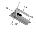
- FIG. 6 is a diagram showing a conventional assembled battery described in Patent Document 1.
- the plurality of battery cells 2 are arranged in a stacked state at a predetermined interval so that the wide surfaces of the batteries face each other.
- End plates 3 are arranged at both ends, and the two end plates are held by a holder member 9 provided to face the side surface of the battery cell 2.
- the battery cell 2 expands during charging and discharging, and the distance between the cells and between the cell and the end plate is reduced.
- the spacing members 10 are connected in parallel.
- the battery mounting space is often limited, and if the size of the assembled battery increases, there is a risk of interference with surrounding parts. Accordingly, it is desirable that the assembled battery has a small elongation during the operation of the battery.
- the present invention solves the above-described conventional problems, and an object of the present invention is to provide an assembled battery capable of suppressing the expansion as a whole even when the battery cell expands.
- the assembled battery of the present invention has a plurality of battery cells arranged in series so that the long side surfaces of the batteries face each other, and both ends thereof are sandwiched by a plurality of divided end plates.
- the pair of end plates has a structure in which at least end plate ends other than the four corners of the assembled battery, that is, inside the positive and negative terminals of the battery are joined to the metal band.
- the reaction force due to the expansion of the battery cell can be alleviated, and the elongation of the entire assembled battery can be kept small. .
- FIG. 1A is a diagram showing a state in which the assembled battery according to Embodiment 1 of the present invention is assembled.
- FIG. 1B is a diagram showing components excluding battery cells in the assembled battery according to Embodiment 1 of the present invention.
- FIG. 1C is a diagram showing a battery cell of the assembled battery according to Embodiment 1 of the present invention.
- FIG. 2A is a diagram illustrating an analysis example when the battery cell expands.
- FIG. 2B is a diagram showing an end plate, a metal band, and a connecting member obtained from the analysis result.
- FIG. 3 is a diagram of an end plate and a connecting member according to Embodiment 3 of the present invention.
- FIG. 4 is a diagram of an end plate according to Embodiment 4 of the present invention.
- FIG. 1A is a diagram showing a state in which the assembled battery according to Embodiment 1 of the present invention is assembled.
- FIG. 1B is a diagram showing components excluding battery cells in the assembled
- FIG. 5A is a diagram showing a dimensional change of the end plate.
- FIG. 5B is a diagram showing a dimensional change of the end plate.
- FIG. 5C is a diagram showing a dimensional change of the end plate.
- FIG. 6 is a diagram showing a battery block of a conventional assembled battery described in Patent Document 1. As shown in FIG.
- FIG. 1A to 1C are overall views of the assembled battery according to Embodiment 1 of the present invention.
- 1A to 1C the same components as those in FIG. 6 are denoted by the same reference numerals, and description thereof is omitted.
- the assembled battery 1 includes a battery cell 2, an end plate 3, a metal band 4, and a connecting member 5.
- 1A shows a state in which the assembled battery 1 is assembled
- FIG. 1B shows the components excluding the battery cell 2
- FIG. 1C shows the battery cell 2.
- the battery cell 2 gradually expands in the process of repeated charge and discharge during use. This is due to the following reason.
- the battery cell 2 is dried after applying a material as an electrode material to a metal foil, and further wound in a compressed state in the thickness direction and sealed in a cell can together with an electrolytic solution.
- the electrode material expands due to heat generated by the electrode chemical reaction or Joule heat.
- the material that has expanded at the beginning of its life will eventually return to its original state, but the residual stress generated during the compression process during production will be gradually released, and as charging and discharging are repeated, the thickness of the electrode will increase and the thickness of the entire battery cell will increase. It will also increase.
- the electrode thickness continues to increase, the electrode will buckle in due to the compression force from the restraint by the cell can.
- the electrolyte in the gap generated by buckling is vaporized even at room temperature, and as the temperature rises, the volume increases and the thickness of the battery cell increases accordingly.
- FIG. 1C there is an electrode terminal at the upper end of the battery cell 2, and the wound electrode was wound as shown by an arrow 7 around the direction of the long dimension of the rectangular battery.
- the battery cell 2 hardly expands in the axial direction of winding, and the battery cell 2 has a gap above the wound electrode group and the cell can on the upper side where the terminal of the battery cell 2 is located.
- the battery cell 2 expands in the direction of a larger area because it hardly expands even during operation.
- the lithium secondary battery cell expands and becomes wide in use.
- the space in which the battery can be mounted is limited, so parts and structures other than the battery are often placed close to each other. There is concern about interfering with. Therefore, the dimensional change of the assembled battery 1 needs to be kept to a minimum.
- a method for increasing the rigidity of the member by increasing the size of the member constituting the assembled battery 1 or using a material having a high Young's modulus and the expansion of the battery cell 2 to the component member.
- the assembled battery tends to be large and heavy, and it is not preferable for in-vehicle applications that require a reduction in size and weight.
- the assembled battery shown in FIG. 1A has a structure that suppresses the increase in size and weight as much as possible.
- a plurality of battery cells 2 are arranged in series so that the surfaces with large areas face each other.
- the end plate 3 is arranged in a pair at both ends thereof, and connects the two plates with two plates each having a height dimension the same as that of the battery cell 2 and a width dimension smaller than the long side of the long side surface of the battery cell 2.
- the connection member 5 is used.
- the two plates are arranged at both ends of the long side surface of the battery cell 2 arranged at the end, and a bolt fastening portion 6 that is fastened to the base is provided at the end opposite to the end surface of the battery cell 2.
- the two plates and the connecting member 5 are joined together by a method such as welding.
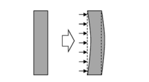
- the surface of the battery cell 2 having a large area at the end has a portion that does not contact the end plate 3 at the center.
- the center of the surface having a large area expands.
- the end plate 3 of the present invention does not come into contact even when the center of the battery cell 2 expands, and the reaction force due to the expansion can be reduced. As a result, the amount of deformation in the long side direction of the entire assembled battery 1 when the battery operates can be smaller than that of a single end plate.
- resin or metal may be used, but it is desirable that the bending elastic modulus is 150 GPa or more.
- the area ratio of the plurality of end plates 3 to the wide surface of the battery cell 2 is desirably 20% or more in total.
- the metal band 4c described later must not interfere with the terminals on the upper part of the battery cell 2, and the end plate 3 needs to have a size that satisfies this.
- the pair of end plates 3 are fastened to each other with a metal band 4.
- the metal band 4 plays a role of suppressing the entire assembled battery 1 from being extended by a reaction force generated by the expansion of the battery cell 2.
- it is required to have a high longitudinal elastic modulus like high-tensile steel.
- the configuration of the metal band 4 is such that two short side surfaces of the assembled battery 1 are connected to each other on the side surface of the metal band 4a and below the side surface of the metal band 4b.
- the top surface of the metal band 4c and the bottom surface of the metal band 4d are each two, that is, the assembled battery 1 as a whole has a total of eight.
- FIG. 2A shows a model used for the analysis, and shows a state where the assembled battery 1 is attached to the base, excluding the battery cell 2.
- the battery pack 1 has a symmetrical shape in the central section in the longitudinal direction and the lateral direction, a quarter of the whole is modeled, and the symmetry plane is a boundary that restrains displacement in a direction perpendicular to the symmetry plane.
- the analysis is equivalent to what is modeled and analyzed as a whole.
- FIG. 2B is a modified view of the end plate 3, the metal band 4, and the connecting member 5 obtained from the analysis.
- the displacement of the end plate 3 is small because the lower side is fixed by bolt fastening, and the displacement is larger than the lower side because there is no such restriction on the upper side.
- the battery cell is installed at least on the top surface of the metal band 4c.
- the upper side of the end plate 3 can also be restrained by any method, for example, by providing a base and fastening it.
- the bottom surface of the metal band 4d has a role of reducing the longitudinal displacement of the assembled battery 1 like the other metal bands 4, and prevents the dropping by supporting the battery cell 2 when the assembled battery 1 is assembled. It also has a function. Regarding this function, the metal band 4b on the lower side of the short side surface can be substituted by making the lower side surface of the metal band 4b L-shaped and supporting it at both ends of the battery cell 2. In this case, if the assembled battery 1 is used by being bolted to some base, the displacement on the lower side of the assembled battery 1 can be made almost zero, so there is no problem even if the bottom surface of the metal band 4d is not provided.
- the end plate 3 may not be divided into two upper and lower sides on both short sides, but may be an integral unit in which the upper and lower sides are coupled as shown in FIGS. 2A to 2B.
- the end plate 3 When it is necessary to suppress the temperature rise of the battery cell 2 during the operation of the battery pack 1, and it is cooled by blowing air through the gaps between the battery cells 2 arranged in series, it is better to divide the battery cell into two upper and lower parts.
- the short side surface does not require a cooling mechanism, and may be a single body.
- the connecting parts are U-shaped parts as shown in FIG.
- the end plate 3 is provided with a connecting member insertion hole 8 into which the connecting part is fitted, and the connecting part is fitted into this part during assembly.
- the jig for assembling the assembled battery 1 is used for positioning the connecting member insertion hole 8 of the end plate shown in FIG. 4, it can be assembled without connecting parts.
- FIG. 5A shows the surface on the opposite side which contact
- FIG. 5C shows the inside of the end plate viewed from the side.
- the end plate 3 is a rectangular parallelepiped, and has a rectangular shape as shown in FIG. 5B when viewed from the inner side surface.
- the end plate 3 is pushed by the reaction force due to the expansion of the battery cell 2, the displacement at the center is the largest.
- the assembled battery of the present invention can also be applied to transportation equipment such as an electric vehicle and a hybrid vehicle, or a storage battery for home use, an emergency storage power source, and the like.
Landscapes
- Engineering & Computer Science (AREA)
- Manufacturing & Machinery (AREA)
- Chemical & Material Sciences (AREA)
- Chemical Kinetics & Catalysis (AREA)
- Electrochemistry (AREA)
- General Chemical & Material Sciences (AREA)
- Battery Mounting, Suspending (AREA)
Abstract
Description
図1A~図1Cは本発明の実施の形態1における組電池の全体図である。図1A~図1Cにおいて、図6と同じ構成要素については同じ符号を用い、説明を省略する。
また、エンドプレート3は、例えば両短側面は上下二本に分かれていなくても、図2A~図2Bに示すように上下が結合された一体物としてもよい。組電池1の動作中に電池セル2の温度上昇を抑制する必要があり、直列に並んだ電池セル2の隙間に風を通して冷やすような場合には上下二本に分かれている方が良い。
組電池1の両方の長側面端にある2つのエンドプレート3と連結部品について、連結部品を図4に示すような、コの字型部品とする。エンドプレート3には、図4に示すような、連結部品をはめ込む連結部材挿入穴8を設け、組立時にはこの部分に連結部品をはめ込んでおく。
エンドプレート3について、図5Aに示すように、電池セル2と接する反対側の面、すなわち、組電池1の長側面最外周側の表面を削り、窪んだ形状にする。このエンドプレート内側を側面から見たものが図5Cである。
2 電池セル
3 エンドプレート
4,4a,4b,4c,4d 金属バンド
5 連結部材
6 ボルト締結部
8 連結部材挿入穴
9 ホルダ部材
10 間隔保持部材
Claims (6)
- 複数の電池セルが直列に並び、両端を一対のエンドプレートで挟み、前記一対のエンドプレートが金属バンドで締結される組電池において、
前記一対のエンドプレートはそれぞれ複数の小プレートで構成され、前記複数の小プレートのうち、一方に配置される小プレートAと、前記複数の電池セルを挟んで対向して配置される他方の小プレートBとが、第1金属バンドで接合されてなること、
を特徴とする組電池。 - 前記一方に配置される小プレートAの内側端部と、前記他方の小プレートBの内側端部とが前記第1金属バンドで接合されてなる、請求項1記載の組電池。
- 前記小プレートAと前記小プレートBとは、同一形状である、請求項1または2に記載の組電池。
- 前記一対のエンドプレートのそれぞれ複数の小プレートは、連結部材で締結されてなり、前記連結部材は着脱可能に構成される、請求項1~3の何れか一項に記載の組電池。
- 前記一方に配置される小プレートAと前記他方の小プレートBとは、前記第1金属バンドが配設される面の側面の前記複数の電池セルが積層される方向において、更に第2金属バンドで接合されてなる、請求項1~4の何れか一項に記載の組電池。
- 前記第2金属バンドは、複数の部材で構成される、請求項5記載の組電池。
Priority Applications (3)
| Application Number | Priority Date | Filing Date | Title |
|---|---|---|---|
| JP2017512199A JP6735451B2 (ja) | 2015-04-16 | 2016-04-13 | 組電池 |
| EP16779768.7A EP3285310B1 (en) | 2015-04-16 | 2016-04-13 | Assembled battery |
| US15/317,712 US9819047B2 (en) | 2015-04-16 | 2016-04-13 | Assembled battery |
Applications Claiming Priority (2)
| Application Number | Priority Date | Filing Date | Title |
|---|---|---|---|
| JP2015083826 | 2015-04-16 | ||
| JP2015-083826 | 2015-04-16 |
Publications (1)
| Publication Number | Publication Date |
|---|---|
| WO2016166972A1 true WO2016166972A1 (ja) | 2016-10-20 |
Family
ID=57126448
Family Applications (1)
| Application Number | Title | Priority Date | Filing Date |
|---|---|---|---|
| PCT/JP2016/001995 Ceased WO2016166972A1 (ja) | 2015-04-16 | 2016-04-13 | 組電池 |
Country Status (4)
| Country | Link |
|---|---|
| US (1) | US9819047B2 (ja) |
| EP (1) | EP3285310B1 (ja) |
| JP (1) | JP6735451B2 (ja) |
| WO (1) | WO2016166972A1 (ja) |
Cited By (11)
| Publication number | Priority date | Publication date | Assignee | Title |
|---|---|---|---|---|
| WO2019021778A1 (ja) * | 2017-07-27 | 2019-01-31 | 三洋電機株式会社 | 電池モジュール及びこれを装備する車両 |
| JP2019194957A (ja) * | 2018-05-02 | 2019-11-07 | トヨタ自動車株式会社 | 組電池 |
| WO2020059296A1 (ja) * | 2018-09-20 | 2020-03-26 | 三洋電機株式会社 | 電源装置及び電源装置を備える車両並びに蓄電装置 |
| US11616265B2 (en) | 2018-10-19 | 2023-03-28 | Samsung Sdi Co., Ltd. | Battery module |
| US11626630B2 (en) | 2018-10-19 | 2023-04-11 | Samsung Sdi Co., Ltd. | Battery module |
| US11637339B2 (en) | 2018-10-19 | 2023-04-25 | Samsung Sdi Co., Ltd. | Battery module |
| JP2023528791A (ja) * | 2020-12-29 | 2023-07-06 | エルジー エナジー ソリューション リミテッド | スウェリング吸収可能な構造を有するバッテリーモジュール及びそれを含むバッテリーパック、並びに自動車 |
| US11862778B2 (en) | 2018-10-19 | 2024-01-02 | Samsung Sdi Co., Ltd. | Battery module |
| US11876243B2 (en) | 2018-10-19 | 2024-01-16 | Samsung Sdi Co., Ltd. | Battery module |
| US11901529B2 (en) | 2018-10-19 | 2024-02-13 | Samsung Sdi Co., Ltd. | Battery module |
| US12614801B2 (en) | 2020-12-29 | 2026-04-28 | Lg Energy Solution, Ltd. | Battery module having structure capable of absorbing swelling, and battery pack and vehicle comprising same |
Families Citing this family (3)
| Publication number | Priority date | Publication date | Assignee | Title |
|---|---|---|---|---|
| KR102365631B1 (ko) * | 2018-01-09 | 2022-02-21 | 주식회사 엘지에너지솔루션 | 배터리 모듈 |
| CN114583370B (zh) | 2019-12-31 | 2024-01-30 | 宁德时代新能源科技股份有限公司 | 电池模块、电池组、装置及电池模块的装配方法 |
| DE102023206993A1 (de) | 2023-07-24 | 2025-01-30 | Volkswagen Aktiengesellschaft | Prismatische Batteriezelle |
Citations (11)
| Publication number | Priority date | Publication date | Assignee | Title |
|---|---|---|---|---|
| JPH08250151A (ja) * | 1995-03-14 | 1996-09-27 | Matsushita Electric Ind Co Ltd | 密閉形アルカリ蓄電池の単位電池 |
| JP2006012841A (ja) * | 2004-06-25 | 2006-01-12 | Samsung Sdi Co Ltd | 二次電池モジュール |
| JP2006108058A (ja) * | 2004-10-08 | 2006-04-20 | Toyota Motor Corp | 燃料電池スタックとその製造方法ならびに製造装置 |
| JP2010092610A (ja) * | 2008-10-03 | 2010-04-22 | Toyota Motor Corp | 組電池構造体、車両、電池搭載機器及び組電池構造体の製造方法 |
| WO2010090003A1 (ja) * | 2009-02-05 | 2010-08-12 | パナソニック株式会社 | 高分子電解質型燃料電池スタック |
| JP2010257650A (ja) * | 2009-04-22 | 2010-11-11 | Toyota Motor Corp | バッテリパック |
| WO2012013789A1 (fr) * | 2010-07-29 | 2012-02-02 | E4V | Système de refroidissement de batterie électrique et batterie comprenant un tel système |
| JP2012204081A (ja) * | 2011-03-24 | 2012-10-22 | Denso Corp | 電池パック |
| JP2013054869A (ja) * | 2011-09-01 | 2013-03-21 | Toshiba Corp | 組電池およびその製造方法 |
| WO2013146561A1 (ja) * | 2012-03-28 | 2013-10-03 | 三洋電機株式会社 | 電源装置及びこれを備える車両並びに蓄電装置 |
| JP2015084292A (ja) * | 2013-10-25 | 2015-04-30 | パナソニックIpマネジメント株式会社 | 燃料電池スタック |
Family Cites Families (5)
| Publication number | Priority date | Publication date | Assignee | Title |
|---|---|---|---|---|
| JP5490652B2 (ja) | 2010-09-10 | 2014-05-14 | タイガースポリマー株式会社 | 組電池構造 |
| JP5501286B2 (ja) * | 2011-04-28 | 2014-05-21 | 日立ビークルエナジー株式会社 | 蓄電装置 |
| KR20140032165A (ko) * | 2012-09-06 | 2014-03-14 | 현대자동차주식회사 | 전기자동차 배터리모듈 안전장치 |
| WO2014125605A1 (ja) * | 2013-02-15 | 2014-08-21 | 日立オートモティブシステムズ株式会社 | 二次電池モジュール |
| JP6028231B2 (ja) * | 2014-04-11 | 2016-11-16 | パナソニックIpマネジメント株式会社 | 組電池 |
-
2016
- 2016-04-13 JP JP2017512199A patent/JP6735451B2/ja active Active
- 2016-04-13 EP EP16779768.7A patent/EP3285310B1/en active Active
- 2016-04-13 WO PCT/JP2016/001995 patent/WO2016166972A1/ja not_active Ceased
- 2016-04-13 US US15/317,712 patent/US9819047B2/en active Active
Patent Citations (11)
| Publication number | Priority date | Publication date | Assignee | Title |
|---|---|---|---|---|
| JPH08250151A (ja) * | 1995-03-14 | 1996-09-27 | Matsushita Electric Ind Co Ltd | 密閉形アルカリ蓄電池の単位電池 |
| JP2006012841A (ja) * | 2004-06-25 | 2006-01-12 | Samsung Sdi Co Ltd | 二次電池モジュール |
| JP2006108058A (ja) * | 2004-10-08 | 2006-04-20 | Toyota Motor Corp | 燃料電池スタックとその製造方法ならびに製造装置 |
| JP2010092610A (ja) * | 2008-10-03 | 2010-04-22 | Toyota Motor Corp | 組電池構造体、車両、電池搭載機器及び組電池構造体の製造方法 |
| WO2010090003A1 (ja) * | 2009-02-05 | 2010-08-12 | パナソニック株式会社 | 高分子電解質型燃料電池スタック |
| JP2010257650A (ja) * | 2009-04-22 | 2010-11-11 | Toyota Motor Corp | バッテリパック |
| WO2012013789A1 (fr) * | 2010-07-29 | 2012-02-02 | E4V | Système de refroidissement de batterie électrique et batterie comprenant un tel système |
| JP2012204081A (ja) * | 2011-03-24 | 2012-10-22 | Denso Corp | 電池パック |
| JP2013054869A (ja) * | 2011-09-01 | 2013-03-21 | Toshiba Corp | 組電池およびその製造方法 |
| WO2013146561A1 (ja) * | 2012-03-28 | 2013-10-03 | 三洋電機株式会社 | 電源装置及びこれを備える車両並びに蓄電装置 |
| JP2015084292A (ja) * | 2013-10-25 | 2015-04-30 | パナソニックIpマネジメント株式会社 | 燃料電池スタック |
Non-Patent Citations (1)
| Title |
|---|
| See also references of EP3285310A4 * |
Cited By (19)
| Publication number | Priority date | Publication date | Assignee | Title |
|---|---|---|---|---|
| WO2019021778A1 (ja) * | 2017-07-27 | 2019-01-31 | 三洋電機株式会社 | 電池モジュール及びこれを装備する車両 |
| JP2019194957A (ja) * | 2018-05-02 | 2019-11-07 | トヨタ自動車株式会社 | 組電池 |
| JP7033255B2 (ja) | 2018-05-02 | 2022-03-10 | トヨタ自動車株式会社 | 組電池 |
| WO2020059296A1 (ja) * | 2018-09-20 | 2020-03-26 | 三洋電機株式会社 | 電源装置及び電源装置を備える車両並びに蓄電装置 |
| JPWO2020059296A1 (ja) * | 2018-09-20 | 2021-09-30 | 三洋電機株式会社 | 電源装置及び電源装置を備える車両並びに蓄電装置 |
| JP7225257B2 (ja) | 2018-09-20 | 2023-02-20 | 三洋電機株式会社 | 電源装置及び電源装置を備える車両並びに蓄電装置 |
| US11637339B2 (en) | 2018-10-19 | 2023-04-25 | Samsung Sdi Co., Ltd. | Battery module |
| US11626630B2 (en) | 2018-10-19 | 2023-04-11 | Samsung Sdi Co., Ltd. | Battery module |
| US11616265B2 (en) | 2018-10-19 | 2023-03-28 | Samsung Sdi Co., Ltd. | Battery module |
| US11862778B2 (en) | 2018-10-19 | 2024-01-02 | Samsung Sdi Co., Ltd. | Battery module |
| US11876243B2 (en) | 2018-10-19 | 2024-01-16 | Samsung Sdi Co., Ltd. | Battery module |
| US11901529B2 (en) | 2018-10-19 | 2024-02-13 | Samsung Sdi Co., Ltd. | Battery module |
| US12046735B2 (en) | 2018-10-19 | 2024-07-23 | Samsung Sdi Co., Ltd. | Battery module |
| US12288860B2 (en) | 2018-10-19 | 2025-04-29 | Samsung Sdi Co., Ltd. | Battery module |
| US12362409B2 (en) | 2018-10-19 | 2025-07-15 | Samsung Sdi Co., Ltd. | Battery module |
| US12412946B2 (en) | 2018-10-19 | 2025-09-09 | Samsung Sdi Co., Ltd. | Battery module |
| JP2023528791A (ja) * | 2020-12-29 | 2023-07-06 | エルジー エナジー ソリューション リミテッド | スウェリング吸収可能な構造を有するバッテリーモジュール及びそれを含むバッテリーパック、並びに自動車 |
| JP7566043B2 (ja) | 2020-12-29 | 2024-10-11 | エルジー エナジー ソリューション リミテッド | スウェリング吸収可能な構造を有するバッテリーモジュール及びそれを含むバッテリーパック、並びに自動車 |
| US12614801B2 (en) | 2020-12-29 | 2026-04-28 | Lg Energy Solution, Ltd. | Battery module having structure capable of absorbing swelling, and battery pack and vehicle comprising same |
Also Published As
| Publication number | Publication date |
|---|---|
| US20170133706A1 (en) | 2017-05-11 |
| JP6735451B2 (ja) | 2020-08-05 |
| JPWO2016166972A1 (ja) | 2018-02-08 |
| EP3285310B1 (en) | 2020-03-11 |
| EP3285310A1 (en) | 2018-02-21 |
| EP3285310A4 (en) | 2018-02-21 |
| US9819047B2 (en) | 2017-11-14 |
Similar Documents
| Publication | Publication Date | Title |
|---|---|---|
| JP6735451B2 (ja) | 組電池 | |
| US11329347B2 (en) | Battery pack and vehicle | |
| US10199676B2 (en) | Secondary battery pack comprising movable wall and elastic member | |
| JP5605252B2 (ja) | 蓄電装置 | |
| US8557428B2 (en) | Battery module and battery pack including the same | |
| US11251493B2 (en) | Battery pack | |
| JP5472059B2 (ja) | 蓄電装置 | |
| KR102102101B1 (ko) | 조전지 | |
| KR102740937B1 (ko) | 면압이 적용된 배터리 모듈 및 이를 갖는 배터리 팩 | |
| JP6636035B2 (ja) | 電池圧縮阻止体及びそれを含む電池モジュール | |
| JP2017212120A (ja) | バッテリ | |
| JP5903564B2 (ja) | 組電池 | |
| US20170033339A1 (en) | Electricity storage system | |
| JP2017098107A (ja) | 蓄電装置 | |
| JP5867582B2 (ja) | 蓄電装置 | |
| JPWO2019021777A1 (ja) | 電池モジュール及びこれを装備する車両 | |
| JP5724921B2 (ja) | 拘束機構の強度設定方法および蓄電装置 | |
| JP2008235149A (ja) | 組電池用スペーサ部材及び組電池 | |
| JPWO2018230390A1 (ja) | 蓄電装置 | |
| US20220294069A1 (en) | Buffer member and electrical storage module | |
| JP2018060755A (ja) | 組電池 | |
| KR101864918B1 (ko) | 배터리 모듈 및 배터리 모듈 제조방법 | |
| CN209447862U (zh) | 一种端板、电池模块及电池包 | |
| JP3254503U (ja) | バッテリーモジュール化のためのエンドプレート構造 | |
| US20250349959A1 (en) | Battery system with deformable end plate |
Legal Events
| Date | Code | Title | Description |
|---|---|---|---|
| 121 | Ep: the epo has been informed by wipo that ep was designated in this application |
Ref document number: 16779768 Country of ref document: EP Kind code of ref document: A1 |
|
| WWE | Wipo information: entry into national phase |
Ref document number: 15317712 Country of ref document: US |
|
| REEP | Request for entry into the european phase |
Ref document number: 2016779768 Country of ref document: EP |
|
| ENP | Entry into the national phase |
Ref document number: 2017512199 Country of ref document: JP Kind code of ref document: A |
|
| NENP | Non-entry into the national phase |
Ref country code: DE |
|
| WWE | Wipo information: entry into national phase |
Ref document number: 2016779768 Country of ref document: EP |