WO2016167059A1 - Plaque de polarisation et son procédé de production - Google Patents
Plaque de polarisation et son procédé de production Download PDFInfo
- Publication number
- WO2016167059A1 WO2016167059A1 PCT/JP2016/057494 JP2016057494W WO2016167059A1 WO 2016167059 A1 WO2016167059 A1 WO 2016167059A1 JP 2016057494 W JP2016057494 W JP 2016057494W WO 2016167059 A1 WO2016167059 A1 WO 2016167059A1
- Authority
- WO
- WIPO (PCT)
- Prior art keywords
- polarizer
- polarizing plate
- gap
- treatment liquid
- manufacturing
- Prior art date
- Legal status (The legal status is an assumption and is not a legal conclusion. Google has not performed a legal analysis and makes no representation as to the accuracy of the status listed.)
- Ceased
Links
Images

Classifications
-
- G—PHYSICS
- G02—OPTICS
- G02B—OPTICAL ELEMENTS, SYSTEMS OR APPARATUS
- G02B5/00—Optical elements other than lenses
- G02B5/30—Polarising elements
-
- G—PHYSICS
- G02—OPTICS
- G02B—OPTICAL ELEMENTS, SYSTEMS OR APPARATUS
- G02B5/00—Optical elements other than lenses
- G02B5/30—Polarising elements
- G02B5/3025—Polarisers, i.e. arrangements capable of producing a definite output polarisation state from an unpolarised input state
-
- G—PHYSICS
- G02—OPTICS
- G02B—OPTICAL ELEMENTS, SYSTEMS OR APPARATUS
- G02B1/00—Optical elements characterised by the material of which they are made; Optical coatings for optical elements
- G02B1/10—Optical coatings produced by application to, or surface treatment of, optical elements
-
- G—PHYSICS
- G02—OPTICS
- G02B—OPTICAL ELEMENTS, SYSTEMS OR APPARATUS
- G02B5/00—Optical elements other than lenses
- G02B5/30—Polarising elements
- G02B5/3025—Polarisers, i.e. arrangements capable of producing a definite output polarisation state from an unpolarised input state
- G02B5/3033—Polarisers, i.e. arrangements capable of producing a definite output polarisation state from an unpolarised input state in the form of a thin sheet or foil, e.g. Polaroid
-
- G—PHYSICS
- G02—OPTICS
- G02F—OPTICAL DEVICES OR ARRANGEMENTS FOR THE CONTROL OF LIGHT BY MODIFICATION OF THE OPTICAL PROPERTIES OF THE MEDIA OF THE ELEMENTS INVOLVED THEREIN; NON-LINEAR OPTICS; FREQUENCY-CHANGING OF LIGHT; OPTICAL LOGIC ELEMENTS; OPTICAL ANALOGUE/DIGITAL CONVERTERS
- G02F1/00—Devices or arrangements for the control of the intensity, colour, phase, polarisation or direction of light arriving from an independent light source, e.g. switching, gating or modulating; Non-linear optics
- G02F1/01—Devices or arrangements for the control of the intensity, colour, phase, polarisation or direction of light arriving from an independent light source, e.g. switching, gating or modulating; Non-linear optics for the control of the intensity, phase, polarisation or colour
- G02F1/13—Devices or arrangements for the control of the intensity, colour, phase, polarisation or direction of light arriving from an independent light source, e.g. switching, gating or modulating; Non-linear optics for the control of the intensity, phase, polarisation or colour based on liquid crystals, e.g. single liquid crystal display cells
- G02F1/133—Constructional arrangements; Operation of liquid crystal cells; Circuit arrangements
- G02F1/1333—Constructional arrangements; Manufacturing methods
- G02F1/1335—Structural association of cells with optical devices, e.g. polarisers or reflectors
- G02F1/133528—Polarisers
-
- G—PHYSICS
- G02—OPTICS
- G02B—OPTICAL ELEMENTS, SYSTEMS OR APPARATUS
- G02B1/00—Optical elements characterised by the material of which they are made; Optical coatings for optical elements
- G02B1/10—Optical coatings produced by application to, or surface treatment of, optical elements
- G02B1/14—Protective coatings, e.g. hard coatings
Definitions
- the present invention relates to a polarizing plate and a manufacturing method thereof.
- a polarizing plate is used in an image display device (for example, a liquid crystal display device) such as a mobile phone or a notebook personal computer.
- an image display device for example, a liquid crystal display device
- a problem of durability is likely to occur.
- a polarizing plate having an outer peripheral end surface formed by solidification after melting has been proposed (see Patent Document 1), but further improvement in durability is required.
- the present invention has been made in order to solve the above-mentioned problems, and its main purpose is to provide a polarizing plate having excellent durability.
- the polarizing plate of the present invention has a polarizer and a pair of protective films respectively disposed on both main surfaces of the polarizer, and the end face of the polarizer is inward in the plane direction from the end face of the protective film. It has a polarizer gap formed in a position.
- gap part is formed over the position of 15 micrometers or more in the surface direction inward from the end surface of the said protective film.
- the polarizer gap is formed at the end of the polarizer in the absorption axis direction.
- a through hole is formed, and the polarizer gap is formed at the peripheral edge of the through hole. In one embodiment, the polarizer gap is formed at the outer edge.
- the said outer edge contains the site
- the manufacturing method of the said polarizing plate includes a step of bringing a treatment liquid into contact with a laminate obtained by laminating protective films on both principal surfaces of a polarizer.
- the treatment liquid includes water.
- the liquid temperature of the said processing liquid is 50 degreeC or more.
- the process includes the step of forming the laminate into a desired shape by cutting and / or punching.
- the cutting and / or punching process is performed by irradiating a laser beam.
- the laser is a CO 2 laser.
- a polarizing plate having extremely excellent durability can be obtained by having a polarizer gap formed by positioning the end face of the polarizer in the plane direction inward from the end face of the protective film. .
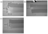
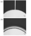
- FIG. 1 is a plan view of a polarizing plate according to one embodiment of the present invention. It is an expanded sectional view of the edge part of the polarizing plate shown in FIG. (A) is the observation photograph by the optical microscope of the edge part (MD direction) of the polarizing plate of Example 1, (b) is the observation photograph by the optical microscope of the edge part (TD direction) of Example 1. (C) is an observation photograph of the end of the polarizing plate of Comparative Example 1 with an optical microscope. (A) is a photograph which shows the external appearance of the polarizing plate of the comparative example 3 after a heat cycle test, (b) is a photograph which shows the external appearance of the polarizing plate of Example 3 after a heat cycle test.
- FIG. 1 is a plan view of a polarizing plate according to one embodiment of the present invention
- FIG. 2 is an enlarged cross-sectional view of an end portion of the polarizing plate shown in FIG.
- the polarizing plate 100 is suitably used for an automobile meter panel.
- the polarizing plate 100 is configured by connecting a first display unit 50 and a second display unit 60, and through holes 51 and 61 for fixing various meter needles are provided near the center of each display unit. Each is formed.
- the diameter of the through hole is, for example, 0.5 mm to 100 mm.
- the outer edges of the display units 50 and 60 are formed in an arc shape along the rotation direction of the meter needle.
- the polarizing plate 100 includes a polarizer 10 and a pair of protective films 21 and 22 disposed on both main surfaces of the polarizer 10, respectively.
- the polarizing plate 100 has the end face 10a of the polarizer 10 from the end faces 21a and 22a of the protective films 21 and 22 at the end portions (specifically, the outer edge portion 101 and the peripheral portions 51a and 61a of the through holes 51 and 61).
- the durability can be improved by forming the polarizer gap. Specifically, the generation of cracks can be suppressed.
- a polarizer has a contraction force larger than that of a protective film, and a stress may be generated at the interface between the polarizer and the protective film due to a change in temperature and humidity, thereby generating a crack. It is considered that this stress can be relaxed by forming the polarizer gap. Therefore, the occurrence of cracks can be effectively suppressed by forming the polarizer gap in a portion where stress is likely to concentrate, such as a periphery of a through-hole described later or a V-shaped portion. Moreover, according to such a form, there is very little influence which it has on external appearance and bonding with another member.
- the position of the through hole can be appropriately set according to the use of the polarizing plate, for example.
- the crack is likely to be generated starting from the periphery of the through hole, and the tendency of the crack becomes more prominent as the position of the through hole is away from the outer edge of the polarizing plate.
- the effect of improving the durability due to the formation of the polarizer gap portion can be significantly obtained.
- the polarizer gap is preferably formed at least at the boundary portions 41 and 42 of each display portion. Specifically, the polarizer gap is preferably formed at a site where the outer edge forms a V-shape (including a round shape) convex inward in the plane direction. This is because the portion where the outer edge has a V-shape projecting inwardly in the surface direction is likely to be the starting point of a crack, similar to the periphery of the through hole.
- the polarizer gap is preferably formed at the end of the polarizer in the absorption axis direction.
- the cracks tend to occur along the absorption axis direction of the polarizer, and the formation of the cracks in the absorption axis direction can effectively suppress the generation of cracks.
- the polarizer gap is preferably formed over a position of 15 ⁇ m or more inward in the plane direction from the end face of the protective film, more preferably over a position of 20 ⁇ m or more. If it is such a range, the effect of the said durability improvement can fully be acquired.
- the polarizer gap is preferably formed from the end face of the protective film to the position of 1000 ⁇ m or less inward in the plane direction, more preferably 500 ⁇ m or less, and even more preferably 300 ⁇ m or less.
- gap part is easier to form the absorption-axis direction edge part than other directions (for example, transmission axis direction).
- the polarizing plate of the present invention is not limited to the configuration of the illustrated example, and can be changed as appropriate.
- the shape of the polarizing plate, the presence / absence of the through hole, the shape and size of the through hole, the number of the through holes and the formation position can be appropriately changed.
- the polarizer is typically composed of a resin film containing a dichroic substance.
- the dichroic substance include iodine and organic dyes. These may be used alone or in combination of two or more. Preferably, iodine is used.
- any appropriate resin can be used as the resin forming the resin film.
- a hydrophilic resin for example, polyvinyl alcohol (PVA) resin
- PVA resin include polyvinyl alcohol and ethylene-vinyl alcohol copolymer.
- Polyvinyl alcohol is obtained by saponifying polyvinyl acetate.
- the ethylene-vinyl alcohol copolymer can be obtained by saponifying an ethylene-vinyl acetate copolymer.
- the degree of saponification of the PVA-based resin is usually 85 to 100 mol%, preferably 95.0 mol% or more, more preferably 99.0 mol% or more, and particularly preferably 99.93 mol% or more. .
- the degree of saponification can be determined according to JIS K 6726-1994. By using a PVA-based resin having such a saponification degree, a polarizer having excellent durability can be obtained.
- the average degree of polymerization of the PVA resin can be appropriately selected according to the purpose.
- the average degree of polymerization is usually 1000 to 10000, preferably 1200 to 6000, more preferably 2000 to 5000.
- the average degree of polymerization can be determined according to JIS K 6726-1994.
- the polarizer preferably exhibits absorption dichroism in the wavelength range of 380 nm to 780 nm.
- the single transmittance (Ts) of the polarizer is preferably 40% or more, more preferably 41% or more, still more preferably 42% or more, and particularly preferably 43% or more.
- the theoretical upper limit of the single transmittance is 50%, and the practical upper limit is 46%.
- the single transmittance (Ts) is a Y value measured with a 2 degree visual field (C light source) of JIS Z8701 and corrected for visibility, for example, using a spectrophotometer (manufactured by JASCO, V7100). Can be measured.
- the polarization degree of the polarizer is preferably 99.8% or more, more preferably 99.9% or more, and further preferably 99.95% or more.
- the thickness of the polarizer can be set to any appropriate value.
- the thickness is typically 1 ⁇ m to 80 ⁇ m, preferably 3 ⁇ m to 40 ⁇ m.
- the polarizer can be typically obtained by subjecting the resin film to treatment such as swelling treatment, stretching treatment, dyeing treatment with the dichroic substance, crosslinking treatment, washing treatment, and drying treatment.
- treatment such as swelling treatment, stretching treatment, dyeing treatment with the dichroic substance, crosslinking treatment, washing treatment, and drying treatment.
- the number, order, timing, and the like of each process can be set as appropriate.
- the resin film may be a resin layer formed on a substrate.
- the cross-linking treatment is performed, for example, by bringing a resin film into contact with a boric acid solution (for example, a boric acid aqueous solution).
- a boric acid solution for example, a boric acid aqueous solution.
- stretch it is preferable to extend
- the stretching direction in the stretching treatment can correspond to the absorption axis direction of the obtained polarizer. From the viewpoint of obtaining excellent polarization characteristics, the resin film is usually uniaxially stretched 3 to 7 times.
- the polarizer has a low concentration adjacent to the above-described polarizer gap (at the end in the surface direction of the resin film), and the content concentration of the component contained in the resin film is lower than that of other portions.
- the part is formed.
- the component contained in the solution for example, the solution which dissolved iodides, such as potassium iodide, for example
- boric acid a dichroic substance, and said various processes
- the durability can be further improved.
- the low-concentration portion can have a lower rigidity than other sites by releasing the cross-linking structure of the above component (typically boric acid). As a result, in the low concentration portion, the stress due to the polarizer contraction is relaxed, and the generation of cracks can be suppressed.
- the rigidity can be lower than other parts by releasing the crosslinked structure by boric acid, the occurrence of cracks is suppressed, while the heat resistance is lowered. Can do.
- One of the causes is that the content of iodine complexes (eg, I 3 ⁇ , I 5 ⁇ ) is low and the content of iodine ions (eg, I ⁇ , I 3 ⁇ ) is low in the low concentration part of boric acid. It can be expensive.
- the iodine complex can be oriented in the resin film, while iodine ions can be present in the resin film in an unstable state.
- a substance that forms a counter ion of iodine for example, potassium and / or sodium
- the iodine ion is stabilized and the heat resistance of the resin film is improved (for example, polyeneization).
- the coloration of the resin film due to the suppression of the above can be suppressed).
- a high concentration portion in which the content concentration of the substance that forms the counter ion of iodine is higher than other portions is formed in the resin film. A form is mentioned.
- Protective film examples of the material for forming the protective film include cellulose resins such as diacetyl cellulose and triacetyl cellulose (TAC), (meth) acrylic resins, cycloolefin resins, olefin resins such as polypropylene, and polyethylene terephthalate systems. Examples thereof include ester resins such as resins, polyamide resins, polycarbonate resins, and copolymer resins thereof.
- the “(meth) acrylic resin” refers to an acrylic resin and / or a methacrylic resin.
- the thickness of the protective film is preferably 10 ⁇ m to 200 ⁇ m.
- a surface treatment layer may be formed on one side of the protective film (side where the polarizer is not disposed). Specifically, a hard coat treatment, an antireflection treatment, or treatment for diffusion or antiglare may be performed.
- the same structure may be sufficient as the structure (formation material, thickness, etc.) of a pair of said protective film, and a different structure may be sufficient as it.
- the protective film is typically laminated on the polarizer surface via an adhesive layer.
- Any appropriate adhesive is used as the adhesive.
- a water-based adhesive, a solvent-based adhesive, an active energy ray curable adhesive, or the like is used as the water-based adhesive.
- an adhesive containing a PVA-based resin is preferably used as the water-based adhesive.
- the polarizing plate is formed into a desired shape by cutting and / or punching a laminate obtained by laminating protective films on both main surfaces of the polarizer. Then, it is manufactured by forming the polarizer gap.
- Cutting (punching) Any appropriate method can be adopted as the cutting (punching) method. Examples thereof include a method using a cutting blade (punching die) such as a Thomson blade and a picnal blade, and a method of irradiating a laser beam. Preferably, cutting by laser light irradiation is employed. According to the laser light irradiation, a smooth cut surface can be obtained, and the occurrence of crack starting points (initial cracks) can be suppressed.
- a cutting blade punching die
- a method of irradiating a laser beam Preferably, cutting by laser light irradiation is employed. According to the laser light irradiation, a smooth cut surface can be obtained, and the occurrence of crack starting points (initial cracks) can be suppressed.
- any appropriate laser can be adopted as the laser as long as the laminate (polarizing plate) can be cut.
- a laser capable of emitting light having a wavelength in the range of 150 nm to 11 ⁇ m is used.
- a gas laser such as a CO 2 laser
- a solid laser such as a YAG laser
- a semiconductor laser Preferably, a CO 2 laser is used.
- the irradiation condition of the laser beam can be set to any appropriate condition depending on, for example, the laser to be used.
- the output condition is preferably 10 W to 1000 W, and more preferably 100 W to 400 W.
- a polarizer gap is formed, for example, by bringing a treatment liquid into contact with the laminate.
- gap part can be simply formed in a desired site
- the constituent components of the polarizer for example, boric acid, dichroic substance, iodine compound, resin film, etc.
- the polarizer gap can be formed satisfactorily.
- the said low concentration part can be formed simultaneously.
- Any appropriate method can be adopted as a method for contacting the treatment liquid. Specific examples include a method of immersing the laminate in the treatment liquid, a method of applying the treatment liquid to the laminate, and a method of spraying the treatment liquid on the laminate. Preferably, a method of immersing the laminate in the treatment liquid is employed.
- the treatment liquid examples include water, alcohols such as methanol and ethanol, dimethyl sulfoxide, dimethylformamide, dimethylacetamide, N-methylpyrrolidone, various glycols, polyhydric alcohols such as trimethylolpropane, ethylenediamine, and diethylenetriamine. Amines are used. These may be used alone or in combination of two or more. Among these, water is preferably used.
- the treatment liquid may contain a substance that forms a counter ion of iodine.
- the treatment liquid is typically a solution in which a compound containing a substance that forms a counter ion of iodine is dissolved in the solvent.
- potassium iodide and / or sodium chloride is preferably used as the compound containing a substance that forms the counter ion of iodine.
- the compounding amount of such a compound is preferably 0.1 to 10 parts by weight, more preferably 1 to 5 parts by weight with respect to 100 parts by weight of the solvent.
- the treatment liquid is a basic solution.
- the treatment liquid can be obtained by blending a basic compound with the solvent.
- the basic compound include alkali metal hydroxides such as sodium hydroxide, potassium hydroxide and lithium hydroxide, alkaline earth metal hydroxides such as calcium hydroxide, and inorganic alkali metal salts such as sodium carbonate. And organic alkali metal salts such as sodium acetate. These may be used alone or in combination of two or more.
- the concentration of the basic solution is, for example, 1N to 10N.
- the treatment liquid is an acidic solution.
- the treatment liquid can be obtained by blending an acidic compound with the solvent.
- the acidic compound include inorganic acids such as hydrochloric acid, sulfuric acid, nitric acid, and hydrogen fluoride, and organic acids such as formic acid, oxalic acid, citric acid, acetic acid, and benzoic acid. These may be used alone or in combination of two or more.
- the concentration of the acidic solution is, for example, 1N to 10N.
- the treatment liquid may contain an additive.
- the liquid temperature (at the time of contact) of the treatment liquid is preferably 50 ° C. or higher, more preferably 60 ° C. or higher. This is because the polarizer gap can be formed satisfactorily.
- the liquid temperature (at the time of contact) of the treatment liquid is preferably 90 ° C. or lower.
- the treatment liquid in a state where the treatment liquid is in contact with the laminate, the treatment liquid is heated so that the treatment liquid reaches a predetermined temperature (so that the treatment liquid is maintained at the predetermined temperature).
- the immersion time is, for example, 3 minutes to 20 minutes.
- the treatment liquid when the treatment liquid is brought into contact with the laminate, the treatment liquid is subjected to ultrasonic treatment. Specifically, the laminate is immersed in an ultrasonic bath. According to such a form, a polarizer space
- gap part can be formed efficiently. Sonication can be performed under any suitable conditions.
- the output is 40 W to 1000 W, for example.
- the frequency is, for example, 15 kHz to 100 kHz.
- the laminate After contact with the treatment liquid, the laminate (polarizing plate) can be subjected to a drying treatment.
- the drying temperature is, for example, 50 ° C. to 120 ° C.
- Example 1 (Preparation of polarizing plate sheet)
- a film (thickness 28 ⁇ m) obtained by containing iodine in a long PVA-based resin film and uniaxially stretching in the longitudinal direction (MD direction) was used as the polarizer.
- a PVA adhesive was applied to one side of the polarizer so that the thickness after drying was 100 nm, and a long TAC film having a thickness of 40 ⁇ m was bonded so that the longitudinal directions thereof were aligned.
- a PVA adhesive was applied to the other side of the polarizer so that the thickness after drying was 100 nm, and a long acrylic film having a thickness of 30 ⁇ m was bonded so that the longitudinal directions thereof were aligned.
- a polarizing plate sheet having a TAC film / polarizer / acrylic film structure was obtained.
- the obtained polarizing plate sheet was cut using a CO 2 laser (wavelength: 9.35 ⁇ m, output: 150 W), and cut with a size of 54 mm ⁇ 54 mm in which a through hole having a diameter of 4 mm was formed at a site 25 mm from the outer edge. I got a piece. The obtained cut piece was dipped in warm water kept at 74 ° C. for 16 minutes to obtain a polarizing plate.
- Example 2 A polarizing plate was obtained in the same manner as in Example 1 except that the size of the cut piece was 94 mm ⁇ 94 mm and the through hole was formed at a position 45 mm from the outer edge.
- Example 3 A polarizing plate was obtained in the same manner as in Example 1 except that the size of the cut piece was 114 mm ⁇ 114 mm and the through hole was formed at a site 55 mm from the outer edge.
- Example 1 A polarizing plate was obtained in the same manner as in Example 1 except that the cut piece was not immersed in warm water.
- Example 2 A polarizing plate was obtained in the same manner as in Example 2 except that the cut piece was not immersed in warm water.
- Example 3 A polarizing plate was obtained in the same manner as in Example 3 except that the cut piece was not immersed in warm water.
- FIG. 3A and 3B are photographs taken with an optical microscope.
- FIG. 3A is a photograph showing the end (MD direction) of the polarizing plate of Example 1
- FIG. 3B is the end of the polarizing plate of Example 1 (TD direction).
- (c) is a photograph showing an end portion of the polarizing plate of Comparative Example 1. It was confirmed that a polarizer gap was formed at the end of the polarizing plate of Example 1. Comparing FIG. 3A and FIG. 3B, it is confirmed that the end of the stretching direction (absorption axis direction) is larger in the polarizer gap than the end of the direction orthogonal to the stretching direction (TD direction). It was done.
- Fig.3 (a) it can confirm that the thickness of a polarizer edge part is thicker than the thickness of a center part. From these facts, it is considered that the contraction of the polarizer contributes to the formation of the polarizer gap.
- the polarizing plate of the present invention can be suitably used for, for example, a rectangular image display device (liquid crystal display device, organic EL device), for example, an abnormal image display unit represented by a meter display unit of an automobile or a smart watch. obtain.
- a rectangular image display device liquid crystal display device, organic EL device
Landscapes
- Physics & Mathematics (AREA)
- General Physics & Mathematics (AREA)
- Optics & Photonics (AREA)
- Nonlinear Science (AREA)
- Mathematical Physics (AREA)
- Chemical & Material Sciences (AREA)
- Crystallography & Structural Chemistry (AREA)
- Polarising Elements (AREA)
Abstract
Priority Applications (8)
| Application Number | Priority Date | Filing Date | Title |
|---|---|---|---|
| US15/565,462 US10585224B2 (en) | 2015-04-17 | 2016-03-10 | Polarizing plate and method for producing same |
| EP20206918.3A EP3798698A1 (fr) | 2015-04-17 | 2016-03-10 | Plaque de polarisation et son procédé de production |
| EP16779851.1A EP3285097A4 (fr) | 2015-04-17 | 2016-03-10 | Plaque de polarisation et son procédé de production |
| KR1020237020877A KR102735839B1 (ko) | 2015-04-17 | 2016-03-10 | 편광판 및 그 제조 방법 |
| CN201680016691.1A CN107430236B (zh) | 2015-04-17 | 2016-03-10 | 偏振片及其制造方法 |
| CN202010035550.2A CN111208595B (zh) | 2015-04-17 | 2016-03-10 | 偏振片及其制造方法 |
| KR1020177026549A KR102548016B1 (ko) | 2015-04-17 | 2016-03-10 | 편광판 및 그 제조 방법 |
| US16/702,987 US20200103573A1 (en) | 2015-04-17 | 2019-12-04 | Polarizing plate and method for producing same |
Applications Claiming Priority (4)
| Application Number | Priority Date | Filing Date | Title |
|---|---|---|---|
| JP2015085106 | 2015-04-17 | ||
| JP2015-085106 | 2015-04-17 | ||
| JP2015-227539 | 2015-11-20 | ||
| JP2015227539A JP6647753B2 (ja) | 2015-04-17 | 2015-11-20 | 偏光板およびその製造方法 |
Related Child Applications (2)
| Application Number | Title | Priority Date | Filing Date |
|---|---|---|---|
| US15/565,462 A-371-Of-International US10585224B2 (en) | 2015-04-17 | 2016-03-10 | Polarizing plate and method for producing same |
| US16/702,987 Division US20200103573A1 (en) | 2015-04-17 | 2019-12-04 | Polarizing plate and method for producing same |
Publications (1)
| Publication Number | Publication Date |
|---|---|
| WO2016167059A1 true WO2016167059A1 (fr) | 2016-10-20 |
Family
ID=57126163
Family Applications (1)
| Application Number | Title | Priority Date | Filing Date |
|---|---|---|---|
| PCT/JP2016/057494 Ceased WO2016167059A1 (fr) | 2015-04-17 | 2016-03-10 | Plaque de polarisation et son procédé de production |
Country Status (3)
| Country | Link |
|---|---|
| KR (1) | KR102735839B1 (fr) |
| CN (1) | CN111208595B (fr) |
| WO (1) | WO2016167059A1 (fr) |
Cited By (3)
| Publication number | Priority date | Publication date | Assignee | Title |
|---|---|---|---|---|
| WO2019188971A1 (fr) * | 2018-03-30 | 2019-10-03 | 日東電工株式会社 | Film polarisant pourvu d'une couche adhésive, et dispositif d'affichage d'image |
| JP2019215573A (ja) * | 2019-08-28 | 2019-12-19 | 日東電工株式会社 | 粘着剤層付偏光フィルム、及び画像表示装置 |
| KR20220103935A (ko) * | 2019-11-21 | 2022-07-25 | 닛토덴코 가부시키가이샤 | 편광판, 위상차층 부착 편광판, 및 해당 편광판 또는 해당 위상차층 부착 편광판을 이용한 화상 표시 장치 |
Citations (5)
| Publication number | Priority date | Publication date | Assignee | Title |
|---|---|---|---|---|
| JPS62158423U (fr) * | 1986-03-29 | 1987-10-08 | ||
| JPH10206633A (ja) * | 1997-01-22 | 1998-08-07 | Casio Comput Co Ltd | 偏光板およびその製造方法 |
| JP2006088651A (ja) * | 2004-09-27 | 2006-04-06 | Nitto Denko Corp | フィルム積層物の製造方法、及びそれに用いる製造装置 |
| JP2011248192A (ja) * | 2010-05-28 | 2011-12-08 | Konica Minolta Opto Inc | ロール状偏光板、枚葉状偏光板、及びそれを用いた液晶表示装置 |
| JP2013186252A (ja) * | 2012-03-07 | 2013-09-19 | Nitto Denko Corp | 偏光板の製造方法 |
Family Cites Families (7)
| Publication number | Priority date | Publication date | Assignee | Title |
|---|---|---|---|---|
| GB8827265D0 (en) * | 1988-11-22 | 1988-12-29 | Shell Int Research | Process for separation of carbon dioxide |
| JP2005148638A (ja) * | 2003-11-19 | 2005-06-09 | Nitto Denko Corp | 粘着型光学フィルムの剥離方法 |
| JP4775948B2 (ja) * | 2005-11-17 | 2011-09-21 | 日東電工株式会社 | 光学表示装置の製造システム及びその製造方法 |
| KR101157444B1 (ko) * | 2007-07-06 | 2012-06-22 | 닛토덴코 가부시키가이샤 | 편광판 |
| JP2010243863A (ja) * | 2009-04-08 | 2010-10-28 | Sony Corp | 偏光板及び光装置 |
| JP5550944B2 (ja) * | 2010-02-26 | 2014-07-16 | 山本光学株式会社 | 1眼タイプ偏光眼鏡 |
| KR20110119325A (ko) * | 2010-04-27 | 2011-11-02 | 동우 화인켐 주식회사 | 편광판 및 그 제조방법 |
-
2016
- 2016-03-10 KR KR1020237020877A patent/KR102735839B1/ko active Active
- 2016-03-10 CN CN202010035550.2A patent/CN111208595B/zh active Active
- 2016-03-10 WO PCT/JP2016/057494 patent/WO2016167059A1/fr not_active Ceased
Patent Citations (5)
| Publication number | Priority date | Publication date | Assignee | Title |
|---|---|---|---|---|
| JPS62158423U (fr) * | 1986-03-29 | 1987-10-08 | ||
| JPH10206633A (ja) * | 1997-01-22 | 1998-08-07 | Casio Comput Co Ltd | 偏光板およびその製造方法 |
| JP2006088651A (ja) * | 2004-09-27 | 2006-04-06 | Nitto Denko Corp | フィルム積層物の製造方法、及びそれに用いる製造装置 |
| JP2011248192A (ja) * | 2010-05-28 | 2011-12-08 | Konica Minolta Opto Inc | ロール状偏光板、枚葉状偏光板、及びそれを用いた液晶表示装置 |
| JP2013186252A (ja) * | 2012-03-07 | 2013-09-19 | Nitto Denko Corp | 偏光板の製造方法 |
Cited By (7)
| Publication number | Priority date | Publication date | Assignee | Title |
|---|---|---|---|---|
| WO2019188971A1 (fr) * | 2018-03-30 | 2019-10-03 | 日東電工株式会社 | Film polarisant pourvu d'une couche adhésive, et dispositif d'affichage d'image |
| JP2019179211A (ja) * | 2018-03-30 | 2019-10-17 | 日東電工株式会社 | 粘着剤層付偏光フィルム、及び画像表示装置 |
| TWI723359B (zh) * | 2018-03-30 | 2021-04-01 | 日商日東電工股份有限公司 | 附黏著劑層之偏光薄膜及影像顯示裝置 |
| US11169312B2 (en) | 2018-03-30 | 2021-11-09 | Nitto Denko Corporation | Pressure-sensitive-adhesive-layer-attached polarizing film, and image display device |
| JP2019215573A (ja) * | 2019-08-28 | 2019-12-19 | 日東電工株式会社 | 粘着剤層付偏光フィルム、及び画像表示装置 |
| KR20220103935A (ko) * | 2019-11-21 | 2022-07-25 | 닛토덴코 가부시키가이샤 | 편광판, 위상차층 부착 편광판, 및 해당 편광판 또는 해당 위상차층 부착 편광판을 이용한 화상 표시 장치 |
| KR102676157B1 (ko) | 2019-11-21 | 2024-06-19 | 닛토덴코 가부시키가이샤 | 편광판, 위상차층 부착 편광판, 및 해당 편광판 또는 해당 위상차층 부착 편광판을 이용한 화상 표시 장치 |
Also Published As
| Publication number | Publication date |
|---|---|
| KR102735839B1 (ko) | 2024-11-28 |
| CN111208595A (zh) | 2020-05-29 |
| CN111208595B (zh) | 2022-08-23 |
| KR20230093550A (ko) | 2023-06-27 |
Similar Documents
| Publication | Publication Date | Title |
|---|---|---|
| JP6420747B2 (ja) | 偏光子、偏光板および偏光子の製造方法 | |
| JP6823705B2 (ja) | 偏光板 | |
| JP6215262B2 (ja) | 長尺状の偏光子の製造方法 | |
| CN106662689B (zh) | 长条状的偏光件、长条状的偏光板及图像显示装置 | |
| TW201706640A (zh) | 偏光件 | |
| WO2015199216A1 (fr) | Stratifié de film de polarisation allongé | |
| JP6619619B2 (ja) | 偏光子、偏光板および偏光子の製造方法 | |
| JP2017090522A (ja) | 偏光板の製造方法 | |
| WO2016167060A1 (fr) | Polariseur, plaque de polarisation et procédé de production d'un polariseur | |
| WO2016167059A1 (fr) | Plaque de polarisation et son procédé de production | |
| JP7369237B2 (ja) | 偏光板の製造方法 |
Legal Events
| Date | Code | Title | Description |
|---|---|---|---|
| 121 | Ep: the epo has been informed by wipo that ep was designated in this application |
Ref document number: 16779851 Country of ref document: EP Kind code of ref document: A1 |
|
| REEP | Request for entry into the european phase |
Ref document number: 2016779851 Country of ref document: EP |
|
| ENP | Entry into the national phase |
Ref document number: 20177026549 Country of ref document: KR Kind code of ref document: A |
|
| WWE | Wipo information: entry into national phase |
Ref document number: 15565462 Country of ref document: US |
|
| NENP | Non-entry into the national phase |
Ref country code: DE |