WO2016167162A1 - 車両姿勢制御装置 - Google Patents
車両姿勢制御装置 Download PDFInfo
- Publication number
- WO2016167162A1 WO2016167162A1 PCT/JP2016/061179 JP2016061179W WO2016167162A1 WO 2016167162 A1 WO2016167162 A1 WO 2016167162A1 JP 2016061179 W JP2016061179 W JP 2016061179W WO 2016167162 A1 WO2016167162 A1 WO 2016167162A1
- Authority
- WO
- WIPO (PCT)
- Prior art keywords
- yaw moment
- yaw rate
- yaw
- braking
- driving force
- Prior art date
- Legal status (The legal status is an assumption and is not a legal conclusion. Google has not performed a legal analysis and makes no representation as to the accuracy of the status listed.)
- Ceased
Links
Images


Classifications
-
- B—PERFORMING OPERATIONS; TRANSPORTING
- B60—VEHICLES IN GENERAL
- B60T—VEHICLE BRAKE CONTROL SYSTEMS OR PARTS THEREOF; BRAKE CONTROL SYSTEMS OR PARTS THEREOF, IN GENERAL; ARRANGEMENT OF BRAKING ELEMENTS ON VEHICLES IN GENERAL; PORTABLE DEVICES FOR PREVENTING UNWANTED MOVEMENT OF VEHICLES; VEHICLE MODIFICATIONS TO FACILITATE COOLING OF BRAKES
- B60T8/00—Arrangements for adjusting wheel-braking force to meet varying vehicular or ground-surface conditions, e.g. limiting or varying distribution of braking force
- B60T8/17—Using electrical or electronic regulation means to control braking
- B60T8/1755—Brake regulation specially adapted to control the stability of the vehicle, e.g. taking into account yaw rate or transverse acceleration in a curve
-
- B—PERFORMING OPERATIONS; TRANSPORTING
- B60—VEHICLES IN GENERAL
- B60C—VEHICLE TYRES; TYRE INFLATION; TYRE CHANGING; CONNECTING VALVES TO INFLATABLE ELASTIC BODIES IN GENERAL; DEVICES OR ARRANGEMENTS RELATED TO TYRES
- B60C9/00—Reinforcements or ply arrangement of pneumatic tyres
- B60C9/18—Structure or arrangement of belts or breakers, crown-reinforcing or cushioning layers
-
- B—PERFORMING OPERATIONS; TRANSPORTING
- B60—VEHICLES IN GENERAL
- B60L—PROPULSION OF ELECTRICALLY-PROPELLED VEHICLES; SUPPLYING ELECTRIC POWER FOR AUXILIARY EQUIPMENT OF ELECTRICALLY-PROPELLED VEHICLES; ELECTRODYNAMIC BRAKE SYSTEMS FOR VEHICLES IN GENERAL; MAGNETIC SUSPENSION OR LEVITATION FOR VEHICLES; MONITORING OPERATING VARIABLES OF ELECTRICALLY-PROPELLED VEHICLES; ELECTRIC SAFETY DEVICES FOR ELECTRICALLY-PROPELLED VEHICLES
- B60L15/00—Methods, circuits, or devices for controlling the traction-motor speed of electrically-propelled vehicles
- B60L15/20—Methods, circuits, or devices for controlling the traction-motor speed of electrically-propelled vehicles for control of the vehicle or its driving motor to achieve a desired performance, e.g. speed, torque, programmed variation of speed
-
- B—PERFORMING OPERATIONS; TRANSPORTING
- B60—VEHICLES IN GENERAL
- B60T—VEHICLE BRAKE CONTROL SYSTEMS OR PARTS THEREOF; BRAKE CONTROL SYSTEMS OR PARTS THEREOF, IN GENERAL; ARRANGEMENT OF BRAKING ELEMENTS ON VEHICLES IN GENERAL; PORTABLE DEVICES FOR PREVENTING UNWANTED MOVEMENT OF VEHICLES; VEHICLE MODIFICATIONS TO FACILITATE COOLING OF BRAKES
- B60T8/00—Arrangements for adjusting wheel-braking force to meet varying vehicular or ground-surface conditions, e.g. limiting or varying distribution of braking force
- B60T8/17—Using electrical or electronic regulation means to control braking
- B60T8/1755—Brake regulation specially adapted to control the stability of the vehicle, e.g. taking into account yaw rate or transverse acceleration in a curve
- B60T8/17551—Brake regulation specially adapted to control the stability of the vehicle, e.g. taking into account yaw rate or transverse acceleration in a curve determining control parameters related to vehicle stability used in the regulation, e.g. by calculations involving measured or detected parameters
-
- B—PERFORMING OPERATIONS; TRANSPORTING
- B60—VEHICLES IN GENERAL
- B60T—VEHICLE BRAKE CONTROL SYSTEMS OR PARTS THEREOF; BRAKE CONTROL SYSTEMS OR PARTS THEREOF, IN GENERAL; ARRANGEMENT OF BRAKING ELEMENTS ON VEHICLES IN GENERAL; PORTABLE DEVICES FOR PREVENTING UNWANTED MOVEMENT OF VEHICLES; VEHICLE MODIFICATIONS TO FACILITATE COOLING OF BRAKES
- B60T8/00—Arrangements for adjusting wheel-braking force to meet varying vehicular or ground-surface conditions, e.g. limiting or varying distribution of braking force
- B60T8/17—Using electrical or electronic regulation means to control braking
- B60T8/176—Brake regulation specially adapted to prevent excessive wheel slip during vehicle deceleration, e.g. ABS
- B60T8/1769—Brake regulation specially adapted to prevent excessive wheel slip during vehicle deceleration, e.g. ABS specially adapted for vehicles having more than one driven axle, e.g. four-wheel drive vehicles
-
- B—PERFORMING OPERATIONS; TRANSPORTING
- B60—VEHICLES IN GENERAL
- B60W—CONJOINT CONTROL OF VEHICLE SUB-UNITS OF DIFFERENT TYPE OR DIFFERENT FUNCTION; CONTROL SYSTEMS SPECIALLY ADAPTED FOR HYBRID VEHICLES; ROAD VEHICLE DRIVE CONTROL SYSTEMS FOR PURPOSES NOT RELATED TO THE CONTROL OF A PARTICULAR SUB-UNIT
- B60W10/00—Conjoint control of vehicle sub-units of different type or different function
- B60W10/18—Conjoint control of vehicle sub-units of different type or different function including control of braking systems
- B60W10/184—Conjoint control of vehicle sub-units of different type or different function including control of braking systems with wheel brakes
-
- B—PERFORMING OPERATIONS; TRANSPORTING
- B60—VEHICLES IN GENERAL
- B60W—CONJOINT CONTROL OF VEHICLE SUB-UNITS OF DIFFERENT TYPE OR DIFFERENT FUNCTION; CONTROL SYSTEMS SPECIALLY ADAPTED FOR HYBRID VEHICLES; ROAD VEHICLE DRIVE CONTROL SYSTEMS FOR PURPOSES NOT RELATED TO THE CONTROL OF A PARTICULAR SUB-UNIT
- B60W30/00—Purposes of road vehicle drive control systems not related to the control of a particular sub-unit, e.g. of systems using conjoint control of vehicle sub-units
- B60W30/18—Propelling the vehicle
- B60W30/18181—Propulsion control with common controlling member for different functions
-
- B—PERFORMING OPERATIONS; TRANSPORTING
- B60—VEHICLES IN GENERAL
- B60T—VEHICLE BRAKE CONTROL SYSTEMS OR PARTS THEREOF; BRAKE CONTROL SYSTEMS OR PARTS THEREOF, IN GENERAL; ARRANGEMENT OF BRAKING ELEMENTS ON VEHICLES IN GENERAL; PORTABLE DEVICES FOR PREVENTING UNWANTED MOVEMENT OF VEHICLES; VEHICLE MODIFICATIONS TO FACILITATE COOLING OF BRAKES
- B60T2250/00—Monitoring, detecting, estimating vehicle conditions
- B60T2250/03—Vehicle yaw rate
-
- B—PERFORMING OPERATIONS; TRANSPORTING
- B60—VEHICLES IN GENERAL
- B60T—VEHICLE BRAKE CONTROL SYSTEMS OR PARTS THEREOF; BRAKE CONTROL SYSTEMS OR PARTS THEREOF, IN GENERAL; ARRANGEMENT OF BRAKING ELEMENTS ON VEHICLES IN GENERAL; PORTABLE DEVICES FOR PREVENTING UNWANTED MOVEMENT OF VEHICLES; VEHICLE MODIFICATIONS TO FACILITATE COOLING OF BRAKES
- B60T2270/00—Further aspects of brake control systems not otherwise provided for
- B60T2270/30—ESP control system
- B60T2270/302—ESP control system for all-wheel drive vehicles
-
- B—PERFORMING OPERATIONS; TRANSPORTING
- B60—VEHICLES IN GENERAL
- B60W—CONJOINT CONTROL OF VEHICLE SUB-UNITS OF DIFFERENT TYPE OR DIFFERENT FUNCTION; CONTROL SYSTEMS SPECIALLY ADAPTED FOR HYBRID VEHICLES; ROAD VEHICLE DRIVE CONTROL SYSTEMS FOR PURPOSES NOT RELATED TO THE CONTROL OF A PARTICULAR SUB-UNIT
- B60W2300/00—Indexing codes relating to the type of vehicle
- B60W2300/18—Four-wheel drive vehicles
-
- B—PERFORMING OPERATIONS; TRANSPORTING
- B60—VEHICLES IN GENERAL
- B60W—CONJOINT CONTROL OF VEHICLE SUB-UNITS OF DIFFERENT TYPE OR DIFFERENT FUNCTION; CONTROL SYSTEMS SPECIALLY ADAPTED FOR HYBRID VEHICLES; ROAD VEHICLE DRIVE CONTROL SYSTEMS FOR PURPOSES NOT RELATED TO THE CONTROL OF A PARTICULAR SUB-UNIT
- B60W2520/00—Input parameters relating to overall vehicle dynamics
- B60W2520/10—Longitudinal speed
- B60W2520/105—Longitudinal acceleration
-
- B—PERFORMING OPERATIONS; TRANSPORTING
- B60—VEHICLES IN GENERAL
- B60W—CONJOINT CONTROL OF VEHICLE SUB-UNITS OF DIFFERENT TYPE OR DIFFERENT FUNCTION; CONTROL SYSTEMS SPECIALLY ADAPTED FOR HYBRID VEHICLES; ROAD VEHICLE DRIVE CONTROL SYSTEMS FOR PURPOSES NOT RELATED TO THE CONTROL OF A PARTICULAR SUB-UNIT
- B60W2520/00—Input parameters relating to overall vehicle dynamics
- B60W2520/14—Yaw
-
- B—PERFORMING OPERATIONS; TRANSPORTING
- B60—VEHICLES IN GENERAL
- B60W—CONJOINT CONTROL OF VEHICLE SUB-UNITS OF DIFFERENT TYPE OR DIFFERENT FUNCTION; CONTROL SYSTEMS SPECIALLY ADAPTED FOR HYBRID VEHICLES; ROAD VEHICLE DRIVE CONTROL SYSTEMS FOR PURPOSES NOT RELATED TO THE CONTROL OF A PARTICULAR SUB-UNIT
- B60W2720/00—Output or target parameters relating to overall vehicle dynamics
- B60W2720/24—Direction of travel
-
- B—PERFORMING OPERATIONS; TRANSPORTING
- B60—VEHICLES IN GENERAL
- B60W—CONJOINT CONTROL OF VEHICLE SUB-UNITS OF DIFFERENT TYPE OR DIFFERENT FUNCTION; CONTROL SYSTEMS SPECIALLY ADAPTED FOR HYBRID VEHICLES; ROAD VEHICLE DRIVE CONTROL SYSTEMS FOR PURPOSES NOT RELATED TO THE CONTROL OF A PARTICULAR SUB-UNIT
- B60W2720/00—Output or target parameters relating to overall vehicle dynamics
- B60W2720/30—Wheel torque
-
- Y—GENERAL TAGGING OF NEW TECHNOLOGICAL DEVELOPMENTS; GENERAL TAGGING OF CROSS-SECTIONAL TECHNOLOGIES SPANNING OVER SEVERAL SECTIONS OF THE IPC; TECHNICAL SUBJECTS COVERED BY FORMER USPC CROSS-REFERENCE ART COLLECTIONS [XRACs] AND DIGESTS
- Y02—TECHNOLOGIES OR APPLICATIONS FOR MITIGATION OR ADAPTATION AGAINST CLIMATE CHANGE
- Y02T—CLIMATE CHANGE MITIGATION TECHNOLOGIES RELATED TO TRANSPORTATION
- Y02T10/00—Road transport of goods or passengers
- Y02T10/60—Other road transportation technologies with climate change mitigation effect
- Y02T10/72—Electric energy management in electromobility
Definitions
- the present invention relates to a vehicle attitude control device that stabilizes a vehicle attitude by appropriately distributing braking / driving forces applied to left and right front wheels and left and right rear wheels in a four-wheel drive vehicle.
- a target yaw rate is obtained from various vehicle state quantities such as a vehicle speed and a steering angle, and a target yaw moment is generated based on a deviation between the target yaw rate and the actual yaw rate.
- the braking / driving force necessary to achieve the above is applied to the left and right wheels.
- the control is performed based on the deviation between the target yaw rate and the actual yaw rate, and the distribution ratio of the driving force to the front and rear wheels is changed so that the actual yaw rate matches or approximates the target yaw rate.
- a technique is disclosed in which the torque distribution on the front wheel side is increased when the actual yaw rate is larger than the target yaw rate, and the torque distribution on the rear wheel side is increased when the actual yaw rate is smaller than the target yaw rate (Patent Document 2).
- a vehicle such as a four-wheel independent drive vehicle that can control the front / rear force individually for all four wheels, or a vehicle that can distribute the driving force to all four wheels.
- An object of the present invention is to provide a vehicle attitude control device capable of stabilizing a vehicle attitude without giving a driver a sense of incongruity in a four-wheel drive vehicle in which braking / driving force is individually applied to each wheel. is there.
- the vehicle attitude control device 24 of the present invention is a four-wheel drive vehicle equipped with braking / driving force generating means 4 for individually applying braking / driving forces to the left and right front wheels 3, 3 and the left and right rear wheels 2, 2.
- a vehicle attitude control device provided in the vehicle control device 10 to be controlled,
- a reference yaw rate calculating means 25 for determining a reference yaw rate from the vehicle speed and the steering angle;
- a yaw rate sensor 22 for detecting an actual yaw rate of the vehicle;
- Target yaw moment calculating means 26 for calculating a target yaw moment based on a yaw rate deviation between the reference yaw rate obtained by the reference yaw rate calculating means 25 and the actual yaw rate detected by the yaw rate sensor 22;
- Braking / driving force command means 15 for generating a command input torque for braking / driving force to be distributed to each wheel 3, 2 based on the operation amount output by the braking / driving
- the target yaw moment calculating means 26 calculates the target yaw moment M t based on the yaw rate deviation ⁇ between the obtained standard yaw rate and the detected actual yaw rate.
- the yaw moment control means 27 adds the yaw moment control torque necessary for realizing the calculated target yaw moment M t to the command input torque of the braking / driving force generated by the braking / driving force command means 15.
- the distribution ratio changing unit 27a of the yaw moment control unit 27 detects the detected actual yaw rate ⁇ when the detected actual yaw rate ⁇ is within a predetermined range in which the sign of the sign is reversed ( ⁇ 2 ⁇ ⁇ ⁇ ⁇ 1 ).
- the front / rear distribution ratio of the yaw moment control torque distributed to the front and rear wheels 3 and 2 is continuously changed according to the yaw rate ⁇ .
- the front / rear distribution ratio of the yaw moment control torque distributed to the front and rear wheels 3 and 2 changes continuously, so that the vehicle posture is stabilized without giving the driver a sense of incongruity. It can be made.
- the response of the yaw rate can be improved by setting and adjusting the parameter of the front / rear distribution ratio according to the vehicle characteristics, the front / rear acceleration, and the like.
- “continuously” includes not only a linear change but also a quadratic curve or the like in which the front-to-back distribution ratio changes differentiably.
- the yaw moment control means 27 includes: When the target yaw moment is negative and the actual yaw rate is greater than the set yaw rate ⁇ 1 (where ⁇ 1 > 0), the target yaw is in response to the command input torque from the braking / driving force command means 15.
- the yaw moment control means 27 When the yaw moment control means 27 generates a clockwise yaw moment, when the target yaw moment is negative (M t ⁇ 0) and the actual yaw rate is greater than the yaw rate ⁇ 1 (where ⁇ 1 > 0), the oversteer Therefore, the yaw moment control torque is applied only to the front wheels 3 with respect to the command input torque. This makes it possible to stabilize the vehicle posture when the vehicle is turning right and oversteering.
- the yaw moment control means 27 When the yaw moment control means 27 generates a clockwise yaw moment, if the actual yaw rate is smaller than the yaw rate ⁇ 2 (where ⁇ 2 > 0), the yaw moment control means 27 determines understeer and controls the yaw moment with respect to the command input torque. Torque is applied only to the rear wheel 2. This makes it possible to stabilize the vehicle posture when the vehicle is turning right and understeering.
- the yaw moment control means 27 includes: When the target yaw moment is positive and the actual yaw rate is greater than the set yaw rate ⁇ 2 (where ⁇ 2 > 0), the target yaw is in response to the command input torque from the braking / driving force command means 15.
- the yaw moment control torque necessary to realize the moment only to the rear wheel 2 When the target yaw moment is positive and the actual yaw rate is smaller than the yaw rate ⁇ 1 (where ⁇ 1 > 0) set separately from the yaw rate ⁇ 2 , the command from the braking / driving force command means 15 The yaw moment control torque necessary for realizing the target yaw moment may be applied only to the front wheels 3 with respect to the input torque.
- the yaw moment control means 27 When the yaw moment control means 27 generates a counterclockwise yaw moment, if the target yaw moment is positive (M t > 0) and the actual yaw rate is greater than the yaw rate ⁇ 2 (where ⁇ 2 > 0), understeer and The yaw moment control torque is applied only to the rear wheel 2 with respect to the command input torque. As a result, the vehicle posture can be stabilized when the vehicle is turning left and understeering.
- the yaw moment control means 27 When the yaw moment control means 27 generates a counterclockwise yaw moment, if the actual yaw rate is smaller than the yaw rate ⁇ 1 (where ⁇ 1 > 0), the yaw moment control means 27 determines that the steering is oversteer and the yaw moment with respect to the command input torque. A control torque is applied only to the front wheel 3. This makes it possible to stabilize the vehicle posture when the vehicle is turning left and oversteering.
- the yaw moment control means 27 may set the yaw rate ⁇ 1 to a value larger than the yaw rate ⁇ 2 .
- the set values ⁇ 1 and ⁇ 2 of the yaw rate are set based on vehicle characteristics such as the position of the center of gravity of the vehicle and cornering power.
- the front / rear distribution ratio of the braking / driving force of the rear wheels 2 can be made larger than that of the front wheels 3 during straight traveling where the actual yaw rate is near “0”. Thereby, it is possible to suppress an understeer tendency at the start of steering from straight traveling, and it is possible to improve the response of the yaw rate.
- a longitudinal acceleration sensor 23 for detecting longitudinal acceleration of the vehicle is provided, and the yaw moment control means 27 increases the yaw rate ⁇ 1 and increases the yaw rate ⁇ 2 as the longitudinal acceleration detected by the longitudinal acceleration sensor 23 increases. May be reduced.
- ⁇ 1 is increased and ⁇ 2 is decreased as the acceleration at which the vehicle moves forward is larger. That is, ⁇ 1 and ⁇ 2 are increased, ⁇ 2 and ⁇ 1 are decreased, and the front / rear distribution ratio of the braking / driving force of the rear wheel 2 is increased.
- the influence of the fall of the grip force accompanying the load reduction of the front wheel 3 can be reduced, and a vehicle behavior can be stabilized.
- the yaw moment control means 27 includes: A command from the braking / driving force command means 15 for the opposite wheel on the opposite side on the left and right sides of the target wheel is the yaw moment control torque necessary for realizing the target yaw moment in the target wheel. When the input torque and the sign are different, the yaw moment control torque necessary to realize the target yaw moment is added to the opposite wheel, When the sum of the command input torque from the braking / driving force command means 15 and the yaw moment control torque necessary to realize the target yaw moment does not exceed zero, the braking / driving is performed by allocating the value to the opposite wheels.
- a graph (A) is a diagram showing a reference yaw rate and an actual yaw rate when sine steering is performed, and a graph (B) is a diagram showing a yaw moment control torque to which the vehicle attitude control device is applied.
- a graph (A) is a diagram showing a reference yaw rate and an actual yaw rate when sine steering is performed
- a graph (B) is a diagram showing a conventional yaw moment control torque.
- FIG. 1A is a diagram schematically illustrating a system configuration of a vehicle attitude control device according to this embodiment in plan view.
- An electric vehicle 1 that is a left and right wheel independent drive vehicle equipped with this vehicle attitude control device is an electric motor in which wheels 2 that are left and right rear wheels and wheels 3 that are left and right front wheels are both power sources.
- 4 is an independently driven four-wheel drive vehicle (four-wheel drive vehicle).
- the front wheel 3 is a steering wheel.
- Each motor 4 is a braking / driving force generating means capable of generating a driving force and a braking force.
- the driving force and braking force are collectively referred to as “braking / driving force”.
- each motor 4 constitutes, for example, an in-wheel motor drive device IWM.
- the in-wheel motor drive device IWM includes a motor 4, a speed reducer 6, and a wheel bearing 7, and a part or all of these are arranged in the wheels 2, (3).
- the rotation of the motor 4 is transmitted to the wheels 2 and 3 through the speed reducer 6 and the wheel bearing 7.
- a brake rotor 8a constituting the friction brake device 8 is fixed to a flange portion of the hub wheel 7a of the wheel bearing 7, and the brake rotor 8a rotates integrally with the wheels 2 and (3).
- the motor 4 is, for example, an embedded magnet type synchronous motor in which a permanent magnet is built in the core portion of the rotor 4a.
- the motor 4 is a motor in which a radial gap is provided between the stator 4b fixed to the housing 4c and the rotor 4a attached to the rotation output shaft 9.
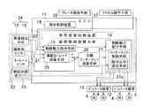
- the vehicle control apparatus 10 shown in FIG. 1A is provided with a vehicle attitude control apparatus (described later) that performs control to stabilize the vehicle attitude.
- the vehicle control device 10 includes an ECU 11 mounted on the vehicle, a plurality (two in this example) of inverter devices 12 provided for the front and rear motors 4, and sensors 13.
- the ECU 11 includes an integrated control unit 14 that performs overall control and cooperative control of the entire vehicle, a braking / driving force command unit 15, and a braking / driving force distribution unit 16.
- the braking / driving force command means 15 is realized by software or hardware from an operation amount detection signal of the accelerator operation means 17 such as an accelerator pedal and an operation amount detection signal of the brake operation means 18 such as a brake pedal.
- an operation amount detection signal of the accelerator operation means 17 such as an accelerator pedal
- an operation amount detection signal of the brake operation means 18 such as a brake pedal.
- LUT Look Up Table
- a predetermined conversion function stored in a software library (Library) or equivalent hardware, etc. hereinafter referred to as “realization model”
- the braking / driving force distribution means 16 includes a command input torque from the braking / driving force command means 15 to each of the wheels 2 and 3 (FIG. 1A), and a yaw moment control torque (described later) of each of the wheels 2 and 3 (FIG. 1A).
- a hardware circuit or processor (not shown) that can distribute and output individual command output torques to the inverter device 12 of each motor 4 according to the setting rule using the above-described implementation model. It consists of software functions.
- Each inverter device 12 is a device that converts DC power of a battery (not shown) into AC power for driving the motor 4, and has a control unit (not shown) for controlling the output, and the distribution The assigned motor 4 is controlled according to the command output torque.
- one inverter device 12 is provided for each of the two front and rear motors 4, but the front and rear inverter devices 12 are provided in the left and right motors 4, 4 in one inverter device 12.
- each inverter device 12 is provided with a power circuit section (not shown) such as a gate circuit of a switching element for converting into AC power for the left and right motors 4 and 4, respectively.
- One control unit is configured to control the left and right power circuit units by time division or the like. Instead of providing two inverter devices 12 as described above, a total of four inverter devices 12 may be provided for each motor 4.
- the ECU 11 includes a computer having a processor such as a microcomputer, a ROM (Read Only Memory) having a program executed by the processor, and various electronic circuits such as a RAM (Random Access Memory) and a coprocessor (Co-Processor). Consists of.
- the ECU 11 and each inverter device 12 are connected by an in-vehicle communication network such as a CAN (Control Area Network), for example.
- the ECU 11 is provided with a posture control device main body 19.
- the vehicle is also provided with vehicle speed detection means 20 for detecting the vehicle speed, a steering angle sensor 21 for detecting the steering angle, a yaw rate sensor 22 for detecting the yaw rate, and a longitudinal acceleration sensor 23 for detecting the longitudinal acceleration.
- the steering angle sensor 21 is a sensor that detects a steering angle of a steering means such as a steering wheel (not shown) or a sensor that detects a steering angle from a steering device that steers wheels 2 and 3 (not shown).
- the vehicle attitude control device 24 includes at least the attitude control device main body 19 and the sensors 13.
- the attitude control device main body 19 includes the braking / driving force command means 15, a standard yaw rate calculation means 25, a target yaw moment calculation means 26, and the braking / driving force distribution means 16.
- FIG. 3 is a control block diagram of the vehicle attitude control device 24.
- the reference yaw rate calculation means 25 is based on the following realization model or addition function, multiplication function, division function, and the like from the vehicle speed and steering angle ⁇ h that affect the following damping ratio? And natural frequency ⁇ n. It is composed of a hardware circuit or a software function on a processor (not shown) that can calculate and output a reference yaw rate ⁇ ref based on the following vehicle model using hardware or the like equivalent to it. Yes.
- a hardware circuit that can calculate and output the target yaw moment M t as follows using the above-described implementation model, or a hardware that is a multiplication function or an equivalent such as a coprocessor, or the like. It is composed of software functions on a processor (not shown).
- M t K P ⁇
- K P is a gain constant.
- Target yaw moment calculation unit 26 as follows, to calculate a yaw moment control torque T M of the respective wheels from the calculated target yaw moment M t.
- T M_ALL is the sum of yaw moment control torques T M (T Mi ) of all wheels, and the sign sign represents the direction of rotation.
- the braking / driving force distribution unit 16 includes a yaw moment control unit 27.
- the yaw moment control means 27 uses the above-described realization model, or an addition function or equivalent hardware such as an adder, and the like based on the accelerator depression amount and the like. 15 is added to the command input torque T * of each wheel calculated and output in step 15, and the yaw moment control torque T M necessary for realizing the target yaw moment M t calculated by the target yaw moment calculating means 26 is added.
- a hardware circuit or a software function on a processor (not shown) that can calculate and output a command output torque T (FIG. 3).
- the yaw moment control means 27 in this example is configured as a part of the braking / driving force distribution means 16, but may be provided separately from the braking / driving force distribution means 16.
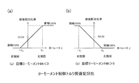
- FIG. 4 is a diagram showing the front / rear distribution ratio of the yaw moment control torque by the vehicle attitude control device.
- FIGS. 1A to 3 are also referred to as necessary. As shown in graphs (a) of FIG. 3 and FIG.
- the yaw moment control means 27 when generating a clockwise yaw moment, indicates that the target yaw moment is negative (M t ⁇ 0) and the actual yaw rate ⁇ is When the yaw rate is larger than a preset yaw rate ⁇ 1 (where ⁇ 1 > 0) ( ⁇ > ⁇ 1 ), the yaw moment control torque necessary for realizing the target yaw moment is applied only to the front wheels 3 by determining that it is an oversteer. That is, the front / rear distribution ratio (or front wheel distribution ratio ⁇ , the same applies hereinafter) of the yaw moment control torque is 100% for the front wheels and 0% for the rear wheels. As a result, the vehicle posture can be stabilized when the vehicle is turning right and oversteering.
- the yaw moment control means 27 is ( ⁇ ⁇ 2 ) when the target yaw moment is negative (M t ⁇ 0) and the actual yaw rate ⁇ is smaller than a preset yaw rate ⁇ 2 (where ⁇ 2 > 0). ),
- the yaw moment control torque necessary to realize the target yaw moment is applied only to the rear wheel 2 by determining the understeer. That is, the front / rear distribution ratio of the yaw moment control torque is 0% for the front wheels and 100% for the rear wheels. As a result, it is possible to improve the course traceability of the traveling of the vehicle when the vehicle is turning right and understeering.
- the yaw moment control means 27 sets the yaw rate ⁇ 1 to a value larger than the yaw rate ⁇ 2 (the same applies when the target yaw moment described later is positive).
- These yaw rate set values ⁇ 1 and ⁇ 2 are set based on vehicle characteristics such as the position of the center of gravity of the vehicle and cornering power.
- the distribution ratio changing means 27a (FIG. 1B) of the yaw moment control means 27 is such that the target yaw moment is negative (M t ⁇ 0) and the actual yaw rate ⁇ is - ⁇ 2 and ⁇ 1 where the sign is inverted.
- the front / rear distribution ratio of the yaw moment control torque distributed to the front and rear wheels 3 and 2 is continuously changed according to the detected actual yaw rate ⁇ .
- the yaw moment control means 27 sets the distribution ratio of the rear wheels 2 to be large during straight traveling where the actual yaw rate ⁇ is near “0”.
- the distribution ratio changing means 27a receives the actual yaw rate ⁇ using the above-described realization model, and uses the two characteristic graphs shown in FIG. A hardware circuit or a software function on a processor (not shown) that can calculate and output the distribution ratio ⁇ .
- the yaw moment control means 27 considers the case where the counterclockwise yaw moment is generated, and the yaw moment control means 27 has a positive target yaw moment (M t > 0), When the actual yaw rate ⁇ is greater than the preset yaw rate ⁇ 2 , the yaw moment control torque necessary for realizing the target yaw moment is applied only to the rear wheel 2. Thereby, when the vehicle is turning left and understeering, it is possible to improve the course trace performance.
- the yaw moment control means 27 is a yaw moment necessary for realizing the target yaw moment when the target yaw moment is positive (M t > 0) and the actual yaw rate ⁇ is smaller than a preset yaw rate ⁇ 1.
- a control torque is applied only to the front wheel 3. As a result, the vehicle posture can be stabilized when the vehicle is turning left and oversteering.
- the distribution ratio changing means 27a (FIG. 1B) of the yaw moment control means 27 is such that the target yaw moment is positive (M t > 0) and the actual yaw rate ⁇ is - ⁇ 1 and ⁇ 2 in which the sign is inverted.
- the front / rear distribution ratio of the yaw moment control torque distributed to the front and rear wheels 3, 2 is continuously changed according to the detected actual yaw rate ⁇ .
- the yaw moment control means 27 sets the distribution ratio of the rear wheels 2 to be large during straight traveling where the actual yaw rate ⁇ is near “0”.
- the yaw moment control means 27 changes the set values ⁇ 1 and ⁇ 2 of the yaw rate according to the longitudinal acceleration detected by the longitudinal acceleration sensor 23 shown in FIG. 1B. Specifically, ⁇ 1 is increased and ⁇ 2 is decreased as the forward acceleration increases. That is, the values of ⁇ 1 and ⁇ 2 are increased, the values of ⁇ 2 and ⁇ 1 are decreased, and the longitudinal distribution ratio of the braking / driving force of the rear wheel 2 is increased. Thereby, the influence of the fall of the grip force accompanying the load reduction of the front wheel 3 can be reduced, and vehicle behavior can be stabilized.
- the yaw moment control torque to be applied to a certain wheel (hereinafter referred to as “wheel A”) is different in sign from the command input torque of the wheel on the left and right sides opposite to each other (hereinafter referred to as “wheel B”)
- the yaw moment control means 27 executes the following procedure. First, the yaw moment control torque to be originally applied to the wheel A is applied to the wheel B (subtract when the yaw moment control torque is negative and the command input torque is positive). When the sum of the command input torque of the wheel B and the yaw moment control torque that should be originally applied to the wheel A does not exceed zero, the procedure ends.
- the command output torque of the wheel B is set to zero.
- the sum of the command input torque of wheel B and the yaw moment control torque to be applied to wheel A exceeding zero is added to the command input torque of wheel A to obtain the command output torque of wheel A.
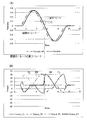
- a graph (A) in FIG. 5 is a diagram showing a reference yaw rate and an actual yaw rate when so-called sine steering is performed, and a graph (B) in FIG. 5 shows a yaw moment control torque to which this vehicle attitude control device is applied.
- FIG. This example is a simulation result when sine steering is performed in which the sign of the actual yaw rate is reversed.
- T * the command input torque
- FIG. 6 is a diagram schematically showing an example of the braking / driving force of each wheel when turning right and understeering ( ⁇ ⁇ 2 , target yaw moment M t ⁇ 0).
- a constant driving force command output torque
- the driving force yaw moment control torque
- the driving force yaw moment control torque
- a braking force having a magnitude equal to the driving force is added to the input torque.
- the driving force (yaw moment control torque) is added to the command input torque to the left rear wheel 2, and the right front wheel 3, the braking force (yaw moment control torque) having the same magnitude as the driving force is added, the command output torque of the right front wheel 3 becomes zero, and the remaining braking force (yaw moment control torque) is added to the right rear wheel 2.
- the sum of the absolute values of the command output torque is reduced, and the vehicle stability is improved.
- the distribution ratio changing means 27a of the yaw moment control means 27 allows the detected actual yaw rate ⁇ to be within a predetermined range in which the sign is reversed ( ⁇ 2 ⁇ ⁇ ⁇ ⁇ ).
- the front-rear distribution ratio of the yaw moment control torque distributed to the front and rear wheels 3, 2 is continuously changed according to the detected actual yaw rate ⁇ .
- the front / rear distribution ratio of the yaw moment control torque distributed to the front and rear wheels 3 and 2 continuously changes, so that the vehicle posture is stabilized without giving the driver a sense of incongruity.
- the response of the yaw rate can be improved by setting and adjusting the parameter of the front / rear distribution ratio according to the vehicle characteristics, the front / rear acceleration, and the like.
- the yaw moment control means 27 sets the yaw rate ⁇ 1 to a value larger than the yaw rate ⁇ 2 , the front / rear distribution ratio of the braking / driving force of the rear wheels 2 rather than the front wheels 3 is determined during straight traveling where the actual yaw rate is near “0”. Can be bigger. Thereby, it is possible to suppress an understeer tendency at the start of steering from straight traveling, and it is possible to improve the response of the yaw rate.
- the in-wheel motor drive device IWM is a so-called direct motor type in which a cycloid reducer, a planetary reducer, a two-axis parallel reducer, and other reducers can be applied. Also good.
- the vehicle may be provided with a radar or an imaging means (radar or the like) for detecting an obstacle or the like, and the braking / driving force command means 15 may generate a command input torque based on data provided from the radar or the like.
- an in-wheel motor type four-wheel drive vehicle has been described.
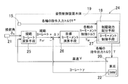
- a non-in-wheel motor type vehicle for example, as shown in FIG.
- a four-wheel drive vehicle having a mechanism for transmitting the output of the motor 4 installed on the vehicle body to each of the wheels 3 and 2 via the drive shafts 28 and the like and independently controlling the drive torque of the wheels 3 and 2.
- this control can be applied to a four-wheel drive vehicle in which a mechanism capable of arbitrarily moving the torque of the left and right wheels is mounted on the front and rear wheels.
Landscapes
- Engineering & Computer Science (AREA)
- Mechanical Engineering (AREA)
- Transportation (AREA)
- Chemical & Material Sciences (AREA)
- Combustion & Propulsion (AREA)
- Power Engineering (AREA)
- Automation & Control Theory (AREA)
- Control Of Driving Devices And Active Controlling Of Vehicle (AREA)
- Electric Propulsion And Braking For Vehicles (AREA)
- Regulating Braking Force (AREA)
- Tires In General (AREA)
- Arrangement And Mounting Of Devices That Control Transmission Of Motive Force (AREA)
Abstract
各輪に制駆動力をそれぞれ個別に与える四輪駆動車両において、運転者に違和感を与えることなく車両姿勢の安定化を図ることができる車両姿勢制御装置を提供する。この車両姿勢制御装置(24)は、四輪駆動車両を制御する車両制御装置(10)に設けられ、規範ヨーレート演算手段(25)と、ヨーレートセンサ(22)と、目標ヨーモーメント演算手段(26)と、制駆動力指令手段(15)と、ヨーモーメント制御手段(27)とを備える。ヨーモーメント制御手段(27)は、ヨーレートセンサ(22)で検出される実ヨーレートにつき、この実ヨーレートが、符号の正負が反転する定められた範囲内のとき、前記検出される実ヨーレートに応じて前後輪(3), (2)に配分するヨーモーメント制御トルクの前後配分比率を連続的に変化させる配分比率変化手段(27a)を有する。
Description
本出願は、2015年4月14日出願の特願2015-82309の優先権を主張するものであり、その全体を参照により本願の一部をなすものとして引用する。
この発明は、四輪駆動車両において、左右の前輪および左右の後輪に加える制駆動力を適切に配分して車両姿勢の安定化を図る車両姿勢制御装置に関する。
従来の車両姿勢制御装置では、例えば、車速や操舵角等の各種の車両の状態量から目標ヨーレートを求め、目標ヨーレートと実ヨーレートとの偏差に基づいて目標ヨーモーメントを生成し、その目標ヨーモーメントを実現するために必要な制駆動力を左右の各輪に加える。これにより、安定した車両挙動を確保するものが知られている(特許文献1)。
また、四輪駆動車において、目標ヨーレートと実ヨーレートとの偏差に基づいて制御され、実ヨーレートが目標ヨーレートに一致もしくは近似するよう前後輪への駆動力配分率を変えるものが公知である。例えば、実ヨーレートが目標ヨーレートより大きいときには前輪側のトルク配分を大きくし、実ヨーレートが目標ヨーレートより小さいときには後輪側のトルク配分を大きくする技術が示されている(特許文献2)。
四輪独立駆動車のような四輪個別に前後力を制御可能な車両、もしくは四輪全てに駆動力配分が可能な車両において、前記特許文献1に記載の技術のような目標ヨーレートと実ヨーレートとの偏差に基づく目標ヨーモーメントを実現するための前後力を、前記特許文献2に記載の技術のように、目標ヨーレートと実ヨーレートとの偏差に基づいて前後輪へ分配すると、実ヨーレートの符号が反転するときに前輪と後輪の駆動力配分が切り替わる。このため、前後輪のトルクが不連続に変化し、運転者に違和感を与える恐れがある。
この発明の目的は、各輪に制駆動力をそれぞれ個別に与える四輪駆動車両において、運転者に違和感を与えることなく車両姿勢の安定化を図ることができる車両姿勢制御装置を提供することである。
以下、この発明について、理解を容易にするために、便宜上実施形態の符号を参照して説明する。
この発明の車両姿勢制御装置24は、左右の前輪3,3および左右の後輪2,2の各輪に制駆動力をそれぞれ個別に与える制駆動力発生手段4を備えた四輪駆動車両を制御する車両制御装置10に設けられる車両姿勢制御装置であって、
車速と操舵角から規範ヨーレートを求める規範ヨーレート演算手段25と、
前記車両の実ヨーレートを検出するヨーレートセンサ22と、
前記規範ヨーレート演算手段25で求められた規範ヨーレートと、前記ヨーレートセンサ22によって検出された実ヨーレートとのヨーレート偏差に基づいて目標ヨーモーメントを演算する目標ヨーモーメント演算手段26と、
制駆動力の操作手段17,18が出力する操作量を基本として各輪3,2に配分する制駆動力の指令入力トルクを生成する制駆動力指令手段15と、
この制駆動力指令手段15で生成する制駆動力の指令入力トルクに、前記目標ヨーモーメント演算手段26により演算された目標ヨーモーメントを実現するために必要なヨーモーメント制御トルクを加えるヨーモーメント制御手段27と、
を備え、
前記ヨーモーメント制御手段27は、前記ヨーレートセンサ22で検出される実ヨーレートにつき、この実ヨーレートが、符号の正負が反転する定められた範囲内のとき、前記検出される実ヨーレートに応じて前後輪3,2に配分するヨーモーメント制御トルクの前後配分比率を連続的に変化させる配分比率変化手段27aを有する。
前記定められた範囲は、例えば、試験やシミュレーション等の結果により定められる。
この構成によると、目標ヨーモーメント演算手段26は、求められた規範ヨーレートと検出された実ヨーレートとのヨーレート偏差Δγに基づいて目標ヨーモーメントMtを演算する。ヨーモーメント制御手段27は、制駆動力指令手段15で生成する制駆動力の指令入力トルクに、演算された目標ヨーモーメントMtを実現するために必要なヨーモーメント制御トルクを加える。
ヨーモーメント制御手段27の配分比率変化手段27aは、検出される実ヨーレートγが、符号の正負が反転する定められた範囲内(-γ2≦γ≦γ1)のとき、前記検出される実ヨーレートγに応じて前後輪3,2に配分するヨーモーメント制御トルクの前後配分比率を連続的に変化させる。このように実ヨーレートγの符号が反転するとき、前後輪3,2に配分するヨーモーメント制御トルクの前後配分比率が連続的に変化するため、運転者に違和感を与えることなく、車両姿勢を安定化させることができる。さらに、車両特性や前後加速度等に応じて前後配分比率のパラメータを設定、調節することで、ヨーレートの応答を向上させることができる。なお前記「連続的に」とは、直線的な変化だけでなく、前後配分比率が微分可能に変化するような二次曲線等も含む。
前記ヨーモーメント制御手段27は、
前記目標ヨーモーメントが負のとき、且つ、前記実ヨーレートが設定されたヨーレートγ1(ただしγ1>0)より大きいとき、前記制駆動力指令手段15からの指令入力トルクに対して、目標ヨーモーメントを実現するために必要なヨーモーメント制御トルクを前輪3のみに加え、
前記目標ヨーモーメントが負のとき、且つ、前記実ヨーレートが前記ヨーレートγ1とは別に設定されたヨーレート-γ2(ただしγ2>0)より小さいとき、前記制駆動力指令手段15からの指令入力トルクに対して、目標ヨーモーメントを実現するために必要なヨーモーメント制御トルクを後輪2のみに加えるものとしても良い。
前記目標ヨーモーメントが負のとき、且つ、前記実ヨーレートが設定されたヨーレートγ1(ただしγ1>0)より大きいとき、前記制駆動力指令手段15からの指令入力トルクに対して、目標ヨーモーメントを実現するために必要なヨーモーメント制御トルクを前輪3のみに加え、
前記目標ヨーモーメントが負のとき、且つ、前記実ヨーレートが前記ヨーレートγ1とは別に設定されたヨーレート-γ2(ただしγ2>0)より小さいとき、前記制駆動力指令手段15からの指令入力トルクに対して、目標ヨーモーメントを実現するために必要なヨーモーメント制御トルクを後輪2のみに加えるものとしても良い。
ヨーモーメント制御手段27は、右回りのヨーモーメントを発生させる場合に、目標ヨーモーメントが負で(Mt<0)、実ヨーレートがヨーレートγ1(ただしγ1>0)より大きいとき、オーバーステアと判断して指令入力トルクに対してヨーモーメント制御トルクを前輪3のみに加える。これにより、車両が右旋回でオーバーステアのときに車両姿勢の安定化を図ることができる。ヨーモーメント制御手段27は、右回りのヨーモーメントを発生させる場合に、実ヨーレートがヨーレート-γ2(ただしγ2>0)より小さいとき、アンダーステアと判断して指令入力トルクに対してヨーモーメント制御トルクを後輪2のみに加える。これにより、車両が右旋回でアンダーステアのときに車両姿勢の安定化を図ることができる。
前記ヨーモーメント制御手段27は、
前記目標ヨーモーメントが正のとき、且つ、前記実ヨーレートが設定されたヨーレートγ2(ただしγ2>0)より大きいとき、前記制駆動力指令手段15からの指令入力トルクに対して、目標ヨーモーメントを実現するために必要なヨーモーメント制御トルクを後輪2のみに加え、
前記目標ヨーモーメントが正のとき、且つ、前記実ヨーレートが前記ヨーレートγ2とは別に設定されたヨーレート-γ1(ただしγ1>0)より小さいとき、前記制駆動力指令手段15からの指令入力トルクに対して、目標ヨーモーメントを実現するために必要なヨーモーメント制御トルクを前輪3のみに加えるものとしても良い。
前記目標ヨーモーメントが正のとき、且つ、前記実ヨーレートが設定されたヨーレートγ2(ただしγ2>0)より大きいとき、前記制駆動力指令手段15からの指令入力トルクに対して、目標ヨーモーメントを実現するために必要なヨーモーメント制御トルクを後輪2のみに加え、
前記目標ヨーモーメントが正のとき、且つ、前記実ヨーレートが前記ヨーレートγ2とは別に設定されたヨーレート-γ1(ただしγ1>0)より小さいとき、前記制駆動力指令手段15からの指令入力トルクに対して、目標ヨーモーメントを実現するために必要なヨーモーメント制御トルクを前輪3のみに加えるものとしても良い。
ヨーモーメント制御手段27は、左回りのヨーモーメントを発生させる場合に、目標ヨーモーメントが正で(Mt>0)、実ヨーレートがヨーレートγ2(ただしγ2>0)より大きいとき、アンダーステアと判断して指令入力トルクに対してヨーモーメント制御トルクを後輪2のみに加える。これにより、車両が左旋回でアンダーステアのときに車両姿勢の安定化を図ることができる。ヨーモーメント制御手段27は、左回りのヨーモーメントを発生させる場合に、実ヨーレートがヨーレート-γ1(ただしγ1>0)より小さいとき、オーバーステアと判断して指令入力トルクに対してヨーモーメント制御トルクを前輪3のみに加える。これにより、車両が左旋回でオーバーステアのときに車両姿勢の安定化を図ることができる。
前記ヨーモーメント制御手段27は、前記ヨーレートγ1を前記ヨーレートγ2より大きい値に設定しても良い。ヨーレートの設定値γ1,γ2は、車両の重心位置、コーナリングパワー等の車両特性に基づいてそれぞれ設定する。この場合、実ヨーレートが「0」近傍となる直進走行時に、前輪3よりも後輪2の制駆動力の前後配分比率を大きくすることができる。これにより、直進走行から操舵開始時のアンダーステア傾向を抑制でき、ヨーレートの応答を向上させることができる。
前記車両の前後加速度を検出する前後加速度センサ23を設け、前記ヨーモーメント制御手段27は、前記前後加速度センサ23で検出された前後加速度が大きい程、前記ヨーレートγ1を上昇させ、前記ヨーレートγ2を低下させても良い。この場合、車両が前進しようとする加速度が大きい程、γ1を上昇させ、γ2を低下させる。すなわちγ1,-γ2は上昇、γ2,-γ1は低下させ、後輪2の制駆動力の前後配分比率を大きくする。これにより、前輪3の荷重減少に伴うグリップ力の低下の影響を低減することができ、車両挙動を安定化することができる。
前記ヨーモーメント制御手段27は、
対象とする輪における、前記目標ヨーモーメントを実現するために必要なヨーモーメント制御トルクが、前記対象とする輪と左右同側で前後反対側の反対輪に対する前記制駆動力指令手段15からの指令入力トルクと符号が異なる場合には、前記反対輪に、前記目標ヨーモーメントを実現するために必要なヨーモーメント制御トルクを加え、
前記制駆動力指令手段15からの指令入力トルクと前記目標ヨーモーメントを実現するために必要なヨーモーメント制御トルクとの和が零を超えないとき、その値を、前記反対輪に配分する制駆動力(指令出力トルク)とし、
前記制駆動力指令手段15からの指令入力トルクと前記目標ヨーモーメントを実現するために必要なヨーモーメント制御トルクとの和が零を超えるとき、前記反対輪に配分する制駆動力(指令出力トルク)を零とし、超えた分を前記対象とする輪に加えるものとしても良い。
この構成によると、ヨーモーメント制御トルクを印加する輪と前後反対側の輪のトルクの絶対値の大きさを低下させることができる。これにより、アンダーステアやオーバーステアの車両特性をそれぞれ低減できる。
請求の範囲および/または明細書および/または図面に開示された少なくとも2つの構成のどのような組合せも、この発明に含まれる。特に、請求の範囲の各請求項の2つ以上のどのような組合せも、この発明に含まれる。
この発明は、添付の図面を参考にした以下の好適な実施形態の説明から、より明瞭に理解されるであろう。しかしながら、実施形態および図面は単なる図示および説明のためのものであり、この発明の範囲を定めるために利用されるべきものではない。この発明の範囲は添付の請求の範囲によって定まる。添付図面において、複数の図面における同一の符号は、同一または相当する部分を示す。
この発明の実施形態に係る車両姿勢制御装置を図1Aないし図6と共に説明する。なお以下の説明は車両姿勢制御方法についての説明も含む。図1Aは、この実施形態に係る車両姿勢制御装置のシステム構成を平面視で概略示す図である。この車両姿勢制御装置を搭載した左右輪独立駆動式車両である電気自動車1は、車両の左右の後輪となる車輪2および左右の前輪となる車輪3が、いずれも動力源となる電動のモータ4で独立して駆動される四輪独立駆動の自動車(四輪駆動車両)である。前輪となる車輪3は操舵輪とされている。各モータ4は、それぞれ駆動力および制動力を発生可能な制駆動力発生手段である。駆動力および制動力を総称して「制駆動力」と言う。
各モータ4は、本実施形態では、例えばインホイールモータ駆動装置IWMを構成する。図2に示すように、インホイールモータ駆動装置IWMは、モータ4、減速機6、および車輪用軸受7を有し、これらの一部または全体が車輪2,(3)内に配置される。モータ4の回転は、減速機6および車輪用軸受7を介して車輪2,(3)に伝達される。車輪用軸受7のハブ輪7aのフランジ部には摩擦ブレーキ装置8を構成するブレーキロータ8aが固定され、同ブレーキロータ8aは車輪2,(3)と一体に回転する。モータ4は、例えば、ロータ4aのコア部に永久磁石が内蔵された埋込磁石型同期モータである。このモータ4は、ハウジング4cに固定したステータ4bと、回転出力軸9に取り付けた上記のロータ4aとの間にラジアルギャップを設けたモータである。
図1Aおよび図1Bを用いて制御系を説明する。図1Aに示す車両制御装置10には、車両姿勢を安定化する制御を行う車両姿勢制御装置(後述する)が設けられる。車両制御装置10は、車両に搭載されたECU11と、前後のモータ4に対して設けられた複数(この例では二つ)のインバータ装置12と、センサ類13とを有する。
図1Bに示すように、ECU11は、自動車全般の統括制御や協調制御を行う統合制御手段14と、制駆動力指令手段15と、制駆動力配分手段16とを有する。制駆動力指令手段15は、アクセルペダル等のアクセル操作手段17の操作量の検出信号と、ブレーキペダル等のブレーキ操作手段18の操作量の検出信号とから、ソフトウエアやハードウエアで実現されたLUT(Look Up Table)、またはソフトウエアのライブラリ(Library)に収められた所定の変換関数やそれに等価のハードウエア等(以下、「具現化モデル」という。)を用いて、車両全体の制駆動力の指令入力トルクを生成する手段である。制駆動力配分手段16は、制駆動力指令手段15から各輪2,3(図1A)への指令入力トルクと、各輪2,3(図1A)のヨーモーメント制御トルク(後述する)とから、具体的には、上記の具現化モデルを用いて、設定規則に従い、各モータ4のインバータ装置12へ個別の指令出力トルクを分配して出力しうるハードウエア回路またはプロセッサ(不図示)上のソフトウエア関数で構成されている。
各インバータ装置12は、図示外のバッテリの直流電力をモータ4の駆動のための交流電力に変換する装置であって、その出力を制御する制御部(図示せず)を有し、前記の分配された指令出力トルクに従って担当のモータ4を制御する。インバータ装置12は、図示の例では、前後それぞれ二台のモータ4に対して一台ずつ設けているが、前後の各インバータ装置12は、一台のインバータ装置12内に左右のモータ4,4を個別に制御する構成を有している。例えば、各インバータ装置12は、交流電力に変換するスイッチング素子のゲート回路等のパワー回路部(図示せず)が左右のモータ4,4に対してそれぞれ別に設けられ、それらのパワー回路部の前記制御部は一台で、時分割等により左右のパワー回路部を制御する構成とされる。前記インバータ装置12は、前記のように二台設ける代わりに、各モータ4毎に個別に設け合計四台としても良い。
ECU11は、マイクロコンピュータ等のプロセッサを有するコンピュータと前記プロセッサで実行されるプログラムを有するROM(Read Only Memory)、並びにRAM(Random Access Memory)やコプロセッサ(Co-Processor)等の各種の電子回路等で構成される。ECU11と各インバータ装置12とは、例えば、CAN(コントロール・エリア・ネットワーク)等の車内通信網で接続されている。ECU11には、姿勢制御装置本体19が設けられている。また車両には、センサ類13として、車速を検出する車速検出手段20、操舵角を検出する操舵角センサ21、ヨーレートを検出するヨーレートセンサ22、および前後加速度を検出する前後加速度センサ23が設けられている。操舵角センサ21は、図示外のステアリングホイール等の操舵手段の操舵角を検出するセンサ、または図示外の車輪2、3を転舵させる転舵装置から操舵角を検出するセンサである。
車両姿勢制御装置24は、少なくとも姿勢制御装置本体19と前記センサ類13とから構成される。姿勢制御装置本体19は、前記制駆動力指令手段15と、規範ヨーレート演算手段25と、目標ヨーモーメント演算手段26と、前記制駆動力配分手段16とを有する。
図3は、この車両姿勢制御装置24の制御ブロック図である。規範ヨーレート演算手段25は、下記減衰比?や固有振動数ωnに影響する車速と操舵角γhとから、具体的には、上記の具現化モデル、または加算関数、乗算関数および除算関数やそれに等価の例えばコプロセッサであるハードウエア等を用いて、以下の車両モデルに基づき規範ヨーレートγrefを算出して出力しうるハードウエア回路またはプロセッサ(不図示)上のソフトウエア関数で構成されている。

目標ヨーモーメント演算手段26は、規範ヨーレート演算手段25で求められた規範ヨーレートγrefと、ヨーレートセンサ22によって検出された実ヨーレートγとのヨーレート偏差Δγ(Δγ=γref-γ)に基づいて、具体的には、上記の具現化モデル、または乗算関数やそれに等価の例えばコプロセッサであるハードウエア等を用いて、以下のように目標ヨーモーメントMtを演算して出力しうるハードウエア回路またはプロセッサ(不図示)上のソフトウエア関数で構成されている。
Mt=KPΔγ
ここでKPはゲイン定数である。
Mt=KPΔγ
ここでKPはゲイン定数である。
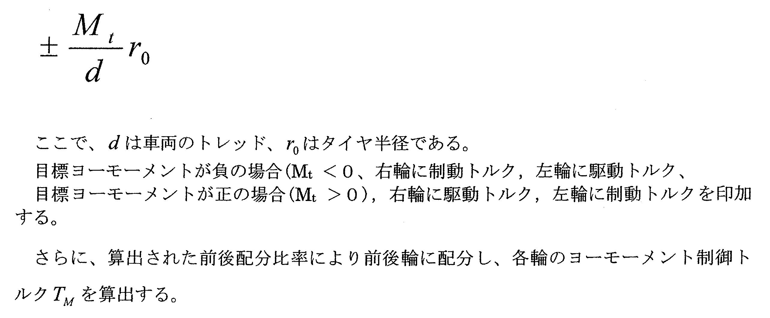
目標ヨーモーメント演算手段26は、以下のように、前記演算された目標ヨーモーメントMtから各輪のヨーモーメント制御トルクTMを算出する。先ず、目標ヨーモーメントMtから、車両全体のヨーモーメント制御トルクの大きさTM_ALLを次式により算出する。なお、TM_ALLは全車輪のヨーモーメント制御トルクTM(TMi)の和であり、符号の正負は回転の向きを表す。ここで、各輪のヨーモーメント制御トルクTMiは(i=1,…,4)、後述の前後配分比率から定まる前輪配分比α(0≦α≦1で、前後配分比率が100:0のときは1となり、前後配分比率が50:50のときは0.5となる)を用いると、以下の様にあらわされる。
・各前輪3については、TM1 = TM2 = TM_ALL × α /2
・各後輪2については、TM3 = TM4 = TM_ALL ×(1-α)/2
・各前輪3については、TM1 = TM2 = TM_ALL × α /2
・各後輪2については、TM3 = TM4 = TM_ALL ×(1-α)/2
制駆動力配分手段16はヨーモーメント制御手段27を含む。このヨーモーメント制御手段27は、具体的には、上記の具現化モデル、または加算関数やそれに等価の例えば加算器であるハードウエア等を用いて、アクセル踏込量等に基づいて制駆動力指令手段15で計算されて出力される各輪の指令入力トルクT*に、目標ヨーモーメント演算手段26により演算された目標ヨーモーメントMtを実現するために必要なヨーモーメント制御トルクTMを加えて、指令出力トルクT(図3)を算出して出力しうるハードウエア回路またはプロセッサ(不図示)上のソフトウエア関数で構成されている。
Ti=Ti *+TMi(i=1,…,4)
なお、上式は各車輪毎に表された式であり、iは4つの車輪を識別する数字である(例えば、i=1,…,4は、各々、左前輪、右前輪、左後輪、右後輪を表す)。また、この例のヨーモーメント制御手段27は、制駆動力配分手段16の一部として構成されているが、制駆動力配分手段16とは別に設けられていても良い。
Ti=Ti *+TMi(i=1,…,4)
なお、上式は各車輪毎に表された式であり、iは4つの車輪を識別する数字である(例えば、i=1,…,4は、各々、左前輪、右前輪、左後輪、右後輪を表す)。また、この例のヨーモーメント制御手段27は、制駆動力配分手段16の一部として構成されているが、制駆動力配分手段16とは別に設けられていても良い。
図4は、この車両姿勢制御装置によるヨーモーメント制御トルクの前後配分比率を示す図である。以後、図1A乃至図3も必要に応じて適宜参照する。図3および図4のグラフ(a)に示すように、右回りのヨーモーメントを発生させる場合に、ヨーモーメント制御手段27は、目標ヨーモーメントが負で(Mt<0)、実ヨーレートγが予め設定されたヨーレートγ1(ただしγ1>0)より大きいとき(γ>γ1)、オーバーステアと判断し目標ヨーモーメントを実現するために必要なヨーモーメント制御トルクを前輪3のみに加える。つまりヨーモーメント制御トルクの前後配分比率(または前輪配分比α。以下同じ。)を、前輪100%、後輪0%とする。これにより車両が右旋回でオーバーステアのときに車両姿勢の安定化を図ることができる。
ヨーモーメント制御手段27は、目標ヨーモーメントが負(Mt<0)で、且つ、実ヨーレートγが予め設定されたヨーレート-γ2(ただしγ2>0)より小さいとき(γ<-γ2)、アンダーステアと判断し目標ヨーモーメントを実現するために必要なヨーモーメント制御トルクを後輪2のみに加える。つまりヨーモーメント制御トルクの前後配分比率を、前輪0%、後輪100%とする。これにより車両が右旋回でアンダーステアのときに車両の進行のコーストレース性の向上を図ることができる。またヨーモーメント制御手段27は、ヨーレートγ1をヨーレートγ2より大きい値に設定している(後述の目標ヨーモーメントが正のときも同じ)。これらヨーレートの設定値γ1とγ2は、車両の重心位置、コーナリングパワー等の車両特性に基づいて設定する。
ヨーモーメント制御手段27の配分比率変化手段27a(図1B)は、目標ヨーモーメントが負(Mt<0)で、且つ、実ヨーレートγが、符号の正負が反転する-γ2とγ1の範囲内のとき(-γ2≦γ≦γ1)、検出される実ヨーレートγに応じて前後輪3,2に配分するヨーモーメント制御トルクの前後配分比率を連続的に変化させる。この場合に、ヨーモーメント制御手段27は、実ヨーレートγが「0」近傍となる直進走行時に後輪2の配分比率を大きく設定している。なお、配分比率変化手段27aは、具体的には、上記の具現化モデルを用いて、実ヨーレートγの入力を受けて、図4に示す2つの特性グラフを使用して、前後配分比率または前輪配分比αを演算して出力しうるハードウエア回路またはプロセッサ(不図示)上のソフトウエア関数で構成されている。
図3および図4のグラフ(b)に示すように、左回りのヨーモーメントを発生させる場合も同様に考えて、ヨーモーメント制御手段27は、目標ヨーモーメントが正で(Mt>0)、実ヨーレートγが予め設定されたヨーレートγ2より大きいとき、目標ヨーモーメントを実現するために必要なヨーモーメント制御トルクを後輪2のみに加える。これにより車両が左旋回でアンダーステアのときにコーストレース性の向上を図ることができる。
ヨーモーメント制御手段27は、目標ヨーモーメントが正(Mt>0)で、且つ、実ヨーレートγが予め設定されたヨーレート-γ1より小さいとき、目標ヨーモーメントを実現するために必要なヨーモーメント制御トルクを前輪3のみに加える。これにより車両が左旋回でオーバーステアのときに車両姿勢の安定化を図ることができる。
ヨーモーメント制御手段27の配分比率変化手段27a(図1B)は、目標ヨーモーメントが正(Mt>0)で、且つ、実ヨーレートγが、符号の正負が反転する-γ1とγ2の範囲内のとき(-γ1≦γ≦γ2)、検出される実ヨーレートγに応じて前後輪3,2に配分するヨーモーメント制御トルクの前後配分比率を連続的に変化させる。この場合に、ヨーモーメント制御手段27は、実ヨーレートγが「0」近傍となる直進走行時に後輪2の配分比率を大きく設定している。
ヨーモーメント制御手段27は、図1Bに示す前後加速度センサ23で検出された前後加速度に応じてヨーレートの設定値γ1とγ2を変化させる。具体的には、前進加速度が大きい程、γ1を上昇させ、γ2を低下させる。すなわちγ1,-γ2の値は上昇させ、γ2,-γ1の値は低下させ、後輪2の制駆動力の前後配分比率を大きくする。これにより、前輪3の荷重減少に伴うグリップ力の低下の影響を低減することができ、車両挙動を安定化し得る。
ここで、ある輪(以降、「輪A」)に印加すべきヨーモーメント制御トルクが、左右同側で前後反対側の輪(以降、「輪B」)の指令入力トルクと符号が異なる場合は、ヨーモーメント制御手段27は次の手順を実行する。先ず、輪Aに本来印加すべきヨーモーメント制御トルクを、輪Bに印加する(ヨーモーメント制御トルクが負で指令入力トルクが正の場合は減算する)。輪Bの指令入力トルクと輪Aに本来印加すべきヨーモーメント制御トルクの和が零を超えない場合は手順を終了する。
一方、輪Bの指令入力トルクと輪Aに本来印加すべきヨーモーメント制御トルクの和が零を超える場合は、輪Bの指令出力トルクは零とする。次に、輪Bの指令入力トルクと輪Aに本来印加すべきヨーモーメント制御トルクの和が零を超えた分を、輪Aの指令入力トルクに加算し、輪Aの指令出力トルクとする。この手順を全ての輪に実行する。これにより、ヨーモーメント制御トルクを印加する輪(対象とする輪A)と前後反対側の輪(反対輪B)のトルクの絶対値の大きさを低下させることができ、アンダーステアやオーバーステアの車両特性をそれぞれ低減し得る。
図5のグラフ(A)は所謂サイン操舵を行った場合の規範ヨーレートと実ヨーレートとを示す図であり、図5のグラフ(B)はこの車両姿勢制御装置を適用したヨーモーメント制御トルクを示す図である。この例は、実ヨーレートの符号の正負が反転するサイン操舵を行った場合のシミュレーション結果である。なお、このシミュレーションでは、四輪に指令入力トルクT*として一定の駆動トルク値として10を入力し、γ1=γ2としている。図5のグラフ(B)において、「FL」は左前輪のヨーモーメント制御トルク、「FR」は右前輪ヨーモーメント制御トルク、「RR」は右後輪のヨーモーメント制御トルク、「RL」は左後輪のヨーモーメント制御トルクを示す(図8のグラフ(B)についても同じ)。
本実施の車両姿勢制御装置を適用しない従来例では、図8のグラフ(A)に示すように、実ヨーレートの符号が反転するとき(矢符t1)に、図8のグラフ(B)に示すように、ヨーモーメント制御トルクが急峻に変化する。この場合、前後輪のトルクが不連続に変化し、運転者に違和感を与える恐れがある。一方、本実施例では、図5のグラフ(A)に示すように、実ヨーレートの符号が反転するとき(矢符t1)に、図5のグラフ(B)に示すように、ヨーモーメント制御トルクを連続的に変化させることができる。
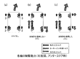
図6は、右旋回でアンダーステア時(γ<-γ2,目標ヨーモーメントMt<0)の各輪の制駆動力の例を概略示す図である。図6の説明図(a)のヨーモーメント制御(DYC)なしでは、四輪に一定の駆動力(指令出力トルク)が作用している。図6の説明図(b)の従来例のヨーモーメント制御(DYC)では、左後輪2に、指令入力トルクに対し駆動力(ヨーモーメント制御トルク)が加算され、右後輪2に、指令入力トルクに対し駆動力と等しい大きさの制動力(ヨーモーメント制御トルク)が加算される。
図6の説明図(c)の本実施形態の車両姿勢制御装置を適用したヨーモーメント制御では、左後輪2に、指令入力トルクに対し駆動力(ヨーモーメント制御トルク)が加算され、右前輪3に、駆動力と等しい大きさの制動力(ヨーモーメント制御トルク)が加算されて右前輪3の指令出力トルクは零となり、残りの制動力(ヨーモーメント制御トルク)が右後輪2に加算される。この場合、従来例のヨーモーメント制御と比較して、指令出力トルクの絶対値の合計が減少し、車両安定性が向上する。
以上説明した車両姿勢制御装置によると、ヨーモーメント制御手段27の配分比率変化手段27aは、検出される実ヨーレートγが、符号の正負が反転する定められた範囲内(-γ2≦γ≦γ1)のとき、前記検出される実ヨーレートγに応じて前後輪3,2に配分するヨーモーメント制御トルクの前後配分比率を連続的に変化させる。このように実ヨーレートの符号が反転するとき、前後輪3,2に配分するヨーモーメント制御トルクの前後配分比率が連続的に変化するため、運転者に違和感を与えることなく、車両姿勢を安定化させることができる。さらに、車両特性や前後加速度等に応じて前後配分比率のパラメータを設定、調節することで、ヨーレートの応答を向上させることができる。
ヨーモーメント制御手段27は、ヨーレートγ1をヨーレートγ2より大きい値に設定したため、実ヨーレートが「0」近傍となる直進走行時に、前輪3よりも後輪2の制駆動力の前後配分比率を大きくすることができる。これにより、直進走行から操舵開始時のアンダーステア傾向を抑制でき、ヨーレートの応答を向上させることができる。
他の実施形態について説明する。インホイールモータ駆動装置IWMにおいては、サイクロイド式の減速機、遊星減速機、2軸並行減速機、その他の減速機を適用可能であり、また、減速機を採用しない、所謂ダイレクトモータタイプであってもよい。車両に障害物等を検出するレーダーまたは撮像手段(レーダー等)を設け、制駆動力指令手段15は、前記レーダー等から与えられるデータに基づいて、指令入力トルクを生成しても良い。
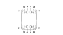
前述の実施形態では、インホイールモータ方式の四輪駆動車を用いて説明したが、非インホイールモータ方式の車両、例えば、図7に示すように、各輪3,2のそれぞれに対応させて車体に設置されたモータ4の出力を、各々のドライブシャフト28等を介して各輪3,2にそれぞれ伝達し、各輪3,2の駆動トルクを独立して制御する機構の四輪駆動車や、左右輪のトルクを任意に移動できる機構を前後輪に搭載した四輪駆動車でも本制御の適用が可能である。
以上、図面を参照しながら実施形態に基づいてこの発明を実施するための好適な形態を説明したが、今回開示された実施の形態はすべての点で例示であって制限的なものではない。この発明の範囲は上記した説明ではなくて請求の範囲によって示される。当業者であれば、本件明細書を見て、自明な範囲内で種々の変更および修正を容易に想定するであろう。したがって、そのような変更および修正は、請求の範囲から定まる発明の範囲内またはこれと均等の範囲内のものと解釈される。
2,3…車輪
4…モータ(制駆動力発生手段)
10…車両制御装置
15…制駆動力指令手段
17…アクセル操作手段
18…ブレーキ操作手段
22…ヨーレートセンサ
24…車両姿勢制御装置
25…規範ヨーレート演算手段
26…目標ヨーモーメント演算手段
27…ヨーモーメント制御手段
27a…配分比率変化手段
4…モータ(制駆動力発生手段)
10…車両制御装置
15…制駆動力指令手段
17…アクセル操作手段
18…ブレーキ操作手段
22…ヨーレートセンサ
24…車両姿勢制御装置
25…規範ヨーレート演算手段
26…目標ヨーモーメント演算手段
27…ヨーモーメント制御手段
27a…配分比率変化手段
Claims (6)
- 左右の前輪および左右の後輪の各輪に制駆動力をそれぞれ個別に与える制駆動力発生手段を備えた四輪駆動車両を制御する車両制御装置に設けられる車両姿勢制御装置であって、
車速と操舵角から規範ヨーレートを求める規範ヨーレート演算手段と、
前記車両の実ヨーレートを検出するヨーレートセンサと、
前記規範ヨーレート演算手段で求められた規範ヨーレートと、前記ヨーレートセンサによって検出された実ヨーレートとのヨーレート偏差に基づいて目標ヨーモーメントを演算する目標ヨーモーメント演算手段と、
制駆動力の操作手段が出力する操作量を基本として各輪に配分する制駆動力の指令入力トルクを生成する制駆動力指令手段と、
この制駆動力指令手段で生成する制駆動力の指令入力トルクに、前記目標ヨーモーメント演算手段により演算された目標ヨーモーメントを実現するために必要なヨーモーメント制御トルクを加えるヨーモーメント制御手段と、
を備え、
前記ヨーモーメント制御手段は、前記ヨーレートセンサで検出される実ヨーレートにつき、この実ヨーレートが、符号の正負が反転する定められた範囲内のとき、前記検出される実ヨーレートに応じて前後輪に配分するヨーモーメント制御トルクの前後配分比率を連続的に変化させる配分比率変化手段を有する車両姿勢制御装置。 - 請求項1に記載の車両姿勢制御装置において、前記ヨーモーメント制御手段は、
前記目標ヨーモーメントが負のとき、且つ、前記実ヨーレートが設定されたヨーレートγ1(ただしγ1>0)より大きいとき、前記制駆動力指令手段からの指令入力トルクに対して、目標ヨーモーメントを実現するために必要なヨーモーメント制御トルクを前輪のみに加え、
前記目標ヨーモーメントが負のとき、且つ、前記実ヨーレートが前記ヨーレートγ1とは別に設定されたヨーレート-γ2(ただしγ2>0)より小さいとき、前記制駆動力指令手段からの指令入力トルクに対して、目標ヨーモーメントを実現するために必要なヨーモーメント制御トルクを後輪のみに加える車両姿勢制御装置。 - 請求項1または請求項2に記載の車両姿勢制御装置において、前記ヨーモーメント制御手段は、
前記目標ヨーモーメントが正のとき、且つ、前記実ヨーレートが設定されたヨーレートγ2(ただしγ2>0)より大きいとき、前記制駆動力指令手段からの指令入力トルクに対して、目標ヨーモーメントを実現するために必要なヨーモーメント制御トルクを後輪のみに加え、
前記目標ヨーモーメントが正のとき、且つ、前記実ヨーレートが前記ヨーレートγ2とは別に設定されたヨーレート-γ1(ただしγ1>0)より小さいとき、前記制駆動力指令手段からの指令入力トルクに対して、目標ヨーモーメントを実現するために必要なヨーモーメント制御トルクを前輪のみに加える車両姿勢制御装置。 - 請求項2または請求項3に記載の車両姿勢制御装置において、前記ヨーモーメント制御手段は、前記ヨーレートγ1を前記ヨーレートγ2より大きい値に設定した車両姿勢制御装置。
- 請求項2ないし請求項4のいずれか1項に記載の車両姿勢制御装置において、前記車両の前後加速度を検出する前後加速度センサを設け、前記ヨーモーメント制御手段は、前記前後加速度センサで検出された前後加速度が大きい程、前記ヨーレートγ1を上昇させ、前記ヨーレートγ2を低下させる車両姿勢制御装置。
- 請求項1に記載の車両姿勢制御装置において、前記ヨーモーメント制御手段は、
対象とする輪における、前記目標ヨーモーメントを実現するために必要なヨーモーメント制御トルクが、前記対象とする輪と左右同側で前後反対側の反対輪に対する前記制駆動力指令手段からの指令入力トルクと符号が異なる場合には、前記反対輪に、前記目標ヨーモーメントを実現するために必要なヨーモーメント制御トルクを加え、
前記制駆動力指令手段からの指令入力トルクと前記目標ヨーモーメントを実現するために必要なヨーモーメント制御トルクとの和が零を超えないとき、その値を、前記反対輪に配分する制駆動力とし、
前記制駆動力指令手段からの指令入力トルクと前記目標ヨーモーメントを実現するために必要なヨーモーメント制御トルクとの和が零を超えるとき、前記反対輪に配分する制駆動力を零とし、超えた分を前記対象とする輪に加える車両姿勢制御装置。
Priority Applications (3)
| Application Number | Priority Date | Filing Date | Title |
|---|---|---|---|
| EP16779953.5A EP3284629B1 (en) | 2015-04-14 | 2016-04-05 | Vehicle orientation control device |
| US15/566,466 US10974706B2 (en) | 2015-04-14 | 2016-04-05 | Vehicle orientation control device |
| CN201680033844.3A CN107709085B (zh) | 2015-04-14 | 2016-04-05 | 车辆姿势控制装置 |
Applications Claiming Priority (2)
| Application Number | Priority Date | Filing Date | Title |
|---|---|---|---|
| JP2015082309A JP6542017B2 (ja) | 2015-04-14 | 2015-04-14 | 車両姿勢制御装置 |
| JP2015-082309 | 2015-04-14 |
Publications (1)
| Publication Number | Publication Date |
|---|---|
| WO2016167162A1 true WO2016167162A1 (ja) | 2016-10-20 |
Family
ID=57126430
Family Applications (1)
| Application Number | Title | Priority Date | Filing Date |
|---|---|---|---|
| PCT/JP2016/061179 Ceased WO2016167162A1 (ja) | 2015-04-14 | 2016-04-05 | 車両姿勢制御装置 |
Country Status (5)
| Country | Link |
|---|---|
| US (1) | US10974706B2 (ja) |
| EP (1) | EP3284629B1 (ja) |
| JP (1) | JP6542017B2 (ja) |
| CN (1) | CN107709085B (ja) |
| WO (1) | WO2016167162A1 (ja) |
Cited By (1)
| Publication number | Priority date | Publication date | Assignee | Title |
|---|---|---|---|---|
| CN111301416A (zh) * | 2018-11-26 | 2020-06-19 | 本田技研工业株式会社 | 车辆控制装置、车辆控制方法及存储介质 |
Families Citing this family (15)
| Publication number | Priority date | Publication date | Assignee | Title |
|---|---|---|---|---|
| US20170225589A1 (en) * | 2015-06-29 | 2017-08-10 | Shivinder Singh Sikand | Software-defined vehicular powertrain and method of operation |
| JP2018144576A (ja) * | 2017-03-03 | 2018-09-20 | Ntn株式会社 | 車両制御装置 |
| JP6630386B2 (ja) * | 2018-03-07 | 2020-01-15 | 株式会社Subaru | 車両の制御装置及び車両の制御方法 |
| JP6970384B2 (ja) * | 2018-03-28 | 2021-11-24 | マツダ株式会社 | 車両の制御装置 |
| CN108839656B (zh) * | 2018-07-02 | 2019-11-19 | 北京理工大学 | 多轴分布式驱动铰接客车的驱动力矩的确定方法 |
| JP6983127B2 (ja) * | 2018-08-09 | 2021-12-17 | 本田技研工業株式会社 | 駆動力制御装置 |
| CN110606075B (zh) * | 2019-08-28 | 2021-03-09 | 中国第一汽车股份有限公司 | 分布式四驱电动车的扭矩分配控制方法、系统和车辆 |
| CN111645536B (zh) * | 2020-06-05 | 2021-10-01 | 中国第一汽车股份有限公司 | 一种电动四驱汽车驱动扭矩控制方法 |
| WO2022141323A1 (zh) * | 2020-12-30 | 2022-07-07 | 华为技术有限公司 | 一种车辆前后驱动扭矩分配方法、装置及车辆 |
| JP7523366B2 (ja) * | 2021-01-19 | 2024-07-26 | 株式会社デンソーテン | 車両制御装置、および制御方法 |
| CN115431788B (zh) * | 2022-06-08 | 2025-01-21 | 北京罗克维尔斯科技有限公司 | 车辆能量回收扭矩分配方法、装置、电子设备和存储介质 |
| KR20240070247A (ko) * | 2022-11-14 | 2024-05-21 | 현대모비스 주식회사 | 차량의 조향장치 및 이의 제어방법 |
| CN116653624B (zh) * | 2023-04-07 | 2025-07-08 | 襄阳达安汽车检测中心有限公司 | 多轴轮毂电机汽车最大附加横摆扭矩分配方法及系统 |
| CN116620046A (zh) * | 2023-05-22 | 2023-08-22 | 浙江大学 | 一种用于四轮独立分布式驱动车辆的稳定性驱动控制方法 |
| WO2024247366A1 (ja) * | 2023-06-01 | 2024-12-05 | 日立Astemo株式会社 | 車両制御装置、及び、車両制御方法 |
Citations (4)
| Publication number | Priority date | Publication date | Assignee | Title |
|---|---|---|---|---|
| JPH11324756A (ja) * | 1998-05-11 | 1999-11-26 | Honda Motor Co Ltd | 内燃機関用の発電電動装置 |
| JP2007131297A (ja) * | 2005-10-13 | 2007-05-31 | Toyota Motor Corp | Osまたはusを段階的に異なる手段で抑制する車輌 |
| JP2009274528A (ja) * | 2008-05-13 | 2009-11-26 | Toyota Motor Corp | 車両の制駆動力制御装置 |
| JP2012091545A (ja) * | 2010-10-25 | 2012-05-17 | Toyota Motor Corp | 車両の制駆動力制御装置 |
Family Cites Families (13)
| Publication number | Priority date | Publication date | Assignee | Title |
|---|---|---|---|---|
| JPH0370633A (ja) | 1989-08-10 | 1991-03-26 | Mazda Motor Corp | 4輪駆動車の前後輪トルク制御装置 |
| JP3183124B2 (ja) | 1995-09-28 | 2001-07-03 | 三菱自動車工業株式会社 | 車両の旋回挙動制御装置 |
| US5667286A (en) * | 1996-05-29 | 1997-09-16 | General Motors Corporation | Brake control system |
| US6325469B1 (en) * | 1996-09-06 | 2001-12-04 | General Motors Corporation | Brake control system |
| US6212460B1 (en) * | 1996-09-06 | 2001-04-03 | General Motors Corporation | Brake control system |
| US5720533A (en) * | 1996-10-15 | 1998-02-24 | General Motors Corporation | Brake control system |
| JP4586962B2 (ja) * | 2004-04-20 | 2010-11-24 | トヨタ自動車株式会社 | 車両の姿勢制御装置 |
| JP4131269B2 (ja) * | 2005-03-01 | 2008-08-13 | トヨタ自動車株式会社 | 車輌の制駆動力制御装置 |
| US7890239B2 (en) * | 2005-10-13 | 2011-02-15 | Toyota Jidosha Kabushiki Kaisha | Vehicle suppressing OS or US by stagedly different devices |
| JP4193838B2 (ja) * | 2005-12-16 | 2008-12-10 | トヨタ自動車株式会社 | 車輌の制駆動力制御装置 |
| JP2010516556A (ja) * | 2007-01-25 | 2010-05-20 | 本田技研工業株式会社 | 車両の安定性を改善するための車両システムの制御方法 |
| WO2012023162A1 (en) * | 2010-08-20 | 2012-02-23 | Univance Corporation | A vehicle |
| JP5862636B2 (ja) * | 2013-10-16 | 2016-02-16 | トヨタ自動車株式会社 | 車両用制駆動力制御装置 |
-
2015
- 2015-04-14 JP JP2015082309A patent/JP6542017B2/ja active Active
-
2016
- 2016-04-05 CN CN201680033844.3A patent/CN107709085B/zh active Active
- 2016-04-05 EP EP16779953.5A patent/EP3284629B1/en active Active
- 2016-04-05 WO PCT/JP2016/061179 patent/WO2016167162A1/ja not_active Ceased
- 2016-04-05 US US15/566,466 patent/US10974706B2/en active Active
Patent Citations (4)
| Publication number | Priority date | Publication date | Assignee | Title |
|---|---|---|---|---|
| JPH11324756A (ja) * | 1998-05-11 | 1999-11-26 | Honda Motor Co Ltd | 内燃機関用の発電電動装置 |
| JP2007131297A (ja) * | 2005-10-13 | 2007-05-31 | Toyota Motor Corp | Osまたはusを段階的に異なる手段で抑制する車輌 |
| JP2009274528A (ja) * | 2008-05-13 | 2009-11-26 | Toyota Motor Corp | 車両の制駆動力制御装置 |
| JP2012091545A (ja) * | 2010-10-25 | 2012-05-17 | Toyota Motor Corp | 車両の制駆動力制御装置 |
Non-Patent Citations (1)
| Title |
|---|
| See also references of EP3284629A4 * |
Cited By (1)
| Publication number | Priority date | Publication date | Assignee | Title |
|---|---|---|---|---|
| CN111301416A (zh) * | 2018-11-26 | 2020-06-19 | 本田技研工业株式会社 | 车辆控制装置、车辆控制方法及存储介质 |
Also Published As
| Publication number | Publication date |
|---|---|
| JP6542017B2 (ja) | 2019-07-10 |
| US20180099677A1 (en) | 2018-04-12 |
| EP3284629B1 (en) | 2021-08-11 |
| US10974706B2 (en) | 2021-04-13 |
| EP3284629A1 (en) | 2018-02-21 |
| CN107709085A (zh) | 2018-02-16 |
| JP2016199195A (ja) | 2016-12-01 |
| CN107709085B (zh) | 2020-08-07 |
| EP3284629A4 (en) | 2018-12-26 |
Similar Documents
| Publication | Publication Date | Title |
|---|---|---|
| WO2016167162A1 (ja) | 車両姿勢制御装置 | |
| CN109070877B (zh) | 车辆的转弯控制装置 | |
| EP3354531B1 (en) | Vehicle attitude control device | |
| US10940853B2 (en) | Vehicular turning control system | |
| JP6472626B2 (ja) | 車両の横滑り防止制御装置 | |
| CN107848527B (zh) | 车辆转弯控制装置 | |
| JP6644635B2 (ja) | 車両の旋回制御装置 | |
| CN107848526B (zh) | 车辆转弯控制装置 | |
| JP6584779B2 (ja) | 車両姿勢制御装置 | |
| JP6701496B2 (ja) | 電動車両の制御装置、電動車両の制御システム及び電動車両の制御方法 | |
| JP6585446B2 (ja) | 車両の制駆動力制御装置 | |
| JP2016137740A (ja) | 車両制御装置 | |
| WO2025033351A1 (ja) | 車両制御装置及び車両制御方法 | |
| JP2015080384A (ja) | 車両制御装置、及びプログラム |
Legal Events
| Date | Code | Title | Description |
|---|---|---|---|
| 121 | Ep: the epo has been informed by wipo that ep was designated in this application |
Ref document number: 16779953 Country of ref document: EP Kind code of ref document: A1 |
|
| WWE | Wipo information: entry into national phase |
Ref document number: 15566466 Country of ref document: US |
|
| NENP | Non-entry into the national phase |
Ref country code: DE |