WO2016167215A1 - 線形予測符号化装置、線形予測復号装置、これらの方法、プログラム及び記録媒体 - Google Patents
線形予測符号化装置、線形予測復号装置、これらの方法、プログラム及び記録媒体 Download PDFInfo
- Publication number
- WO2016167215A1 WO2016167215A1 PCT/JP2016/061682 JP2016061682W WO2016167215A1 WO 2016167215 A1 WO2016167215 A1 WO 2016167215A1 JP 2016061682 W JP2016061682 W JP 2016061682W WO 2016167215 A1 WO2016167215 A1 WO 2016167215A1
- Authority
- WO
- WIPO (PCT)
- Prior art keywords
- coefficient
- linear
- linear prediction
- converted
- unit
- Prior art date
- Legal status (The legal status is an assumption and is not a legal conclusion. Google has not performed a legal analysis and makes no representation as to the accuracy of the status listed.)
- Ceased
Links
Images











Classifications
-
- G—PHYSICS
- G10—MUSICAL INSTRUMENTS; ACOUSTICS
- G10L—SPEECH ANALYSIS TECHNIQUES OR SPEECH SYNTHESIS; SPEECH RECOGNITION; SPEECH OR VOICE PROCESSING TECHNIQUES; SPEECH OR AUDIO CODING OR DECODING
- G10L19/00—Speech or audio signals analysis-synthesis techniques for redundancy reduction, e.g. in vocoders; Coding or decoding of speech or audio signals, using source filter models or psychoacoustic analysis
- G10L19/04—Speech or audio signals analysis-synthesis techniques for redundancy reduction, e.g. in vocoders; Coding or decoding of speech or audio signals, using source filter models or psychoacoustic analysis using predictive techniques
- G10L19/08—Determination or coding of the excitation function; Determination or coding of the long-term prediction parameters
- G10L19/09—Long term prediction, i.e. removing periodical redundancies, e.g. by using adaptive codebook or pitch predictor
-
- G—PHYSICS
- G10—MUSICAL INSTRUMENTS; ACOUSTICS
- G10L—SPEECH ANALYSIS TECHNIQUES OR SPEECH SYNTHESIS; SPEECH RECOGNITION; SPEECH OR VOICE PROCESSING TECHNIQUES; SPEECH OR AUDIO CODING OR DECODING
- G10L19/00—Speech or audio signals analysis-synthesis techniques for redundancy reduction, e.g. in vocoders; Coding or decoding of speech or audio signals, using source filter models or psychoacoustic analysis
- G10L19/04—Speech or audio signals analysis-synthesis techniques for redundancy reduction, e.g. in vocoders; Coding or decoding of speech or audio signals, using source filter models or psychoacoustic analysis using predictive techniques
- G10L19/06—Determination or coding of the spectral characteristics, e.g. of the short-term prediction coefficients
-
- G—PHYSICS
- G10—MUSICAL INSTRUMENTS; ACOUSTICS
- G10L—SPEECH ANALYSIS TECHNIQUES OR SPEECH SYNTHESIS; SPEECH RECOGNITION; SPEECH OR VOICE PROCESSING TECHNIQUES; SPEECH OR AUDIO CODING OR DECODING
- G10L19/00—Speech or audio signals analysis-synthesis techniques for redundancy reduction, e.g. in vocoders; Coding or decoding of speech or audio signals, using source filter models or psychoacoustic analysis
- G10L19/04—Speech or audio signals analysis-synthesis techniques for redundancy reduction, e.g. in vocoders; Coding or decoding of speech or audio signals, using source filter models or psychoacoustic analysis using predictive techniques
- G10L19/08—Determination or coding of the excitation function; Determination or coding of the long-term prediction parameters
- G10L19/12—Determination or coding of the excitation function; Determination or coding of the long-term prediction parameters the excitation function being a code excitation, e.g. in code excited linear prediction [CELP] vocoders
- G10L19/13—Residual excited linear prediction [RELP]
-
- G—PHYSICS
- G10—MUSICAL INSTRUMENTS; ACOUSTICS
- G10L—SPEECH ANALYSIS TECHNIQUES OR SPEECH SYNTHESIS; SPEECH RECOGNITION; SPEECH OR VOICE PROCESSING TECHNIQUES; SPEECH OR AUDIO CODING OR DECODING
- G10L19/00—Speech or audio signals analysis-synthesis techniques for redundancy reduction, e.g. in vocoders; Coding or decoding of speech or audio signals, using source filter models or psychoacoustic analysis
- G10L19/04—Speech or audio signals analysis-synthesis techniques for redundancy reduction, e.g. in vocoders; Coding or decoding of speech or audio signals, using source filter models or psychoacoustic analysis using predictive techniques
- G10L19/26—Pre-filtering or post-filtering
-
- G—PHYSICS
- G10—MUSICAL INSTRUMENTS; ACOUSTICS
- G10L—SPEECH ANALYSIS TECHNIQUES OR SPEECH SYNTHESIS; SPEECH RECOGNITION; SPEECH OR VOICE PROCESSING TECHNIQUES; SPEECH OR AUDIO CODING OR DECODING
- G10L19/00—Speech or audio signals analysis-synthesis techniques for redundancy reduction, e.g. in vocoders; Coding or decoding of speech or audio signals, using source filter models or psychoacoustic analysis
- G10L19/02—Speech or audio signals analysis-synthesis techniques for redundancy reduction, e.g. in vocoders; Coding or decoding of speech or audio signals, using source filter models or psychoacoustic analysis using spectral analysis, e.g. transform vocoders or subband vocoders
- G10L19/032—Quantisation or dequantisation of spectral components
- G10L19/038—Vector quantisation, e.g. TwinVQ audio
-
- G—PHYSICS
- G10—MUSICAL INSTRUMENTS; ACOUSTICS
- G10L—SPEECH ANALYSIS TECHNIQUES OR SPEECH SYNTHESIS; SPEECH RECOGNITION; SPEECH OR VOICE PROCESSING TECHNIQUES; SPEECH OR AUDIO CODING OR DECODING
- G10L19/00—Speech or audio signals analysis-synthesis techniques for redundancy reduction, e.g. in vocoders; Coding or decoding of speech or audio signals, using source filter models or psychoacoustic analysis
- G10L19/04—Speech or audio signals analysis-synthesis techniques for redundancy reduction, e.g. in vocoders; Coding or decoding of speech or audio signals, using source filter models or psychoacoustic analysis using predictive techniques
- G10L19/06—Determination or coding of the spectral characteristics, e.g. of the short-term prediction coefficients
- G10L19/07—Line spectrum pair [LSP] vocoders
-
- G—PHYSICS
- G10—MUSICAL INSTRUMENTS; ACOUSTICS
- G10L—SPEECH ANALYSIS TECHNIQUES OR SPEECH SYNTHESIS; SPEECH RECOGNITION; SPEECH OR VOICE PROCESSING TECHNIQUES; SPEECH OR AUDIO CODING OR DECODING
- G10L19/00—Speech or audio signals analysis-synthesis techniques for redundancy reduction, e.g. in vocoders; Coding or decoding of speech or audio signals, using source filter models or psychoacoustic analysis
- G10L2019/0001—Codebooks
- G10L2019/0007—Codebook element generation
-
- G—PHYSICS
- G10—MUSICAL INSTRUMENTS; ACOUSTICS
- G10L—SPEECH ANALYSIS TECHNIQUES OR SPEECH SYNTHESIS; SPEECH RECOGNITION; SPEECH OR VOICE PROCESSING TECHNIQUES; SPEECH OR AUDIO CODING OR DECODING
- G10L19/00—Speech or audio signals analysis-synthesis techniques for redundancy reduction, e.g. in vocoders; Coding or decoding of speech or audio signals, using source filter models or psychoacoustic analysis
- G10L2019/0001—Codebooks
- G10L2019/0016—Codebook for LPC parameters
Definitions
- This invention relates to a technique for encoding or decoding a coefficient that can be converted into a linear prediction coefficient.
- Non-Patent Document 1 As a technique for quantizing an LSP parameter that is one of coefficients that can be converted into a linear prediction coefficient, a technique such as vector quantization is known (for example, see Non-Patent Document 1).
- This parameter ⁇ is an encoding method for arithmetic coding in a coding scheme that arithmetically encodes a quantized value of a frequency domain coefficient using a linear prediction envelope as used in, for example, 3GPP EVS (Enhanced Voice Services) standard. It is a shape parameter that determines the probability distribution to which the object belongs.
- the parameter ⁇ is related to the distribution of the encoding target, and if the parameter ⁇ is appropriately determined, efficient encoding and decoding can be performed.
- the parameter ⁇ can be an index representing the characteristics of the time series signal. For this reason, if the parameter ⁇ is appropriately used, it is possible to efficiently encode and decode a coefficient that can be converted into a linear prediction coefficient such as an LSP parameter.
- An object of the present invention is to provide a linear prediction encoding apparatus, a linear prediction decoding apparatus, a method, a program, and a recording medium for encoding or decoding a coefficient that can be converted into a linear prediction coefficient using a parameter ⁇ . To do.
- the parameter ⁇ is a positive number
- the parameter ⁇ corresponding to the time-series signal is set to the absolute value of the absolute value of the frequency domain sample sequence corresponding to the time-series signal to the ⁇ th power.
- the shape parameter of the generalized Gaussian distribution that approximates the histogram of the whitened spectrum sequence which is a sequence obtained by dividing the frequency domain sample sequence by the spectrum envelope estimated by considering the power spectrum
- ⁇ 1 is a predetermined parameter ⁇ Linear prediction analysis using a pseudo-correlation function signal sequence obtained by performing an inverse Fourier transform assuming that the absolute value ⁇ 1 of the frequency domain sample sequence corresponding to the time series signal is a power spectrum.
- N is an integer of 1 or more
- N codebooks are stored, and each codebook is stored in a codebook storage unit in which a plurality of coefficient candidates that can be converted into linear prediction coefficients corresponding to the respective parameters ⁇ are stored, and in the codebook storage unit A plurality of candidates for coefficients that can be converted into linear prediction coefficients stored in the codebook, and a coefficient that can be converted into linear prediction coefficients obtained by the linear prediction analysis unit, and a matching unit that adapts the value of ⁇ , A coefficient that can be converted into a linear prediction coefficient obtained by the linear prediction analysis unit is obtained by using a plurality of candidates of coefficients that can be converted into a linear prediction coefficient to which the value of ⁇ is adapted and a coefficient that can be converted into a linear prediction coefficient.
- An encoding unit that obtains a corresponding linear prediction coefficient code.
- the parameter ⁇ is a positive number
- the parameter ⁇ corresponding to the time-series signal is set to the absolute value of the absolute value of the frequency domain sample sequence corresponding to the time-series signal to the ⁇ th power.
- the shape parameter of the generalized Gaussian distribution that approximates the histogram of the whitened spectrum sequence which is a sequence obtained by dividing the frequency domain sample sequence by the spectrum envelope estimated by considering the power spectrum
- ⁇ 1 is a predetermined parameter ⁇ Linear prediction analysis using a pseudo-correlation function signal sequence obtained by performing an inverse Fourier transform assuming that the absolute value ⁇ 1 of the frequency domain sample sequence corresponding to the time series signal is a power spectrum.
- a linear prediction analyzer for obtaining a performs linear prediction coefficients can be converted into coefficients, and codebook codebook storage unit stored, based on eta 1 input
- a matching unit that adapts at least one of a codebook stored in the codebook storage unit and a coefficient that can be converted into a linear prediction coefficient, and a coefficient that can be converted into a linear prediction coefficient using the codebook or the adapted codebook
- an encoding unit that encodes a coefficient that can be converted into an adapted linear prediction coefficient.
- a codebook storage unit codebook is stored, the eta 1 as a positive number, on the basis of eta 1 entered, stored in the codebook storage unit And at least a coefficient candidate that can be converted into a linear prediction coefficient corresponding to the input linear prediction coefficient code, among the coefficient candidates that can be converted into a plurality of linear prediction coefficients stored in the codebook.
- Non-smoothing is provided that has a matching unit that adapts one of the coefficients, and the coefficients that can be converted into linear prediction coefficients are 1 / ⁇ 1 powers of the series of amplitude spectrum envelopes corresponding to the coefficients that can be converted into linear prediction coefficients Used to obtain a spectral envelope sequence.
- Coefficients that can be converted into linear prediction coefficients can be encoded or decoded using the parameter ⁇ .
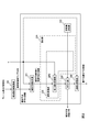
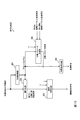
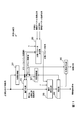
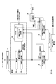
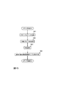
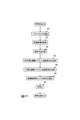
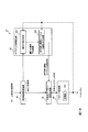
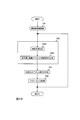
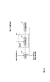
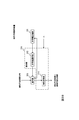
- the block diagram for demonstrating the example of a linear prediction encoding apparatus The block diagram for demonstrating the example of a linear prediction encoding apparatus.
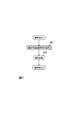
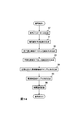
- the block diagram for demonstrating the example of a linear prediction encoding apparatus The flowchart for demonstrating the example of the linear prediction encoding method.
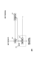
- the block diagram for demonstrating the example of a linear prediction decoding apparatus The flowchart for demonstrating the example of the linear prediction decoding method.
- the block diagram for demonstrating the example of an encoding apparatus The flowchart for demonstrating the example of the encoding method.
- the block diagram for demonstrating the example of an encoding part The block diagram for demonstrating the example of an encoding part.
- the flowchart for demonstrating the example of a process of an encoding part The block diagram for demonstrating the example of a decoding apparatus.
- the flowchart for demonstrating the example of a decoding method The flowchart for demonstrating the example of a process of a decoding part.
- the block diagram for demonstrating the example of an encoding apparatus The flowchart for demonstrating the example of an encoding apparatus.
- the flowchart for demonstrating the example of the encoding method The block diagram for demonstrating the example of a parameter determination apparatus.
- the flowchart for demonstrating the example of the parameter determination method The figure for demonstrating generalized Gaussian distribution.
- the block diagram for demonstrating the example of a linear prediction encoding apparatus The flowchart for demonstrating the example of the linear prediction encoding method.
- the block diagram for demonstrating the example of a linear prediction decoding apparatus The flowchart for demonstrating the example of the linear prediction decoding method.
- the block diagram for demonstrating the example of a linear prediction encoding apparatus The block diagram for demonstrating the example of a linear prediction encoding apparatus.
- the block diagram for demonstrating the example of a linear prediction encoding apparatus The block diagram for demonstrating the example of a linear prediction decoding apparatus.
- Linear predictive coding apparatus linear predictive decoding apparatus, and methods thereof
- a linear prediction encoding apparatus linear prediction decoding apparatus, an encoding apparatus using these methods, a decoding apparatus, and examples of these methods will be described.
- the linear prediction encoding apparatus of the first embodiment includes, for example, a linear prediction analysis unit 221, a codebook storage unit 222, an encoding unit 224, and a linear conversion unit 225.
- the frequency domain transform unit 220 is provided outside the linear predictive coding device, but the linear predictive coding device may further include the frequency domain transform unit 220.
- Each part of the linear predictive coding apparatus performs each process illustrated in FIG. 4 to realize the linear predictive coding method.
- the time domain sound signal which is a time-series signal, is input to the frequency domain transform unit 220.
- the frequency domain conversion unit 41 converts the input time domain sound signal into N frequency MDCT coefficient sequences X (0), X (1),..., X (N ⁇ Convert to 1). N is a positive integer.
- the obtained MDCT coefficient sequence X (0), X (1),..., X (N-1) is output to the linear prediction analysis unit 221.
- the subsequent processing is performed in units of frames.
- the frequency domain transforming unit 220 obtains a frequency domain sample sequence corresponding to the time series signal, for example, an MDCT coefficient sequence.
- the linear prediction analysis unit 221 receives, for example, a frequency domain sample sequence which is an MDCT coefficient sequence X (0), X (1),..., X (N-1) and a parameter ⁇ 1 corresponding to the frequency domain sample sequence. Is done.
- the parameter ⁇ 1 is a positive number.
- the parameter ⁇ 1 is determined by, for example, parameter determination units 27 and 27 ′ described later.
- the parameter ⁇ 1 is used to encode an arithmetic code in an encoding method that arithmetically encodes a quantized value of a frequency domain coefficient using a linear prediction envelope such as that used in the 3GPP EVS (Enhanced Voice Services) standard, for example.
- This is a parameter ⁇ that determines the probability distribution to which the object belongs.
- the parameter ⁇ can be an index representing the characteristics of the time series signal.
- the parameters ⁇ 2 and ⁇ 3 appearing later are also the parameter ⁇ . It can be said that ⁇ 1 , ⁇ 2 , and ⁇ 3 are predetermined values of the parameter ⁇ .
- information about the parameter ⁇ 1 is transmitted to the linear prediction decoding apparatus.
- a parameter code representing the parameter ⁇ 1 is transmitted to the linear predictive decoding device.
- the linear prediction analysis unit 221 uses the MDCT coefficient sequence X (0), X (1),..., X (N-1) and ⁇ 1 and is defined by the following equation (A7) to R (0). , ⁇ R (1), ..., ⁇ R (N-1) are used to perform linear prediction analysis to generate coefficients that can be converted into linear prediction coefficient coefficients (step DE1).
- the coefficient that can be converted into the generated linear prediction coefficient coefficient is output to the encoding unit 224.
- the linear prediction analysis unit 22 firstly performs an inverse Fourier which considers the absolute value ⁇ 1 of the MDCT coefficient sequence X (0), X (1),..., X (N ⁇ 1) as the power spectrum. Time corresponding to the absolute value of the MDCT coefficient sequence X (0), X (1), ..., X (N-1) to the ⁇ 1 power by performing the operation corresponding to the conversion, that is, the operation of the equation (A7)
- the pseudo-correlation function signal sequence ⁇ R (0), ⁇ R (1), ..., ⁇ R (N-1) which is the signal sequence of the region, is obtained.
- the linear prediction analysis unit 22 performs linear prediction analysis using the obtained pseudo correlation function signal sequence ⁇ R (0), ⁇ R (1), ..., ⁇ R (N-1) to obtain a linear prediction coefficient. Generate coefficients that can be converted to coefficients.
- the linear prediction analysis unit 221 performs inverse Fourier transform, assuming that ⁇ 1 is a positive number, and that the absolute value ⁇ 1 of the frequency domain sample sequence corresponding to the time-series signal is regarded as the power spectrum. Using the pseudo-correlation function signal sequence obtained by the above, linear prediction analysis is performed to obtain coefficients that can be converted into linear prediction coefficients.
- the coefficients that can be converted into linear prediction coefficients are, for example, LSP, PARCOR coefficient, ISP, and the like.
- the coefficient that can be converted into the linear prediction coefficient may be the linear prediction coefficient itself.
- p is a predetermined positive number
- the possible degree of the linear prediction coefficient is p-th order.
- the codebook storage unit 222 stores a codebook in which a plurality of coefficient candidates that can be converted into linear prediction coefficients corresponding to the parameter ⁇ 2 are stored.
- a pair of a coefficient candidate that can be converted into a linear prediction coefficient and a code corresponding to the coefficient candidate that can be converted into the linear prediction coefficient will be referred to as a candidate code pair.
- a plurality of candidate code pairs are stored in the codebook. In other words, when N is a predetermined number of 2 or more, N candidate pairs are stored in the codebook.
- a predetermined number of bits are assigned to each code corresponding to a coefficient candidate that can be converted into a linear prediction coefficient. Each code is represented by a predetermined number of assigned bits.
- each coefficient candidate that can be converted into the linear prediction coefficient is composed of p values.
- a candidate coefficient that can be converted to a linear prediction coefficient corresponding to parameter ⁇ 2 is optimal for encoding a coefficient that can be converted to a linear prediction coefficient corresponding to a frequency domain sample sequence having a parameter ⁇ value of ⁇ 2 This is a coefficient candidate that can be converted into a linear prediction coefficient.
- the linear conversion unit 225 receives a coefficient that can be converted into the linear prediction coefficient obtained by the linear prediction analysis unit 221 and a parameter ⁇ 1 corresponding to the coefficient that can be converted into the linear prediction coefficient.
- the parameter ⁇ 1 is determined by, for example, parameter determination units 27 and 27 ′ described later.
- the linear conversion unit 225 includes at least one of a first linear conversion unit 2251 and a second linear conversion unit 2252.
- the linear conversion unit 225 includes the first linear conversion unit 2251 as shown in FIG. 1
- the linear conversion unit 225 is the second case as shown in FIG.
- the case where the linear conversion unit 2252 is provided is the second case
- Each case will be described as the case 3.
- the first linear conversion unit 2251 of the linear conversion unit 225 has at least input parameters for coefficient candidates that can be converted into linear prediction coefficients stored in the codebook storage unit 222.
- a first linear transformation corresponding to ⁇ 1 is performed (step DE2).
- the first linear conversion unit 2251 performs the first linear conversion according to the input parameter ⁇ 1 and the parameter ⁇ 2 corresponding to the coefficient candidate that can be converted into the linear prediction coefficient stored in the codebook storage unit 222.
- the coefficient candidate that can be converted into the linear prediction coefficient corresponding to the parameter ⁇ 2 read from the codebook storage unit 222 is converted into the coefficient candidate that can be converted into the linear prediction coefficient corresponding to the parameter ⁇ 1 .
- Coefficient candidates that can be converted to linear prediction coefficients corresponding to parameter ⁇ 1 are optimal for encoding coefficients that can be converted to linear prediction coefficients corresponding to the frequency domain sample sequence whose parameter ⁇ is ⁇ 1 This is a coefficient candidate that can be converted into a linear prediction coefficient.
- the candidate coefficients that can be converted into the linear prediction coefficients after the first linear conversion are output to the encoding unit 224.
- the first linear conversion unit 2251 may not perform the first linear conversion.
- the first linear transformation unit 2251 of the linear transformation section 225 in accordance with the input parameter eta 1, as parameter eta 1 is small with the input can be converted into linear prediction coefficients after the first linear transformation First linear conversion is performed on the coefficient candidates that can be converted into the linear prediction coefficients read from the codebook storage unit 222 so that the amplitude spectrum envelope series corresponding to the coefficient candidates becomes flat, and the converted linear Coefficient candidates that can be converted into prediction coefficients are output.
- the coefficient that can be converted into the linear prediction coefficient is LSP
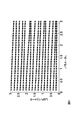
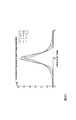
- Fig. 5 shows an example of LSP parameter values when parameter ⁇ takes various values.
- the horizontal axis in FIG. 5 is the parameter ⁇ , and the vertical axis is the LSP parameter.
- FIG. 5 shows that the smaller the parameter ⁇ , the closer the LSP parameter approaches a value obtained by equally dividing 0 to ⁇ .
- the second linear conversion unit 2252 of the linear conversion unit 225 uses at least the input parameter ⁇ 1 for the coefficient that can be converted into the linear prediction coefficient obtained by the linear prediction analysis unit 221.
- the second linear transformation is performed according to (step DE2).
- the second linear conversion unit 2252 can convert a coefficient that can be converted into a linear prediction coefficient corresponding to the parameter ⁇ 1 obtained by the linear prediction analysis unit 221 into a linear prediction coefficient stored in the codebook storage unit 222. In order to correspond to a candidate of a new coefficient, the second linear conversion is performed to a coefficient that can be converted into a linear prediction coefficient corresponding to the parameter ⁇ 2 .
- the coefficient that can be converted into the linear prediction coefficient after the second linear conversion is output to the encoding unit 224.
- the second linear conversion unit 2252 may not perform the second linear conversion.
- the second linear transformation unit 2252 of the linear transformation section 225 in accordance with the input parameter eta 1, the smaller the inputted parameter eta 1, can be converted into linear prediction coefficients after the second linear transformation Second linear transformation is performed on the coefficients that can be converted to linear prediction coefficients so that the series of amplitude spectrum envelopes corresponding to the coefficients is flat, and the coefficients that can be converted to linear prediction coefficients after conversion are output. To do.
- the first linear conversion unit 2251 of the linear conversion unit 225 sets at least the parameter ⁇ 3 to the coefficient candidates that can be converted into the linear prediction coefficients stored in the codebook storage unit 222.
- a first linear transformation is performed.
- the parameter ⁇ 3 is a positive value, and a value different from the parameter ⁇ 2 is determined in advance or input from the outside of the linear prediction coefficient encoding device.
- the first linear transformation unit 2251 a first linear transformation in accordance with the parameter eta 2 corresponding to the candidate parameter eta 3 and codebook can be converted to a linear prediction coefficient stored in the storage unit 222 coefficients, code A coefficient candidate that can be converted into a linear prediction coefficient corresponding to the parameter ⁇ 2 read from the book storage unit 222 is converted into a coefficient candidate that can be converted into a linear prediction coefficient corresponding to the parameter ⁇ 3 .
- Coefficient candidates that can be converted to linear prediction coefficients corresponding to parameter ⁇ 3 are optimal for encoding coefficients that can be converted to linear prediction coefficients corresponding to the frequency domain sample sequence whose parameter ⁇ is ⁇ 3 This is a coefficient candidate that can be converted into a linear prediction coefficient.
- the candidate coefficients that can be converted into the linear prediction coefficients after the first linear conversion are output to the encoding unit 224.
- the first linear conversion unit 2251 may not perform the first linear conversion.
- the first linear conversion unit 2251 of the linear conversion unit 225 has a flatter amplitude spectrum envelope corresponding to a coefficient candidate that can be converted into a linear prediction coefficient after the first linear conversion, as the parameter ⁇ 3 is smaller.
- the first linear conversion is performed on the coefficient candidates that can be converted into the linear prediction coefficients read from the codebook storage unit 222, and the coefficient candidates that can be converted into the converted linear prediction coefficients are output.
- the second linear conversion unit 2252 of the linear conversion unit 225 has a second value corresponding to at least the parameter ⁇ 1 with respect to the coefficient that can be converted into the linear prediction coefficient obtained by the linear prediction analysis unit 221. Perform linear transformation.
- the second linear conversion unit 2252 converts the coefficient that can be converted into the linear prediction coefficient corresponding to the parameter ⁇ 1 obtained by the linear prediction analysis unit 221 into the coefficient that can be converted into the linear prediction coefficient corresponding to the parameter ⁇ 3. Second linear transformation.
- the candidate coefficients that can be converted into the linear prediction coefficients after the second linear conversion are output to the encoding unit 224.
- second linear conversion unit 2252 may not perform the second linear conversion.
- the second linear transformation unit 2252 of the linear transformation section 225 in accordance with the input parameter eta 1, the smaller the inputted parameter eta 1, can be converted into linear prediction coefficients after the second linear transformation
- the second linear transformation is performed on the input coefficient that can be converted into the linear prediction coefficient so that the amplitude spectrum envelope corresponding to the coefficient becomes flat, and the coefficient that can be converted into the converted linear prediction coefficient is output.
- the linear conversion unit 225 performs the first linear operation according to ⁇ 3 on the coefficient candidates that can be converted into the linear prediction coefficients stored in the codebook storage unit 222. At least one of the conversion and the second linear conversion corresponding to ⁇ 3 is performed on the coefficient that can be converted into the linear prediction coefficient obtained by the linear prediction analysis unit 221 (step DE2).
- ⁇ Encoding unit 224 The processing of the encoding unit 224 differs depending on the configuration of the linear conversion unit 225. Therefore, the processing of the encoding unit 224 when the linear conversion unit 225 is (1) the first case, (2) the second case, and (3) the third case will be described below.
- the encoding unit 224 includes a coefficient that can be converted into the linear prediction coefficient obtained by the linear prediction analysis unit 221 and a linear conversion unit. Coefficient candidates that can be converted into linear prediction coefficients after the first linear conversion obtained by the first linear conversion unit 2251 of 225 are input.
- the encoding unit 224 encodes a coefficient that can be converted into a linear prediction coefficient using a coefficient candidate that can be converted into a linear prediction coefficient after the first linear conversion to obtain a linear prediction coefficient code (step DE3).
- the encoding unit 224 selects a candidate closest to a coefficient that can be converted into a linear prediction coefficient from among a plurality of coefficient candidates that can be converted into a linear prediction coefficient after the first linear conversion.
- the code corresponding to the selected candidate is a linear prediction coefficient code.
- the obtained linear prediction coefficient code is output to the decoding device.
- the encoding unit 224 can convert the linear prediction coefficient obtained by the second linear conversion unit 2252 of the linear prediction analysis unit 221. And a coefficient candidate that can be converted into a linear prediction coefficient stored in the codebook storage unit 222 is input.
- the encoding unit 224 encodes a coefficient that can be converted into a linear prediction coefficient after the second linear conversion using a coefficient candidate that can be converted into a linear prediction coefficient to obtain a linear prediction coefficient code (step DE3).
- the encoding unit 224 selects a candidate closest to the coefficient that can be converted into the linear prediction coefficient after the second linear conversion from among a plurality of coefficient candidates that can be converted into the linear prediction coefficient.
- the code corresponding to the selected candidate is a linear prediction coefficient code.
- the obtained linear prediction coefficient code is output to the decoding device.
- the encoding unit 224 can convert the linear prediction coefficient obtained by the second linear conversion unit 2252 of the linear prediction analysis unit 221. And a coefficient candidate that can be converted into a linear prediction coefficient obtained by the first linear conversion unit 2251 of the linear prediction analysis unit 221 is input.
- the encoding unit 224 encodes a coefficient that can be converted into the linear prediction coefficient after the second linear conversion using a coefficient candidate that can be converted into the linear prediction coefficient after the first linear conversion to obtain a linear prediction coefficient code. (Step DE3).
- the encoding unit 224 converts the coefficient that can be converted into the linear prediction coefficient after the second linear conversion, from among a plurality of coefficient candidates that can be converted into the linear prediction coefficient after the first linear conversion. The closest one is selected, and the code corresponding to the selected candidate is set as the linear prediction coefficient code.
- the obtained linear prediction coefficient code is output to the decoding device.
- the parameter ⁇ corresponding to the coefficient that can be converted into a linear prediction coefficient and the linear prediction coefficient are used.
- the linear predictive decoding apparatus includes, for example, a codebook storage unit 311, a decoding unit 313, and a linear conversion unit 314.
- Each unit of the linear predictive decoding apparatus performs each process illustrated in FIG. 7 to realize the linear predictive decoding method.
- the codebook storage unit 311 stores the same codebook as the codebook stored in the codebook storage unit 222. That is, the codebook storage unit 311 stores a codebook in which a plurality of coefficient candidates that can be converted into linear prediction coefficients corresponding to the parameter ⁇ 2 are stored.
- the decoding unit 313 receives the linear prediction coefficient code output from the linear prediction encoding apparatus.
- the decoding unit 313 is a coefficient candidate that can be converted into a linear prediction coefficient corresponding to the input linear prediction coefficient code, among coefficient candidates that can be converted into a plurality of linear prediction coefficients stored in the codebook storage unit 311. Are obtained as coefficients that can be converted into linear prediction coefficients (step DD1).
- the obtained coefficient that can be converted into the linear prediction coefficient is output to the linear conversion unit 314.
- the obtained coefficient that can be converted into a linear prediction coefficient is any one of coefficient candidates that can be converted into a plurality of linear prediction coefficients corresponding to the parameter ⁇ 2 stored in the codebook storage unit 311. For this reason, the coefficient that can be converted into the linear prediction coefficient obtained by the decoding unit 313 is a coefficient that can be converted into the linear prediction coefficient corresponding to the parameter ⁇ 2 .
- ⁇ Linear conversion unit 314 A coefficient that can be converted into a linear prediction coefficient corresponding to the parameter ⁇ 2 obtained by the decoding unit 313 and the parameter ⁇ 1 are input to the linear conversion unit 314.
- This parameter ⁇ 1 is obtained, for example, by decoding a parameter code received from the linear predictive coding apparatus.
- the linear conversion unit 314 performs a linear conversion according to at least the parameter ⁇ 1 on the coefficient that can be converted into the linear prediction coefficient corresponding to the parameter ⁇ 2 to obtain a coefficient that can be converted into a linear prediction coefficient after the linear conversion. .
- the linear conversion unit 314 can convert a linear prediction coefficient corresponding to the parameter ⁇ 2 by linear conversion according to the input parameter ⁇ 1 and the parameter ⁇ 2 corresponding to the coefficient that can be converted into the linear prediction coefficient.
- the coefficient is converted into a coefficient that can be converted into a linear prediction coefficient corresponding to the parameter ⁇ 1 .
- the obtained coefficient that can be converted into the linear prediction coefficient after the linear conversion is output as a decoding result by the linear prediction decoding apparatus or method.
- the linear conversion unit 314 may not perform linear conversion.
- the linear conversion unit 3144 when obtaining the linear convertible to prediction coefficients coefficients corresponding coefficients that can be converted to a linear prediction coefficient corresponding to the parameter eta 2 to be a linear transformation parameters eta 1, parameter eta 1 both A configuration may be adopted in which linear transformation is performed a plurality of times using a parameter ⁇ 4 different from the parameter ⁇ 2 .
- the linear conversion unit 314 linearly converts a coefficient that can be converted into a linear prediction coefficient corresponding to the parameter ⁇ 2 to obtain a coefficient that can be converted into a linear prediction coefficient corresponding to the parameter ⁇ 4 . Further, the linear conversion unit 314 linearly converts the obtained coefficient that can be converted into a linear prediction coefficient corresponding to the parameter ⁇ 4 to obtain a coefficient that can be converted into a linear prediction coefficient corresponding to the parameter ⁇ 1 .
- the linear conversion unit 225 of the linear prediction coefficient encoding device in the third case is converted into two linear conversions.
- the same linear transformation can be used as the linear transformation that obtains the coefficient that can be transformed into the linear prediction coefficient corresponding to the parameter ⁇ 3 by converting the coefficient that can be transformed into the linear prediction coefficient corresponding to the parameter ⁇ 1. .
- the linear conversion unit 314 performs linear prediction corresponding to the parameter ⁇ 2 by combining one linear conversion obtained by combining the linear conversion from the parameter ⁇ 2 to the parameter ⁇ 3 and the linear conversion from the parameter ⁇ 3 to the parameter ⁇ 1 .
- a coefficient that can be converted into a linear prediction coefficient corresponding to the parameter ⁇ 1 may be obtained by using a coefficient that can be converted into a coefficient.
- the obtained coefficient that can be converted into a linear prediction coefficient corresponding to the parameter ⁇ 1 is output as a decoding result by the linear prediction decoding apparatus or method.
- the linear conversion unit 31 like the linear conversion unit 225 of the linear predictive encoding device, the amplitude spectrum corresponding to the coefficient that can be converted into the linear prediction coefficient after the linear conversion as the input ⁇ 1 is smaller.
- a coefficient that can be converted into a linear prediction coefficient after linear conversion may be obtained by linearly converting the coefficient that can be converted into the linear prediction coefficient obtained by the decoding unit 313 so that the envelope becomes flat.
- the coefficient that can be converted into the linear prediction coefficient after the linear conversion obtained by the linear conversion unit 314 is the amplitude spectrum envelope series corresponding to the coefficient that can be converted into the linear prediction coefficient obtained by the linear conversion unit 314. used to obtain the non-smoothed spectral envelope sequence is 1 squared series.
- the 1st linear transformation part 2251, the 2nd linear transformation part 2252, the inverse linear transformation part 226, and the linear transformation part 314 perform the linear transformation shown, for example by the following formula
- x 1 , x 2 , ... x p , y 1 , y 2 , ... y p-1 , z 2 , z 3 , ... z p are predetermined non-negative numbers and y 1 , y 2 , ... y p-1, z 2, z 3, ... at least one of z p is assumed to be the number of a predetermined positive, x 1, x 2 and K, ... x p, y 1 , y 2, ... y p-1 , z 2 , z 3 ,... z p is a matrix whose elements are 0.
- x 1 , x 2 , ... x p , y 1 , y 2 , ... y p-1 , z 2 , z 3 , ... z p are specific values that can be converted to linear prediction coefficients before linear transformation
- parameter ⁇ hereinafter referred to as parameter ⁇ A before linear conversion
- X 1 , x 2 , ... x p , y 1 , y 2 , ... y p-1 , z 2 , z 3 corresponding to a plurality of different sets of pre-linear transformation parameter ⁇ A and post-linear transformation parameter ⁇ B ,... Z p is stored in advance in a storage unit (not shown).
- the first linear conversion unit 2251, the second linear conversion unit 2252, the inverse linear conversion unit 226, and the linear conversion unit 314 perform linear conversion, the pre-linear conversion parameter ⁇ A and the post-linear conversion parameter ⁇ B in the linear conversion are performed.
- X 1 , x 2 ,... x p , y 1 , y 2 ,... y p ⁇ 1 , z 2 , z 3 ,... z p corresponding to the pair and read these values May be used to perform linear transformation according to the above equation.
- the first linear conversion unit 2251 of the linear conversion unit 225 performs the first linear conversion so that the order of the coefficient candidates that can be converted into the linear prediction coefficient after the first linear conversion becomes smaller as the parameter ⁇ 1 is smaller. You may go.
- the linear conversion unit 314 may perform linear conversion so that the order of the coefficient that can be converted into the linear prediction coefficient after the linear conversion becomes smaller as the parameter ⁇ 1 is smaller.
- the coefficients that can be converted to the linear prediction coefficients before the linear conversion before the linear conversion or the candidate orders of the coefficients that can be converted to the linear prediction coefficients, and the coefficients or the linear prediction that can be converted to the linear prediction coefficients after the linear conversion Linear conversion may be performed so that the order of coefficient candidates that can be converted into coefficients is different.
- the first linear conversion unit 2251 reduces the order of candidate coefficients that can be converted into linear prediction coefficients after linear conversion after performing linear conversion in which the order before linear conversion is the same as the order after linear conversion. May be. In addition, the first linear conversion unit 2251 performs linear conversion in which the order before linear conversion and the order after linear conversion are the same after reducing the order of coefficient candidates that can be converted into linear prediction coefficients after linear conversion. May be.
- the linear conversion unit 314 may reduce the order of coefficients that can be converted into linear prediction coefficients after linear conversion after performing linear conversion in which the order before linear conversion is the same as the order after linear conversion. .
- the linear conversion unit 314 may perform linear conversion in which the order before linear conversion and the order after linear conversion are the same after reducing the order of coefficients that can be converted into linear prediction coefficients after linear conversion.
- the first linear transformation unit 2251 if the parameter eta 1 is small, by integrating a plurality of candidates of convertible coefficient to the linear predictive coefficients after the linear transformation, after the linear transformation as the parameter eta 1 is small The number of candidates for coefficients that can be converted to the linear prediction coefficient may be reduced.
- the linear predictive encoding apparatus includes, for example, a linear predictive analysis unit 221, a codebook storage unit 222, a codebook selection unit 223, and an encoding unit 224.
- the frequency domain transform unit 220 is provided outside the linear predictive coding device, but the linear predictive coding device may further include the frequency domain transform unit 220.
- Each part of the linear predictive coding apparatus performs each process illustrated in FIG. 22 to realize the linear predictive coding method.
- the time domain sound signal which is a time-series signal, is input to the frequency domain transform unit 220.
- the frequency domain conversion unit 41 converts the input time domain sound signal into N frequency MDCT coefficient sequences X (0), X (1),..., X (N ⁇ Convert to 1). N is a positive integer.
- the obtained MDCT coefficient sequence X (0), X (1),..., X (N-1) is output to the linear prediction analysis unit 221.
- the subsequent processing is performed in units of frames.
- the frequency domain transforming unit 220 obtains a frequency domain sample sequence corresponding to the time series signal, for example, an MDCT coefficient sequence.
- the linear prediction analysis unit 221 receives a frequency domain sample sequence, for example, an MDCT coefficient sequence X (0), X (1),..., X (N-1) and a parameter ⁇ corresponding to the frequency domain sample sequence.
- a frequency domain sample sequence for example, an MDCT coefficient sequence X (0), X (1),..., X (N-1) and a parameter ⁇ corresponding to the frequency domain sample sequence.
- the parameter ⁇ is a positive number.
- the parameter ⁇ is determined by, for example, parameter determination units 27 and 27 'described later.
- the parameter ⁇ is the encoding target of the arithmetic code in the encoding scheme that arithmetically encodes the quantized value of the frequency domain coefficient using the linear prediction envelope as used in the 3GPP3EVS (Enhanced Voice Services) standard, for example.
- the linear prediction analysis unit 221 is defined by the following equation (A7) using the MDCT coefficient sequence X (0), X (1),..., X (N-1) and ⁇ .
- a coefficient that can be converted into a linear prediction coefficient is generated by performing linear prediction analysis using ⁇ R (0), ⁇ R (1), ..., ⁇ R (N-1) (step DE1).
- the coefficient that can be converted into the generated linear prediction coefficient is output to the encoding unit 224.
- the linear prediction analysis unit 22 firstly performs an inverse Fourier transform in which the absolute value of the MDCT coefficient sequence X (0), X (1),. , That is, in the time domain corresponding to the absolute value of MDCT coefficient sequence X (0), X (1), ..., X (N-1) to the ⁇ th power A pseudo-correlation function signal sequence ⁇ R (0), ⁇ R (1), ..., ⁇ R (N-1) which is a signal string is obtained. Then, the linear prediction analysis unit 22 performs linear prediction analysis using the obtained pseudo correlation function signal sequence ⁇ R (0), ⁇ R (1), ..., ⁇ R (N-1) to obtain a linear prediction coefficient. Generate coefficients that can be converted to.
- the linear prediction analysis unit 221 obtains ⁇ as a positive number and performs an inverse Fourier transform assuming that the absolute value of the ⁇ power of the frequency domain sample sequence corresponding to the time-series signal is a power spectrum.
- a coefficient that can be converted into a linear prediction coefficient is obtained by performing a linear prediction analysis using the generated pseudo correlation function signal sequence.
- the coefficients that can be converted into linear prediction coefficients are, for example, LSP, PARCOR coefficient, ISP, and the like.
- the coefficient that can be converted into the linear prediction coefficient may be the linear prediction coefficient itself.
- p is a predetermined positive number
- the possible degree of the linear prediction coefficient is p-th order.
- the codebook storage unit 222 stores a plurality of codebooks.
- each codebook stores a plurality of candidate code pairs.
- I is a predetermined number of 2 or more and N i is a predetermined number of 2 or more determined according to i
- a predetermined number of bits are assigned to each code corresponding to a coefficient candidate that can be converted into a linear prediction coefficient.
- Each code is represented by a predetermined number of assigned bits.
- each coefficient candidate that can be converted into the linear prediction coefficient is composed of p values.
- the plurality of codebooks stored in the codebook storage unit 222 differ depending on the codebook selection method of the codebook selection unit 223. Therefore, an example of a plurality of code books stored in the code book storage unit 222 will be described together with an example of a code book selection unit 223 described later.
- the code book selection unit 223 receives the parameter ⁇ .
- the codebook selection unit 223 selects a codebook from a plurality of codebooks stored in the codebook storage unit 222 according to ⁇ input (step DE2). Information about the selected codebook is output to the encoding unit 224.
- the codebook storage unit 222 stores a plurality of codebooks with different numbers of coefficient candidates that can be converted into linear prediction coefficients. Also, the codebook selection unit 223 selects a codebook having a larger number of coefficient candidates that can be converted into linear prediction coefficients from a plurality of codebooks stored in the codebook storage unit 222 as the parameter ⁇ increases. .
- the parameter ⁇ when the parameter ⁇ is small, the range of coefficients that can be converted to linear prediction coefficients tends to be narrow, so it can be converted to linear prediction coefficients with a small number of coefficient candidates that can be converted to linear prediction coefficients. It is possible to express various coefficients. For this reason, when the parameter is small, even if encoding and decoding are performed using a codebook with a small number of coefficient candidates that can be converted into linear prediction coefficients, the quantization distortion is small, so the encoding and decoding accuracy is not so high. It doesn't get worse.
- the codebook selection unit 223 increases the number of coefficient candidates that can be converted into linear prediction coefficients from among a plurality of codebooks stored in the codebook storage unit 222 as the parameter ⁇ increases. Select a codebook with many.
- the determination about the size of the parameter ⁇ in other words, selection of an appropriate codebook can be made based on a threshold value. For example, it is assumed that the number of coefficient candidates that can be converted into linear prediction coefficients in the first codebook is smaller than the number of coefficient candidates that can be converted into linear prediction coefficients in the second codebook. In this case, one threshold value of the parameter ⁇ is determined in advance, and when the input parameter ⁇ is smaller than the threshold value, it is determined that the parameter ⁇ is small and the first codebook is selected. If the input parameter ⁇ is greater than or equal to the threshold, it is determined that the parameter ⁇ is large and the second codebook is selected. When the number of codebooks is 3 or more, the codebook may be selected in the same manner using the threshold value of the number obtained by subtracting 1 from the number of codebooks.
- the parameter ⁇ when the parameter ⁇ is large, the first layer and the second layer are used, and when the parameter ⁇ is small, only the first layer is used.
- the determination of whether the parameter ⁇ is large or small can be made based on the threshold value as described above.
- the coefficient that can be converted to the linear prediction coefficient of the first layer and the code corresponding to the coefficient that can be converted to the input linear prediction coefficient are selected.
- the one closest to the subtraction value and the corresponding code are selected.
- the two codes selected in the first layer and the second layer are linear prediction coefficient codes. That is, the linear prediction coefficient code is expressed by 15 bits.
- the sum of the coefficient candidates that can be converted into the linear prediction coefficients selected in the first layer and the second layer is the quantization result of the coefficients that can be converted into the input linear prediction coefficients.
- the coefficient that can be converted to the linear prediction coefficient of the first layer and the code corresponding to the coefficient that can be converted to the input linear prediction coefficient are selected.
- the code selected in the first layer is the linear prediction coefficient code. That is, the linear prediction coefficient code is expressed by 10 bits.
- the coefficient candidates that can be converted into the linear prediction coefficients selected in the first layer are the quantization results of the coefficients that can be converted into the input linear prediction coefficients.
- this example is also an example of (1) the first method.
- the search range of candidate code pairs in one codebook is variable.
- the search range of candidate code pairs may be narrowed as the parameter ⁇ is small.
- the codebook storage unit 222 stores, in the 1 / ⁇ power, a series of amplitude spectrum envelopes corresponding to coefficient candidates that can be converted into linear prediction coefficients stored in the codebook.
- a plurality of codebooks having different degrees of flatness of the non-smoothed spectrum envelope sequence, which is the obtained sequence, are stored.
- the codebook selection unit 223 corresponds to a coefficient candidate that can be converted into a linear prediction coefficient stored in the codebook from a plurality of codebooks stored in the codebook storage unit 222 as ⁇ is smaller.
- a codebook is selected in which the non-smoothed spectrum envelope sequence, which is a sequence obtained by raising the amplitude spectrum envelope sequence to the power of 1 / ⁇ , is flatter.
- the coefficient that can be converted into a linear prediction coefficient is LSP
- Fig. 5 shows an example of LSP parameter values when parameter ⁇ takes various values.
- the horizontal axis in FIG. 5 is the parameter ⁇ , and the vertical axis is the LSP parameter.
- FIG. 5 shows that the smaller the parameter ⁇ , the closer the LSP parameter approaches a value obtained by equally dividing 0 to ⁇ .
- the coefficients that can be converted into linear prediction coefficients are ISP parameters. That is, when the coefficient that can be converted into the linear prediction coefficient is an ISP parameter, the smaller the parameter ⁇ , the closer the coefficient that can be converted into the linear prediction coefficient that is the ISP parameter is closer to a value obtained by equally dividing 0 to ⁇ .
- the coefficient that can be converted into the linear prediction coefficient is a PARCOR coefficient
- the smaller the parameter ⁇ the smaller the coefficient that can be converted into the linear prediction coefficient that is the PARCOR coefficient as a whole.
- the second method uses these tendencies, and encodes and decodes using candidate coefficients that can be converted into linear prediction coefficients corresponding to the case where the unsmoothed spectrum envelope sequence is flatter as the parameter ⁇ is smaller. By trying to improve the quantization performance.
- Coefficients that can be converted into linear prediction coefficients corresponding to the flattest non-smoothed spectral envelope are denoted as ⁇ F [1], ⁇ F [2], ..., ⁇ F [p].
- selection of an appropriate codebook may be performed based on a threshold value.
- the non-smoothed spectrum envelope sequence which is a sequence obtained by raising the amplitude spectrum envelope sequence corresponding to the candidate coefficients that can be converted into the linear prediction coefficients of the first codebook to the 1 / ⁇ power, is linear in the second codebook.
- the amplitude spectrum envelope sequence corresponding to the coefficient candidates that can be converted into prediction coefficients is flatter than the unsmoothed spectrum envelope sequence that is a sequence obtained by raising the power to 1 / ⁇ .
- one threshold value of the parameter ⁇ is determined in advance, and when the input parameter ⁇ is smaller than the threshold value, it is determined that the parameter ⁇ is small and the first codebook is selected. If the input parameter ⁇ is greater than or equal to the threshold, it is determined that the parameter ⁇ is large and the second codebook is selected.
- the codebook may be selected in the same manner using the threshold value of the number obtained by subtracting 1 from the number of codebooks.
- the codebook storage unit 222 stores a plurality of codebooks having different intervals between candidate coefficients that can be converted into linear prediction coefficients. Further, the codebook selection unit 223 selects a codebook having a smaller interval between coefficient candidates that can be converted into linear prediction coefficients from a plurality of codebooks stored in the codebook storage unit 222 as ⁇ decreases. To do.
- the interval between coefficient candidates that can be converted into linear prediction coefficients is any index that represents the width of the interval between coefficient candidates that can be converted into linear prediction coefficients included in the codebook. May be.
- the interval between coefficient candidates that can be converted to a linear prediction coefficient is the coefficient candidate that can be converted into a certain linear prediction coefficient and the coefficient candidate that can be converted into another linear prediction coefficient. May be an average value of the distance to the distance, or may be a maximum value, a minimum value, or a median value of the distance.
- the third method uses this tendency.
- the interval between coefficient candidates that can be converted into linear prediction coefficients is the average value of the distances between coefficient candidates that can be converted into two adjacent linear prediction coefficients included in the codebook. It may be.
- an appropriate codebook may be selected based on a threshold value. For example, it is assumed that the interval between coefficient candidates that can be converted into linear prediction coefficients in the first codebook is narrower than the interval between coefficient candidates that can be converted into linear prediction coefficients in the second codebook.
- one threshold value of the parameter ⁇ is determined in advance, and when the input parameter ⁇ is smaller than the threshold value, it is determined that the parameter ⁇ is small and the first codebook is selected. If the input parameter ⁇ is greater than or equal to the threshold, it is determined that the parameter ⁇ is large and the second codebook is selected.
- the codebook may be selected in the same manner using the threshold value of the number obtained by subtracting 1 from the number of codebooks.
- Coding section 224 receives information about the coefficients that can be converted into linear prediction coefficients obtained by linear prediction analysis section 221 and the selected codebook obtained by codebook selection section 223.
- the encoding unit 224 encodes a coefficient that can be converted into a linear prediction coefficient using the selected codebook to obtain a linear prediction coefficient code (step DE3).
- the obtained linear prediction coefficient code is output to the decoding device.
- the linear predictive decoding apparatus includes, for example, a codebook storage unit 311, a codebook selection unit 312 and a decoding unit 313.
- Each unit of the linear predictive decoding apparatus performs each process illustrated in FIG. 24 to realize the linear predictive decoding method.
- the code book storage unit 311 stores a plurality of code books.
- Each codebook stores a plurality of candidate code pairs.
- Candidate pairs are stored.
- a predetermined number of bits are assigned to each code corresponding to a coefficient candidate that can be converted into a linear prediction coefficient.
- Each code is represented by a predetermined number of assigned bits.
- the coefficient candidates that can be converted into linear prediction coefficients are composed of p values.
- the plurality of codebooks stored in the codebook storage unit 311 differ depending on the codebook selection method of the codebook selection unit 312. Therefore, an example of a plurality of code books stored in the code book storage unit 311 will be described together with an example of a code book selection unit 312 described later.
- the codebook storage unit 311 stores the same codebook as the plurality of codebooks stored in the codebook storage unit 222.
- the code book selection unit 312 receives the parameter ⁇ .
- the parameter ⁇ is obtained by decoding the parameter code.
- the parameter ⁇ may be the same number predetermined by the encoding device and the decoding device.
- the codebook selection unit 312 selects a codebook according to ⁇ input from among a plurality of codebooks stored in the codebook storage unit 311 (step DD1). Information about the selected codebook is output to the decoding unit 313.
- the codebook storage unit 311 stores the same codebook as a plurality of codebooks stored in the codebook storage unit 222. Further, it is assumed that the same selection criteria as the codebook selection criteria by the codebook selection unit 223 of the encoding device are set in the codebook selection unit 312 in advance. As a result, a codebook having the same contents as the codebook selected on the code side is also selected on the decoding side.
- the decoding unit 313 receives the linear prediction coefficient code output from the encoding device and information on the selected codebook obtained by the codebook selection unit 312. The decoding unit 313 reads the code book specified by the information about the selected code book by the code book storage unit 311.
- the decoding unit 313 obtains a coefficient that can be converted into a linear prediction coefficient by decoding the linear prediction coefficient code by using the selected codebook (step DD2).
- the coefficient that can be converted into a linear prediction coefficient is used to obtain a non-smoothed spectrum envelope sequence that is a series obtained by raising the amplitude spectrum envelope sequence corresponding to the coefficient that can be converted into a linear prediction coefficient to the power of 1 / ⁇ .
- the adapting unit 22A includes at least one of the codebook selecting unit 223 and the linear conversion unit 225, the adapting unit 22A Is adapted to match at least one of the codebook stored in the codebook storage unit 222 and the coefficient that can be converted into the linear prediction coefficient generated by the linear prediction analysis unit 221 based on the inputted ⁇ 1 . It can be said.
- the matching unit 22A uses a plurality of candidates for coefficients that can be converted into linear prediction coefficients stored in the codebook stored in the codebook storage unit 22 and the linear prediction coefficients obtained by the linear prediction analysis unit 221. It can be said that the convertible coefficient is matched with the value of ⁇ .
- the matching unit 22A may include, for example, a codebook stored in the codebook storage unit 222 before matching, that is, a parameter ⁇ value corresponding to a plurality of candidates for coefficients that can be converted into linear prediction coefficients, and linear prediction analysis.
- the adapting unit 22A performs the adaptation so that the values of the two parameters ⁇ are substantially the same after the adaptation.
- the processing of the first linear conversion unit 2251 of the linear conversion unit 225 described in the first embodiment and the processing of the code book selection unit 223 described in the second embodiment are adapted to the code book stored in the code book storage unit 222. It is an example.
- the processing of the second linear conversion unit 2252 of the linear conversion unit 225 described in the second embodiment is an example of adaptation of coefficients that can be converted into linear prediction coefficients generated by the linear prediction analysis unit 221.
- the encoding unit 224 performs encoding using at least one codebook adapted by the adaptation unit 22A and a coefficient that can be converted into a linear prediction coefficient.
- the encoding unit 224 uses the codebook selected by the codebook selection unit 223 or the codebook adapted by the adaptation unit 22A, and the coefficient or adaptation that can be converted into the linear prediction coefficient by the linear prediction analysis unit 221. It can be said that the coefficient that can be converted into the linear prediction coefficient adapted by the unit 22A is encoded.
- the encoding unit 224 uses a plurality of candidates for coefficients that can be converted into linear prediction coefficients to which the value of ⁇ is adapted and a coefficient that can be converted into linear prediction coefficients, and then uses the linear prediction analysis unit 221. It can be said that the linear prediction coefficient code corresponding to the coefficient that can be converted into the linear prediction coefficient obtained is obtained.
- the adapting unit 22A in the first case performs a first linear transformation corresponding to ⁇ 1 on a coefficient candidate that can be transformed into a linear prediction coefficient stored in the codebook storage unit 222. It can be said that a linear conversion unit 225 that obtains a plurality of candidates of coefficients that can be converted into linear prediction coefficients after the first linear conversion is provided.
- the encoding unit 224 includes a plurality of coefficients that can be converted into the linear prediction coefficient obtained by the linear prediction analysis unit 221 and the coefficient that can be converted into the linear prediction coefficient after the first linear conversion obtained by the adaptation unit 22A. It can be said that the linear prediction coefficient code corresponding to the coefficient that can be converted into the linear prediction coefficient obtained by the linear prediction analysis unit 221 is obtained using the candidates.
- the adapting unit 22A in the second case (2) of the first embodiment performs the second linear transformation according to ⁇ 1 on the coefficient that can be converted into the linear prediction coefficient obtained by the linear prediction analysis unit 221; It can be said that the linear conversion part 225 which obtains the coefficient which can be converted into the linear prediction coefficient after 2nd linear conversion is provided.
- the encoding unit 224 has a plurality of candidates for the coefficient that can be converted into the linear prediction coefficient after the second linear conversion obtained by the adaptation unit 22A and the coefficient that can be converted into the linear prediction coefficient stored in the codebook.
- the linear prediction coefficient code corresponding to the coefficient that can be converted into the linear prediction coefficient obtained by the linear prediction analysis unit 221 is obtained.
- the adapting unit 22A in the third case of the first embodiment assumes that the codebook storage unit 222 stores the codebook corresponding to ⁇ 2 , and stores the linear data stored in the codebook storage unit 222.
- a plurality of candidates for coefficients that can be converted into prediction coefficients are subjected to a first linear transformation according to ⁇ 3 to obtain a plurality of candidates for coefficients that can be converted into linear prediction coefficients after the first linear transformation,
- a coefficient that can be converted into a linear prediction coefficient obtained by the linear prediction analysis unit 221 is subjected to a second linear conversion according to ⁇ 3 to obtain a coefficient that can be converted into a linear prediction coefficient after the second linear conversion. It can be said.
- the encoding unit 224 can convert the coefficient that can be converted into the linear prediction coefficient after the second linear transformation obtained by the adaptation unit 22A and the linear prediction coefficient after the first linear transformation obtained by the adaptation unit 22A. It can be said that a linear prediction coefficient code corresponding to a coefficient that can be converted into a linear prediction coefficient obtained by the linear prediction analysis unit is obtained using a plurality of coefficient candidates.
- the adaptation unit 22A may perform codebook adaptation using, for example, the codebook selection unit 223 and the second linear conversion unit 2252 illustrated in FIG.
- the code book selection unit 223 selects a code book from a plurality of code books stored in the code book storage unit 222 according to the parameter ⁇ 2 .
- the second linear conversion unit 2252 performs the second linear conversion according to ⁇ 2 on the coefficient that can be converted into the linear prediction coefficient obtained by the linear prediction analysis unit 221.
- the encoding unit 224 encodes the coefficient that can be converted into the linear prediction coefficient after the second linear conversion using the selected codebook to obtain a linear prediction coefficient code.
- the adaptation unit 22A may perform codebook adaptation using, for example, the codebook selection unit 223 and the first linear conversion unit 2251 illustrated in FIG.
- the code book selection unit 223 selects a code book from a plurality of code books stored in the code book storage unit 222 according to the parameter ⁇ 2 .
- the first linear conversion unit 2251 performs a first linear conversion corresponding to ⁇ 1 on a plurality of candidates for coefficients that can be converted into linear prediction coefficients stored in the selected codebook.
- the encoding unit 224 encodes the coefficient that can be converted into the linear prediction coefficient obtained by the linear prediction analysis unit 221 using the coefficient candidates that can be converted into the linear prediction coefficient after the first linear conversion. Obtain the linear prediction coefficient code.
- the adaptation unit 22A may perform codebook adaptation using, for example, the codebook selection unit 223, the first linear conversion unit 2251, and the second conversion unit 2252 shown in FIG.
- the code book selection unit 223 selects a code book from a plurality of code books stored in the code book storage unit 222 according to the parameter ⁇ 3. To do.
- the first linear conversion unit 2251 performs the first linear conversion corresponding to ⁇ 2 on a plurality of candidates for coefficients that can be converted into linear prediction coefficients stored in the selected codebook.
- the second linear conversion unit 2252 performs the second linear conversion according to ⁇ 2 on the coefficient that can be converted into the linear prediction coefficient obtained by the linear prediction analysis unit 221.
- the encoding unit 224 encodes the coefficients that can be converted into the linear prediction coefficients after the second linear conversion using the coefficient candidates that can be converted into the linear prediction coefficients after the first linear conversion, and linear prediction coefficients. Get the sign.
- the adaptation unit 31A includes at least one of the codebook selection unit 312 and the linear conversion unit 314 and the decoding unit 313, the adaptation unit 31A is, eta 1 as a positive number, on the basis of eta 1 inputted, the codebook stored in the codebook storage unit 311, convertible coefficients into a plurality of linear prediction coefficients stored in the codebook Among the candidates, it can be said that at least one of the candidates of coefficients that can be converted into linear prediction coefficients corresponding to the input linear prediction coefficient code is adapted.
- the adaptation unit 31A may perform the adaptation process in both the codebook selection unit 312 and the linear conversion unit 314 illustrated in FIG.
- the code book selection unit 312 selects a code book from a plurality of code books stored in the code book storage unit 311 according to the parameter ⁇ 2 .
- the linear conversion unit 314 can convert the coefficient that can be converted into the linear prediction coefficient obtained by the decoding unit 313 into a linear prediction coefficient by performing linear conversion according to ⁇ 1 that is a predetermined positive number. Get a good coefficient.
- the encoding apparatus according to the first embodiment includes a frequency domain transform unit 21, a linear prediction analysis unit 22, a non-smoothed amplitude spectrum envelope sequence generation unit 23, and a smoothed amplitude spectrum envelope sequence generation.
- a unit 24, an envelope normalization unit 25, an encoding unit 26, and a parameter determination unit 27 are provided.
- An example of each process of the encoding method of the first embodiment realized by this encoding apparatus is shown in FIG.
- any one of a plurality of parameters ⁇ can be selected by the parameter determination unit 27 for each predetermined time interval.
- the parameter determination unit 27 stores a plurality of parameters ⁇ as parameters ⁇ candidates.
- the parameter determination unit 27 sequentially reads one parameter ⁇ among the plurality of parameters, and outputs it to the linear prediction analysis unit 22, the unsmoothed amplitude spectrum envelope sequence generation unit 23, and the decoding unit 26 (step A0).
- the frequency domain transform unit 21, the linear prediction analysis unit 22, the unsmoothed amplitude spectrum envelope sequence generation unit 23, the smoothed amplitude spectrum envelope sequence generation unit 24, the envelope normalization unit 25, and the encoding unit 26 include a parameter determination unit 27.
- processing from step A1 to step A6 described below is performed to generate a code for the frequency domain sample sequence corresponding to the time-series signal in the same predetermined time interval.
- two or more codes may be obtained for frequency domain sample sequences corresponding to time-series signals in the same predetermined time interval.
- the codes for the frequency domain sample sequences corresponding to the time-series signals in the same predetermined time section are a combination of these two or more obtained codes.
- the code is a combination of a linear prediction coefficient code, a gain code, and an integer signal code.
- the parameter determination unit 27 selects one code from the codes obtained for each parameter ⁇ with respect to the frequency domain sample sequence corresponding to the time-series signal in the same predetermined time interval. Then, the parameter ⁇ corresponding to the selected code is determined (step A7). This determined parameter ⁇ becomes the parameter ⁇ for the frequency domain sample sequence corresponding to the time-series signal in the same predetermined time interval. Then, the parameter determining unit 27 outputs the selected code and the code representing the determined parameter ⁇ to the decoding device. Details of the process of step A7 by the parameter determination unit 27 will be described later.
- the frequency domain converter 21 receives a sound signal that is a time-series signal in the time domain.
- sound signals are voice digital signals or acoustic digital signals.
- the frequency domain transform unit 21 converts the input time domain sound signal into N frequency MDCT coefficient sequences X (0), X (1),..., X (N ⁇ 1) (step A1). N is a positive integer.
- the obtained MDCT coefficient sequences X (0), X (1),..., X (N-1) are output to the linear prediction analysis unit 22 and the envelope normalization unit 25.
- the subsequent processing is performed in units of frames.
- the frequency domain conversion unit 21 obtains a frequency domain sample sequence corresponding to the sound signal, for example, an MDCT coefficient sequence.
- the linear prediction analysis unit 22 receives the MDCT coefficient sequence X (0), X (1),..., X (N-1) obtained by the frequency domain conversion unit 21.
- the linear prediction analysis unit 22 is the linear prediction encoding device of any one of FIGS. 1 to 3 and FIG. 21 described in [Linear prediction encoding device, linear prediction decoding device and methods thereof]. In [Encoder, Decoder, and These Methods] and FIG. 8, the linear prediction of any of FIGS. 1 to 3 and FIG. 21 described in [Linear Predictive Encoder, Linear Predictive Decoder, and These Methods].
- the encoding device is expressed as “linear prediction analysis unit 22”. Note that the linear prediction analysis unit 22 may be any one of the linear prediction encoding apparatuses shown in FIGS.
- the linear prediction analysis unit 22 performs the same process as described in [Linear prediction encoding apparatus, linear prediction decoding apparatus and their methods], for example, the absolute value of the absolute value of the frequency domain sample sequence that is an MDCT coefficient sequence to the ⁇ 1 power Can be converted into linear prediction coefficients by performing linear prediction analysis using the pseudo correlation function signal sequence obtained by performing inverse Fourier transform assuming that the power spectrum is a power spectrum.
- a linear prediction coefficient code is obtained by encoding a simple coefficient.
- the obtained linear prediction coefficient code is output to the parameter determination unit 27 and the decoding device.
- linear conversion unit 225 of the linear prediction encoding apparatus (1) is the first case, conversion to a linear prediction coefficient corresponding to the parameter ⁇ 1 corresponding to the linear prediction coefficient code obtained by the encoding unit 224 is performed. possible coefficients quantized linear prediction coefficient ⁇ ⁇ 1, ⁇ ⁇ 2, ..., as ⁇ beta p, is output to the non-smoothed spectral envelope sequence generation unit 23 and smoothed amplitude spectrum envelope sequence generator 24.
- the linear conversion unit 225 of the linear prediction encoding apparatus can convert the linear prediction coefficient corresponding to the parameter ⁇ 2 corresponding to the linear prediction coefficient code obtained by the encoding unit 224.
- the coefficient is input to the inverse linear transformation unit 226 indicated by a broken line in FIG.
- the inverse linear transformation unit 226 performs inverse linear transformation of the second linear transformation performed by the second linear transformation unit 2252 on the coefficient that can be converted into the linear prediction coefficient corresponding to the parameter ⁇ 2 , corresponding to the linear prediction coefficient code. To obtain a coefficient that can be converted into a linear prediction coefficient corresponding to the parameter ⁇ 1 .
- the coefficients that can be converted into the linear prediction coefficients corresponding to the parameter ⁇ 1 are the quantized linear prediction coefficients ⁇ ⁇ 1 , ⁇ ⁇ 2 ,..., ⁇ ⁇ p , and the unsmoothed spectrum envelope sequence generation unit 23 and the smoothed amplitude. It is output to the spectrum envelope sequence generation unit 24.
- the inverse linear conversion unit 226 may not perform linear conversion.
- the linear conversion unit 225 of the linear prediction encoding apparatus can convert the linear prediction coefficient corresponding to the parameter ⁇ 3 corresponding to the linear prediction coefficient code obtained by the encoding unit 224.
- the coefficient is input to the inverse linear transformation unit 226 indicated by a broken line in FIG.
- the inverse linear transformation unit 226 performs inverse linear transformation of the second linear transformation performed by the second linear transformation unit 2252 on the coefficient that can be converted into the linear prediction coefficient corresponding to the parameter ⁇ 3 , corresponding to the linear prediction coefficient code. To obtain a coefficient that can be converted into a linear prediction coefficient corresponding to the parameter ⁇ 1 .
- the coefficients that can be converted into the linear prediction coefficients corresponding to the parameter ⁇ 1 are the quantized linear prediction coefficients ⁇ ⁇ 1 , ⁇ ⁇ 2 ,..., ⁇ ⁇ p , and the unsmoothed spectrum envelope sequence generation unit 23 and the smoothed amplitude. It is output to the spectrum envelope sequence generation unit 24.
- the inverse linear conversion unit 226 does not have to perform linear conversion.
- the energy ⁇ 2 of the prediction residual is calculated in the course of the linear prediction analysis process.
- the calculated energy ⁇ 2 of the prediction residual is output to the variance parameter determining unit 268 of the encoding unit 26.
- the unsmoothed amplitude spectrum envelope sequence generation unit 23 receives the quantized linear prediction coefficients ⁇ ⁇ 1 , ⁇ ⁇ 2 ,..., ⁇ ⁇ p generated by the linear prediction analysis unit 22.
- Textured amplitude spectral envelope sequence generating unit 23 the quantized linear prediction coefficient ⁇ ⁇ 1, ⁇ ⁇ 2, ..., ⁇ ⁇ is the sequence of the amplitude spectrum envelope corresponding to p textured amplitude spectral envelope sequence ⁇ H ( 0), ⁇ H (1),..., ⁇ H (N-1) are generated (step A3).
- the generated non-smoothed amplitude spectrum envelope sequence ⁇ H (0), ⁇ H (1), ..., ⁇ H (N-1) is output to the encoding unit 26.
- Textured amplitude spectral envelope sequence generating unit 23 the quantized linear prediction coefficient ⁇ ⁇ 1, ⁇ ⁇ 2, ..., using the ⁇ beta p, unsmoothed amplitude spectral envelope sequence ⁇ H (0), ⁇ H ( 1), ..., ⁇ H (N-1), the unsmoothed amplitude spectrum envelope sequence defined by equation (A2) ⁇ H (0), ⁇ H (1), ..., ⁇ H (N-1) Is generated.
- the unsmoothed amplitude spectrum envelope sequence generation unit 23 is a sequence obtained by raising the amplitude spectrum envelope sequence corresponding to the coefficient that can be converted into the linear prediction coefficient generated by the linear prediction analysis unit 22 to the 1 / ⁇ 1 power.
- the spectral envelope is estimated by obtaining the unsmoothed spectral envelope sequence.
- the sequence obtained by raising c to a power of a sequence composed of a plurality of values, where c is an arbitrary number is a sequence composed of values obtained by raising each of the plurality of values to the c-th power.
- a series obtained by raising the amplitude spectrum envelope series to the 1 / ⁇ 1 power is a series composed of values obtained by raising each coefficient of the amplitude spectrum envelope to the 1 / ⁇ 1 power.
- the processing of the 1 / ⁇ 1 power by the non-smoothed amplitude spectrum envelope sequence generation unit 23 is caused by the processing in which the absolute value ⁇ 1 power of the frequency domain sample sequence performed by the linear prediction analysis unit 22 is regarded as the power spectrum. To do. That, 1 / eta 1 square of processing by the non-smoothed amplitude spectrum envelope sequence generating unit 23, and the eta 1 square of the absolute value of the frequency domain sample sequences performed by the linear prediction analyzer 22 regarded as a power spectral processing Is performed to return the value raised to the power of ⁇ 1 to the original value.
- ⁇ Smoothing Amplitude Spectrum Envelope Sequence Generation Unit 24 Quantized linear prediction coefficients ⁇ ⁇ 1 , ⁇ ⁇ 2 ,..., ⁇ ⁇ p generated by the linear prediction analysis unit 22 are input to the smoothed amplitude spectrum envelope sequence generation unit 24.
- the generated smoothed amplitude spectrum envelope sequences ⁇ H ⁇ (0), ⁇ H ⁇ (1),..., ⁇ H ⁇ (N ⁇ 1) are output to the envelope normalization unit 25 and the encoding unit 26.
- the smoothed amplitude spectrum envelope sequence generation unit 24 uses the quantized linear prediction coefficients ⁇ ⁇ 1 , ⁇ ⁇ 2 ,..., ⁇ ⁇ p and the correction coefficient ⁇ to smooth the smoothed amplitude spectrum envelope sequence ⁇ H ⁇ (0), ⁇ H ⁇ (1),..., ⁇ H ⁇ (N-1), the smoothed amplitude spectrum envelope sequence defined by equation (A3) ⁇ H ⁇ (0), ⁇ H ⁇ (1),..., ⁇ H ⁇ (N-1) is generated.
- the correction coefficient ⁇ is a predetermined constant less than 1, and the amplitude unevenness of the unsmoothed amplitude spectrum envelope sequence ⁇ H (0), ⁇ H (1),..., ⁇ H (N-1)
- the coefficient for blunting in other words, the coefficient for smoothing the unsmoothed amplitude spectrum envelope sequence ⁇ H (0), ⁇ H (1), ..., ⁇ H (N-1).
- the envelope normalization unit 25 includes the MDCT coefficient sequence X (0), X (1),..., X (N-1) obtained by the frequency domain conversion unit 21 and the smoothed amplitude spectrum envelope generation unit 24. ⁇ H ⁇ (0), ⁇ H ⁇ (1), ..., ⁇ H ⁇ (N-1) are input.
- the envelope normalization unit 25 converts each coefficient of the MDCT coefficient sequence X (0), X (1),..., X (N-1) into a corresponding smoothed amplitude spectrum envelope sequence ⁇ H ⁇ (0), ⁇ H. Normalized MDCT coefficient sequence X N (0), X N (1), ..., X N (N-1 by normalizing with each value of ⁇ (1), ..., ⁇ H ⁇ (N-1) ) Is generated (step A5).
- the generated normalized MDCT coefficient sequence is output to the encoding unit 26.
- the encoding unit 26 includes normalized MDCT coefficient sequences X N (0), X N (1),..., X N (N ⁇ 1) generated by the envelope normalization unit 25, an unsmoothed amplitude spectrum envelope generation unit. 23, the non-smoothed amplitude spectrum envelope sequence ⁇ H (0), ⁇ H (1),..., ⁇ H (N-1), and the smoothed amplitude spectrum envelope sequence generated by the smoothed amplitude spectrum envelope generation unit 24 ⁇ H ⁇ (0), ⁇ H ⁇ (1),..., ⁇ H ⁇ (N ⁇ 1) and the prediction residual energy ⁇ 2 calculated by the linear prediction analysis unit 22 are input.
- the encoding unit 26 performs encoding, for example, by performing the processing from step A61 to step A65 shown in FIG. 12 (step A6).
- the encoding unit 26 obtains a global gain g corresponding to the normalized MDCT coefficient sequence X N (0), X N (1),..., X N (N ⁇ 1) (step A61), and the normalized MDCT coefficient sequence Quantized normalized coefficient series X, which is a series of integer values obtained by quantizing the result of dividing each coefficient of X N (0), X N (1), ..., X N (N-1) by global gain g Q (0), X Q (1), ..., X Q (N-1) is obtained (step A62), and the quantized normalized coefficient series X Q (0), X Q (1), ..., X Q Dispersion parameters ⁇ (0), ⁇ (1), ..., ⁇ (N-1) corresponding to each coefficient of (N-1) are set to global gain g and unsmoothed amplitude spectrum envelope sequence ⁇ H (0), ⁇ H (1),..., ⁇ H (N-1) and smoothed amplitude spectrum envelope series ⁇ H ⁇ (0), ⁇
- the normalized amplitude spectrum envelope sequence in the above formula (A1) ⁇ H N (0 ), ⁇ H N (1), ..., ⁇ H N is unsmoothed amplitude spectral envelope sequence ⁇ H (0), ⁇ H (1),..., ⁇ H (N-1) values are converted into corresponding smoothed amplitude spectrum envelope sequences ⁇ H ⁇ (0), ⁇ H ⁇ (1),..., ⁇ H ⁇ (N- Divided by each value of 1), that is, obtained by the following equation (A8).
- the generated integer signal code and gain code are output to the parameter determination unit 27 as codes corresponding to the normalized MDCT coefficient sequence.
- step A61 to step A65 the encoding unit 26 determines a global gain g such that the number of bits of the integer signal code is equal to or smaller than the allocated bit number B, which is the number of bits allocated in advance, and as large as possible.
- a function of generating a gain code corresponding to the determined global gain g and an integer signal code corresponding to the determined global gain g is realized.
- step A63 the characteristic processing is included in step A63, where the global gain g and the quantized normalized coefficient series X Q (0), X Q (1 ),..., X Q (N-1) are encoded to obtain a code corresponding to the normalized MDCT coefficient sequence.
- the encoding process itself includes various techniques including those described in Non-Patent Document 1. Known techniques exist. Two specific examples of the encoding process performed by the encoding unit 26 will be described below.
- FIG. 10 shows a configuration example of the encoding unit 26 of the first specific example.
- the encoding unit 26 of the first specific example includes a gain acquisition unit 261, a quantization unit 262, a dispersion parameter determination unit 268, an arithmetic encoding unit 269, and a gain encoding unit 265.
- a gain acquisition unit 261 As shown in FIG. 10, the encoding unit 26 of the first specific example includes a gain acquisition unit 261, a quantization unit 262, a dispersion parameter determination unit 268, an arithmetic encoding unit 269, and a gain encoding unit 265.
- the gain acquisition unit 261 receives the normalized MDCT coefficient sequence X N (0), X N (1),..., X N (N ⁇ 1) generated by the envelope normalization unit 25.
- Gain acquisition unit 261 the normalized MDCT coefficients X N (0), X N (1), ..., from X N (N-1), the number of bits of the integer signal code is the number of bits in advance allocation
- a global gain g that is equal to or less than the number of allocated bits B and that is as large as possible is determined and output (step S261).
- the gain acquisition unit 261 has, for example, a negative correlation between the square root of the total energy of the normalized MDCT coefficient sequence X N (0), X N (1),..., X N (N ⁇ 1) and the allocated bit number B.
- the multiplication value with a certain constant is obtained as the global gain g and output.
- the gain acquisition unit 261 calculates the total energy of the normalized MDCT coefficient sequence X N (0), X N (1),..., X N (N ⁇ 1), the number of allocated bits B, and the global gain g. , And a global gain g may be obtained and output by referring to the table.
- the gain acquisition unit 261 obtains a gain for dividing all samples of the normalized frequency domain sample sequence, which is a normalized MDCT coefficient sequence, for example.
- the obtained global gain g is output to the quantization unit 262 and the dispersion parameter determination unit 268.
- the quantization unit 262 includes the normalized MDCT coefficient sequence X N (0), X N (1),..., X N (N ⁇ 1) generated by the envelope normalization unit 25 and the global obtained by the gain acquisition unit 261. Gain g is input.
- the quantization unit 262 is a series of integer parts as a result of dividing each coefficient of the normalized MDCT coefficient sequence X N (0), X N (1),..., X N (N ⁇ 1) by the global gain g. quantized normalized haze coefficient sequence X Q (0), X Q (1), ..., X Q (N-1) the obtained output (step S262).
- the quantization unit 262 divides each sample of the normalized frequency domain sample sequence, which is a normalized MDCT coefficient sequence, for example, by the gain and quantizes it to obtain a quantized normalized coefficient sequence.
- the obtained quantized normalized coefficient series X Q (0), X Q (1),..., X Q (N ⁇ 1) are output to the arithmetic coding unit 269.
- the dispersion parameter determination unit 268 includes the parameter ⁇ 1 read by the parameter determination unit 27, the global gain g obtained by the gain acquisition unit 261, and the unsmoothed amplitude spectrum envelope sequence generated by the unsmoothed amplitude spectrum envelope generation unit 23 H (0), ⁇ H (1), ..., ⁇ H (N-1), the smoothed amplitude spectrum envelope sequence generated by the smoothed amplitude spectrum envelope generator 24 ⁇ H ⁇ (0), ⁇ H ⁇ (1 ),..., ⁇ H ⁇ (N ⁇ 1) and the energy ⁇ 2 of the prediction residual obtained by the linear prediction analysis unit 22 are input.
- the dispersion parameter determination unit 268 calculates the global gain g, the unsmoothed amplitude spectrum envelope sequence ⁇ H (0), ⁇ H (1), ..., ⁇ H (N-1), and the smoothed amplitude spectrum envelope sequence ⁇ H. ⁇ (0), ⁇ H ⁇ (1), ..., ⁇ H ⁇ (N-1) and, from the energy sigma 2 Metropolitan prediction residual, the above formula (A1), the dispersion parameter sequence by formula (A8) phi Each of the dispersion parameters (0), ⁇ (1),..., ⁇ (N ⁇ 1) is obtained and output (step S268).
- the obtained dispersion parameter series ⁇ (0), ⁇ (1),..., ⁇ (N ⁇ 1) are output to the arithmetic coding unit 269.
- the arithmetic encoding unit 269 includes the parameter ⁇ 1 read by the parameter determination unit 27 and the quantized normalized coefficient series X Q (0), X Q (1),..., X Q ( N-1) and the dispersion parameter series ⁇ (0), ⁇ (1),..., ⁇ (N-1) obtained by the dispersion parameter determination unit 268 are input.
- the arithmetic coding unit 269 uses a dispersion parameter sequence ⁇ (0) as a dispersion parameter corresponding to each coefficient of the quantized normalized coefficient series X Q (0), X Q (1),..., X Q (N ⁇ 1). ), ⁇ (1), ..., ⁇ (N-1) using the respective dispersion parameters, the quantized normalized coefficient series X Q (0), X Q (1), ..., X Q (N-1 ) Is arithmetically encoded to obtain and output an integer signal code (step S269).
- the arithmetic coding unit 269 performs generalized Gaussian distribution on each coefficient of the quantized normalized coefficient series X Q (0), X Q (1),..., X Q (N ⁇ 1) during arithmetic coding.
- ⁇ (k), ⁇ 1 ) is configured, and encoding is performed using the arithmetic code based on this configuration.
- the expected value of the bit allocation to each coefficient of the quantized normalized coefficient series X Q (0), X Q (1),..., X Q (N-1) is expressed as the dispersion parameter series ⁇ (0), ⁇ (1),..., ⁇ (N ⁇ 1).
- the obtained integer signal code is output to the parameter determination unit 27.
- Quantized normalized Haze coefficient sequence X Q (0), X Q (1), ..., arithmetic coding may be performed over a plurality of coefficients in X Q (N-1).
- the dispersion parameters of the dispersion parameter series ⁇ (0), ⁇ (1),..., ⁇ (N-1) are unsmoothed amplitude spectrum envelopes as can be seen from equations (A1) and (A8). Since it is based on the sequence ⁇ H (0), ⁇ H (1), ..., ⁇ H (N-1), the arithmetic coding unit 269 is based on the estimated spectral envelope (unsmoothed amplitude spectral envelope). Thus, it can be said that encoding is performed in which the bit allocation is substantially changed.
- the gain encoder 265 receives the global gain g obtained by the gain acquisition unit 261.
- the gain encoding unit 265 encodes the global gain g to obtain and output a gain code (step S265).
- the generated integer signal code and gain code are output to the parameter determination unit 27 as codes corresponding to the normalized MDCT coefficient sequence.
- Steps S261, S262, S268, S269, and S265 of this specific example 1 correspond to the above steps A61, A62, A63, A64, and A65, respectively.
- FIG. 11 shows a configuration example of the encoding unit 26 of the specific example 2.
- the encoding unit 26 of the specific example 2 includes a gain acquisition unit 261, a quantization unit 262, a dispersion parameter determination unit 268, an arithmetic encoding unit 269, a gain encoding unit 265, For example, a determination unit 266 and a gain update unit 267 are provided.
- a gain acquisition unit 261 the encoding unit 26 of the specific example 2
- a quantization unit 262 includes a quantization unit 262, a dispersion parameter determination unit 268, an arithmetic encoding unit 269, a gain encoding unit 265,
- a determination unit 266 and a gain update unit 267 are provided.
- the gain unit 261 receives the normalized MDCT coefficient sequence X N (0), X N (1),..., X N (N ⁇ 1) generated by the envelope normalization unit 25.
- Gain acquisition unit 261 the normalized MDCT coefficients X N (0), X N (1), ..., from X N (N-1), the number of bits of the integer signal code is the number of bits in advance allocation
- a global gain g that is equal to or less than the number of allocated bits B and that is as large as possible is determined and output (step S261).
- the gain acquisition unit 261 has, for example, a negative correlation between the square root of the total energy of the normalized MDCT coefficient sequence X N (0), X N (1),..., X N (N ⁇ 1) and the allocated bit number B.
- the multiplication value with a certain constant is obtained as the global gain g and output.
- the obtained global gain g is output to the quantization unit 262 and the dispersion parameter determination unit 268.
- the global gain g obtained by the gain acquisition unit 261 is an initial value of the global gain used by the quantization unit 262 and the dispersion parameter determination unit 268.
- the quantization unit 262 includes a normalized MDCT coefficient sequence X N (0), X N (1),..., X N (N ⁇ 1) generated by the envelope normalization unit 25 and a gain acquisition unit 261 or a gain update unit.
- the global gain g obtained by 267 is input.
- the quantization unit 262 is a series of integer parts as a result of dividing each coefficient of the normalized MDCT coefficient sequence X N (0), X N (1),..., X N (N ⁇ 1) by the global gain g. quantized normalized haze coefficient sequence X Q (0), X Q (1), ..., X Q (N-1) the obtained output (step S262).
- the global gain g used when the quantization unit 262 is executed for the first time is the global gain g obtained by the gain acquisition unit 261, that is, the initial value of the global gain.
- the global gain g used when the quantizing unit 262 is executed for the second time or later is the global gain g obtained by the gain updating unit 267, that is, the updated value of the global gain.
- the obtained quantized normalized coefficient series X Q (0), X Q (1),..., X Q (N ⁇ 1) are output to the arithmetic coding unit 269.
- the dispersion parameter determination unit 268 includes the parameter ⁇ 1 read by the parameter determination unit 27, the global gain g obtained by the gain acquisition unit 261 or the gain update unit 267, and the non-smoothing generated by the non-smoothed amplitude spectrum envelope generation unit 23.
- smoothed amplitude spectrum envelope sequence generated by the smoothed amplitude spectrum envelope generator 24 ⁇ H ⁇ (0), ⁇ H ⁇ (1),..., ⁇ H ⁇ (N ⁇ 1) and the energy ⁇ 2 of the prediction residual obtained by the linear prediction analysis unit 22 are input.
- the dispersion parameter determination unit 268 calculates the global gain g, the unsmoothed amplitude spectrum envelope sequence ⁇ H (0), ⁇ H (1), ..., ⁇ H (N-1), and the smoothed amplitude spectrum envelope sequence ⁇ H. ⁇ (0), ⁇ H ⁇ (1), ..., ⁇ H ⁇ (N-1) and, from the energy sigma 2 Metropolitan prediction residual, the above formula (A1), the dispersion parameter sequence by formula (A8) phi Each of the dispersion parameters (0), ⁇ (1),..., ⁇ (N ⁇ 1) is obtained and output (step S268).
- the global gain g used when the dispersion parameter determination unit 268 is executed for the first time is the global gain g obtained by the gain acquisition unit 261, that is, the initial value of the global gain.
- the global gain g used when the dispersion parameter determination unit 268 is executed for the second time or later is the global gain g obtained by the gain update unit 267, that is, the updated value of the global gain.
- the obtained dispersion parameter series ⁇ (0), ⁇ (1),..., ⁇ (N ⁇ 1) are output to the arithmetic coding unit 269.
- the arithmetic encoding unit 269 includes the parameter ⁇ 1 read by the parameter determination unit 27 and the quantized normalized coefficient series X Q (0), X Q (1),..., X Q ( N-1) and the dispersion parameter series ⁇ (0), ⁇ (1),..., ⁇ (N-1) obtained by the dispersion parameter determination unit 268 are input.
- the arithmetic coding unit 269 uses a dispersion parameter sequence ⁇ (0) as a dispersion parameter corresponding to each coefficient of the quantized normalized coefficient series X Q (0), X Q (1),..., X Q (N ⁇ 1). ), ⁇ (1), ..., ⁇ (N-1) using the respective dispersion parameters, the quantized normalized coefficient series X Q (0), X Q (1), ..., X Q (N-1 ) Are arithmetically encoded to obtain and output an integer signal code and a consumed bit number C that is the number of bits of the integer signal code (step S269).
- the arithmetic coding unit 269 performs generalized Gaussian distribution on each coefficient of the quantized normalized coefficient series X Q (0), X Q (1),..., X Q (N ⁇ 1) during arithmetic coding. Bit allocation that is optimal when obeying f GG (X
- the obtained integer signal code and the number C of consumed bits are output to the determination unit 266.
- Quantized normalized Haze coefficient sequence X Q (0), X Q (1), ..., arithmetic coding may be performed over a plurality of coefficients in X Q (N-1).
- the dispersion parameters of the dispersion parameter series ⁇ (0), ⁇ (1),..., ⁇ (N-1) are unsmoothed amplitude spectrum envelopes as can be seen from equations (A1) and (A8). Since it is based on the sequence ⁇ H (0), ⁇ H (1), ..., ⁇ H (N-1), the arithmetic coding unit 269 is based on the estimated spectral envelope (unsmoothed amplitude spectral envelope). Thus, it can be said that encoding is performed in which the bit allocation is substantially changed.
- ⁇ Determining unit 266 The integer signal code obtained by the arithmetic coding unit 269 is input to the determination unit 266.
- the determination unit 266 outputs an integer signal code when the number of gain updates is a predetermined number, and also instructs the gain encoding unit 265 to encode the global gain g obtained by the gain updating unit 267.
- the gain update count is less than the predetermined count, the consumed bit count C measured by the arithmetic encoding section 264 is output to the gain update section 267 (step S266).
- the gain updating unit 267 receives the number of consumed bits C measured by the arithmetic coding unit 264.
- the gain updating unit 267 updates the global gain g value when the consumed bit number C is greater than the allocated bit number B, and outputs the updated value.
- the gain g is updated to a smaller value, and the updated global gain g is output (step S267).
- the updated global gain g obtained by the gain update unit 267 is output to the quantization unit 262 and the gain encoding unit 265.
- the gain encoding unit 265 receives the output instruction from the determination unit 266 and the global gain g obtained by the gain update unit 267.
- the gain encoder 265 encodes the global gain g according to the instruction signal to obtain and output a gain code (step 265).
- the integer signal code output from the determination unit 266 and the gain code output from the gain encoding unit 265 are output to the parameter determination unit 27 as codes corresponding to the normalized MDCT coefficient sequence.
- step S267 performed last corresponds to the above step A61
- steps S262, S263, S264, and S265 correspond to the above steps A62, A63, A64, and A65, respectively.
- the encoding unit 26 may perform encoding that changes the bit allocation based on the estimated spectral envelope (non-smoothed amplitude spectral envelope), for example, by performing the following processing.
- the encoding unit 26 first obtains a global gain g corresponding to the normalized MDCT coefficient sequence X N (0), X N (1),..., X N (N ⁇ 1), and normalizes the MDCT coefficient sequence X N. (0), X N (1), ..., X N (N-1) coefficients divided by the global gain g Quantized normalized coefficient series X Q ( Find 0), X Q (1), ..., X Q (N-1).
- the quantized bit corresponding to each coefficient of this quantized normalized coefficient series X Q (0), X Q (1), ..., X Q (N-1) has a range in which X Q (k) is distributed.
- the range can be determined from the envelope estimate.
- the encoding unit 26 for example, the value of the normalized amplitude spectrum envelope sequence based on linear prediction as in the following equation (A9) ⁇ H N ( k) can be used to determine the range of X Q (k).
- the encoding unit 26 determines the number of allocated bits by collecting a plurality of samples instead of assigning each sample, and the quantization unit 26 does not perform scalar quantization for each sample but also a vector for each vector including a plurality of samples. It is also possible to quantize.
- X Q (k) can be changed from -2 b (k) -1 to 2 b (k ) Can take 2 b (k) types of integers up to -1 .
- the encoding unit 26 encodes each sample with b (k) bits to obtain an integer signal code.
- the generated integer signal code is output to the decoding device.
- the encoding unit 26 encodes the global gain g to obtain and output a gain code.
- the encoding unit 26 may perform encoding other than arithmetic encoding.
- ⁇ Parameter determining unit 27 Through the processing from step A1 to step A6, codes generated for each parameter ⁇ 1 for frequency domain sample sequences corresponding to time-series signals in the same predetermined time interval (in this example, linear prediction coefficient code, gain The code and the integer signal code) are input to the parameter determination unit 27.
- codes generated for each parameter ⁇ 1 for frequency domain sample sequences corresponding to time-series signals in the same predetermined time interval (in this example, linear prediction coefficient code, gain The code and the integer signal code) are input to the parameter determination unit 27.
- the parameter determination unit 27 selects one code from the codes obtained for each parameter ⁇ 1 for the frequency domain sample sequence corresponding to the time-series signal in the same predetermined time interval, and selects the selected code Is determined (step A7). This determined parameter ⁇ becomes the parameter ⁇ for the frequency domain sample sequence corresponding to the time-series signal in the same predetermined time interval. Then, the parameter determining unit 27 outputs the selected code and the parameter code representing the determined parameter ⁇ to the decoding device. The selection of the code is performed based on at least one of the code amount of the code and the coding distortion corresponding to the code. For example, the code with the smallest code amount or the code with the smallest coding distortion is selected.
- the coding distortion is an error between the frequency domain sample sequence obtained from the input signal and the frequency domain sample sequence obtained by locally decoding the generated code.
- the encoding apparatus may include an encoding distortion calculation unit for calculating encoding distortion.
- the encoding distortion calculation unit includes a decoding unit that performs processing similar to that of the decoding device described below, and locally decodes the code generated by the decoding unit. Thereafter, the coding distortion calculation unit calculates an error between the frequency domain sample sequence obtained from the input signal and the frequency domain sample sequence obtained by local decoding, and obtains the coding distortion.
- FIG. 13 shows a configuration example of a decoding device corresponding to the encoding device.
- the decoding device according to the first embodiment includes a linear prediction coefficient decoding unit 31, a non-smoothed amplitude spectrum envelope sequence generating unit 32, a smoothed amplitude spectrum envelope sequence generating unit 33, and a decoding unit 34. And an envelope denormalization unit 35, a time domain conversion unit 36, and a parameter decoding unit 37, for example.
- FIG. 13 shows a configuration example of a decoding device corresponding to the encoding device.
- the decoding device includes a linear prediction coefficient decoding unit 31, a non-smoothed amplitude spectrum envelope sequence generating unit 32, a smoothed amplitude spectrum envelope sequence generating unit 33, and a decoding unit 34.
- an envelope denormalization unit 35, a time domain conversion unit 36, and a parameter decoding unit 37 for example.
- the decoding apparatus receives at least the parameter code, the code corresponding to the normalized MDCT coefficient sequence, and the linear prediction coefficient code output from the encoding apparatus.
- ⁇ Parameter decoding unit 37> The parameter code output from the encoding device is input to the parameter decoding unit 37.
- the parameter decoding unit 37 obtains a decoding parameter ⁇ by decoding the parameter code.
- the obtained decoding parameter ⁇ is output to the linear prediction coefficient decoding unit 31, the unsmoothed amplitude spectrum envelope sequence generation unit 32, the smoothed amplitude spectrum envelope sequence generation unit 33, and the decoding unit 34.
- the parameter decoding unit 37 stores a plurality of decoding parameters ⁇ as candidates.
- the parameter decoding unit 37 obtains a decoding parameter ⁇ candidate corresponding to the parameter code as a decoding parameter ⁇ .
- the plurality of decoding parameters ⁇ stored in the parameter decoding unit 37 are the same as the plurality of parameters ⁇ stored in the parameter determining unit 27 of the encoding device.
- the linear prediction coefficient decoding unit 31 receives the linear prediction coefficient code output from the encoding device and the decoding parameter ⁇ obtained by the parameter decoding unit 37.
- the linear prediction coefficient decoding unit 31 is the linear prediction decoding device described above with reference to FIGS. 6 and 21 described in [Linear prediction encoding device, linear prediction decoding device and their methods]. [Encoding device, decoding device and their methods] and FIG. 13 show the linear prediction encoding device of FIGS. 6 and 21 described in [Linear prediction encoding device, linear prediction decoding device and these methods]. This is expressed as “linear prediction coefficient decoding unit 31”.
- the linear prediction coefficient decoding unit 31 may be the linear prediction decoding device in FIG.
- the linear prediction coefficient decoding unit 31 uses the same linear prediction coefficient code as the process described in [Linear prediction encoding apparatus, linear prediction decoding apparatus and their methods] with the decoding parameter ⁇ as the parameter ⁇ 1. , Decoded linear prediction coefficients ⁇ ⁇ 1 , ⁇ ⁇ 2 ,..., ⁇ ⁇ p that are coefficients that can be converted into decoded linear prediction coefficients are obtained (step B1).
- the obtained decoded linear prediction coefficients ⁇ ⁇ 1 , ⁇ ⁇ 2 ,..., ⁇ ⁇ p are output to the non-smoothed amplitude spectrum envelope sequence generation unit 32 and the non-smoothed amplitude spectrum envelope sequence generation unit 33.
- the unsmoothed amplitude spectrum envelope sequence generation unit 32 includes the decoding parameter ⁇ obtained by the parameter decoding unit 37 and the decoded linear prediction coefficients ⁇ ⁇ 1 , ⁇ ⁇ 2 ,. Is entered.
- Textured amplitude spectral envelope sequence generating unit 32 decodes the linear prediction coefficient ⁇ ⁇ 1, ⁇ ⁇ 2, ..., ⁇ ⁇ unsmoothed amplitude spectrum is a series of amplitude spectrum envelope corresponding to p envelope sequence ⁇ H (0 ), ⁇ H (1),..., ⁇ H (N-1) are generated by the above equation (A2) (step B2).
- the generated non-smoothed amplitude spectrum envelope sequence ⁇ H (0), ⁇ H (1), ..., ⁇ H (N-1) is output to the decoding unit 34.
- the unsmoothed amplitude spectrum envelope sequence generation unit 32 converts the amplitude spectrum envelope sequence corresponding to the coefficient that can be converted into the linear prediction coefficient generated by the linear prediction coefficient decoding unit 31 to 1 / ⁇ .
- a non-smoothed spectral envelope sequence which is a raised sequence is obtained.
- the smoothed amplitude spectrum envelope sequence generation unit 33 receives the decoding parameter ⁇ obtained by the parameter decoding unit 37 and the decoded linear prediction coefficients ⁇ ⁇ 1 , ⁇ ⁇ 2 ,..., ⁇ ⁇ p obtained by the linear prediction coefficient decoding unit 31. Entered.
- Smoothing the amplitude spectral envelope sequence generating unit 33 decodes the linear prediction coefficient ⁇ ⁇ 1, ⁇ ⁇ 2, ..., smoothing the amplitude is a sequence blunted amplitude of irregularities of the amplitude spectral envelope of the sequence corresponding to the ⁇ beta p spectral envelope sequence ⁇ H ⁇ (0), ⁇ H ⁇ (1), ..., ⁇ H ⁇ a (N-1) produced by the equation a (3) above (step B3).
- the generated smoothed amplitude spectrum envelope sequences ⁇ H ⁇ (0), ⁇ H ⁇ (1),..., ⁇ H ⁇ (N-1) are output to the decoding unit 34 and the envelope denormalization unit 35.
- the decoding unit 34 includes a decoding parameter ⁇ obtained by the parameter decoding unit 37, a code corresponding to the normalized MDCT coefficient sequence output by the encoding device, and a non-smoothed amplitude spectrum generated by the non-smoothed amplitude spectrum envelope generating unit 32.
- Envelope sequence ⁇ H (0), ⁇ H (1), ..., ⁇ H (N-1) and smoothed amplitude spectrum envelope sequence generated by the smoothed amplitude spectrum envelope generator 33 ⁇ H ⁇ (0), ⁇ H ⁇ (1), ..., ⁇ H ⁇ (N-1) is input.
- the decryption unit 34 includes a dispersion parameter determination unit 342.
- the decoding unit 34 performs decoding by performing, for example, the processing from step B41 to step B44 shown in FIG. 15 (step B4). That is, the decoding unit 34 decodes the gain code included in the code corresponding to the input normalized MDCT coefficient sequence for each frame to obtain the global gain g (step B41).
- the dispersion parameter determination unit 342 of the decoding unit 34 includes a global gain g, a non-smoothed amplitude spectrum envelope sequence ⁇ H (0), ⁇ H (1),..., ⁇ H (N-1) and a smoothed amplitude spectrum envelope sequence.
- Step B42 The decoding unit 34 converts the integer signal code included in the code corresponding to the normalized MDCT coefficient sequence to arithmetic corresponding to each dispersion parameter of the dispersion parameter sequence ⁇ (0), ⁇ (1),..., ⁇ (N ⁇ 1).
- arithmetic decoding is performed to obtain decoded normalized coefficient series ⁇ X Q (0), ⁇ X Q (1), ..., ⁇ X Q (N-1) (step B43), and decoding normalized Coefficient sequence ⁇ X Q (0), ⁇ X Q (1), ..., ⁇ X Q (N-1) is multiplied by global gain g and decoded normalized MDCT coefficient sequence ⁇ X N (0), ⁇ X N (1),..., ⁇ X N (N-1) are generated (step B44).
- the decoding unit 34 may perform decoding of the input integer signal code according to bit allocation that substantially changes based on the non-smoothed spectrum envelope sequence.
- the decoding unit 34 When encoding is performed by the process described in [Modification of Encoding Unit 26], the decoding unit 34 performs, for example, the following process.
- the decoding unit 34 decodes the gain code included in the code corresponding to the input normalized MDCT coefficient sequence for each frame to obtain the global gain g.
- the dispersion parameter determination unit 342 of the decoding unit 34 includes a non-smoothed amplitude spectrum envelope sequence ⁇ H (0), ⁇ H (1),...
- the decoding unit 34 obtains b (k) by Expression (A10) based on each dispersion parameter ⁇ (k) of the dispersion parameter series ⁇ (0), ⁇ (1),..., ⁇ (N ⁇ 1).
- XQ (k) can be sequentially decoded with the number of bits b (k) and the normalized normalized coefficient sequence ⁇ X Q (0), ⁇ X Q (1),..., ⁇ X Q (N -1) is obtained, and the coefficients of the decoded normalized coefficient series ⁇ X Q (0), ⁇ X Q (1), ..., ⁇ X Q (N-1) are multiplied by the global gain g to obtain the decoding normal MDCT coefficient sequence ⁇ X N (0), ⁇ X N (1), ..., ⁇ X N (N-1) is generated.
- the decoding unit 34 may perform decoding of the input integer signal code in accordance with bit allocation that changes based on the non-smoothed spectrum envelope sequence.
- the generated decoded normalized MDCT coefficient sequence ⁇ X N (0), ⁇ X N (1),..., ⁇ X N (N ⁇ 1) is output to the envelope denormalization unit 35.
- the envelope denormalization unit 35 includes a smoothed amplitude spectrum envelope sequence ⁇ H ⁇ (0), ⁇ H ⁇ (1), ..., ⁇ H ⁇ (N-1) generated by the smoothed amplitude spectrum envelope generation unit 33.
- the decoding normalization MDCT coefficient sequence ⁇ X N (0), ⁇ X N (1),..., ⁇ X N (N-1) generated by the decoding unit 34 is input.
- the envelope denormalization unit 35 uses the smoothed amplitude spectrum envelope sequence ⁇ H ⁇ (0), ⁇ H ⁇ (1),..., ⁇ H ⁇ (N-1) to decode the normalized MDCT coefficient sequence ⁇ X
- N (0), ⁇ X N (1), ..., ⁇ X N (N-1) the decoded MDCT coefficient sequence ⁇ X (0), ⁇ X (1), ..., ⁇ X (N-1) is generated (step B5).
- the generated decoded MDCT coefficient sequence ⁇ X (0), ⁇ X (1), ..., ⁇ X (N-1) is output to the time domain conversion unit 36.
- the envelope inverse normalization unit 35, k 0, 1, ..., a N-1, decoding the normalized MDCT coefficients ⁇ X N (0), ⁇ X N (1), ..., ⁇ X N (N -1) for each coefficient ⁇ X N (k), the smoothed amplitude spectrum envelope series ⁇ H ⁇ (0), ⁇ H ⁇ (1),..., ⁇ H ⁇ (N-1) envelope values ⁇ H
- the time domain transform unit 36 receives the decoded MDCT coefficient sequence ⁇ X (0), ⁇ X (1),..., ⁇ X (N-1) generated by the envelope denormalization unit 35.
- the time domain transform unit 36 transforms the decoded MDCT coefficient sequence ⁇ X (0), ⁇ X (1), ..., ⁇ X (N-1) obtained by the envelope denormalization unit 35 into the time domain for each frame.
- a sound signal (decoded sound signal) in units of frames is obtained (step B6).
- the decoding device obtains a time-series signal by decoding in the frequency domain.
- the encoding apparatus and method according to the first embodiment generate a code by performing encoding for each of a plurality of parameters ⁇ , select an optimal code from the codes generated for each parameter ⁇ , and select the selected code. And a parameter code corresponding to the selected code.
- the parameter determination unit 27 first determines the parameter ⁇ , performs encoding based on the determined parameter ⁇ , generates a code, and outputs it. .
- the parameter ⁇ is made variable by the parameter determination unit 27 for each predetermined time interval.
- the parameter ⁇ being variable for each predetermined time interval means that the parameter ⁇ can be changed if the predetermined time interval is changed, and the value of the parameter ⁇ is not changed in the same time interval.
- the encoding device includes a frequency domain transform unit 21, a linear prediction analysis unit 22, a non-smoothed amplitude spectrum envelope sequence generation unit 23, a smoothed amplitude spectrum envelope sequence generation unit 24, and an envelope
- a normalization unit 25 an encoding unit 26, and a parameter determination unit 27 ′ are provided.
- An example of each process of the encoding method realized by this encoding apparatus is shown in FIG.
- a time domain sound signal which is a time-series signal, is input to the parameter determination unit 27 ′.
- sound signals are voice digital signals or acoustic digital signals.
- the parameter determining unit 27 ′ determines the parameter ⁇ by a process described later based on the input time series signal (step A7 ′).
- the parameter ⁇ determined by the parameter determination unit 27 ′ is referred to as parameter ⁇ 1 .
- ⁇ 1 determined by the parameter determination unit 27 ′ is output to the linear prediction analysis unit 22, the non-smoothed amplitude spectrum envelope estimation unit 23, the smoothed amplitude spectrum envelope estimation unit 24, and the encoding unit 26.
- the parameter determination unit 27 ′ generates a parameter code by encoding the determined ⁇ 1 .
- the generated parameter code is transmitted to the decoding device.
- the frequency domain transform unit 21, the linear prediction analysis unit 22, the unsmoothed amplitude spectrum envelope sequence generation unit 23, the smoothed amplitude spectrum envelope sequence generation unit 24, the envelope normalization unit 25, and the encoding unit 26 include a parameter determination unit 27.
- a code is generated by the same processing as in the first embodiment (step A1 to step A6).
- the code is a combination of a linear prediction coefficient code, a gain code, and an integer signal code.
- the generated code is transmitted to the decoding device.
- FIG. 18 shows a configuration example of the parameter determination unit 27 '.
- the parameter determination unit 27 ′ includes, for example, a frequency domain conversion unit 41, a spectrum envelope estimation unit 42, a whitened spectrum sequence generation unit 43, and a parameter acquisition unit 44.
- the spectrum envelope estimation unit 42 includes, for example, a linear prediction analysis unit 421 and a non-smoothed amplitude spectrum envelope sequence generation unit 422.
- FIG. 19 shows an example of each process of the parameter determination method realized by the parameter determination unit 27 '.
- the time domain sound signal which is a time series signal, is input to the frequency domain transform unit 41.
- Examples of sound signals are voice digital signals or acoustic digital signals.
- the frequency domain conversion unit 41 converts the input time domain sound signal into N frequency MDCT coefficient sequences X (0), X (1),..., X (N ⁇ Convert to 1). N is a positive integer.
- the obtained MDCT coefficient sequences X (0), X (1),..., X (N-1) are output to the spectrum envelope estimation unit 42 and the whitened spectrum sequence generation unit 43.
- the subsequent processing is performed in units of frames.
- the frequency domain conversion unit 41 obtains a frequency domain sample sequence corresponding to the sound signal, for example, an MDCT coefficient sequence (step C41).
- the spectrum envelope estimation unit 42 receives the MDCT coefficient sequence X (0), X (1),..., X (N ⁇ 1) obtained by the frequency domain conversion unit 21.
- the spectrum envelope estimation unit 42 Based on the parameter ⁇ 0 determined by a predetermined method, the spectrum envelope estimation unit 42 performs spectrum envelope estimation using the absolute value ⁇ 0 of the frequency domain sample sequence corresponding to the time-series signal as a power spectrum ( Step C42).
- the estimated spectrum envelope is output to the whitened spectrum sequence generation unit 43.
- the spectrum envelope estimation unit 42 estimates the spectrum envelope by generating a non-smoothed amplitude spectrum envelope sequence, for example, by processing of a linear prediction analysis unit 421 and a non-smoothed amplitude spectrum envelope sequence generation unit 422 described below. .
- the parameter ⁇ 0 is determined by a predetermined method.
- ⁇ 0 is a predetermined number greater than zero.
- ⁇ 0 1.
- the frame before the frame for which the current parameter ⁇ is to be obtained (hereinafter referred to as the current frame) is, for example, a frame before the current frame and in the vicinity of the current frame.
- the frame in the vicinity of the current frame is, for example, a frame immediately before the current frame.
- ⁇ Linear prediction analysis unit 421 MDCT coefficient sequences X (0), X (1),..., X (N ⁇ 1) obtained by the frequency domain transform unit 41 are input to the linear prediction analysis unit 421.
- the linear prediction analysis unit 421 uses the MDCT coefficient sequence X (0), X (1),..., X (N-1) to define ⁇ R (0), ⁇ R defined by the following equation (C1). (1),..., ⁇ R (N-1) are used to generate linear prediction coefficients ⁇ 1 , ⁇ 2 ,..., ⁇ p subjected to linear prediction analysis, and the generated linear prediction coefficients ⁇ 1 , ⁇ 2 , ..., ⁇ p are encoded and linear prediction coefficient codes and quantized linear prediction coefficients ⁇ ⁇ 1 , ⁇ ⁇ 2 ,..., ⁇ ⁇ p , which are quantized linear prediction coefficients corresponding to the linear prediction coefficient codes, are obtained. Generate.
- the generated quantized linear prediction coefficients ⁇ ⁇ 1 , ⁇ ⁇ 2 ,..., ⁇ ⁇ p are output to the non-smoothed spectrum envelope sequence generation unit 422.
- the linear prediction analyzer 421 first MDCT coefficients X (0), X (1 ), ..., X (N-1) of the inverse Fourier that the eta 0 squared regarded as a power spectrum of the absolute value
- the linear prediction analysis unit 421 performs linear prediction analysis using the obtained pseudo correlation function signal sequence ⁇ R (0), ⁇ R (1), ..., ⁇ R (N-1) to obtain a linear prediction coefficient. ⁇ 1 , ⁇ 2 ,..., ⁇ p are generated. Then, the linear prediction analysis unit 421 encodes the generated linear prediction coefficients ⁇ 1 , ⁇ 2 ,..., ⁇ p so as to encode a linear prediction coefficient code and a quantized linear prediction coefficient corresponding to the linear prediction coefficient code. ⁇ ⁇ 1 , ⁇ ⁇ 2 ,..., ⁇ ⁇ p are obtained.
- Linear prediction coefficients ⁇ 1, ⁇ 2, ..., ⁇ p is, MDCT coefficient sequence X (0), X (1 ), ..., and the eta 0 square of the absolute value of X (N-1) was regarded as a power spectrum It is a linear prediction coefficient corresponding to the time domain signal.
- the generation of the linear prediction coefficient code by the linear prediction analysis unit 421 is performed by, for example, a conventional encoding technique.
- the conventional encoding technique is, for example, an encoding technique in which a code corresponding to the linear prediction coefficient itself is a linear prediction coefficient code, and a code corresponding to the LSP parameter by converting the linear prediction coefficient into an LSP parameter.
- an encoding technique for converting a linear prediction coefficient into a PARCOR coefficient and a code corresponding to the PARCOR coefficient as a linear prediction coefficient code for example, an encoding technique for converting a linear prediction coefficient into a PARCOR coefficient and a code corresponding to the PARCOR coefficient as a linear prediction coefficient code.
- the linear prediction analysis unit 42 for example, a pseudo correlation function signal sequence obtained by performing an inverse Fourier transform in which the absolute value ⁇ 0 of the frequency domain sample sequence that is an MDCT coefficient sequence is regarded as a power spectrum. Is used to generate a coefficient that can be converted into a linear prediction coefficient (step C421).
- the linear prediction analysis unit 421 obtains a linear prediction coefficient code by the method described in the section of [Linear prediction encoding apparatus, linear prediction decoding apparatus and their methods], and corresponds to the obtained linear prediction coefficient code.
- Coefficients that can be converted into linear prediction coefficients to be used may be quantized linear prediction coefficients ⁇ ⁇ 1 , ⁇ ⁇ 2 ,..., ⁇ ⁇ p .
- ⁇ Non-smoothed Amplitude Spectrum Envelope Sequence Generation Unit 422 Quantized linear prediction coefficients ⁇ ⁇ 1 , ⁇ ⁇ 2 ,..., ⁇ ⁇ p generated by the linear prediction analysis unit 421 are input to the unsmoothed amplitude spectrum envelope sequence generation unit 422.
- Textured amplitude spectral envelope sequence generation unit 422 the quantized linear prediction coefficient ⁇ ⁇ 1, ⁇ ⁇ 2, ..., ⁇ ⁇ is the sequence of the amplitude spectrum envelope corresponding to p textured amplitude spectral envelope sequence ⁇ H ( 0), ⁇ H (1), ..., ⁇ H (N-1) are generated.
- the generated non-smoothed amplitude spectrum envelope sequence ⁇ H (0), ⁇ H (1), ..., ⁇ H (N-1) is output to the whitened spectrum sequence generation unit 43.
- Textured amplitude spectral envelope sequence generation unit 422 the quantized linear prediction coefficient ⁇ ⁇ 1, ⁇ ⁇ 2, ..., using the ⁇ beta p, unsmoothed amplitude spectral envelope sequence ⁇ H (0), ⁇ H ( 1),..., ⁇ H (N-1) as unsmoothed amplitude spectrum envelope sequence defined by equation (C2) ⁇ H (0), ⁇ H (1),..., ⁇ H (N-1) Is generated.
- the unsmoothed amplitude spectrum envelope sequence generation unit 422 performs linear prediction analysis on the unsmoothed spectrum envelope sequence that is a sequence obtained by raising the amplitude spectrum envelope sequence corresponding to the pseudo correlation function signal sequence to the 1 / ⁇ 0 power.
- the spectral envelope is estimated by obtaining the coefficient based on the coefficient that can be converted into the linear prediction coefficient generated by the unit 421 (step C422).
- the whitened spectrum sequence generation unit 43 includes an MDCT coefficient sequence X (0), X (1),..., X (N-1) obtained by the frequency domain conversion unit 41 and a non-smoothed amplitude spectrum envelope generation unit 422.
- the generated non-smoothed amplitude spectrum envelope sequence ⁇ H (0), ⁇ H (1), ..., ⁇ H (N-1) is input.
- the whitened spectrum sequence generation unit 43 converts each coefficient of the MDCT coefficient sequence X (0), X (1),..., X (N-1) into a corresponding non-smoothed amplitude spectrum envelope sequence ⁇ H (0), By dividing each value of ⁇ H (1), ..., ⁇ H (N-1), the whitened spectrum series X W (0), X W (1), ..., X W (N-1) Generate.
- the generated whitening spectrum series X W (0), X W (1),..., X W (N ⁇ 1) are output to the parameter acquisition unit 44.
- k the coefficients X (()) of the MDCT coefficient sequence X (0), X (1),.
- k the coefficients X (()) of the MDCT coefficient sequence X (0), X (1),.
- ⁇ H (0), ⁇ H (1),..., ⁇ H (N-1) values ⁇ H (k) the whitened spectrum sequence X
- the whitened spectrum sequence generation unit 43 obtains a whitened spectrum sequence that is a sequence obtained by dividing a frequency domain sample sequence that is an MDCT coefficient sequence, for example, by a spectrum envelope that is an unsmoothed amplitude spectrum envelope sequence, for example ( Step C43).
- the parameter acquisition unit 44 receives the whitened spectrum series X W (0), X W (1),..., X W (N ⁇ 1) generated by the whitened spectrum series generating unit 43.
- the parameter acquisition unit 44 approximates the histogram of the whitened spectrum series X W (0), X W (1),..., X W (N ⁇ 1) with the generalized Gaussian distribution having the parameter ⁇ as a shape parameter. Is obtained (step C44).
- the parameter acquisition unit 44 is a distribution of histograms in which the generalized Gaussian distribution having the parameter ⁇ as a shape parameter is a whitened spectrum series X W (0), X W (1), ..., X W (N-1).
- the parameter ⁇ that is close to is determined.
- the generalized Gaussian distribution with the parameter ⁇ as a shape parameter is defined as follows, for example.
- ⁇ is a gamma function.
- ⁇ is a predetermined number greater than zero.
- ⁇ may be a predetermined number other than 2 that is greater than 0.
- ⁇ may be a predetermined positive number less than 2.
- ⁇ is a parameter corresponding to the variance.
- ⁇ obtained by the parameter acquisition unit 44 is defined by the following equation (C3), for example.
- F ⁇ 1 is an inverse function of the function F. This equation is derived by the so-called moment method.
- the parameter acquisition unit 44 inputs the value of m 1 / ((m 2 ) 1/2 ) into the formulated inverse function F ⁇ 1 .
- the parameter ⁇ can be obtained by calculating the output value.
- the parameter acquisition unit 44 calculates, for example, the first method or the second method described below in order to calculate the value of ⁇ defined by the equation (C3).
- the parameter ⁇ may be obtained by
- a first method for obtaining the parameter ⁇ will be described.
- the parameter obtaining unit 44 based on the whitened spectrum sequence to calculate the m 1 / ((m 2) 1/2), a plurality of different which had been prepared beforehand, corresponding to the eta F ⁇ corresponding to F ( ⁇ ) closest to the calculated m 1 / ((m 2 ) 1/2 ) is obtained with reference to the pair of ( ⁇ ).
- a plurality of different pairs of F ( ⁇ ) corresponding to ⁇ prepared in advance are stored in advance in the storage unit 441 of the parameter acquisition unit 44.
- the parameter acquisition unit 44 refers to the storage unit 441, finds F ( ⁇ ) closest to the calculated m 1 / ((m 2 ) 1/2 ), and stores ⁇ corresponding to the found F ( ⁇ ). Read from the unit 441 and output.
- the approximate curve function of the inverse function F ⁇ 1 is set as, for example, ⁇ F ⁇ 1 represented by the following formula (C3 ′), and the parameter acquisition unit 44 uses m 1 / ((m 2 ) 1/2 ) is calculated, and ⁇ is calculated by calculating the output value when m 1 / ((m 2 ) 1/2 ) calculated in the approximate curve function ⁇ F -1 is input.
- the approximate curve function ⁇ F -1 may be a monotonically increasing function whose output is a positive value in the domain to be used.
- ⁇ obtained by the parameter acquisition unit 44 is not an expression (C3) but an expression (C3) using positive integers q1 and q2 determined in advance as in an expression (C3 ′′) (where q1 ⁇ q2). It may be defined by a generalized formula.
- ⁇ can be obtained by the same method as that when ⁇ is defined by equation (C3). That is, the parameter acquisition unit 44 calculates a value m q1 / ((m q2 ) q1 / q2 ) based on the q 1st moment m q1 and the q 2nd moment m q2 based on the whitened spectrum series. Then, for example, as in the first and second methods described above, the calculated m q1 / ((() by referring to a plurality of different pairs of F ′ ( ⁇ ) corresponding to ⁇ prepared in advance.
- ⁇ is a value based on two different moments m q1 and m q2 having different dimensions.
- the value of the moment with the lower dimension or a value based on this (hereinafter referred to as the former) and the value of the moment with the higher dimension or ⁇ may be obtained based on the value of the ratio based on the value (hereinafter referred to as the latter), the value based on the value of this ratio, or the value obtained by dividing the former by the latter.
- the value based on the moment for example, is that the m Q a Q to the moment and m as a given real number.
- ⁇ may be obtained by inputting these values into the approximate curve function ⁇ F- 1 .
- the approximate curve function to F ′ ⁇ 1 may be a monotonically increasing function whose output is a positive value in the domain to be used, as described above.
- the parameter determination unit 27 ′ may obtain the parameter ⁇ by loop processing. That is, the parameter determination unit 27 ′ sets the parameter ⁇ obtained by the parameter acquisition unit 44 as the parameter ⁇ 0 determined by a predetermined method, and performs processing by the spectrum envelope estimation unit 42, the whitened spectrum sequence generation unit 43, and the parameter acquisition unit 44. May be performed once more.
- the parameter ⁇ obtained by the parameter acquisition unit 44 is output to the spectrum envelope estimation unit 42.
- the spectrum envelope estimation unit 42 estimates the spectrum envelope by performing the same process as described above using ⁇ obtained by the parameter acquisition unit 44 as the parameter ⁇ 0 .
- the whitened spectrum sequence generation unit 43 Based on the newly estimated spectrum envelope, the whitened spectrum sequence generation unit 43 generates a whitened spectrum sequence by performing the same process as described above.
- the parameter acquisition unit 44 performs a process similar to the process described above based on the newly generated whitened spectrum sequence to obtain the parameter ⁇ .
- the processing of the spectrum envelope estimation unit 42, the whitened spectrum series generation unit 43, and the parameter acquisition unit 44 may be further performed a predetermined number of times ⁇ .
- the spectrum envelope estimation unit 42 performs the spectrum envelope estimation unit 42, the whitened spectrum sequence generation unit 43, and the parameter until the absolute value of the difference between the parameter ⁇ obtained this time and the parameter ⁇ obtained last time is equal to or less than a predetermined threshold. You may repeat the process of the acquisition part 44. FIG.
- the spectrum envelope estimation unit 2A is a frequency domain that is, for example, an MDCT coefficient sequence corresponding to a time series signal. the eta 1 square of the absolute value of the sample sequence it can be said that we estimated spectral envelope that is regarded as a power spectrum (unsmoothed amplitude spectral envelope sequence).
- “considered as a power spectrum” means that a spectrum of ⁇ 1 is used where a power spectrum is normally used.
- the linear prediction analysis unit 22 of the spectrum envelope estimation unit 2A performs, for example, a pseudo Fourier transform obtained by performing an inverse Fourier transform in which the absolute value ⁇ 1 of the frequency domain sample sequence that is an MDCT coefficient sequence is regarded as a power spectrum. It can be said that a coefficient that can be converted into a linear prediction coefficient is obtained by performing a linear prediction analysis using the correlation function signal sequence.
- the non-smoothed amplitude spectrum envelope sequence generation unit 23 of the spectrum envelope estimation unit 2A converts the amplitude spectrum envelope sequence corresponding to the coefficient that can be converted into the linear prediction coefficient obtained by the linear prediction analysis unit 22 to 1 / ⁇ 1. It can be said that the spectrum envelope is estimated by obtaining a non-smoothed spectrum envelope sequence which is a raised sequence.
- the encoding unit 2B is a spectrum estimated by the spectrum envelope estimation unit 2A. Coding for changing the bit allocation based on the envelope (non-smoothed amplitude spectrum envelope sequence) or changing the bit allocation substantially for each coefficient of the frequency domain sample sequence corresponding to the time-series signal, for example, MDCT coefficient sequence It can be said that it is going.
- the decoding unit 3A is input according to a bit allocation that changes based on a non-smoothed spectrum envelope sequence or a bit allocation that changes substantially. It can be said that the frequency domain sample sequence corresponding to the time-series signal is obtained by decoding the integer signal code.
- the encoding unit 2B may perform encoding other than the arithmetic encoding described above if the bit allocation is changed based on the spectral envelope (unsmoothed amplitude spectral envelope sequence) or the bit allocation is changed substantially. Processing may be performed.
- the decoding unit 3A performs a decoding process corresponding to the encoding process performed by the encoding unit 2B.
- the encoding unit 2B may perform Golomb-Rice encoding on the frequency domain sample sequence using the Rice parameter determined based on the spectrum envelope (unsmoothed amplitude spectrum envelope sequence).
- the decoding unit 3A may perform Golomb-Rice decoding using the Rice parameter determined based on the spectrum envelope (unsmoothed amplitude spectrum envelope sequence).
- the encoding device may not perform the encoding process to the end when determining the parameter ⁇ .
- the parameter determination unit 27 may determine the parameter ⁇ based on the estimated code amount.
- the encoding unit 2B uses each of the plurality of parameters ⁇ to estimate the code obtained by the same encoding process as described above for the frequency domain sample sequence corresponding to the time-series signal in the same predetermined time interval. Get quantity.
- the parameter determination unit 27 selects one of a plurality of parameters ⁇ based on the obtained estimated code amount. For example, the parameter ⁇ having the smallest estimated code amount is selected.
- the encoding unit 2B obtains and outputs a code by performing the same encoding process as described above using the selected parameter ⁇ .
- the processing described above is not only executed in time series in the order described, but may also be executed in parallel or individually as required by the processing capability of the apparatus that executes the processing.
- the program describing the processing contents can be recorded on a computer-readable recording medium.
- a computer-readable recording medium for example, any recording medium such as a magnetic recording device, an optical disk, a magneto-optical recording medium, and a semiconductor memory may be used.
- this program is distributed by selling, transferring, or lending a portable recording medium such as a DVD or CD-ROM in which the program is recorded. Further, the program may be distributed by storing the program in a storage device of the server computer and transferring the program from the server computer to another computer via a network.
- a computer that executes such a program first stores a program recorded on a portable recording medium or a program transferred from a server computer in its storage unit. When executing the process, this computer reads the program stored in its own storage unit and executes the process according to the read program.
- a computer may read a program directly from a portable recording medium and execute processing according to the program. Further, each time a program is transferred from the server computer to the computer, processing according to the received program may be executed sequentially.
- the program is not transferred from the server computer to the computer, and the above-described processing is executed by a so-called ASP (Application Service Provider) type service that realizes a processing function only by an execution instruction and result acquisition. It is good.
- the program includes information provided for processing by the electronic computer and equivalent to the program (data that is not a direct command to the computer but has a property that defines the processing of the computer).
- each device is configured by executing a predetermined program on a computer, at least a part of these processing contents may be realized by hardware.
Landscapes
- Engineering & Computer Science (AREA)
- Physics & Mathematics (AREA)
- Computational Linguistics (AREA)
- Signal Processing (AREA)
- Health & Medical Sciences (AREA)
- Audiology, Speech & Language Pathology (AREA)
- Human Computer Interaction (AREA)
- Acoustics & Sound (AREA)
- Multimedia (AREA)
- Spectroscopy & Molecular Physics (AREA)
- Compression, Expansion, Code Conversion, And Decoders (AREA)
Abstract
Description
以下、線形予測符号化装置、線形予測復号装置及びこれらの方法を用いた符号化装置、復号装置及びこれらの方法の例について説明する。
(符号化)
第一実施形態の線形予測符号化装置及び方法の一例について説明する。
周波数領域変換部220には、時系列信号である時間領域の音信号が入力される。
線形予測分析部221には、例えばMDCT係数列X(0),X(1),…,X(N-1)である周波数領域サンプル列及びその周波数領域サンプル列に対応するパラメータη1が入力される。

符号帳記憶部222には、パラメータη2に対応する線形予測係数に変換可能な係数の候補が複数個格納された符号帳が記憶されている。
線形変換部225には、線形予測分析部221が得た線形予測係数に変換可能な係数と、その線形予測係数に変換可能な係数に対応するパラメータη1とが入力される。パラメータη1は、例えば、後述するパラメータ決定部27,27’により決定される。
この場合、線形変換部225の第一線形変換部2251は、符号帳記憶部222に記憶された線形予測係数に変換可能な係数の候補に対し、少なくとも入力されたパラメータη1に応じた第一線形変換を行う(ステップDE2)。
この場合、線形変換部225の第二線形変換部2252は、線形予測分析部221で得られた線形予測係数に変換可能な係数に対し、少なくとも入力されたパラメータη1に応じた第二線形変換を行う(ステップDE2)。
この場合、線形変換部225の第一線形変換部2251は、符号帳記憶部222に記憶された線形予測係数に変換可能な係数の候補に対し、少なくともパラメータη3に応じた第一線形変換を行う。パラメータη3は、正の値であり、パラメータη2とは異なる値を予め定めておくか、線形予測係数符号化装置の外部から入力されるものである。
符号化部224の処理は、線形変換部225の構成に応じて異なる。このため、線形変換部225が(1)第1の場合、(2)第2の場合及び(3)第3の場合のそれぞれ場合の符号化部224の処理について以下に説明する。
線形変換部22が(1)第1の場合には、符号化部224には、線形予測分析部221が得た線形予測係数に変換可能な係数と、線形変換部225の第一線形変換部2251が得た第一線形変換後の線形予測係数に変換可能な係数の候補とが入力される。
線形変換部22が(2)第2の場合には、符号化部224には、線形予測分析部221の第二線形変換部2252が得た線形予測係数に変換可能な係数と、符号帳記憶部222に記憶された線形予測係数に変換可能な係数の候補とが入力される。
線形変換部22が(3)第3の場合には、符号化部224には、線形予測分析部221の第二線形変換部2252が得た線形予測係数に変換可能な係数と、線形予測分析部221の第一線形変換部2251が得た線形予測係数に変換可能な係数の候補とが入力される。
第一実施形態の線形予測復号装置及び方法の一例について説明する。
符号帳記憶部311には、符号帳記憶部222に記憶されている符号帳と同じ符号帳が記憶されている。すなわち、符号帳記憶部311には、パラメータη2に対応する線形予測係数に変換可能な係数の候補が複数個格納された符号帳が記憶されている。
復号部313には、線形予測符号化装置が出力した線形予測係数符号が入力される。
線形変換部314には、復号部313で得られたパラメータη2に対応する線形予測係数に変換可能な係数と、パラメータη1とが入力される。このパラメータη1は、例えば線形予測符号化装置から受信したパラメータ符号を復号することにより得られるものである。
得られたパラメータη1に対応する線形予測係数に変換可能な係数は、線形予測復号装置又は方法による復号結果として出力される。
以下、第一線形変換及び第二線形変換等の線形変換の例について説明する。

(符号化)
第二実施形態の線形予測符号化装置及び方法の一例について説明する。
周波数領域変換部220には、時系列信号である時間領域の音信号が入力される。
線形予測分析部221には、例えばMDCT係数列X(0),X(1),…,X(N-1)である周波数領域サンプル列及びその周波数領域サンプル列に対応するパラメータηが入力される。

符号帳記憶部222には、複数の符号帳が記憶されている。
符号帳選択部223には、パラメータηが入力される。
第一の方法では、符号帳記憶部222には、線形予測係数に変換可能な係数の候補数が異なる複数の符号帳が記憶されている。また、符号帳選択部223は、パラメータηが大きいほど、符号帳記憶部222に記憶された複数の符号帳の中から、線形予測係数に変換可能な係数の候補数が多い符号帳を選択する。
第二の方法では、符号帳記憶部222には、符号帳に記憶された線形予測係数に変換可能な係数の候補に対応する振幅スペクトル包絡の系列を1/η乗した系列である非平滑化スペクトル包絡系列の平坦度合いが異なる複数の符号帳が記憶されている。また、符号帳選択部223は、ηが小さいほど、符号帳記憶部222に記憶された複数の符号帳の中から、符号帳に記憶された線形予測係数に変換可能な係数の候補に対応する振幅スペクトル包絡の系列を1/η乗した系列である非平滑化スペクトル包絡系列がより平坦である符号帳を選択する。
線形予測係数に変換可能な係数がPARCOR係数の場合には、パラメータηが小さいほど、PARCOR係数である線形予測係数に変換可能な係数は全体的に値が小さくなる傾向がある。
第二の方法においても、適切な符号帳の選択を閾値に基づいて行ってもよい。例えば、第一符号帳の線形予測係数に変換可能な係数の候補に対応する振幅スペクトル包絡の系列を1/η乗した系列である非平滑化スペクトル包絡系列の方が、第二符号帳の線形予測係数に変換可能な係数の候補に対応する振幅スペクトル包絡の系列を1/η乗した系列である非平滑化スペクトル包絡系列よりも平坦であるとする。この場合、パラメータηの閾値を1つ予め定めておき、入力されたパラメータηが閾値よりも小さい場合はパラメータηが小さいと判断し第一符号帳を選択する。入力されたパラメータηが閾値以上である場合はパラメータηが大きいと判断し第二符号帳を選択する。符号帳の数が3以上である場合には、符号帳の数から1を減算した値の個数の閾値を用いてこれと同様に符号帳を選択すればよい。
第三の方法では、符号帳記憶部222には、線形予測係数に変換可能な係数の候補間の間隔が異なる複数の符号帳が記憶されている。また、符号帳選択部223は、ηが小さいほど、符号帳記憶部222に記憶された複数の符号帳の中から、線形予測係数に変換可能な係数の候補間の間隔が狭い符号帳を選択する。
この例のように、また、線形予測係数に変換可能な係数の候補間の間隔は、その符号帳に含まれる、隣接する2個の線形予測係数に変換可能な係数の候補の距離の平均値であってもよい。
符号化部224には、線形予測分析部221が得た線形予測係数に変換可能な係数及び符号帳選択部223が得た選択された符号帳についての情報が入力される。
第二実施形態の線形予測復号装置及び方法の一例について説明する。
符号帳記憶部311には、複数の符号帳が記憶されている。
符号帳選択部312には、パラメータηが入力される。パラメータηは、パラメータ符号を復号することにより得られる。パラメータηは、符号化装置及び復号装置で予め定められた同一の数であってもよい。
復号部313には、符号化装置が出力した線形予測係数符号及び符号帳選択部312が得た選択された符号帳についての情報が入力される。また、復号部313は、選択された符号帳についての情報により特定される符号帳を符号帳記憶部311により読み込む。
図1から図3、図21及び図25から図27に一点鎖線で示すように、適合部22Aが符号帳選択部223及び線形変換部225の少なくとも一方から構成されているとすると、適合部22Aは、入力されたη1に基づいて、符号帳記憶部222に記憶された符号帳と、線形予測分析部221により生成された線形予測係数に変換可能な係数との少なくとも一方を適合させていると言える。言い換えれば、適合部22Aは、符号帳記憶部22に記憶された符号帳に格納された線形予測係数に変換可能な係数の複数個の候補と、線形予測分析部221が得た線形予測係数に変換可能な係数と、のηの値を適合させていると言える。適合部22Aは、例えば、適合前の「符号帳記憶部222に記憶されている符号帳、つまり線形予測係数に変換可能な係数の複数個の候補に対応するパラメータηの値と、線形予測分析部221により生成された線形予測係数に変換可能な係数に対応するパラメータηの値との差」に比べて、適合後の2つのパラメータηの値の差が小さくなるように、少なくとも一方の線形予測係数に変換可能な係数を変形しているとも言える。なお、適合部22Aは、適合後には2つのパラメータηの値がほぼ同じ値になるように適合を行っているとも言える。。第一実施形態で説明した線形変換部225の第一線形変換部2251の処理及び第二実施形態で説明した符号帳選択部223の処理は、符号帳記憶部222に記憶された符号帳の適合の一例である。第二実施形態で説明した線形変換部225の第二線形変換部2252の処理は、線形予測分析部221により生成された線形予測係数に変換可能な係数の適合の一例である。
以下、線形予測符号化装置、線形予測復号装置及びこれらの方法を用いた符号化装置、復号装置及びこれらの方法の例について説明する。
(符号化)
第一実施形態の符号化装置の構成例を図8に示す。第一実施形態の符号化装置は、図8に示すように、周波数領域変換部21と、線形予測分析部22と、非平滑化振幅スペクトル包絡系列生成部23と、平滑化振幅スペクトル包絡系列生成部24と、包絡正規化部25と、符号化部26と、パラメータ決定部27とを例えば備えている。この符号化装置により実現される第一実施形態の符号化方法の各処理の例を図9に示す。
第一実施形態では、所定の時間区間ごとに複数のパラメータηの何れかがパラメータ決定部27により選択可能とされている。
周波数領域変換部21には、時間領域の時系列信号である音信号が入力される。音信号の例は、音声ディジタル信号又は音響ディジタル信号である。
線形予測分析部22には、周波数領域変換部21が得たMDCT係数列X(0),X(1),…,X(N-1)が入力される。
非平滑化振幅スペクトル包絡系列生成部23には、線形予測分析部22が生成した量子化線形予測係数^β1,^β2,…,^βpが入力される。

平滑化振幅スペクトル包絡系列生成部24には、線形予測分析部22が生成した量子化線形予測係数^β1,^β2,…,^βpが入力される。

包絡正規化部25には、周波数領域変換部21が得たMDCT係数列X(0),X(1),…,X(N-1)及び平滑化振幅スペクトル包絡生成部24が生成した平滑化振幅スペクトル包絡系列^Hγ(0),^Hγ(1),…,^Hγ(N-1)が入力される。
符号化部26には、包絡正規化部25が生成した正規化MDCT係数列XN(0),XN(1),…,XN(N-1)、非平滑化振幅スペクトル包絡生成部23が生成した非平滑化振幅スペクトル包絡系列^H(0),^H(1),…,^H(N-1)、平滑化振幅スペクトル包絡生成部24が生成した平滑化振幅スペクトル包絡系列^Hγ(0),^Hγ(1),…,^Hγ(N-1)及び線形予測分析部22が算出した予測残差のエネルギーσ2が入力される。


符号化部26が行う符号化処理の具体例1として、ループ処理を含まない例について説明する。
利得取得部261には、包絡正規化部25が生成した正規化MDCT係数列XN(0),XN(1),…,XN(N-1)が入力される。
量子化部262には、包絡正規化部25が生成した正規化MDCT係数列XN(0),XN(1),…,XN(N-1)及び利得取得部261が得たグローバルゲインgが入力される。
分散パラメータ決定部268には、パラメータ決定部27が読み出したパラメータη1、利得取得部261が得たグローバルゲインg、非平滑化振幅スペクトル包絡生成部23が生成した非平滑化振幅スペクトル包絡系列^H(0),^H(1),…,^H(N-1)、平滑化振幅スペクトル包絡生成部24が生成した平滑化振幅スペクトル包絡系列^Hγ(0),^Hγ(1),…,^Hγ(N-1)及び線形予測分析部22が得た予測残差のエネルギーσ2が入力される。
算術符号化部269には、パラメータ決定部27が読み出したパラメータη1、量子化部262が得た量子化正規化済係数系列XQ(0),XQ(1),…,XQ(N-1)及び分散パラメータ決定部268が得た分散パラメータ系列φ(0),φ(1),…,φ(N-1)が入力される。
利得符号化部265には、利得取得部261が得たグローバルゲインgが入力される。
符号化部26が行う符号化処理の具体例2として、ループ処理を含む例について説明する。
利得部261には、包絡正規化部25が生成した正規化MDCT係数列XN(0),XN(1),…,XN(N-1)が入力される。
量子化部262には、包絡正規化部25が生成した正規化MDCT係数列XN(0),XN(1),…,XN(N-1)及び利得取得部261又は利得更新部267が得たグローバルゲインgが入力される。
分散パラメータ決定部268には、パラメータ決定部27が読み出したパラメータη1、利得取得部261又は利得更新部267が得たグローバルゲインg、非平滑化振幅スペクトル包絡生成部23が生成した非平滑化振幅スペクトル包絡系列^H(0),^H(1),…,^H(N-1)、平滑化振幅スペクトル包絡生成部24が生成した平滑化振幅スペクトル包絡系列^Hγ(0),^Hγ(1),…,^Hγ(N-1)及び線形予測分析部22が得た予測残差のエネルギーσ2が入力される。
算術符号化部269には、パラメータ決定部27が読み出したパラメータη1、量子化部262が得た量子化正規化済係数系列XQ(0),XQ(1),…,XQ(N-1)及び分散パラメータ決定部268が得た分散パラメータ系列φ(0),φ(1),…,φ(N-1)が入力される。
判定部266には、算術符号化部269が得た整数信号符号が入力される。
利得更新部267には、算術符号化部264が計測した消費ビット数Cが入力される。
利得符号化部265には、判定部266からの出力指示及び利得更新部267が得たグローバルゲインgが入力される。
符号化部26は、例えば以下の処理を行うことにより、推定されたスペクトル包絡(非平滑化振幅スペクトル包絡)を基にビット割り当てを変える符号化を行ってもよい。



ステップA1からステップA6の処理により、同一の所定の時間区間の時系列信号に対応する周波数領域サンプル列に対して各パラメータη1ごとに生成された符号(この例では、線形予測係数符号、利得符号及び整数信号符号)は、パラメータ決定部27に入力される。
符号化装置に対応する復号装置の構成例を図13に示す。第一実施形態の復号装置は、図13に示すように、線形予測係数復号部31と、非平滑化振幅スペクトル包絡系列生成部32と、平滑化振幅スペクトル包絡系列生成部33と、復号部34と、包絡逆正規化部35と、時間領域変換部36と、パラメータ復号部37とを例えば備えている。この復号装置により実現される第一実施形態の復号方法の各処理の例を図14に示す。
パラメータ復号部37には、符号化装置が出力したパラメータ符号が入力される。
線形予測係数復号部31には、符号化装置が出力した線形予測係数符号及びパラメータ復号部37により得られた復号パラメータηが入力される。
非平滑化振幅スペクトル包絡系列生成部32には、パラメータ復号部37が求めた復号パラメータη及び線形予測係数復号部31が得た復号線形予測係数^β1,^β2,…,^βpが入力される。
平滑化振幅スペクトル包絡系列生成部33には、パラメータ復号部37が求めた復号パラメータη及び線形予測係数復号部31が得た復号線形予測係数^β1,^β2,…,^βpが入力される。
復号部34には、パラメータ復号部37が求めた復号パラメータη、符号化装置が出力した正規化MDCT係数列に対応する符号、非平滑化振幅スペクトル包絡生成部32が生成した非平滑化振幅スペクトル包絡系列^H(0),^H(1),…,^H(N-1)及び平滑化振幅スペクトル包絡生成部33が生成した平滑化振幅スペクトル包絡系列^Hγ(0),^Hγ(1),…,^Hγ(N-1)が入力される。
包絡逆正規化部35には、平滑化振幅スペクトル包絡生成部33が生成した平滑化振幅スペクトル包絡系列^Hγ(0),^Hγ(1),…,^Hγ(N-1)及び復号部34が生成した復号正規化MDCT係数列^XN(0),^XN(1),…,^XN(N-1)が入力される。
時間領域変換部36には、包絡逆正規化部35が生成した復号MDCT係数列^X(0),^X(1),…,^X(N-1)が入力される。
第一実施形態の符号化装置及び方法は、複数のパラメータηのそれぞれについて符号化を行い符号を生成し、パラメータηごとに生成された符号の中から最適な符号を選択し、選択された符号及び選択された符号に対応するパラメータ符号を出力するものであった。
第二実施形態の符号化装置の構成例を図16に示す。符号化装置は、図16に示すように、周波数領域変換部21と、線形予測分析部22と、非平滑化振幅スペクトル包絡系列生成部23と、平滑化振幅スペクトル包絡系列生成部24と、包絡正規化部25と、符号化部26と、パラメータ決定部27’とを例えば備えている。この符号化装置により実現される符号化方法の各処理の例を図17に示す。
パラメータ決定部27’には、時系列信号である時間領域の音信号が入力される。音信号の例は、音声ディジタル信号又は音響ディジタル信号である。
周波数領域変換部41には、時系列信号である時間領域の音信号が入力される。音信号の例は、音声ディジタル信号又は音響ディジタル信号である。
スペクトル包絡推定部42には、周波数領域変換部21が得たMDCT係数列X(0),X(1),…,X(N-1)が入力される。
線形予測分析部421には、周波数領域変換部41が得たMDCT係数列X(0),X(1),…,X(N-1)が入力される。

非平滑化振幅スペクトル包絡系列生成部422には、線形予測分析部421が生成した量子化線形予測係数^β1,^β2,…,^βpが入力される。

白色化スペクトル系列生成部43には、周波数領域変換部41が得たMDCT係数列X(0),X(1),…,X(N-1)及び非平滑化振幅スペクトル包絡生成部422が生成した非平滑化振幅スペクトル包絡系列^H(0),^H(1),…,^H(N-1)が入力される。
パラメータ取得部44には、白色化スペクトル系列生成部43が生成した白色化スペクトル系列XW(0),XW(1),…,XW(N-1)が入力される。
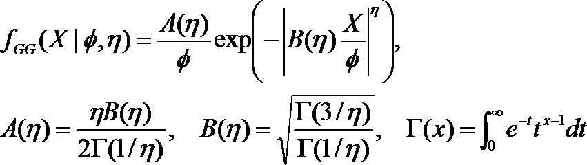

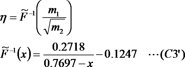

第二実施形態の復号装置及び方法は、第一実施形態と同様であるため重複説明を省略する。
線形予測分析部22及び非平滑化振幅スペクトル包絡系列生成部23を1つのスペクトル包絡推定部2Aとして捉えると、このスペクトル包絡推定部2Aは、時系列信号に対応する例えばMDCT係数列である周波数領域サンプル列の絶対値のη1乗をパワースペクトルと見做したスペクトル包絡(非平滑化振幅スペクトル包絡系列)の推定を行っていると言える。ここで、「パワースペクトルと見做した」とは、パワースペクトルを通常用いるところに、η1乗のスペクトルを用いることを意味する。
また、各装置又は各方法における各部をコンピュータによって実現してもよい。その場合、各装置又は各方法の処理内容はプログラムによって記述される。そして、このプログラムをコンピュータで実行することにより、各装置又は各方法における各部がコンピュータ上で実現される。
Claims (30)
- パラメータηを正の数として、時系列信号に対応するパラメータηを、その時系列信号に対応する周波数領域サンプル列の絶対値のη乗をパワースペクトルと見做すことにより推定されたスペクトル包絡で上記周波数領域サンプル列を除算した系列である白色化スペクトル系列のヒストグラムを近似する一般化ガウス分布の形状パラメータとし、η1はパラメータηの所定の値であるとして、
時系列信号に対応する周波数領域サンプル列の絶対値のη1乗をパワースペクトルと見做した逆フーリエ変換を行うことにより得られる疑似相関関数信号列を用いて線形予測分析を行い線形予測係数に変換可能な係数を得る線形予測分析部と、
N種類(Nは1以上の整数)のパラメータηのそれぞれに対応するN個の符号帳が記憶され、各符号帳にはそれぞれのパラメータηに対応する線形予測係数に変換可能な係数の候補が複数個格納された符号帳記憶部と、
上記符号帳記憶部に記憶された符号帳に格納された線形予測係数に変換可能な係数の複数個の候補と、上記線形予測分析部が得た線形予測係数に変換可能な係数と、のηの値を適合させる適合部と、
上記ηの値が適合された線形予測係数に変換可能な係数の複数個の候補と線形予測係数に変換可能な係数とを用いて、上記線形予測分析部が得た線形予測係数に変換可能な係数に対応する線形予測係数符号を得る符号化部と、
を含む線形予測符号化装置。 - 請求項1の線形予測符号化装置であって、
上記適合部は、上記符号帳記憶部に記憶された線形予測係数に変換可能な係数の候補に対して、η1に応じた第一線形変換を行い、第一線形変換後の線形予測係数に変換可能な係数の複数個の候補を得る線形変換部を含み、
上記符号化部は、上記線形予測分析部が得た線形予測係数に変換可能な係数と、上記適合部が得た上記第一線形変換後の線形予測係数に変換可能な係数の複数個の候補と、を用いて、上記線形予測分析部が得た線形予測係数に変換可能な係数に対応する線形予測係数符号を得る、
線形予測符号化装置。 - 請求項1の線形予測符号化装置であって、
上記適合部は、上記線形予測分析部が得た線形予測係数に変換可能な係数に対して、η1に応じた第二線形変換を行い、第二線形変換後の線形予測係数に変換可能な係数を得る線形変換部を含み、
上記符号化部は、上記適合部が得た上記第二線形変換後の線形予測係数に変換可能な係数と、上記符号帳に格納された線形予測係数に変換可能な係数の複数個の候補と、を用いて、上記線形予測分析部が得た線形予測係数に変換可能な係数に対応する線形予測係数符号を得る、
線形予測符号化装置。 - 請求項1の線形予測符号化装置であって、
η2,η3はパラメータηの所定の値であるとして、
上記符号帳記憶部には、η2に対応する符号帳が記憶されており、
上記適合部は、上記符号帳記憶部に記憶された線形予測係数に変換可能な係数の複数個の候補に対して、η3に応じた第一線形変換を行い、第一線形変換後の線形予測係数に変換可能な係数の複数個の候補を得、上記線形予測分析部が得た線形予測係数に変換可能な係数に対して、η3に応じた第二線形変換を行い、第二線形変換後の線形予測係数に変換可能な係数を得る、線形変換部であり、
上記符号化部は、上記適合部が得た上記第二線形変換後の線形予測係数に変換可能な係数と、上記適合部が得た上記第一線形変換後の線形予測係数に変換可能な係数の複数個の候補と、を用いて、上記線形予測分析部が得た線形予測係数に変換可能な係数に対応する線形予測係数符号を得る、
線形予測符号化装置。 - 請求項1の線形予測符号化装置であって、
η2はパラメータηの所定の値であるとして、
上記符号帳記憶部には、複数の符号帳が記憶されており、
上記適合部は、上記符号帳記憶部に記憶された複数の符号帳の中から上記η2に応じて符号帳を選択する符号帳選択部と、上記線形予測分析部で得られた線形予測係数に変換可能な係数に対する、η2に応じた第二線形変換を行う線形変換部とであり、
上記符号化部は、上記第二線形変換後の線形予測係数に変換可能な係数について、上記選択された符号帳を用いて符号化して線形予測係数符号を得る、
線形予測符号化装置。 - 請求項1の線形予測符号化装置であって、
η2はパラメータηの所定の値であるとして、
上記符号帳記憶部には、複数の符号帳が記憶されており、
上記適合部は、上記符号帳記憶部に記憶された複数の符号帳の中から上記η2に応じて符号帳を選択する符号帳選択部と、上記選択された符号帳に格納された線形予測係数に変換可能な係数の複数個の候補に対する、η1に応じた第一線形変換を行う線形変換部とであり、
上記符号化部は、上記線形予測分析部で得られた線形予測係数に変換可能な係数について、上記第一線形変換後の線形予測係数に変換可能な係数の候補を用いて符号化して線形予測係数符号を得る、
線形予測符号化装置。 - 請求項1の線形予測符号化装置であって、
η2,η3はパラメータηの所定の値であるとして、
上記符号帳記憶部には、複数の符号帳が記憶されており、
上記適合部は、上記符号帳記憶部に記憶された複数の符号帳の中から上記η3に応じて符号帳を選択する符号帳選択部と、上記選択された符号帳に格納された線形予測係数に変換可能な係数の複数個の候補に対する、η2に応じた第一線形変換を行うと共に、上記線形予測分析部で得られた線形予測係数に変換可能な係数に対する、η2に応じた第二線形変換を行う線形変換部とであり、
上記符号化部は、上記第二線形変換後の線形予測係数に変換可能な係数について、上記第一線形変換後の線形予測係数に変換可能な係数の候補を用いて符号化して線形予測係数符号を得る、
線形予測符号化装置。 - 請求項2の線形予測符号化装置において、
上記線形変換部は、上記η1が小さいほど上記第一線形変換後の線形予測係数に変換可能な係数の候補に対応する振幅スペクトル包絡の系列が平坦になるように上記第一線形変換を行う、
線形予測符号化装置。 - 請求項2から8の何れかの線形予測符号化装置において、
pを線形予測係数に変換可能な係数の次数とし、上記線形予測係数に変換可能な係数又は上記線形予測係数に変換可能な係数の候補を^ω[k][k=1,2,…,p]とし、上記第一線形変換後及び上記第二線形変換後の線形予測係数に変換可能な係数又は上記線形予測係数に変換可能な係数の候補を~ω[k][k=1,2,…,p]とし、x1,x2,…xp,y1,y2,…yp-1,z2,z3,…zpを所定の非負の数とし、y1,y2,…yp-1,z2,z3,…zpの少なくとも1つは所定の正の数であるとし、Kをx1,x2,…xp,y1,y2,…yp-1,z2,z3,…zp以外の要素が0である行列として、
上記線形変換部は、下記式により上記第一線形変換と上記第二線形変換との少なくとも一方を行う、
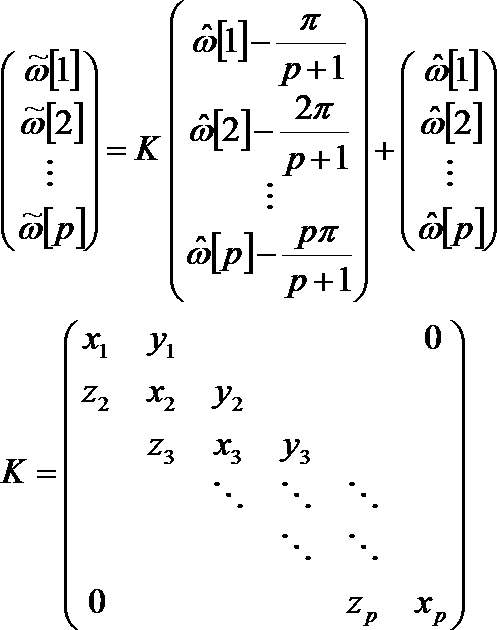
線形予測符号化装置。 - 請求項2の線形予測符号化装置において、
上記線形変換部は、上記η1が小さいほど上記第一線形変換後の線形予測係数に変換可能な係数の候補の次数が小さくなるように上記第一線形変換を行う、
線形予測符号化装置。 - 請求項1,2,3,4の何れかの線形予測符号化装置であって、
上記符号帳記憶部には、複数の符号帳が記憶されており、
上記適合部は、上記符号帳記憶部に記憶された複数の符号帳の中から上記η1に応じて符号帳を選択する符号帳選択部を含み、
上記符号化部は、上記線形予測分析部が得た線形予測係数に変換可能な係数と、上記適合部が得た線形予測係数に変換可能な係数の複数個の候補と、を用いて、上記線形予測分析部が得た上記線形予測係数に変換可能な係数に対応する線形予測係数符号を得る、
線形予測符号化装置 - 請求項11の線形予測符号化装置において、
上記符号帳記憶部には、線形予測係数に変換可能な係数の候補数が異なる複数の符号帳が記憶されており、
上記符号帳選択部は、上記η1が大きいほど、上記符号帳記憶部に記憶された複数の符号帳の中から、線形予測係数に変換可能な係数の候補数が多い符号帳を選択する、
線形予測符号化装置。 - 請求項11又は12の線形予測符号化装置において、
上記符号帳記憶部には、符号帳に記憶された線形予測係数に変換可能な係数の候補に対応する振幅スペクトル包絡の系列を1/η1乗した系列である非平滑化スペクトル包絡系列の平坦度合いが異なる複数の符号帳が記憶されており、
上記符号帳選択部は、上記η1が小さいほど、上記符号帳記憶部に記憶された複数の符号帳の中から、符号帳に記憶された線形予測係数に変換可能な係数の候補に対応する振幅スペクトル包絡の系列を1/η1乗した系列である非平滑化スペクトル包絡系列がより平坦である符号帳を選択する、
線形予測符号化装置。 - 請求項11又は12の線形予測符号化装置において、
上記符号帳記憶部には、線形予測係数に変換可能な係数の候補間の間隔が異なる複数の符号帳が記憶されており、
上記符号帳選択部は、上記ηが小さいほど、上記符号帳記憶部に記憶された複数の符号帳の中から、線形予測係数に変換可能な係数の候補間の間隔が狭い符号帳を選択する、
線形予測符号化装置。 - パラメータηを正の数として、時系列信号に対応するパラメータηを、その時系列信号に対応する周波数領域サンプル列の絶対値のη乗をパワースペクトルと見做すことにより推定されたスペクトル包絡で上記周波数領域サンプル列を除算した系列である白色化スペクトル系列のヒストグラムを近似する一般化ガウス分布の形状パラメータとし、η1はパラメータηの所定の値であるとして、
時系列信号に対応する周波数領域サンプル列の絶対値のη1乗をパワースペクトルと見做した逆フーリエ変換を行うことにより得られる疑似相関関数信号列を用いて線形予測分析を行い線形予測係数に変換可能な係数を得る線形予測分析部と、
符号帳が記憶された符号帳記憶部と、
入力されたη1に基づいて、上記符号帳記憶部に記憶された符号帳と上記線形予測係数に変換可能な係数との少なくとも一方を適合させる適合部と、
上記符号帳又は上記適合された符号帳を用いて、上記線形予測係数に変換可能な係数又は上記適合された線形予測係数に変換可能な係数を符号化する符号化部と、
を含む線形予測符号化装置。 - 符号帳が記憶された符号帳記憶部と、
η1を正の数として、入力されたη1に基づいて、上記符号帳記憶部に記憶された符号帳と、上記符号帳に格納された複数個の線形予測係数に変換可能な係数の候補のうち、入力された線形予測係数符号に対応する線形予測係数に変換可能な係数の候補との少なくとも一方を適合させる適合部を含み、
上記線形予測係数に変換可能な係数は、上記線形予測係数に変換可能な係数に対応する振幅スペクトル包絡の系列を1/η1乗した系列である非平滑化スペクトル包絡系列を得るために用いられる、
線形予測復号装置。 - 請求項16の線形予測復号装置であって、
上記符号帳に格納された複数個の線形予測係数に変換可能な係数の候補のうち、入力された線形予測係数符号に対応する線形予測係数に変換可能な係数の候補を線形予測係数に変換可能な係数として得る復号部を更に含み、
上記適合部は、上記復号部で得られた線形予測係数に変換可能な係数に対して、所定の正の数であるη1に応じた線形変換をして線形予測係数に変換可能な係数を得る線形変換部である、
線形予測復号装置。 - 請求項16の線形予測復号装置であって、
上記符号帳には、複数の符号帳が記憶されており、
η2を正の数として、上記適合部は、上記符号帳記憶部に記憶された複数の符号帳の中から上記η2に応じて符号帳を選択する符号帳選択部と、復号部で得られた線形予測係数に変換可能な係数に対して、所定の正の数であるη1に応じた線形変換をして線形予測係数に変換可能な係数を得る線形変換部とであり、
上記選択された符号帳に格納された複数個の線形予測係数に変換可能な係数の候補のうち、入力された線形予測係数符号に対応する線形予測係数に変換可能な係数の候補を線形予測係数に変換可能な係数として得る上記復号部を更に含む、
線形予測復号装置。 - 請求項17の線形予測復号装置において、
上記線形変換部は、上記η1が小さいほど上記線形変換部で得られた線形予測係数に変換可能な係数に対応する振幅スペクトル包絡の系列が平坦になるように上記線形変換を行う、
線形予測復号装置。 - 請求項17から19の何れかの線形予測復号装置において、
pを線形予測係数に変換可能な係数の次数とし、上記復号部で得られた線形予測係数に変換可能な係数を^ω[k][k=1,2,…,p]とし、上記線形変換後の線形予測係数に変換可能な係数を~ω[k][k=1,2,…,p]とし、x1,x2,…xp,y1,y2,…yp-1,z2,z3,…zpを所定の非負の数とし、y1,y2,…yp-1,z2,z3,…zpの少なくとも1つは所定の正の数であるとし、Kをx1,x2,…xp,y1,y2,…yp-1,z2,z3,…zp以外の要素が0である行列として、
上記線形変換部は、下記式により線形変換を行う、
線形予測復号装置。 - 請求項17の線形予測復号装置において、
上記線形変換部は、上記η1が小さいほど上記線形変換後の線形予測係数に変換可能な係数の次数が小さくなるように上記線形変換を行う、
線形予測復号装置。 - 請求項16の線形予測復号装置であって、
上記符号帳には、複数の符号帳が記憶されており、
上記適合部は、上記符号帳記憶部に記憶された複数の符号帳の中から上記η1に応じて符号帳を選択する符号帳選択部であり、上記選択された符号帳を用いて、入力された線形予測係数符号を復号して線形予測係数に変換可能な係数を得る復号部を更に含む
線形予測復号装置。 - 請求項22の線形予測復号装置において、
上記符号帳記憶部には、線形予測係数に変換可能な係数の候補数が異なる複数の符号帳が記憶されており、
上記符号帳選択部は、上記η1が大きいほど、上記符号帳記憶部に記憶された複数の符号帳の中から、線形予測係数に変換可能な係数の候補数が多い符号帳を選択する、
線形予測復号装置。 - 請求項22又は23の線形予測復号装置において、
上記符号帳記憶部には、符号帳に記憶された線形予測係数に変換可能な係数の候補に対応する振幅スペクトル包絡の系列を1/η1乗した系列である非平滑化スペクトル包絡系列の平坦度合いが異なる複数の符号帳が記憶されており、
上記符号帳選択部は、上記η1が小さいほど、上記符号帳記憶部に記憶された複数の符号帳の中から、符号帳に記憶された線形予測係数に変換可能な係数の候補に対応する振幅スペクトル包絡の系列を1/η1乗した系列である非平滑化スペクトル包絡系列が平坦である符号帳を選択する、
線形予測復号装置。 - 請求項22又は23の線形予測復号装置において、
上記符号帳記憶部には、線形予測係数に変換可能な係数の候補間の間隔が異なる複数の符号帳が記憶されており、
上記符号帳選択部は、上記η1が小さいほど、上記符号帳記憶部に記憶された複数の符号帳の中から、線形予測係数に変換可能な係数の候補間の間隔が狭い符号帳を選択する、
線形予測復号装置。 - パラメータηを正の数として、時系列信号に対応するパラメータηを、その時系列信号に対応する周波数領域サンプル列の絶対値のη乗をパワースペクトルと見做すことにより推定されたスペクトル包絡で上記周波数領域サンプル列を除算した系列である白色化スペクトル系列のヒストグラムを近似する一般化ガウス分布の形状パラメータとし、η1はパラメータηの所定の値であるとして、
線形予測分析部が、時系列信号に対応する周波数領域サンプル列の絶対値のη1乗をパワースペクトルと見做した逆フーリエ変換を行うことにより得られる疑似相関関数信号列を用いて線形予測分析を行い線形予測係数に変換可能な係数を得る線形予測分析ステップと、
適合部が、N種類(Nは1以上の整数)のパラメータηのそれぞれに対応するN個の符号帳が記憶され、各符号帳にはそれぞれのパラメータηに対応する線形予測係数に変換可能な係数の候補が複数個格納された符号帳記憶部に記憶された符号帳に格納された線形予測係数に変換可能な係数の複数個の候補と、上記線形予測分析ステップが得た線形予測係数に変換可能な係数と、のηの値を適合させる適合ステップと、
符号化部が、上記ηの値が適合された線形予測係数に変換可能な係数の複数個の候補と線形予測係数に変換可能な係数とを用いて、上記線形予測分析部が得た線形予測係数に変換可能な係数に対応する線形予測係数符号を得る符号化ステップと、
を含む線形予測符号化方法。 - パラメータηを正の数として、時系列信号に対応するパラメータηを、その時系列信号に対応する周波数領域サンプル列の絶対値のη乗をパワースペクトルと見做すことにより推定されたスペクトル包絡で上記周波数領域サンプル列を除算した系列である白色化スペクトル系列のヒストグラムを近似する一般化ガウス分布の形状パラメータとし、η1はパラメータηの所定の値であるとして、
時系列信号に対応する周波数領域サンプル列の絶対値のη1乗をパワースペクトルと見做した逆フーリエ変換を行うことにより得られる疑似相関関数信号列を用いて線形予測分析を行い線形予測係数に変換可能な係数を得る線形予測分析ステップ、
入力されたη1に基づいて、符号帳記憶部に記憶された符号帳と上記線形予測係数に変換可能な係数との少なくとも一方を適合させる適合ステップと、
上記符号帳又は上記適合された符号帳を用いて、上記線形予測係数に変換可能な係数又は上記適合された線形予測係数に変換可能な係数を符号化する符号化ステップと、
を含む線形予測符号化方法。 - η1を正の数として、入力されたη1に基づいて、符号帳記憶部に記憶された符号帳と、上記符号帳に格納された複数個の線形予測係数に変換可能な係数の候補のうち、入力された線形予測係数符号に対応する線形予測係数に変換可能な係数の候補との少なくとも一方を適合させる適合ステップを含み、
上記線形予測係数に変換可能な係数は、上記線形予測係数に変換可能な係数に対応する振幅スペクトル包絡の系列を1/η1乗した系列である非平滑化スペクトル包絡系列を得るために用いられる、
線形予測復号方法。 - 請求項1から15の何れかの線形予測符号化装置又は請求項16から25の何れかの線形予測復号装置の各部としてコンピュータを機能させるためのプログラム。
- 請求項1から15の何れかの線形予測符号化装置又は請求項16から25の何れかの線形予測復号装置の各部としてコンピュータを機能させるためのプログラムが記録されたコンピュータ読み取り可能な記録媒体。
Priority Applications (5)
| Application Number | Priority Date | Filing Date | Title |
|---|---|---|---|
| US15/562,689 US10325609B2 (en) | 2015-04-13 | 2016-04-11 | Coding and decoding a sound signal by adapting coefficients transformable to linear predictive coefficients and/or adapting a code book |
| KR1020177028710A KR102061300B1 (ko) | 2015-04-13 | 2016-04-11 | 선형 예측 부호화 장치, 선형 예측 복호 장치, 이들의 방법, 프로그램 및 기록 매체 |
| EP16780006.9A EP3270376B1 (en) | 2015-04-13 | 2016-04-11 | Sound signal linear predictive coding |
| JP2017512523A JP6517924B2 (ja) | 2015-04-13 | 2016-04-11 | 線形予測符号化装置、方法、プログラム及び記録媒体 |
| CN201680021332.5A CN107408390B (zh) | 2015-04-13 | 2016-04-11 | 线性预测编码装置、线性预测解码装置、它们的方法以及记录介质 |
Applications Claiming Priority (4)
| Application Number | Priority Date | Filing Date | Title |
|---|---|---|---|
| JP2015-081747 | 2015-04-13 | ||
| JP2015081747 | 2015-04-13 | ||
| JP2015081746 | 2015-04-13 | ||
| JP2015-081746 | 2015-04-13 |
Publications (1)
| Publication Number | Publication Date |
|---|---|
| WO2016167215A1 true WO2016167215A1 (ja) | 2016-10-20 |
Family
ID=57126589
Family Applications (1)
| Application Number | Title | Priority Date | Filing Date |
|---|---|---|---|
| PCT/JP2016/061682 Ceased WO2016167215A1 (ja) | 2015-04-13 | 2016-04-11 | 線形予測符号化装置、線形予測復号装置、これらの方法、プログラム及び記録媒体 |
Country Status (6)
| Country | Link |
|---|---|
| US (1) | US10325609B2 (ja) |
| EP (1) | EP3270376B1 (ja) |
| JP (2) | JP6517924B2 (ja) |
| KR (1) | KR102061300B1 (ja) |
| CN (1) | CN107408390B (ja) |
| WO (1) | WO2016167215A1 (ja) |
Families Citing this family (6)
| Publication number | Priority date | Publication date | Assignee | Title |
|---|---|---|---|---|
| JP6387117B2 (ja) * | 2015-01-30 | 2018-09-05 | 日本電信電話株式会社 | 符号化装置、復号装置、これらの方法、プログラム及び記録媒体 |
| JP6499206B2 (ja) * | 2015-01-30 | 2019-04-10 | 日本電信電話株式会社 | パラメータ決定装置、方法、プログラム及び記録媒体 |
| CN112350760B (zh) * | 2019-08-09 | 2021-07-23 | 大唐移动通信设备有限公司 | 一种预编码码本选择的方法及装置 |
| KR20210133554A (ko) * | 2020-04-29 | 2021-11-08 | 한국전자통신연구원 | 선형 예측 코딩을 이용한 오디오 신호의 부호화 및 복호화 방법과 이를 수행하는 부호화기 및 복호화기 |
| CN111901004B (zh) * | 2020-08-04 | 2022-04-12 | 三维通信股份有限公司 | 平坦度的补偿方法和装置、存储介质和电子设备 |
| US12525248B2 (en) * | 2022-08-11 | 2026-01-13 | Electronics And Telecommunications Research Institute | Apparatus for encoding and decoding audio signal and method of operation thereof |
Citations (1)
| Publication number | Priority date | Publication date | Assignee | Title |
|---|---|---|---|---|
| WO2013176177A1 (ja) * | 2012-05-23 | 2013-11-28 | 日本電信電話株式会社 | 符号化方法、復号方法、符号化装置、復号装置、プログラム、および記録媒体 |
Family Cites Families (25)
| Publication number | Priority date | Publication date | Assignee | Title |
|---|---|---|---|---|
| JPS6253028A (ja) | 1985-09-02 | 1987-03-07 | Nec Corp | 適応形符号化復号化方式とその装置 |
| JP3186013B2 (ja) * | 1995-01-13 | 2001-07-11 | 日本電信電話株式会社 | 音響信号変換符号化方法及びその復号化方法 |
| GB2326572A (en) * | 1997-06-19 | 1998-12-23 | Softsound Limited | Low bit rate audio coder and decoder |
| US6453289B1 (en) * | 1998-07-24 | 2002-09-17 | Hughes Electronics Corporation | Method of noise reduction for speech codecs |
| CA2733453C (en) * | 2000-11-30 | 2014-10-14 | Panasonic Corporation | Lpc vector quantization apparatus |
| JP4365610B2 (ja) * | 2003-03-31 | 2009-11-18 | パナソニック株式会社 | 音声復号化装置および音声復号化方法 |
| CN101556800B (zh) * | 2003-10-23 | 2012-05-23 | 松下电器产业株式会社 | 音频频谱编解码方法和装置、声音信号发送和接收装置 |
| JP4493030B2 (ja) * | 2005-10-12 | 2010-06-30 | 月島機械株式会社 | ろ過装置 |
| EP1988544B1 (en) | 2006-03-10 | 2014-12-24 | Panasonic Intellectual Property Corporation of America | Coding device and coding method |
| ATE518224T1 (de) * | 2008-01-04 | 2011-08-15 | Dolby Int Ab | Audiokodierer und -dekodierer |
| CN102449689B (zh) * | 2009-06-03 | 2014-08-06 | 日本电信电话株式会社 | 编码方法、编码装置、编码程序、以及它们的记录介质 |
| RU2510974C2 (ru) * | 2010-01-08 | 2014-04-10 | Ниппон Телеграф Энд Телефон Корпорейшн | Способ кодирования, способ декодирования, устройство кодера, устройство декодера, программа и носитель записи |
| JP5602769B2 (ja) * | 2010-01-14 | 2014-10-08 | パナソニック インテレクチュアル プロパティ コーポレーション オブ アメリカ | 符号化装置、復号装置、符号化方法及び復号方法 |
| FR2961937A1 (fr) * | 2010-06-29 | 2011-12-30 | France Telecom | Codage/decodage predictif lineaire adaptatif |
| JP2012163919A (ja) * | 2011-02-09 | 2012-08-30 | Sony Corp | 音声信号処理装置、および音声信号処理方法、並びにプログラム |
| CN103620675B (zh) * | 2011-04-21 | 2015-12-23 | 三星电子株式会社 | 对线性预测编码系数进行量化的设备、声音编码设备、对线性预测编码系数进行反量化的设备、声音解码设备及其电子装置 |
| JP5958866B2 (ja) * | 2012-08-01 | 2016-08-02 | 国立研究開発法人産業技術総合研究所 | 音声分析合成のためのスペクトル包絡及び群遅延の推定システム及び音声信号の合成システム |
| PL3525208T3 (pl) * | 2012-10-01 | 2021-12-13 | Nippon Telegraph And Telephone Corporation | Sposób kodowania, koder, program i nośnik zapisu |
| FR3011408A1 (fr) * | 2013-09-30 | 2015-04-03 | Orange | Re-echantillonnage d'un signal audio pour un codage/decodage a bas retard |
| CN103824561B (zh) * | 2014-02-18 | 2015-03-11 | 北京邮电大学 | 一种语音线性预测编码模型的缺失值非线性估算方法 |
| WO2015162979A1 (ja) * | 2014-04-24 | 2015-10-29 | 日本電信電話株式会社 | 周波数領域パラメータ列生成方法、符号化方法、復号方法、周波数領域パラメータ列生成装置、符号化装置、復号装置、プログラム及び記録媒体 |
| EP3226243B1 (en) * | 2014-11-27 | 2022-01-05 | Nippon Telegraph and Telephone Corporation | Encoding apparatus, decoding apparatus, and method and program for the same |
| JP6499206B2 (ja) * | 2015-01-30 | 2019-04-10 | 日本電信電話株式会社 | パラメータ決定装置、方法、プログラム及び記録媒体 |
| JP6387117B2 (ja) * | 2015-01-30 | 2018-09-05 | 日本電信電話株式会社 | 符号化装置、復号装置、これらの方法、プログラム及び記録媒体 |
| CN107851442B (zh) * | 2015-04-13 | 2021-07-20 | 日本电信电话株式会社 | 匹配装置、判定装置、它们的方法、程序及记录介质 |
-
2016
- 2016-04-11 WO PCT/JP2016/061682 patent/WO2016167215A1/ja not_active Ceased
- 2016-04-11 CN CN201680021332.5A patent/CN107408390B/zh active Active
- 2016-04-11 JP JP2017512523A patent/JP6517924B2/ja active Active
- 2016-04-11 US US15/562,689 patent/US10325609B2/en active Active
- 2016-04-11 KR KR1020177028710A patent/KR102061300B1/ko active Active
- 2016-04-11 EP EP16780006.9A patent/EP3270376B1/en active Active
-
2019
- 2019-01-23 JP JP2019009389A patent/JP6633787B2/ja active Active
Patent Citations (1)
| Publication number | Priority date | Publication date | Assignee | Title |
|---|---|---|---|---|
| WO2013176177A1 (ja) * | 2012-05-23 | 2013-11-28 | 日本電信電話株式会社 | 符号化方法、復号方法、符号化装置、復号装置、プログラム、および記録媒体 |
Non-Patent Citations (2)
| Title |
|---|
| JUHA OJANPERA ET AL.: "Long Term Predictor for Transform Domain Perceptual Audio Coding", PROC. 107TH CONVENTION OF AES, 24 September 1999 (1999-09-24), pages 1 - 25 * |
| See also references of EP3270376A4 * |
Also Published As
| Publication number | Publication date |
|---|---|
| JP2019079069A (ja) | 2019-05-23 |
| CN107408390B (zh) | 2021-08-06 |
| JPWO2016167215A1 (ja) | 2018-02-01 |
| KR102061300B1 (ko) | 2020-02-11 |
| EP3270376A1 (en) | 2018-01-17 |
| US10325609B2 (en) | 2019-06-18 |
| US20180096694A1 (en) | 2018-04-05 |
| CN107408390A (zh) | 2017-11-28 |
| EP3270376A4 (en) | 2018-08-29 |
| JP6517924B2 (ja) | 2019-05-22 |
| KR20170127533A (ko) | 2017-11-21 |
| EP3270376B1 (en) | 2020-03-18 |
| JP6633787B2 (ja) | 2020-01-22 |
Similar Documents
| Publication | Publication Date | Title |
|---|---|---|
| JP6633787B2 (ja) | 線形予測復号装置、方法、プログラム及び記録媒体 | |
| JP6422813B2 (ja) | 符号化装置、復号装置、これらの方法及びプログラム | |
| JP6484358B2 (ja) | 符号化装置、及びその方法、プログラム、記録媒体 | |
| JP6457552B2 (ja) | 符号化装置、復号装置、これらの方法及びプログラム | |
| JP6499206B2 (ja) | パラメータ決定装置、方法、プログラム及び記録媒体 | |
| JP6387117B2 (ja) | 符号化装置、復号装置、これらの方法、プログラム及び記録媒体 | |
| CN106233383B (zh) | 频域参数串生成方法、频域参数串生成装置以及记录介质 | |
| CN110534122B (zh) | 解码装置、及其方法、记录介质 |
Legal Events
| Date | Code | Title | Description |
|---|---|---|---|
| 121 | Ep: the epo has been informed by wipo that ep was designated in this application |
Ref document number: 16780006 Country of ref document: EP Kind code of ref document: A1 |
|
| WWE | Wipo information: entry into national phase |
Ref document number: 15562689 Country of ref document: US |
|
| ENP | Entry into the national phase |
Ref document number: 2017512523 Country of ref document: JP Kind code of ref document: A |
|
| ENP | Entry into the national phase |
Ref document number: 20177028710 Country of ref document: KR Kind code of ref document: A |
|
| REEP | Request for entry into the european phase |
Ref document number: 2016780006 Country of ref document: EP |
|
| NENP | Non-entry into the national phase |
Ref country code: DE |