WO2016170802A1 - クランプ装置 - Google Patents
クランプ装置 Download PDFInfo
- Publication number
- WO2016170802A1 WO2016170802A1 PCT/JP2016/050108 JP2016050108W WO2016170802A1 WO 2016170802 A1 WO2016170802 A1 WO 2016170802A1 JP 2016050108 W JP2016050108 W JP 2016050108W WO 2016170802 A1 WO2016170802 A1 WO 2016170802A1
- Authority
- WO
- WIPO (PCT)
- Prior art keywords
- clamp
- hole
- clamping device
- clamp arms
- pair
- Prior art date
- Legal status (The legal status is an assumption and is not a legal conclusion. Google has not performed a legal analysis and makes no representation as to the accuracy of the status listed.)
- Ceased
Links
Images



Classifications
-
- B—PERFORMING OPERATIONS; TRANSPORTING
- B25—HAND TOOLS; PORTABLE POWER-DRIVEN TOOLS; MANIPULATORS
- B25B—TOOLS OR BENCH DEVICES NOT OTHERWISE PROVIDED FOR, FOR FASTENING, CONNECTING, DISENGAGING OR HOLDING
- B25B5/00—Clamps
- B25B5/06—Arrangements for positively actuating jaws
- B25B5/061—Arrangements for positively actuating jaws with fluid drive
- B25B5/064—Arrangements for positively actuating jaws with fluid drive with clamping means pivoting around an axis perpendicular to the pressing direction
-
- B—PERFORMING OPERATIONS; TRANSPORTING
- B23—MACHINE TOOLS; METAL-WORKING NOT OTHERWISE PROVIDED FOR
- B23Q—DETAILS, COMPONENTS, OR ACCESSORIES FOR MACHINE TOOLS, e.g. ARRANGEMENTS FOR COPYING OR CONTROLLING; MACHINE TOOLS IN GENERAL CHARACTERISED BY THE CONSTRUCTION OF PARTICULAR DETAILS OR COMPONENTS; COMBINATIONS OR ASSOCIATIONS OF METAL-WORKING MACHINES, NOT DIRECTED TO A PARTICULAR RESULT
- B23Q3/00—Devices holding, supporting, or positioning work or tools, of a kind normally removable from the machine
- B23Q3/02—Devices holding, supporting, or positioning work or tools, of a kind normally removable from the machine for mounting on a work-table, tool-slide, or analogous part
- B23Q3/06—Work-clamping means
-
- B—PERFORMING OPERATIONS; TRANSPORTING
- B25—HAND TOOLS; PORTABLE POWER-DRIVEN TOOLS; MANIPULATORS
- B25B—TOOLS OR BENCH DEVICES NOT OTHERWISE PROVIDED FOR, FOR FASTENING, CONNECTING, DISENGAGING OR HOLDING
- B25B5/00—Clamps
- B25B5/06—Arrangements for positively actuating jaws
- B25B5/08—Arrangements for positively actuating jaws using cams
- B25B5/087—Arrangements for positively actuating jaws using cams actuated by a hydraulic or pneumatic piston
Definitions
- the present invention relates to a clamp device that clamps a workpiece between a plurality of clamp arms.
- the clamping device is widely used in the welding process of automatic assembly lines in the machine industry and the like.
- this type of clamping device includes a pair of clamp arms that are rotatably provided to a clamp body via pins. Then, by applying the driving force of the cylinder to one end of each clamp arm, the clamp arm is rotated around the pin, and the workpiece is clamped from both the left and right sides by the gripping surface provided at the other end of the clamp arm. Then, after positioning, it is used for a required processing or a conveyance process (for example, refer patent 4950123).
- Japanese Patent Application Laid-Open No. 2015-37829 selectively selects a pair of clamp arms with attachments attached to the gripping surface and a pair of clamp arms without attachments attached to the gripping surface.
- a pivoting clamping device is disclosed.
- Japanese Patent Application Laid-Open No. 2009-12138 discloses a clamp device that clamps a workpiece by translating a pair of clamp arms in directions close to or away from each other.
- the distance between the gripping surfaces (hereinafter referred to as the clamp interval) at a clamping position where the gripping surfaces of the pair of clamp arms are parallel to each other is constant. Therefore, when the clamp interval and workpiece width dimension (interval between the parts contacting the gripping surface of each clamp arm in the workpiece) are different, an equal clamping force is applied to multiple types of workpieces having different width dimensions. However, it is not easy to clamp such a plurality of types of workpieces with certainty.
- the maximum opening angle of the other ends (grip surfaces) of the pair of clamp arms is such that the one ends of the pair of clamp arms do not interfere with each other. It will be restricted. That is, the distance between the pair of gripping surfaces in the unclamped state is relatively narrow. In this case, since it is necessary to avoid contact between the workpiece and the clamp arm, the supply direction and discharge direction of the workpiece with respect to the clamp device may be limited.
- the present invention has been made in consideration of such problems, and can reliably and stably clamp a plurality of types of workpieces having different width dimensions while suppressing an increase in size of the apparatus with a simple configuration.
- An object of the present invention is to provide a clamping device capable of increasing the degree of freedom in the workpiece supply direction and the discharge direction.
- a clamp device is a clamp device that clamps a workpiece between a plurality of clamp arms, and includes a clamp body, a plurality of clamp arms supported to be movable with respect to the clamp body, and a linear reciprocating motion.
- a driving unit provided on the clamp body with a displacement body that transmits the driving force, and a driving force transmission mechanism that transmits a driving force of the driving unit to each of the clamp arms, the driving force transmission mechanism including the displacement A plurality of clamp arms that rotate while moving in a direction in which the plurality of clamp arms move toward and away from each other;
- the clamp arm is converted into a second operation in which the clamp arm moves in a direction to approach and separate from each other.
- the clamp interval can be changed, it is possible to reliably and stably clamp a plurality of types of workpieces having different width dimensions while suppressing an increase in size of the clamp device with a simple configuration.
- the clamp arm can be rotated and the distance between the gripping surfaces in the unclamped state can be made relatively wide, the degree of freedom in the workpiece supply direction and the discharge direction can be increased.
- the driving force transmission mechanism includes a movable part provided in the displacement body and having a first cam hole formed therein, and a fixed part provided in the clamp body and having a second cam hole formed therein.
- fixed part may be arrange
- the movable portion moves linearly with respect to the clamp body as the displacement body moves linearly, whereby the first roller moves in the first cam hole and the second and third rollers. Moves in the second cam hole, so that the linear motion of the displacement body can be converted into the first motion and the second motion with a simple configuration.
- a plurality of the clamp arms are provided in a pair, the first cam holes are provided in a pair substantially symmetrically, and the second cam holes are provided in a pair substantially symmetrically.
- the one cam hole includes a first hole portion extending so as to incline toward one side of the moving direction of the movable portion in a direction in which the first symmetry axis of the pair of first cam holes is located, A second hole extending so as to incline in a direction in which the first symmetry axis is located from one hole toward one side of the moving direction of the movable part, and each second cam hole Is a third hole extending so as to incline toward one side of the moving direction of the movable part toward the direction in which the second symmetry axis of the pair of second cam holes is located, and the third hole And a fourth hole extending along the direction in which the second axis of symmetry is located.
- the first roller moves in the first hole to cause each clamp arm to perform a first operation
- the first roller moves in the second hole to cause each clamp arm to perform a second operation.
- the second hole portion is inclined in the direction in which the first axis of symmetry is located with respect to the moving direction of the movable portion
- the first roller moves in the second hole portion to one side in the moving direction of the movable portion.
- the clamping force on the workpiece can be increased by the wedge action at the inclined surface angle ( ⁇ ).
- first axis and the second axis may be provided at an end portion of each clamp arm opposite to the side where the gripping surface is located.
- a pair of the movable portion, the fixed portion, the first roller, the second roller, and the third roller may be disposed on both sides of the clamp arm.
- the first operation and the second operation of the pair of clamp arms can be performed smoothly and stably.
- the movable portion may be provided with a slide portion
- the clamp body may be provided with a guide portion that guides the slide portion along the moving direction of the displacement body.
- the movable part can be smoothly linearly moved, the first operation and the second operation of the pair of clamp arms can be performed more smoothly and stably.
- the apparatus further includes a work placement portion on which the work is placed so that each clamp arm does not protrude toward the side where the work is located from the work placement surface of the work placement portion in an unclamped state. It may be arranged.
- the present invention it is possible to reliably and stably clamp a plurality of types of workpieces having different width dimensions while suppressing an increase in the size of the apparatus with a simple configuration, and the degree of freedom in the supply direction and the discharge direction of the workpiece. Can be increased.
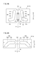
- FIG. 4A is a plan view of the movable plate
- FIG. 4B is a plan view of the fixed plate.
- FIG. 4A is a plan view of the movable plate
- FIG. 4B is a plan view of the fixed plate.
- FIG. 4A is a plan view of the movable plate
- FIG. 4B is a plan view of the fixed plate.
- FIG. 4A is a plan view of the movable plate
- FIG. 4B is a plan view of the fixed plate.
- FIG. 4A is a partially omitted cross-sectional front view showing an unclamped state of the clamp device.
- It is a partially-omitted cross-sectional front view showing the maximum clamp interval of the clamp device.
- FIG. 8 is a partially omitted cross-sectional front view illustrating a state in which a workpiece having a width dimension different from the width dimension of the workpiece illustrated in FIG. 7 is clamped.
- the clamp device 10 clamps the workpieces W1 and W2 between a pair (a plurality) of clamp arms 16a and 16b, and is applied to, for example, a welding process of an automatic assembly line in the machine industry or the like. Is done.
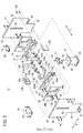
- the clamp device 10 includes a clamp body 12, a drive unit 14 provided on the clamp body 12, and a pair of left and right clamp arms 16 a provided movably with respect to the clamp body 12. 16b and a driving force transmission mechanism 18 for transmitting the driving force of the driving unit 14 to the clamp arms 16a and 16b.
- the width direction of the clamp device 10 (the arrangement direction of the clamp arms 16a and 16b) is the X direction
- the direction perpendicular to the X direction and the longitudinal direction of the clamp device 10 is the Y direction
- the X direction and the Y direction are taken as the Z direction.
- the lower direction in FIG. 1 is the Y1 direction
- the upper direction in FIG. 1 is the Y2 direction.
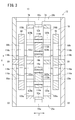
- the clamp body 12 includes a pair of T-shaped plate bodies 20 and 22 disposed substantially parallel to each other at a predetermined distance from each other, and a base portion 24 that connects the narrow end portions of the plate bodies 20 and 22 to each other. And a pair of left and right connecting portions 26a and 26b that connect the side portions of the plate bodies 20 and 22, and a work placement portion 28 that connects the other wide end portions of the plate bodies 20 and 22.
- Long holes (guide portions) 30 and 32 are formed along the longitudinal direction (Y direction) at substantially the center in the width direction (X direction) of the plate bodies 20 and 22.
- the base portion 24 is formed in a flat plate shape, and one side surface thereof is fastened by a screw 36 at the center in the width direction of the narrow portion 34 of the plate body 20, and the other side surface is a narrow portion of the plate body 22. 38 is fastened by a screw 40 at substantially the center in the width direction.
- the base part 24 is fixed to a floor surface etc. with the volt
- Each of the connecting portions 26 a and 26 b has one side surface fastened by a screw 44 at the center in the Y direction of the wide portion 42 of the plate body 20, and the other side surface at the center in the Y direction of the wide portion 46 of the plate body 22. Fastened with screws 48. That is, the connecting portion 26a and the connecting portion 26b are opposed to each other in the X direction.
- the entire inner surface of the connecting portion 26 a (the surface facing the connecting portion 26 b) has a full center in the Y direction at the approximate center in the direction in which the pair of plate bodies 20 and 22 are arranged (Z direction).
- a protruding portion 50a is formed.
- An inclined surface 52a that is inclined toward the outer surface side of the connecting portion 26a toward the Y2 direction is formed at the end portion in the Y2 direction of the tip surface of the protruding portion 50a.
- the connecting portion 26b is configured in the same manner as the connecting portion 26a, and a protruding portion 50b and an inclined surface 52b are formed.
- the workpiece placement portion 28 is a flat plate member on which the workpiece W ⁇ b> 1 is placed, and is fastened by a screw 54 at the approximate center of the wide portions 42 and 46 in the X direction.
- the drive unit 14 is configured as a fluid pressure cylinder (actuator). As shown in FIG. 5, the drive unit 14 is displaceable along the axial direction in the cylinder tube 56, an end block 58 that closes the opening on one end side (Y1 direction) of the cylinder tube 56, and the cylinder tube 56.
- a cover 64 the structure of the drive part 14 is not specifically limited, You may apply the various mechanism which can displace a displacement body linearly.
- a linear electric actuator including a ball screw actuator or the like can be employed as the drive unit.
- the cylinder tube 56 is disposed between the narrow portions 34 and 38 of the pair of plate bodies 20 and 22 (see FIG. 1).
- the cylinder tube 56 is formed with a first port and a second port (not shown) for supplying and discharging a compressed fluid (driving fluid).
- the pair of clamp arms 16a and 16b are located between the pair of connecting portions 26a and 26b and are spaced apart from each other along the X direction.
- the clamp arm 16a is formed in a quadrangular prism shape, and one end thereof bulges on both sides in the X direction.
- a gripping surface 66a that contacts the workpieces W1 and W2 is formed at the other end of the clamp arm 16a.
- the clamp arm 16b is configured similarly to the clamp arm 16a, and a gripping surface 66b is formed at the other end.
- the driving force transmission mechanism 18 includes a pair of movable plates (movable portions) 68 and 70 that are spaced apart from each other in the Z direction, and a Y1 direction of the pair of movable plates 68 and 70 in a state of being connected to the piston rod 62.
- a first connecting portion 72 that connects the end portions of the pair of movable plates 68, 70
- a second connecting portion 74 that connects end portions of the pair of movable plates 68, 70 in the Y2 direction, and a Z direction inside the pair of movable plates 68, 70.
- a pair of fixing plates (fixing portions) 76 and 78 that are spaced apart from each other.
- the movable plate 68 and the fixed plate 76 are disposed between the pair of clamp arms 16 a and 16 b and the wide portion 42, and the movable plate 70 and the fixed plate 78 are formed between the pair of clamp arms 16 a and 16 b and the wide portion 46. It is arranged in between.
- the movable plates 68 and 70 and the fixed plates 76 and 78 extend along the X direction in a state parallel to the wide portions 42 and 46.
- the movable plate 68 is configured in the same manner as the movable plate 70
- the fixed plate 76 is configured in the same manner as the fixed plate 78. Therefore, hereinafter, the configuration of the movable plate 68 and the fixed plate 76 will be described, and the description of the configuration of the movable plate 70 and the fixed plate 78 will be omitted.
- a concave first arrangement portion 80 in which the first connection portion 72 is arranged and a concave second arrangement portion 82 in which the second connection portion 74 is arranged are formed at the approximate center in the X direction of the movable plate 68. Yes.
- a slide portion 84 extending along the Y direction is fastened by a screw 86 to the surface of the movable plate 68 that faces the wide portion 42.
- the slide portion 84 is disposed in the long hole 30 of the plate body 20 so as to be slidable along the Y direction. Thereby, the movable plate 68 can be smoothly slid along the X direction under the guiding action of the long hole 30 of the plate body 20.
- the movable plate 68 is formed with a pair of first cam holes 88a and 88b formed substantially symmetrically with respect to the center line (first symmetry axis) CL1 in the X direction.
- the first cam hole 88a has an end portion 91a in the vicinity of the outer corner portion of the movable plate 68 in the Y1 direction, and is inclined in the Y2 direction from the end portion 91a toward the inner side in the X direction (center line CL1 side).
- a first hole 90a extending in the X direction and a second hole 92a extending so as to incline in the X direction toward the Y2 direction from the innermost position in the X direction in the first hole 90a. Yes.
- the first hole 90a is formed shorter than the second hole 92a.
- the inner surface 93a outside the second hole portion 92a is inclined at a predetermined inclined surface angle ⁇ with respect to the imaginary line IL in the Y direction, and functions as a wedge action surface that guides the first roller 116a described later.
- the first cam hole 88b is configured similarly to the first cam hole 88a, and includes a first hole 90b having an end 91b and a second hole 92b having an inner surface 93b.
- the first connecting portion 72 is a flat plate-like member extending in the Z direction, and the piston rod 62 is fastened by a screw 94 substantially at the center in the Z direction. Both end portions of the first connection portion 72 are formed to be narrower than the central portion thereof, and are fastened by screws 96 in a state where the first connection portion 72 is disposed in the first arrangement portion 80 of each movable plate 68, 70.
- the second connection portion 74 is a flat plate member extending along the Z direction. Both end portions of the second connection portion 74 are formed narrower than the central portion thereof, and are fastened by screws 98 in a state where the second connection portions 74 are arranged in the second arrangement portions 82 of the movable plates 68 and 70.
- the fixing plates 76 and 78 are fixed to the clamp body 12 by fastening both ends in the X direction to the protrusions 50a and 50b with screws 100.
- a first recessed portion 102 into which the first connecting portion 72 can be inserted and a second recessed portion 104 into which the second connecting portion 74 can be inserted are formed at approximately the center in the X direction of the fixing plates 76 and 78.
- the fixed plate 76 is formed with a pair of second cam holes 106a and 106b formed substantially symmetrically with respect to the center line (second symmetry axis) CL2 in the X direction.
- the second cam hole 106a is formed so that a part thereof overlaps a part of the first cam hole 88a in a plan view (front view) from the Z direction (see FIGS. 5 to 7). The same applies to the second cam hole 106b.
- the second cam hole 106a includes a third hole 108a extending from the vicinity of the outer corner of the fixing plate 76 in the Y1 direction so as to incline in the Y2 direction toward the inner side in the X direction (center line CL2 side), And a fourth hole 110a extending along the X direction from the innermost position in the X direction in the three holes 108a.
- the third hole 108a is set to have substantially the same length as the fourth hole 110a.
- the 2nd cam hole 106b is comprised similarly to the 2nd cam hole 106a, and has the 3rd hole part 108b and the 4th hole part 110b.
- the driving force transmission mechanism 18 includes a first shaft 112a and a second shaft 114a provided (fixed) at one end of the clamp arm 16a so as to penetrate in the Z direction, A first roller 116a that is rotatably provided on the single shaft 112a and moves in the first cam holes 88a and 88b of the movable plates 68 and 70, and a fixed roller 76 and 78 that is rotatably provided on the first shaft 112a.
- a second roller 118a that moves in the second cam hole 106a and a third roller 120a that is rotatably provided on the second shaft 114a and moves in the second cam hole 106a of the fixing plates 76 and 78 are provided. Yes.
- the first shaft 112a is located on the inner side in the X direction (the side on which the clamp arm 16b is located) than the second shaft 114a and extends longer than the second shaft 114a.
- the first shaft 112a extends to both sides in the Z direction while being provided at one end of the clamp arm 16a, and a first roller 116a and a second roller 118a are provided at each of the extended portions on both sides. ing.
- the second shaft 114a extends to both sides in the Z direction in a state of being provided at one end of the clamp arm 16b, and a third roller 120a is provided at each of the portions extending to both sides of the second shaft 114a.
- the first shaft 112a and the second shaft 114a are provided with a holding member 122a (see FIG. 3) for holding the positions of the first to third rollers 116a, 118a, and 120a in the axial direction.
- the driving force transmission mechanism 18 is rotatably provided to the first shaft 112b and the first shaft 112b and the second shaft 114b provided (fixed) so as to penetrate in one end portion of the clamp arm 16b in the Z direction.
- a first roller 116b that is provided and moves in the first cam hole 88b of the movable plates 68 and 70, and is rotatably provided on the first shaft 112b and moves in the second cam hole 106b of the fixed plates 76 and 78.
- a second roller 118b and a third roller 120b that is rotatably provided on the second shaft 114b and moves in the second cam holes 106b of the fixing plates 76 and 78 are provided.
- first shaft 112b, the second shaft 114b, and the first to third rollers 116b, 118b, and 120b have the same configuration as that provided on the clamp arm 16a side, description thereof is omitted.
- the holding member 122b (refer FIG. 3) is provided in the 1st axis
- the clamp device 10 is basically configured as described above, and the operation and effects thereof will be described next.
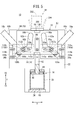
- the unclamped state in which the gripping surfaces 66a and 66b of the pair of clamp arms 16a and 16b shown in FIG.
- the first rollers 116a and 116b are located on the outermost side in the X direction in the first holes 90a and 90b.
- the second rollers 118a and 118b are located at the boundary between the third holes 108a and 108b and the fourth holes 110a and 110b, and the third rollers 120a and 120b are located at the fourth holes 110a and 110b. .
- the work W1 includes a first frame 200 having a U-shaped cross section and a second frame 202 having a U-shaped cross section combined with the first frame 200.
- the first frame 200 opens in the Y2 direction and is inclined so that both side walls 204 gradually widen outward in the X direction toward the Y2 direction.
- the second frame 202 is disposed in the opening of the first frame 200 in a state opened in the Y1 direction.
- Such a workpiece W1 is supplied (conveyed) to the workpiece placement unit 28 of the clamping device 10 by a conveyance device or the like of an automatic assembly line.
- the distance between the gripping surface 66a of the clamp arm 16a and the gripping surface 66b of the clamp arm 16b is considerably larger than the width dimension of the workpiece placement portion 28, and each clamp arm 16a, 16b is placed on the workpiece placement of the workpiece placement portion 28. It is located in the Y1 direction from the surface. In other words, each clamp arm 16a, 16b does not protrude in the Y2 direction from the workpiece placement surface of the workpiece placement portion 28. Therefore, the workpiece W1 can be smoothly supplied to the workpiece placement unit 28 without interfering with the clamp arms 16a and 16b.
- the workpiece W1 can be supplied and discharged not only from the Z direction (direction perpendicular to the paper surface of FIG. 5) and the Y2 direction but also from the X direction when the clamping device 10 is unclamped. It has become. Therefore, the freedom degree of the supply direction and discharge
- the piston 60 is displaced toward the end block 58 under the action of the compressed fluid. Then, since the piston rod 62 is displaced in the Y1 direction, the movable plates 68 and 70 are displaced in the Y1 direction while the slide portions 84 provided in the movable plates 68 and 70 are guided to the long holes 30 and 32, respectively. At this time, the first roller 116a rolls (runs) the wall surface forming the first hole 90a toward the second hole 92a, and the second roller 118a moves the wall surface forming the fourth hole 110a in the X direction. While rolling inward, the third roller 120a rolls on the wall surface forming the third hole portion 108a toward the fourth hole portion 110a.
- the operations of the first to third rollers 116a, 118a, 120a and the operations of the first to third rollers 116b, 118b, 120b accompanying the movement of the movable plates 68, 70 are the same. Therefore, here, the operation of the first to third rollers 116a, 118a, and 120a will be mainly described, and the description of the operation of the first to third rollers 116b, 118b, and 120b will be omitted.
- the gripping surfaces 66a and 66b rotate so as to be parallel to the Y direction (see FIG. 6). That is, in the examples of FIGS. 5 and 6, the clamp arm 16a rotates counterclockwise while moving to the side where the clamp arm 16b is located, and the clamp arm 16b moves to the side where the clamp arm 16a is located. While rotating clockwise.
- the first roller 116a is positioned at the boundary between the first hole 90a and the second hole 92a, and the second roller 118a is the fourth hole.
- the third roller 120a is positioned at the boundary between the third hole portion 108a and the fourth hole portion 110a.
- the gripping surfaces 66 a and 66 b are in contact with the side wall 204 of the first frame 200 in this state.
- the pair of clamp arms 16a and 16b move in parallel in the X direction while pressing the side wall 204 of the first frame 200. That is, the interval (clamp interval) between the gripping surface 66a and the gripping surface 66b becomes narrow while maintaining the parallel state of the gripping surface 66a and the gripping surface 66b.
- the inner surfaces 93a, 93b outside the second holes 92a, 92b are inclined at an inclined surface angle ⁇ (see FIG. 4A). Therefore, as the first rollers 116a and 116b move through the second holes 92a and 92b along the Y2 direction, the clamping force (gripping force) of the clamp arms 16a and 16b with respect to the workpiece W1 increases due to the wedge action.
- the workpiece W1 when the workpiece W1 is gripped, the workpiece W1 is reliably and stably clamped even when the restoring force accompanying the deformation of the both side walls 204 of the first frame 200 acts on the clamp arms 16a and 16b. be able to.
- the clamp interval can be changed within a predetermined range while maintaining the parallel state of the gripping surface 66a and the gripping surface 66b. Therefore, for example, even when the workpiece W2 having the width L2 larger than the width L1 of the workpiece W1 shown in FIG. 7 is clamped, the gripping surfaces 66a and 66b are surely not contacted with the workpiece W2. And it can clamp stably (refer FIG. 8).
- the clamp arms 16a and 16b have a wedge action that translates in a direction close to each other. The workpiece W2 can be pressed and held.
- the piston 60 when releasing (unclamping) the workpiece W1, the piston 60 is displaced toward the rod cover 64 under the action of the compressed fluid. Then, since the piston rod 62 and the movable plates 68 and 70 are displaced in the Y2 direction, the pair of clamp arms 16a and 16b are translated in a direction away from each other (X direction outside) while maintaining the parallel state (see FIG. 6). ). By further displacement of the piston 60 toward the rod cover 64, the pair of clamp arms 16a and 16b rotate so that the gripping surfaces 66a and 66b are separated from each other while moving outward in the X direction (see FIG. 5).
- each clamp arm 16a, 16b is, for example, a state where the first rollers 116a, 116b form the first cam holes 88a, 88b (the first wall) in a state where the clamp arms 16a, 16b do not contact the inclined surfaces 52a, 52b You may stop by contacting the edge part 91a, 91b) of hole part 90a, 90b.
- the driving force transmission mechanism 18 rotates in a linear motion of the piston 60 and the piston rod 62 while the pair of clamp arms 16a and 16b move in a direction approaching and separating from each other; This is converted into a second operation in which the pair of clamp arms 16a and 16b move parallel to each other in a state in which the gripping surfaces 66a and 66b are parallel to each other.
- the clamp interval can be changed, it is possible to reliably and stably clamp a plurality of types of workpieces W1 and W2 having different width dimensions while suppressing an increase in size of the clamp device 10 with a simple configuration. Further, since the distance between the gripping surfaces 66a and 66b in the unclamped state can be made relatively large by the rotational movement of each clamp arm 16a and 16b, the degree of freedom in the supply direction of the workpiece W1 can be increased.
- the first shaft 112a and the second shaft 114a are provided at one end of the clamp arm 16a, and the first shaft 112b and the second shaft 114b are provided at one end of the clamp arm 16b. Therefore, it can suppress that the one end parts of these clamp arms 16a and 16b interfere with each other in the unclamped state. As a result, the maximum opening angle of the clamp arms 16a and 16b can be set relatively large, so that the degree of freedom in the supply direction and discharge direction of the workpieces W1 and W2 can be further increased.
- the movable plate 68 (movable plate 70), the fixed plate 76 (fixed plate 78), the first rollers 116a and 116b, the second rollers 118a and 118b, on both sides in the Z direction of the clamp arms 16a and 16b, A pair of third rollers 120a and 120b is provided.
- movement of clamp arm 16a, 16b can be performed smoothly and stably.
- the slide portions 84 are guided by the long holes 30 and 32 formed in the plate bodies 20 and 22, whereby the movable plates 68 and 70 can be smoothly linearly moved. Therefore, the first operation and the second operation of the pair of clamp arms 16a and 16b can be performed more smoothly and stably.
- the clamp device 10 may have a plurality of clamp arms 16a and 16b depending on the shape of the workpiece to be clamped. In this case, the number of clamp arms 16a and clamp arms 16b may be the same or different.
- the driving force transmission mechanism 18 includes a movable plate 70, a fixed plate 78, first rollers 116a and 116b, second rollers 118a and 118b, and a third plate disposed between the clamp arms 16a and 16b and the plate body 22.
- the rollers 120a and 120b may be omitted. Even in this case, the same effects as those of the above-described embodiment can be obtained.
Landscapes
- Engineering & Computer Science (AREA)
- Mechanical Engineering (AREA)
- Jigs For Machine Tools (AREA)
- Manipulator (AREA)
Abstract
Description
Claims (7)
- 複数のクランプアーム(16a、16b)の間でワーク(W1、W2)をクランプするクランプ装置(10)であって、
クランプボディ(12)と、
前記クランプボディ(12)に対して移動可能に支持された複数のクランプアーム(16a、16b)と、
直線往復運動する変位体(62)を有して前記クランプボディ(12)に設けられた駆動部(14)と、
前記駆動部(14)の駆動力を各前記クランプアーム(16a、16b)に伝達する駆動力伝達機構(18)と、を備え、
前記駆動力伝達機構(18)は、前記変位体(62)の直線運動を、複数の前記クランプアーム(16a、16b)が互いに近接離間する方向に移動しながら回動する第1動作と、各前記クランプアーム(16a、16b)のうち前記ワーク(W1、W2)に接触する把持面(66a、66b)が互いに平行な状態で複数の前記クランプアーム(16a、16b)が互いに近接離間する方向に平行移動する第2動作とに変換することを特徴とするクランプ装置(10)。 - 請求項1記載のクランプ装置(10)において、
前記駆動力伝達機構(18)は、前記変位体(62)に設けられて第1カム孔(88a、88b)が形成された可動部(68、70)と、
前記クランプボディ(12)に設けられて第2カム孔(106a、106b)が形成された固定部(76、78)と、
各前記クランプアーム(16a、16b)に設けられた第1軸(112a、112b)及び第2軸(114a、114b)と、
前記第1軸(112a、112b)に回転自在に設けられて前記第1カム孔(88a、88b)内を移動する第1ローラ(116a、116b)と、
前記第1軸(112a、112b)に回転自在に設けられて前記第2カム孔(106a、106b)内を移動する第2ローラ(118a、118b)と、
前記第2軸(114a、114b)に回転自在に設けられて前記第2カム孔(106a、106b)内を移動する第3ローラ(120a、120b)と、を有し、
前記可動部(68、70)及び前記固定部(76、78)は、平面視で前記第1カム孔(88a、88b)及び前記第2カム孔(106a、106b)の少なくとも一部が互いに重なるように配置されていることを特徴とするクランプ装置(10)。 - 請求項2記載のクランプ装置(10)において、
複数の前記クランプアーム(16a、16b)は、一対設けられており、
前記第1カム孔(88a、88b)が左右略対称に一対設けられると共に前記第2カム孔(106a、106b)が左右略対称に一対設けられ、
各前記第1カム孔(88a、88b)は、一対の前記第1カム孔(88a、88b)の第1対称軸(CL1)が位置する方向に向かって前記可動部(68、70)の移動方向の一方の側に傾斜するように延在した第1孔部(90a、90b)と、
前記第1孔部(90a、90b)から前記可動部(68、70)の移動方向の一方の側に向かって前記第1対称軸(CL1)が位置する方向に傾斜するように延在した第2孔部(92a、92b)と、を有し、
各前記第2カム孔(106a、106b)は、一対の前記第2カム孔(106a、106b)の第2対称軸(CL2)が位置する方向に向かって前記可動部(68、70)の移動方向の一方の側に傾斜するように延在した第3孔部(108a、108b)と、
前記第3孔部(108a、108b)から前記第2対称軸(CL2)が位置する方向に沿って延在した第4孔部(110a、110b)と、を有していることを特徴とするクランプ装置(10)。 - 請求項2記載のクランプ装置(10)において、
前記第1軸(112a、112b)及び前記第2軸(114a、114b)は、各前記クランプアーム(16a、16b)のうち前記把持面(66a、66b)が位置する側とは反対側の端部に設けられていることを特徴とするクランプ装置(10)。 - 請求項2記載のクランプ装置(10)において、
前記可動部(68、70)、前記固定部(76、78)、前記第1ローラ(116a、116b)、前記第2ローラ(118a、118b)、及び前記第3ローラ(120a、120b)は、前記クランプアーム(16a、16b)の両側に一対配設されていることを特徴とするクランプ装置(10)。 - 請求項2記載のクランプ装置(10)において、
前記可動部(68、70)にはスライド部(84)が設けられ、
前記クランプボディ(12)には、前記スライド部(84)を前記変位体(62)の移動方向に沿って案内するガイド部(30、32)が設けられていることを特徴とするクランプ装置(10)。 - 請求項1記載のクランプ装置(10)において、
前記ワーク(W1、W2)が配置されるワーク配置部(28)をさらに備え、
各前記クランプアーム(16a、16b)は、アンクランプ状態で前記ワーク配置部(28)のワーク配置面よりも前記ワーク(W1、W2)が位置する側に突出しないように配設されていることを特徴とするクランプ装置(10)。
Priority Applications (5)
| Application Number | Priority Date | Filing Date | Title |
|---|---|---|---|
| EP16782824.3A EP3287230B1 (en) | 2015-04-24 | 2016-01-05 | Clamp device |
| BR112017022533-6A BR112017022533B1 (pt) | 2015-04-24 | 2016-01-05 | Dispositivo de preensão |
| US15/568,669 US10549394B2 (en) | 2015-04-24 | 2016-01-05 | Clamp device |
| CN201680022755.9A CN107530850B (zh) | 2015-04-24 | 2016-01-05 | 夹紧装置 |
| MX2017013568A MX2017013568A (es) | 2015-04-24 | 2016-01-05 | Dispositivo de abrazadera. |
Applications Claiming Priority (2)
| Application Number | Priority Date | Filing Date | Title |
|---|---|---|---|
| JP2015089697A JP6355054B2 (ja) | 2015-04-24 | 2015-04-24 | クランプ装置 |
| JP2015-089697 | 2015-04-24 |
Publications (1)
| Publication Number | Publication Date |
|---|---|
| WO2016170802A1 true WO2016170802A1 (ja) | 2016-10-27 |
Family
ID=57143009
Family Applications (1)
| Application Number | Title | Priority Date | Filing Date |
|---|---|---|---|
| PCT/JP2016/050108 Ceased WO2016170802A1 (ja) | 2015-04-24 | 2016-01-05 | クランプ装置 |
Country Status (7)
| Country | Link |
|---|---|
| US (1) | US10549394B2 (ja) |
| EP (1) | EP3287230B1 (ja) |
| JP (1) | JP6355054B2 (ja) |
| CN (1) | CN107530850B (ja) |
| BR (1) | BR112017022533B1 (ja) |
| MX (1) | MX2017013568A (ja) |
| WO (1) | WO2016170802A1 (ja) |
Cited By (6)
| Publication number | Priority date | Publication date | Assignee | Title |
|---|---|---|---|---|
| JP2019025569A (ja) * | 2017-07-27 | 2019-02-21 | 日本精工株式会社 | 把持装置 |
| JP2019025563A (ja) * | 2017-07-27 | 2019-02-21 | 日本精工株式会社 | 把持装置 |
| JP2019025564A (ja) * | 2017-07-27 | 2019-02-21 | 日本精工株式会社 | 把持装置 |
| CN112722150A (zh) * | 2020-12-24 | 2021-04-30 | 徐州燕大传动与控制技术有限公司 | 一种船载可移动夹持装置及使用方法 |
| CN114935506A (zh) * | 2022-06-20 | 2022-08-23 | 宜宾长盈精密技术有限公司 | 工件焊接拉力测试工装 |
| CN119388031A (zh) * | 2025-01-03 | 2025-02-07 | 贵州交通职业技术学院 | 一种具有限位机构的桥梁伸缩缝焊接固定装置 |
Families Citing this family (14)
| Publication number | Priority date | Publication date | Assignee | Title |
|---|---|---|---|---|
| CN116945132A (zh) * | 2017-08-02 | 2023-10-27 | 伯克希尔格雷营业股份有限公司 | 用于获取和移动具有复杂的外表面的物体的系统和方法 |
| CN108908908B (zh) * | 2018-06-25 | 2023-08-08 | 苏州富强科技有限公司 | 一种壳体整形机构 |
| JP6725595B2 (ja) * | 2018-06-28 | 2020-07-22 | ファナック株式会社 | クランプ装置 |
| CN110116320A (zh) * | 2019-05-08 | 2019-08-13 | 鸿泰佛吉亚复合材料(武汉)有限公司 | 一种开花式夹紧装置 |
| ES2899073T3 (es) * | 2019-05-20 | 2022-03-10 | Smw Autoblok Spannsysteme Gmbh | Dispositivo de sujeción de punto cero |
| JP7470529B2 (ja) * | 2020-02-21 | 2024-04-18 | コマツNtc株式会社 | 電池製造用搬送治具 |
| CN111906342A (zh) * | 2020-08-05 | 2020-11-10 | 重庆赛普机电有限责任公司 | 一种毛刺清理机 |
| JP7052896B2 (ja) * | 2021-03-04 | 2022-04-12 | 日本精工株式会社 | 把持装置 |
| CN113211124B (zh) * | 2021-05-06 | 2022-06-10 | 扬州工业职业技术学院 | 一种用于建筑物料的同步式切割装置 |
| CN113715043B (zh) * | 2021-08-12 | 2022-12-20 | 中国核电工程有限公司 | 一种夹持机构和自动卸料装置 |
| US12350785B2 (en) * | 2022-02-25 | 2025-07-08 | Arobotech Systems, Inc. | Steady rest with predictable micron-sized adjustment |
| US12383998B2 (en) | 2022-02-25 | 2025-08-12 | Arobotech Systems, Inc. | Steady rest with predictable micron-sized adjustment |
| WO2025013961A1 (ko) * | 2023-07-10 | 2025-01-16 | 엘지전자 주식회사 | 도킹 장치, 이동 로봇 및 그 제어 방법 |
| CN116900768B (zh) * | 2023-09-11 | 2024-01-12 | 成都飞机工业(集团)有限责任公司 | 一种模块式柔性工装及其使用方法 |
Citations (5)
| Publication number | Priority date | Publication date | Assignee | Title |
|---|---|---|---|---|
| JPS60178592U (ja) * | 1984-05-02 | 1985-11-27 | 大福工営株式会社 | チヤツキング装置 |
| US6079896A (en) * | 1998-01-07 | 2000-06-27 | Isi Norgren, Inc. | Clamp with improved internal cam action |
| US20020084564A1 (en) * | 1999-06-01 | 2002-07-04 | Horn Edward R. | Clamping and lifting mechanism |
| US20020093211A1 (en) * | 2001-01-17 | 2002-07-18 | Filipiak Michael A. | Workpiece gripper |
| JP2015205380A (ja) * | 2014-04-23 | 2015-11-19 | Thk株式会社 | 把持装置 |
Family Cites Families (14)
| Publication number | Priority date | Publication date | Assignee | Title |
|---|---|---|---|---|
| US4518187A (en) * | 1983-06-06 | 1985-05-21 | Leland F. Blatt | Parallel movement gripper head |
| US4650237A (en) * | 1985-07-25 | 1987-03-17 | Arobotech Systems, Inc. | Automatic centering and gripper apparatus |
| US6115898A (en) * | 1995-06-06 | 2000-09-12 | Btm Corporation | Force multiplying apparatus for clamping a workpiece and forming a joint therein |
| JP3877822B2 (ja) * | 1996-12-27 | 2007-02-07 | 株式会社松浦機械製作所 | ツールマガジン用ツール抜き |
| DE29718643U1 (de) * | 1997-10-21 | 1997-12-11 | Tünkers Maschinenbau GmbH, 40880 Ratingen | Druckmittelbetätigbare kombinierte Zentrier- und Spannvorrichtung, insbesondere zur Verwendung im Karosseriebau der Kfz-Industrie |
| JP3634190B2 (ja) * | 1999-05-24 | 2005-03-30 | Smc株式会社 | クランプ装置 |
| US6290210B1 (en) * | 1999-06-01 | 2001-09-18 | Aladdin Engineering & Manufacturing | Clamping and lifting mechanism |
| US6908077B2 (en) * | 2002-09-26 | 2005-06-21 | Btm Corporation | Clamp with swinging and linear motion |
| JP2005153123A (ja) * | 2003-11-28 | 2005-06-16 | Kinugawa Rubber Ind Co Ltd | グリッパ装置とそのグリッパ装置を用いたワーク搬送装置 |
| JP2009012138A (ja) | 2007-07-06 | 2009-01-22 | Toyota Motor Corp | ワーク把持ロボット及びワークの把持方法 |
| JP5418997B2 (ja) * | 2008-01-22 | 2014-02-19 | Smc株式会社 | クランプ装置 |
| JP4950123B2 (ja) | 2008-05-21 | 2012-06-13 | シーケーディ株式会社 | クランプ装置 |
| JP5962684B2 (ja) * | 2013-01-28 | 2016-08-03 | Smc株式会社 | クランプ装置 |
| JP5942126B2 (ja) | 2013-07-18 | 2016-06-29 | Smc株式会社 | クランプ装置 |
-
2015
- 2015-04-24 JP JP2015089697A patent/JP6355054B2/ja active Active
-
2016
- 2016-01-05 BR BR112017022533-6A patent/BR112017022533B1/pt active IP Right Grant
- 2016-01-05 CN CN201680022755.9A patent/CN107530850B/zh active Active
- 2016-01-05 US US15/568,669 patent/US10549394B2/en active Active
- 2016-01-05 WO PCT/JP2016/050108 patent/WO2016170802A1/ja not_active Ceased
- 2016-01-05 MX MX2017013568A patent/MX2017013568A/es unknown
- 2016-01-05 EP EP16782824.3A patent/EP3287230B1/en not_active Not-in-force
Patent Citations (5)
| Publication number | Priority date | Publication date | Assignee | Title |
|---|---|---|---|---|
| JPS60178592U (ja) * | 1984-05-02 | 1985-11-27 | 大福工営株式会社 | チヤツキング装置 |
| US6079896A (en) * | 1998-01-07 | 2000-06-27 | Isi Norgren, Inc. | Clamp with improved internal cam action |
| US20020084564A1 (en) * | 1999-06-01 | 2002-07-04 | Horn Edward R. | Clamping and lifting mechanism |
| US20020093211A1 (en) * | 2001-01-17 | 2002-07-18 | Filipiak Michael A. | Workpiece gripper |
| JP2015205380A (ja) * | 2014-04-23 | 2015-11-19 | Thk株式会社 | 把持装置 |
Non-Patent Citations (1)
| Title |
|---|
| See also references of EP3287230A4 * |
Cited By (6)
| Publication number | Priority date | Publication date | Assignee | Title |
|---|---|---|---|---|
| JP2019025569A (ja) * | 2017-07-27 | 2019-02-21 | 日本精工株式会社 | 把持装置 |
| JP2019025563A (ja) * | 2017-07-27 | 2019-02-21 | 日本精工株式会社 | 把持装置 |
| JP2019025564A (ja) * | 2017-07-27 | 2019-02-21 | 日本精工株式会社 | 把持装置 |
| CN112722150A (zh) * | 2020-12-24 | 2021-04-30 | 徐州燕大传动与控制技术有限公司 | 一种船载可移动夹持装置及使用方法 |
| CN114935506A (zh) * | 2022-06-20 | 2022-08-23 | 宜宾长盈精密技术有限公司 | 工件焊接拉力测试工装 |
| CN119388031A (zh) * | 2025-01-03 | 2025-02-07 | 贵州交通职业技术学院 | 一种具有限位机构的桥梁伸缩缝焊接固定装置 |
Also Published As
| Publication number | Publication date |
|---|---|
| JP6355054B2 (ja) | 2018-07-11 |
| BR112017022533A2 (ja) | 2018-07-10 |
| US10549394B2 (en) | 2020-02-04 |
| BR112017022533B1 (pt) | 2022-11-16 |
| MX2017013568A (es) | 2018-02-09 |
| CN107530850A (zh) | 2018-01-02 |
| JP2016203327A (ja) | 2016-12-08 |
| EP3287230A4 (en) | 2018-12-26 |
| EP3287230A1 (en) | 2018-02-28 |
| EP3287230B1 (en) | 2021-03-10 |
| CN107530850B (zh) | 2019-09-27 |
| US20180141176A1 (en) | 2018-05-24 |
Similar Documents
| Publication | Publication Date | Title |
|---|---|---|
| JP6355054B2 (ja) | クランプ装置 | |
| TWI758477B (zh) | 工件夾持裝置 | |
| US9908219B2 (en) | Clamp apparatus | |
| US20100078953A1 (en) | Workpiece gripping device | |
| EP1004410A2 (en) | Adjustable stoppers for limiting the opening angle of a gripper | |
| CN109956318A (zh) | 工件固定夹具、工件输送装置及机器人系统 | |
| JP2010017834A (ja) | マテリアルハンド用クランプ機構 | |
| JP2014144501A (ja) | クランプ装置 | |
| CN110636925B (zh) | 工件夹持装置 | |
| CN108529209B (zh) | 一种物件夹持装置 | |
| CN105142859B (zh) | 夹紧设备 | |
| JP5962684B2 (ja) | クランプ装置 | |
| JP3644882B2 (ja) | クランプ装置 | |
| JP5943237B2 (ja) | クランプ装置 | |
| CN108290260A (zh) | 工件把持装置 | |
| JP7397885B2 (ja) | 位置決め装置 | |
| JP2022045155A (ja) | 把持装置 | |
| KR102145180B1 (ko) | 액추에이터 및 이를 포함하는 그립핑 장치 | |
| CN118723508B (zh) | 一种排线换边系统 | |
| CN108290262A (zh) | 工件移送装置 | |
| CN113103049B (zh) | 传送装置 | |
| CN110434880B (zh) | 夹具及移料机器人 | |
| WO2023223411A1 (ja) | ワーク自動搬送機 | |
| KR20260049082A (ko) | 듀얼 개폐 장치와 이를 포함하는 기판 처리 시스템 | |
| CN107571041A (zh) | 自动分中夹取装置 |
Legal Events
| Date | Code | Title | Description |
|---|---|---|---|
| 121 | Ep: the epo has been informed by wipo that ep was designated in this application |
Ref document number: 16782824 Country of ref document: EP Kind code of ref document: A1 |
|
| WWE | Wipo information: entry into national phase |
Ref document number: MX/A/2017/013568 Country of ref document: MX |
|
| WWE | Wipo information: entry into national phase |
Ref document number: 15568669 Country of ref document: US |
|
| NENP | Non-entry into the national phase |
Ref country code: DE |
|
| WWE | Wipo information: entry into national phase |
Ref document number: 2016782824 Country of ref document: EP |
|
| REG | Reference to national code |
Ref country code: BR Ref legal event code: B01A Ref document number: 112017022533 Country of ref document: BR |
|
| ENP | Entry into the national phase |
Ref document number: 112017022533 Country of ref document: BR Kind code of ref document: A2 Effective date: 20171019 |