WO2016170929A1 - コンベヤベルトの仕様決定方法 - Google Patents
コンベヤベルトの仕様決定方法 Download PDFInfo
- Publication number
- WO2016170929A1 WO2016170929A1 PCT/JP2016/059956 JP2016059956W WO2016170929A1 WO 2016170929 A1 WO2016170929 A1 WO 2016170929A1 JP 2016059956 W JP2016059956 W JP 2016059956W WO 2016170929 A1 WO2016170929 A1 WO 2016170929A1
- Authority
- WO
- WIPO (PCT)
- Prior art keywords
- rubber
- conveyor belt
- upper cover
- wear
- sample
- Prior art date
- Legal status (The legal status is an assumption and is not a legal conclusion. Google has not performed a legal analysis and makes no representation as to the accuracy of the status listed.)
- Ceased
Links
Images





Classifications
-
- B—PERFORMING OPERATIONS; TRANSPORTING
- B65—CONVEYING; PACKING; STORING; HANDLING THIN OR FILAMENTARY MATERIAL
- B65G—TRANSPORT OR STORAGE DEVICES, e.g. CONVEYORS FOR LOADING OR TIPPING, SHOP CONVEYOR SYSTEMS OR PNEUMATIC TUBE CONVEYORS
- B65G15/00—Conveyors having endless load-conveying surfaces, i.e. belts and like continuous members, to which tractive effort is transmitted by means other than endless driving elements of similar configuration
- B65G15/30—Belts or like endless load-carriers
-
- B—PERFORMING OPERATIONS; TRANSPORTING
- B65—CONVEYING; PACKING; STORING; HANDLING THIN OR FILAMENTARY MATERIAL
- B65G—TRANSPORT OR STORAGE DEVICES, e.g. CONVEYORS FOR LOADING OR TIPPING, SHOP CONVEYOR SYSTEMS OR PNEUMATIC TUBE CONVEYORS
- B65G15/00—Conveyors having endless load-conveying surfaces, i.e. belts and like continuous members, to which tractive effort is transmitted by means other than endless driving elements of similar configuration
- B65G15/30—Belts or like endless load-carriers
- B65G15/32—Belts or like endless load-carriers made of rubber or plastics
-
- B—PERFORMING OPERATIONS; TRANSPORTING
- B29—WORKING OF PLASTICS; WORKING OF SUBSTANCES IN A PLASTIC STATE IN GENERAL
- B29D—PRODUCING PARTICULAR ARTICLES FROM PLASTICS OR FROM SUBSTANCES IN A PLASTIC STATE
- B29D29/00—Producing belts or bands
- B29D29/06—Conveyor belts
-
- F—MECHANICAL ENGINEERING; LIGHTING; HEATING; WEAPONS; BLASTING
- F16—ENGINEERING ELEMENTS AND UNITS; GENERAL MEASURES FOR PRODUCING AND MAINTAINING EFFECTIVE FUNCTIONING OF MACHINES OR INSTALLATIONS; THERMAL INSULATION IN GENERAL
- F16G—BELTS, CABLES, OR ROPES, PREDOMINANTLY USED FOR DRIVING PURPOSES; CHAINS; FITTINGS PREDOMINANTLY USED THEREFOR
- F16G1/00—Driving-belts
- F16G1/06—Driving-belts made of rubber
- F16G1/08—Driving-belts made of rubber with reinforcement bonded by the rubber
Definitions
- the present invention relates to a method for determining the specification of a conveyor belt, and more particularly to a method for determining the specification of a conveyor belt that can efficiently determine the specification of an upper cover rubber having durability that matches the use conditions.
- An object of the present invention is to provide a conveyor belt specification determining method capable of efficiently determining the specification of an upper cover rubber having durability that matches the use conditions.
- the method for determining the specification of a conveyor belt provides an indication of the horizontal energy and vertical energy received by the conveyor belt by loading and conveying the material onto the upper cover rubber of the conveyor belt.
- the representative rubber physical properties of the upper cover rubber that affect each of the predetermined properties are set, the influence of the set representative rubber physical properties on the predetermined properties is grasped, and the conveyor belt
- the category of the severity is specified, and an appropriate range of the representative rubber physical property that makes the predetermined property within an allowable range in the specified category is specified, and the representative rubber physical property is determined by the specified appropriate property.
- the rubber type within the range is selected as the upper cover rubber.
- the horizontal energy received by the conveyor belt when the conveyed product is loaded and loaded is largely affected by the amount of wear on the upper cover rubber, and the vertical energy is mainly the size and frequency of cuts on the upper cover rubber. Greatly affects. Therefore, if a database in which the severity of the usage condition of the conveyor belt is classified into a plurality of categories using the horizontal energy and the vertical energy as an index is provided, it becomes easy to appropriately classify the usage conditions.
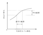
- each severity category there is an allowable range for predetermined characteristics such as wear resistance and cut resistance of the upper cover rubber in order to improve durability. If the typical rubber properties of the upper cover rubber that affect these specific specifications are set, and the degree of influence of the typical rubber properties that have been set on the specific properties is known, the usage conditions of the conveyor belt can be determined. It is possible to efficiently determine the rubber type of the upper cover rubber that brings the predetermined characteristics into an allowable range.
- the severity of usage conditions of the conveyor belt is classified into at least five categories, for example. By classifying into five or more categories, the actual usage conditions of the conveyor belt can be generally covered.
- the representative rubber physical properties include, for example, a loss factor and rubber hardness.
- the loss factor and rubber hardness greatly affect the damage of the upper cover rubber. By considering these rubber properties, it is possible to determine the specifications of the upper cover rubber with excellent durability that further matches the usage conditions. .
- the usage conditions include the ambient temperature of the place where the conveyor belt is used, a plurality of different ambient temperatures are set, and the database can be created for each ambient temperature.
- the ambient temperature has the greatest influence on the durability (life) of the conveyor belt. Therefore, if the ambient temperature is included in the use conditions, it is possible to determine a more appropriate specification of the upper cover rubber that matches the actual use conditions.
- the atmospheric temperature includes a predetermined temperature of minus 20 ° C. or lower, a predetermined temperature of 80 ° C. or higher, and a predetermined temperature of 0 ° C. or higher and 40 ° C. or lower, and at least these three atmospheric temperatures are set.
- the atmospheric temperature of the place where a conveyor belt is used can be generally covered.
- the apparent compressive stress generated by the pressing force applied to the sample was varied to perform an abrasion resistance test of rubber, and the apparent compressive stress and the test were obtained.
- a database showing the correlation between the roughness, the apparent compressive stress, and the wear amount per unit frictional energy is created, and when determining the specifications of the conveyor belt, it is given to the upper cover rubber by the transported material.
- the friction per unit frictional energy of the sample is determined.
- the amount can also be selected as the upper cover rubber of rubber species falls within the allowable range set in advance.
- a rubber abrasion resistance test is performed according to the usage conditions of each category using a plurality of rubber type samples having different viscoelastic properties, and the surface roughness of the sample obtained by the test is calculated.
- a database showing the correlation between the average wear pitch, the viscoelastic property, and the actual wear amount of the sample is created, and when determining the specifications of the conveyor belt, the viscosity of the rubber type is determined.
- the rubber type that allows the actual wear amount of the sample to fall within the preset allowable range is selected as the upper cover rubber. Rukoto can also.
- FIG. 1 is an explanatory view illustrating a conveyor belt line in a simplified manner.
- FIG. 2 is a cross-sectional view taken along the line AA in FIG.
- FIG. 3 is an explanatory diagram illustrating the state of horizontal energy and vertical energy received by the conveyor belt.
- FIG. 4 is an explanatory diagram illustrating the classified categories.
- FIG. 5 is an explanatory diagram illustrating the structure of the database.
- FIG. 6 is an explanatory view illustrating the relationship between predetermined characteristics of the upper cover rubber and typical rubber properties.
- FIG. 7 is an explanatory diagram illustrating categories for each set ambient temperature.
- FIG. 8 is an explanatory view illustrating the basic structure of the wear test apparatus.
- FIG. 9 is an explanatory view illustrating wear streaks formed on the surface of the sample.
- FIG. 1 is an explanatory view illustrating a conveyor belt line in a simplified manner.
- FIG. 2 is a cross-sectional view taken along the line AA in FIG.
- FIG. 3 is
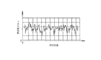
- FIG. 10 is a graph illustrating the surface roughness of the sample.
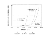
- FIG. 11 is a graph illustrating the relationship between the apparent compressive stress generated in the sample and the surface roughness.
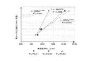
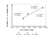
- FIG. 12 is a graph illustrating the relationship between the surface roughness of the sample and the amount of wear per unit friction energy.
- FIG. 13 is a graph illustrating the relationship between the apparent compressive stress generated in the sample and the amount of wear per unit friction energy.
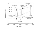
- FIG. 14 is a graph illustrating the relationship between the average wear pitch of samples and viscoelastic properties.
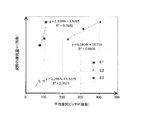
- FIG. 15 is a graph illustrating the relationship between the actual wear amount of the sample and the average wear pitch.
- a conveyed product S conveyed by another conveyor belt 7 is input to the conveyor belt 1 and conveyed to a conveyance destination by the conveyor belt 1.
- the conveyed product S may be put into the conveyor belt 1 through a hopper or the like.
- the conveyor belt 1 is stretched between pulleys 5a and 5b and is stretched with a predetermined tension.
- the conveyor belt 1 includes a core body layer 2 composed of a core body such as a canvas or a steel cord, and an upper cover rubber 3 and a lower cover rubber 4 sandwiching the core body layer 2.
- the core body layer 2 is a member that bears a tension for tensioning the conveyor belt 1.
- the lower cover rubber 4 is supported by the support roller 6, and on the return side, the upper cover rubber 3 is supported by the support roller 6 in a flat shape.
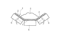
- Three support rollers 6 are arranged in the belt width direction on the carrier side of the conveyor belt 1, and the conveyor belt 1 is supported in a concave shape at a predetermined trough angle a by these support rollers 6.
- the driving pulley 5a is rotationally driven, the conveyor belt 1 operates at a predetermined traveling speed V1 in one direction.
- the conveyed product S is put on the upper cover rubber 3 and loaded on the upper cover rubber 3 to be conveyed.
- the conveyor belt 1 and another conveyor belt 7 are arranged with a vertical difference h (a difference in height h between the respective conveying surfaces).
- the conveyed product S is conveyed at a horizontal speed V0 and a vertical speed of zero.
- the kinetic energy of the conveyed product S having a mass m is (m * V0 2 ) / 2.
- the conveyed product S When the conveyed product S is loaded on the conveyor belt 1, the horizontal speed remains V0 and the vertical speed becomes zero. Then, the conveyed product S is stacked and conveyed on the conveyor belt 1 and is conveyed in the horizontal direction at the traveling speed V1 of the conveyor belt 1.
- the traveling speed V1 is higher than the horizontal speed V0 (V1> V0).
- the horizontal energy Eh (horizontal component) of the energy E received by the conveyor belt 1 by loading and transporting a transport object S of mass m onto the upper cover rubber 3 of the conveyor belt 1 is as follows ( 3) As shown in the equation. Of this energy E, vertical energy Ev (vertical component) is expressed by the following equation (4).
- Eh (m * V1 2 ) / 2 ⁇ (m * V0 2 ) / 2 (3)
- Ev mgh (4)
- EH M * (V1 2 ⁇ V0 2 ) * t / 2 / (W * L) / 1000
- EV Mgh * t / (W * L) / 1000 (6)
- M is a transport weight per unit time (kg / h)
- g is a gravitational acceleration (9.8 m / s 2 )
- V1 is a belt traveling speed (m / s)
- V0 is an initial horizontal speed of the transported object.
- W is the effective width (m) of the belt
- L is the belt length (m)
- t is the belt operating time (h).
- the effective width W of the belt is, for example, 60% to 80% of the width dimension of the conveyor belt 1, and is empirically set as a range in which the conveyed product S is loaded.
- the severity of the usage condition of the conveyor belt 1 is classified into a plurality of categories C1 to C5 as illustrated in FIG.
- the horizontal energy EH is abscissa and the vertical energy EV is ordinate, and the severity is classified into five categories C1 to C5.
- the first category C1 is a category in which the horizontal energy EH and the vertical energy EV are relatively small.
- the second category C2 is a category in which the horizontal energy EH is relatively medium and the vertical energy EV is relatively small.
- the third category C3 is a category in which the horizontal energy EH is relatively small and the vertical energy EV is relatively medium.
- the fourth category C4 is a category in which the horizontal energy EH and the vertical energy EV are relatively medium.
- the fifth category C5 is a category in which the horizontal energy EH and the vertical energy EV are relatively large.
- the number of categories is not limited to five, but can be three, four, or more than six categories. However, if the number of categories becomes excessive, data analysis or the like becomes complicated, so the number of categories should be about 10 as an upper limit. If classified into at least five categories, the actual use conditions of the conveyor belt 1 can be generally covered. As described above, for the conveyor belt 1 with various usage conditions and various specifications of the upper cover rubber 3, data is acquired for predetermined characteristics including wear resistance and cut resistance, and each characteristic is actually used. In addition, grasp the appropriate tolerance without excess or deficiency.
- a database DB1 in which an allowable range is set in advance for predetermined characteristics including at least wear resistance and cut resistance of the upper cover rubber 3 for each category C1 to C5 is created in advance.
- the database DB1 is input and stored in the arithmetic device 8 such as a personal computer.
- test method for wear resistance, specify the test method and set a practically acceptable tolerance for that category.
- test method include a DIN wear test, a lamborn wear test, a pico wear test, an acron wear test, and the like.
- the allowable range of the wear amount in the specified wear test is set.
- ⁇ ⁇ For cut resistance, specify the test method in the same way, and set a practically acceptable tolerance for that category. Specifically, a test method for dropping a blade having a predetermined specification (shape and weight) from a predetermined height can be exemplified. The allowable range of the cut depth in the specified cut resistance test is set.
- predetermined characteristics of the upper cover rubber necessary characteristics can be appropriately incorporated in addition to wear resistance and cut resistance.
- chipping resistance is incorporated, test methods are similarly specified for chipping resistance, and allowable ranges that are practically sufficient are not set for each category.
- representative rubber physical properties of the upper cover rubber 3 that affect predetermined characteristics such as wear resistance and cut resistance are set.
- Typical rubber physical properties include loss factor (tan ⁇ ) and rubber hardness, 100% modulus (tensile stress at 100% elongation), breaking strength, breaking elongation, and the like.
- Representative rubber physical properties are not limited to these, and can be appropriately adopted as long as it greatly affects the predetermined characteristics of the upper cover rubber 3 according to the predetermined characteristics.
- the loss coefficient is a ratio (G ′′ / G ′) of the storage shear elastic modulus G ′ and the loss shear elastic modulus G ′′, and how much energy is absorbed when the upper cover rubber 3 is deformed (in heat) Change). The larger the value of the loss factor, the more energy is absorbed.
- HYPERLINK http://www.taica.co.jp/gel/words/ha.html” ⁇ l "01" rebound resilience decreases, In the vibration test, the resonance magnification becomes low.
- the degree of influence on predetermined characteristics is known. For example, the effects of loss factor, rubber hardness, 100% modulus, breaking strength, breaking elongation, etc. on the wear resistance, cut resistance, chipping resistance, etc. of the upper cover rubber 3 are grasped. Specifically, “if the loss factor of the upper cover rubber 3 is within this range, the wear resistance is within this range with respect to the allowable range.” “If the loss factor is changed to this extent, the wear resistance becomes Understand the contents of “changes to the extent” from various experiments and experiences.
- horizontal energy EH and vertical energy EV are calculated from the usage conditions of the conveyor belt 1.
- the category of the severity of the usage condition of the conveyor belt 1 is specified.
- the calculated horizontal energy EH and vertical energy EV are input to the arithmetic unit 8 and, based on the input calculation result, to which category the usage condition of the conveyor belt 1 is stored in the database DB1. To identify the most matching category.
- the permissible range of predetermined characteristics such as wear resistance and cut resistance of the upper cover rubber 3 is found in the category.
- a typical rubber characteristic of the upper cover rubber 3 that affects the characteristic is set. Therefore, an appropriate range for the representative rubber physical properties is specified so that the predetermined characteristics are within the allowable range in the specified category.
- the thickness of the upper cover rubber 3 is determined based on the service life required for the conveyor belt 1. In this way, the specifications of the upper cover rubber 3 are determined.
- the severity of the usage condition of the conveyor belt 1 is classified into a plurality of categories using the horizontal energy EH and the vertical energy EV received by the conveyor belt 1 when the conveyed product S is loaded and conveyed.
- the horizontal energy EH largely affects the wear amount of the upper cover rubber 3
- the vertical energy EV largely affects the size and occurrence frequency of cut scratches on the upper cover rubber 3. It becomes easy to sort.
- each severity category there is an allowable range for predetermined characteristics such as wear resistance and cut resistance of the upper cover rubber 3 in order to improve durability.
- the representative rubber physical properties of the upper cover rubber 3 that affect these predetermined specifications are set, and the degree of influence on the predetermined characteristics by the set representative rubber physical properties is known, the usage conditions of the conveyor belt 1 are determined. Therefore, it is possible to efficiently determine the rubber type of the upper cover rubber 3 that brings the predetermined characteristics into an allowable range. That is, it is possible to efficiently determine the specifications of the upper cover rubber 3 having durability that is not excessive or insufficient with respect to use conditions without spending a great deal of labor.
- the loss factor and rubber hardness of the upper cover rubber 3 greatly affect the degree of damage to the upper cover rubber 3. Therefore, considering these as representative rubber physical properties, it is advantageous to determine the specifications of the upper cover rubber 3 that is more excellent in durability that matches the use conditions.
- the database DB1 is created for each type of the conveyed product S, the specifications of the upper cover rubber 3 having durability that matches the usage conditions of the conveyor belt 1 can be determined.
- the ambient temperature T at the place where the conveyor belt 1 is installed has the greatest influence on the durability (life) of the conveyor belt 1.
- the atmospheric temperature T when the conveyor belt 1 is used under hot weather is, for example, close to plus 100 ° C.
- the atmospheric temperature T when the conveyor belt 1 is used in a cold region is, for example, minus 20 ° C. or lower.
- the rubber properties are relatively high in temperature dependence, and as the ambient temperature T increases, the rubber hardness, 100% modulus, breaking strength, etc. generally decrease and the elongation at break generally increases. Therefore, when considering the durability of the conveyor belt T, the ambient temperature T is the most important factor among the usage conditions of the conveyor belt 1.
- the severity is classified into a plurality of categories C1 to C5 for each ambient temperature T.
- the database DB1 described above is classified into a plurality of categories C1 to C5.
- the categories are two-dimensionally classified by setting the ambient temperature T to a specific predetermined temperature using the horizontal energy EH and the vertical energy EV as indices.
- categories are classified three-dimensionally by setting a plurality of ambient temperatures T and classifying the categories for each ambient temperature T. As described above, when the ambient temperature T is included in the usage conditions of the conveyor belt 1, a more appropriate specification of the upper cover rubber 3 that matches the actual usage conditions can be determined.
- the set ambient temperature T is a predetermined temperature of minus 20 ° C. or lower, a predetermined temperature of 80 ° C. or higher, and a temperature of 0 ° C. or higher plus 40 It is preferable to set at least these three atmospheric temperatures T including a predetermined temperature of less than or equal to ° C. More preferably, at least five atmosphere temperatures T are set including a predetermined temperature of minus 20 ° C. or lower, a predetermined temperature of 80 ° C. or higher, and three predetermined temperatures of 0 ° C. or higher plus 60 ° C. or lower. When only one atmosphere temperature T is set as shown in FIG. 4 without setting a plurality of atmosphere temperatures T, for example, one predetermined temperature within the range of plus 20 ° C. to plus 40 ° C. is set as the ambient temperature. Set to T to create the above-described database DB1.
- an appropriate specification of the upper cover rubber 3 that matches the actual use conditions can be determined using another database DB2 input and stored in the arithmetic unit 8.
- a known abrasion resistance test is performed using rubber sample B to obtain data.
- a known abrasion resistance test a pico abrasion test, a DIN abrasion test, a rambone abrasion test, a Taber abrasion test, a Williams abrasion test, an acron abrasion test, or the like can be used.
- the rubber wear test apparatus 9 generally includes a pressing body 10, a pressing mechanism 11 that presses the pressing body 10 against the rubber sample B, and the pressing body 10 and the sample B relative to each other. And a relative movement mechanism 12 for movement.
- the pressure body 10 is moved relative to the sample B while being pressed to cause the sample B to wear, and the amount of wear and the wear mode are grasped.
- the specification of the press body 10, the press mechanism 11, and the relative movement mechanism 12 differs in the well-known abrasion test method mentioned above, respectively.
- the apparent compressive stress Pe generated by the pressing force applied to the sample B is varied, and the relationship between the apparent compressive stress Pe and the surface roughness R of the sample B obtained by the test.
- wear streaks L are formed on the surface of the sample B at intervals in the frictional direction FD as illustrated in FIG.
- the surface roughness R of the sample B is as illustrated in FIG.
- the arithmetic average roughness Ra defined in JIS is used as the surface roughness R.
- the maximum height (Ry), the ten-point average roughness (Rz), etc. can be used in addition to the arithmetic average roughness Ra.
- Each of the known wear resistance tests differs in the apparent compressive stress Pe generated in the sample B. Therefore, when a plurality of different known wear resistance tests are performed, the apparent compressive stress Pe is varied to perform the wear resistance test. Will do. For example, compressive stress pe the apparent, DIN abrasion test, Pico abrasion test, respectively in Lambourn abrasion test, 0.05N / mm 2, 138.5N / mm 2, a 0.333N / mm 2. As the wear resistance test, at least one of a DIN wear test and a pico wear test may be used.
- FIG. 11 is a semi-logarithmic graph, in which three types of samples B1, B2, and B3 having different rubber types are used, and data obtained by performing three types of different abrasion resistance tests on the respective samples are described. .
- the apparent compressive stress Pe on the vertical axis is displayed as an index, and the larger the index, the greater the apparent compressive stress Pe.
- the surface roughness R surface roughness Ra in FIG. 11
- the wear amount K1 is calculated by the actual wear amount Vr / (contact area between the sample B and the pressing body 10 ⁇ tensile strength TB of the sample B rubber ⁇ friction distance).
- the relationship between the acquired surface roughness R and the wear amount K1 is highly correlated as illustrated in FIG.
- the wear amount K1 on the vertical axis is displayed as an index, and the larger the index, the greater the wear amount K1. That is, the greater the surface roughness R, the greater the wear amount K1.
- the unit contact area wear amount K2 can be used instead.
- the unit contact area wear amount K2 is calculated by the actual wear amount Vr / (contact area between the sample B and the pressing body 9) of the sample B.
- the relationship between the acquired surface roughness R and the wear amount K2 is also highly correlated similarly to the relationship between the acquired surface roughness R and the wear amount K1.
- the relationship between the apparent compressive stress Pe and the wear amount K1 can be acquired.
- the relationship between the apparent compressive stress Pe and the wear amount K1 is also highly correlated as illustrated in the semilogarithmic graph of FIG. That is, the wear amount K1 increases as the apparent compressive stress Pe increases.
- a database DB2 indicating the correlation between the surface roughness R, the apparent compressive stress Pr, and the wear amount K1 per unit frictional energy is created based on the relationships illustrated in FIGS.
- the apparent compressive stress Pr generated in the upper cover rubber 3 at the site of use is acquired and input to the arithmetic unit 8. Since the use conditions of the conveyor belt 1 are known, the apparent compressive stress Pr can be obtained by calculating from the known conditions.
- the amount of wear K1 per unit friction energy is calculated by the actual amount of wear Vr of sample B / (contact area between sample B and pressing body 10 ⁇ tensile strength TB of sample B rubber ⁇ friction distance).
- the Therefore, the actual wear amount X of the upper cover rubber 3 at the use site can be calculated based on the calculated wear amount K1 and the contact area Ar between the conveyed product S and the upper cover rubber 3 at the use site. it can.
- An allowable range of the actual wear amount of the upper cover rubber 3 is set in advance, and a rubber type having the calculated wear amount X within the allowable range can be selected as the upper cover rubber 3.
- the average wear pitch P is an interval between the wear streaks L adjacent in the friction direction FD as illustrated in FIG.
- FIG. 14 shows data obtained by performing three different types of wear resistance tests E1, E2, and E3 on three types of samples B1, B2, and B3 having different rubber types. Yes.
- the average wear pitch P on the vertical axis is displayed as an index, and the larger the index, the greater the average wear pitch P.
- RRF Rolling Resistance Factor
- RRF Rolling Resistance Factor
- RRF is an index representing the dynamic viscoelasticity of rubber. The smaller this value, the faster the rebound speed of rubber and the better the performance of shortening the response delay.
- the average wear pitch P varies depending on the rubber type, and the average wear pitch P increases as the viscoelastic property RRF of the rubber increases.
- a relationship between the average wear pitch P and the actual wear amount Vr of the sample B obtained by the test is obtained by a known wear resistance test.
- the relationship between the average wear pitch P and the actual wear amount Vr is highly correlated as illustrated in FIG. 15, and the actual wear amount Vr of the sample B increases as the average wear pitch P increases.
- the actual wear amount Vr on the vertical axis is indicated by an index, and the larger the index, the greater the actual wear amount Vr.
- the relationship between the viscoelastic property RRF and the actual wear amount Vr can be acquired. Then, a database DB3 indicating the correlation among the average wear pitch P, the viscoelastic characteristic RRP, and the actual wear amount Vr of the sample B is created based on the acquired relationships illustrated in FIGS.
- the rubber type (viscoelastic property RRF) of the upper cover rubber 3 to be used is input to the arithmetic unit 8, and the data illustrated in FIG.
- the average wear pitch P in the wear resistance test is calculated using data of the same kind of rubber (same viscoelastic property RRF) as the upper cover rubber 3 to be used.
- an optimal rubber type is selected as the upper cover rubber 3 from the rubber type selected using the database DB1, the rubber type selected using the database DB2, and the rubber type selected using the database DB3. .
- the rubber type selected in common using the three databases DB1, 2, and 3 is selected, or the rubber type selected in common using the databases DB1 and B2, or the database DB1 is selected.
- the selection criteria are set as appropriate, such as selecting a rubber type selected in common using B3.
Landscapes
- Engineering & Computer Science (AREA)
- Mechanical Engineering (AREA)
- Belt Conveyors (AREA)
Abstract
Description
E0=(m*V02)/2+mgh・・・(1)
E1=(m*V12)/2・・・(2)
Eh=(m*V12)/2-(m*V02)/2・・・(3)
Ev=mgh・・・(4)
EH=M*(V12-V02)*t/2/(W*L)/1000・・・(5)
EV=Mgh*t/(W*L)/1000・・・(6)
ここで、Mは単位時間あたりの搬送重量(kg/h)、gは重力加速度(9.8m/s2)、V1はベルト走行速度(m/s)、V0は搬送物の初期水平方向速度(m/s)、Wはベルトの有効幅(m)、Lはベルト長さ(m)、tはベルト稼働時間(h)である。尚、ベルトの有効幅Wは、コンベヤベルト1の幅寸法の例えば60%~80%であり、搬送物Sが積載される範囲として経験的に設定される。
2 心体層
3 上カバーゴム
4 下カバーゴム
5a、5b プーリ
6 支持ローラ
7 別のコンベヤベルト
8 演算装置
9 摩耗試験装置
10 押圧体
11 押圧機構
12 相対移動機構
B サンプル
C1~C5 カテゴリ
DB1、DB2、DB3 データベース
S 搬送物
T 雰囲気温度
Claims (7)
- コンベヤベルトの上カバーゴムの上に搬送物を投入して積載搬送することによりコンベヤベルトが受ける水平方向エネルギおよび垂直方向エネルギを指標にして、コンベヤベルトの使用条件のシビアリティを複数のカテゴリに分類し、それぞれのカテゴリ毎に前記上カバーゴムの少なくとも耐摩耗性および耐カット性を含む所定の特性について許容範囲を設定したデータベースを作成するとともに、それぞれの前記所定の特性に影響する上カバーゴムの代表的なゴム物性を設定し、設定した代表的なゴム物性による前記所定の特性に対する影響具合を把握しておき、コンベヤベルトの仕様を決定する際には、そのコンベヤベルトの使用条件から前記データベースに基づいてそのシビリアティのカテゴリを特定するとともに、その特定したカテゴリにおいて前記所定の特性を許容範囲内にさせる前記代表的なゴム物性の適切な範囲を特定し、前記代表的なゴム物性がこの特定した適切な範囲内にあるゴム種を上カバーゴムとして選択することを特徴とするコンベヤベルトの仕様決定方法。
- 前記コンベヤベルトの使用条件のシビアリティを少なくとも5つのカテゴリに分類する請求項1に記載のコンベヤベルトの仕様決定方法。
- 前記代表的なゴム物性に、損失係数およびゴム硬度が含まれる請求項1または2に記載のコンベヤベルトの仕様決定方法。
- 前記使用条件に、コンベヤベルトが使用される場所の雰囲気温度が含まれ、異なる複数の雰囲気温度が設定されて、それぞれの雰囲気温度について前記データベースを作成する請求項1~3のいずれかに記載のコンベヤベルトの仕様決定方法。
- 前記雰囲気温度に、マイナス20℃以下の所定温度、プラス80℃以上の所定温度および0℃以上プラス40℃以下の所定温度が含まれ、少なくともこれら3つの雰囲気温度が設定される請求項4に記載のコンベヤベルトの仕様決定方法。
- ゴム種毎にサンプルを用いて、前記サンプルに付与される押圧力によって生じる見かけの圧縮応力を異ならせてゴムの耐摩耗性試験を行い、前記見かけの圧縮応力とその試験により得られた前記サンプルの表面粗さとの関係を取得し、かつ、前記表面粗さとその試験により得られた前記サンプルの単位摩擦エネルギ当たりの摩耗量と関係を取得し、これら取得した関係に基づいて、前記表面粗さと前記見かけの圧縮応力と前記単位摩擦エネルギ当たりの摩耗量との相関関係を示すデータベースを作成し、コンベヤベルトの仕様を決定する際には、上カバーゴムに対して運搬物により付与される押圧力によって生じる見かけの圧縮応力と、前記相関関係を示すデータベースとに基づいて、前記サンプルの単位摩擦エネルギ当たりの摩耗量が予め設定した許容範囲内になるゴム種を上カバーゴムとして選択する請求項1~5のいずれかに記載のコンベヤベルトの仕様決定方法。
- 粘弾性特性が異なる複数のゴム種のサンプルを用いて、前記カテゴリそれぞれの使用条件に対応させてゴムの耐摩耗性試験を行い、その試験により得られた前記サンプルの表面粗さから算出される平均摩耗ピッチとそのサンプルのゴム種の粘弾性特性との関係を取得し、かつ、前記平均摩耗ピッチとその試験により得られた前記サンプルの実際の摩耗量との関係を取得し、これら取得した関係に基づいて、前記平均摩耗ピッチと前記粘弾性特性と前記サンプルの実際の摩耗量との相関関係を示すデータベースを作成し、コンベヤベルトの仕様を決定する際には、ゴム種の粘弾性特性と、前記相関関係を示すデータベースとに基づいて、前記サンプルの実際の摩耗量が予め設定した許容範囲内になるゴム種を上カバーゴムとして選択する求項1~5のいずれかに記載のコンベヤベルトの仕様決定方法。
Priority Applications (5)
| Application Number | Priority Date | Filing Date | Title |
|---|---|---|---|
| US15/568,790 US10656055B2 (en) | 2015-04-23 | 2016-03-28 | Conveyor belt specification determining method |
| RU2017134818A RU2017134818A (ru) | 2015-04-23 | 2016-03-28 | Способ определения технической характеристики конвейерной ленты |
| CN201680017290.8A CN107406200B (zh) | 2015-04-23 | 2016-03-28 | 传送带的规格决定方法 |
| AU2016252952A AU2016252952B2 (en) | 2015-04-23 | 2016-03-28 | Conveyor belt specification determining method |
| EP16782951.4A EP3287397B1 (en) | 2015-04-23 | 2016-03-28 | Conveyor belt specification determining method |
Applications Claiming Priority (4)
| Application Number | Priority Date | Filing Date | Title |
|---|---|---|---|
| JP2015088024 | 2015-04-23 | ||
| JP2015-088024 | 2015-04-23 | ||
| JP2015186890A JP6065079B2 (ja) | 2015-04-23 | 2015-09-24 | コンベヤベルトの仕様決定方法 |
| JP2015-186890 | 2015-09-24 |
Publications (1)
| Publication Number | Publication Date |
|---|---|
| WO2016170929A1 true WO2016170929A1 (ja) | 2016-10-27 |
Family
ID=57143203
Family Applications (1)
| Application Number | Title | Priority Date | Filing Date |
|---|---|---|---|
| PCT/JP2016/059956 Ceased WO2016170929A1 (ja) | 2015-04-23 | 2016-03-28 | コンベヤベルトの仕様決定方法 |
Country Status (1)
| Country | Link |
|---|---|
| WO (1) | WO2016170929A1 (ja) |
Citations (3)
| Publication number | Priority date | Publication date | Assignee | Title |
|---|---|---|---|---|
| JPS60177042A (ja) * | 1984-02-21 | 1985-09-11 | Ube Ind Ltd | ゴムベルト |
| JP2001026670A (ja) * | 1999-07-15 | 2001-01-30 | Bridgestone Corp | ベルト用ゴム組成物 |
| JP2009035373A (ja) * | 2007-08-01 | 2009-02-19 | Bando Chem Ind Ltd | スチールコードコンベヤベルト |
-
2016
- 2016-03-28 WO PCT/JP2016/059956 patent/WO2016170929A1/ja not_active Ceased
Patent Citations (3)
| Publication number | Priority date | Publication date | Assignee | Title |
|---|---|---|---|---|
| JPS60177042A (ja) * | 1984-02-21 | 1985-09-11 | Ube Ind Ltd | ゴムベルト |
| JP2001026670A (ja) * | 1999-07-15 | 2001-01-30 | Bridgestone Corp | ベルト用ゴム組成物 |
| JP2009035373A (ja) * | 2007-08-01 | 2009-02-19 | Bando Chem Ind Ltd | スチールコードコンベヤベルト |
Non-Patent Citations (1)
| Title |
|---|
| See also references of EP3287397A4 * |
Similar Documents
| Publication | Publication Date | Title |
|---|---|---|
| JP6065079B2 (ja) | コンベヤベルトの仕様決定方法 | |
| Hakami et al. | Developments of rubber material wear in conveyer belt system | |
| US10377575B2 (en) | Method of recognizing conveyor belt wear condition | |
| Fedorko et al. | Influence of selected characteristics on failures of the conveyor belt cover layer material | |
| Li et al. | Evolution of microscopic characteristics of rolling contact fatigue coexisting with wear of U75V rail | |
| Ambriško et al. | Investigating the tension load of rubber composites by impact dynamic testing | |
| WO2016170929A1 (ja) | コンベヤベルトの仕様決定方法 | |
| Molnar et al. | Friction and wear characterization of the tribosystem scraper versus rubber in conveyor systems | |
| WO2019064758A1 (ja) | コンベヤベルトの寿命予測方法 | |
| JP6565677B2 (ja) | コンベヤベルトの仕様決定方法 | |
| Ambriško et al. | Experimental research of a new generation of support systems for the transport of mineral raw materials. | |
| CN107850519B (zh) | 传送带的耐冲击性评价方法 | |
| Hakami et al. | Wear of rubber material in conveyor belt system | |
| JPWO2018185976A1 (ja) | ゴム部材の耐衝撃性評価方法 | |
| Youssef | Development of conveyor belts design for reducing energy consumption in mining applications | |
| JP7110551B2 (ja) | コンベヤベルト | |
| JP6606928B2 (ja) | コンベヤベルトの耐摩耗性評価方法 | |
| AU2017252992B2 (en) | Rubber selection method | |
| ShaoLei et al. | STUDY ON THE INFLUENCE OF DIFFERENT LUBRICATION STATES ON BENDING FATIGUE CHARACTERISTICS OF WIRE ROPE (MT) | |
| Santos et al. | Belt Rotation in Pipe Conveyors: Failure Mode Analysis and Overlap Stability Assessment. Sustainability 2023, 15, 11312 | |
| Roberts et al. | Recent research developments in belt conveyor technology |
Legal Events
| Date | Code | Title | Description |
|---|---|---|---|
| 121 | Ep: the epo has been informed by wipo that ep was designated in this application |
Ref document number: 16782951 Country of ref document: EP Kind code of ref document: A1 |
|
| WWE | Wipo information: entry into national phase |
Ref document number: 2017134818 Country of ref document: RU |
|
| ENP | Entry into the national phase |
Ref document number: 2016252952 Country of ref document: AU Date of ref document: 20160328 Kind code of ref document: A |
|
| WWE | Wipo information: entry into national phase |
Ref document number: 15568790 Country of ref document: US |
|
| NENP | Non-entry into the national phase |
Ref country code: DE |