WO2016171063A1 - 光音響波検出装置、光音響イメージング装置 - Google Patents
光音響波検出装置、光音響イメージング装置 Download PDFInfo
- Publication number
- WO2016171063A1 WO2016171063A1 PCT/JP2016/061992 JP2016061992W WO2016171063A1 WO 2016171063 A1 WO2016171063 A1 WO 2016171063A1 JP 2016061992 W JP2016061992 W JP 2016061992W WO 2016171063 A1 WO2016171063 A1 WO 2016171063A1
- Authority
- WO
- WIPO (PCT)
- Prior art keywords
- lens
- photoacoustic
- acoustic
- frequency
- light
- Prior art date
- Legal status (The legal status is an assumption and is not a legal conclusion. Google has not performed a legal analysis and makes no representation as to the accuracy of the status listed.)
- Ceased
Links
Images
Classifications
-
- A—HUMAN NECESSITIES
- A61—MEDICAL OR VETERINARY SCIENCE; HYGIENE
- A61B—DIAGNOSIS; SURGERY; IDENTIFICATION
- A61B5/00—Measuring for diagnostic purposes; Identification of persons
- A61B5/0093—Detecting, measuring or recording by applying one single type of energy and measuring its conversion into another type of energy
- A61B5/0095—Detecting, measuring or recording by applying one single type of energy and measuring its conversion into another type of energy by applying light and detecting acoustic waves, i.e. photoacoustic measurements
-
- A—HUMAN NECESSITIES
- A61—MEDICAL OR VETERINARY SCIENCE; HYGIENE
- A61B—DIAGNOSIS; SURGERY; IDENTIFICATION
- A61B8/00—Diagnosis using ultrasonic, sonic or infrasonic waves
- A61B8/13—Tomography
-
- G—PHYSICS
- G01—MEASURING; TESTING
- G01N—INVESTIGATING OR ANALYSING MATERIALS BY DETERMINING THEIR CHEMICAL OR PHYSICAL PROPERTIES
- G01N29/00—Investigating or analysing materials by the use of ultrasonic, sonic or infrasonic waves; Visualisation of the interior of objects by transmitting ultrasonic or sonic waves through the object
- G01N29/34—Generating the ultrasonic, sonic or infrasonic waves, e.g. electronic circuits specially adapted therefor
Definitions
- the present invention relates to a photoacoustic wave detection device that irradiates an observation target such as a biological tissue with light and detects an acoustic wave emitted from the observation target by the irradiation light, and a photoacoustic imaging device using the photoacoustic wave detection device. .
- a photoacoustic imaging technique using a photoacoustic effect has attracted attention as a technique for imaging (visualization, imaging) the inside of a living body.
- the photoacoustic effect is a phenomenon in which molecules that absorb light energy release heat, and an acoustic wave is generated by volume expansion due to the heat. Since a sound wave can propagate in a living body for a long distance, photoacoustic imaging has a feature that a deep part of a living body can be visualized with high contrast.
- Non-Patent Document 1 describes that a biological tissue is irradiated with a short pulse laser to detect acoustic waves generated by instantaneous thermal expansion of the biological tissue. Since it can be known from which depth the acoustic wave arrives at the arrival time of the acoustic wave, internal imaging can be performed based on the detected acoustic wave.
- Non-Patent Document 2 describes that internal imaging is performed by irradiating a living tissue with an inexpensive normal continuous wave laser instead of a short pulse laser. This does not cause instantaneous thermal expansion to the living tissue like a short pulse laser, but continuously stimulates the living tissue with a continuous wave laser with an intensity modulation of about MHz in the ultrasonic band.
- imaging is performed by detecting the acoustic waves generated in the same band. Since continuous wave lasers cannot determine the depth based on the arrival time of acoustic waves, a large arch-shaped acoustic wave measuring device for separating acoustic waves generated from various depths of living tissue is required.
- Non-Patent Document 1 and Non-Patent Document 2 the resolution in the depth direction (optical axis direction) is determined by the properties of sound waves. Therefore, there is a problem that it is difficult to increase the resolution.
- Patent Document 1 discloses that the resolution in the depth direction is improved by utilizing the multiphoton excitation phenomenon. This technique improves the resolution in the depth direction by utilizing the property of light called multiphoton excitation rather than the property of sound waves.
- an object of the present invention is to provide a high-resolution photoacoustic imaging apparatus at a low cost.
- the photoacoustic wave detection device includes a beam splitter that branches light emitted from a light source and at least branch light so that the branched light interferes with each other.
- a photophysical property shift unit that changes one physical property, a lens in which each of the branched lights is incident in parallel to the optical axis, and an acoustic wave generated in a focal region of the lens in an observation target are detected.
- an acoustic detection unit can shift at least one frequency of the branched light.
- the acoustic detection unit detects an acoustic wave for a difference frequency band of the branched light in which at least one frequency is shifted.
- the photophysical characteristic shift unit may add phase modulation of a constant frequency to at least one of the branched lights.
- the lens can be a variable focus lens.
- a photoacoustic imaging apparatus includes an inside of the observation object based on the photoacoustic wave detection apparatus described above and a detection signal detected by the acoustic detection unit. And a control device for generating an image.
- a high-resolution photoacoustic imaging apparatus can be provided at low cost.
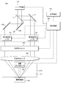
- FIG. 1 is a block diagram illustrating a configuration of a photoacoustic imaging apparatus 100 to which the photoacoustic wave detection apparatus according to the present embodiment is applied.
- the photoacoustic imaging apparatus 100 is an apparatus that performs internal imaging of an observation target 200 such as a living tissue, and includes a laser light source 110, a beam splitter 111, a mirror 112, a mirror 113, a mirror 114, and a first frequency.
- a shifter 121, a second frequency shifter 122, an optical scanning unit 130, a variable focus lens 140, an acoustic transducer 150, a control device 160, and a display device 170 are provided.
- the laser light source 110 is a light source that emits parallel laser light.
- the laser light source 110 can be, for example, a semiconductor laser light source that emits continuous light.
- a wavelength having large absorption in the observation object 200 is selected. For example, when a blood vessel is imaged as the observation object 200, it is desirable to select a wavelength in the vicinity of 532 nm at which hemoglobin absorption is large.
- a beam splitter 111 that divides light into two equal parts is disposed.
- One branched light from the beam splitter 111 is guided to the first frequency shifter 121 by the mirror 112 and the mirror 113, and the other branched light is guided to the second frequency shifter 122 by the mirror 114.
- the first frequency shifter 121 and the second frequency shifter 122 constitute a frequency shift unit 120 and function as a photophysical characteristic shift unit that changes the physical characteristics of light.
- the beam splitter 111 arranged at 45 degrees with respect to the emission direction of the laser light source 110 branches the light in the straight traveling direction and the light in the 90 degree direction, and the light in the straight traveling direction is inclined by 45 degrees.
- the mirror 112 and the mirror 113 travel in the same direction as the emission direction of the laser light source 110 and enter the first frequency shifter 121.
- the light branched in the 90-degree direction by the beam splitter 111 travels in the same direction as the emission direction of the laser light source 110 by the mirror 114 inclined by 45 degrees and enters the second frequency shifter 122.
- each light branched by the beam splitter 111 enters the first frequency shifter 121 and the second frequency shifter 122 in the same direction. To do.
- the first frequency shifter 121 and the second frequency shifter 122 are constituted by, for example, acousto-optic modulators, and slightly shift the frequency of light.
- the frequency shift amount of the first frequency shifter 121 and the frequency shift amount of the second frequency shifter 122 are different values.
- One frequency shift amount may be zero.
- the two branched lights at least one of which is frequency-shifted by the frequency shift unit 120, travel in the same direction, enter the variable focus lens 140 via the optical scanning unit 130, and focus on each.
- the two lights are configured to enter parallel to the optical axis of the variable focus lens 140. Therefore, the two lights intersect at the focal point of the variable focus lens 140.
- the optical scanning unit 130 has a galvanometer mirror or the like, and scans the focal point in at least one direction on the plane orthogonal to the optical axis of the variable focus lens 140.
- the variable focus lens 140 is a lens that can change the focal length, and it is desirable to select a lens that can change the focal position at high speed.
- a medium container 210 containing a medium 211 such as water for transmitting acoustic waves is disposed at the tip of the variable focus lens 140, and an observation object 200 such as a living tissue is fixed to the bottom surface of the medium container 210. As shown in this figure, the variable focus of the variable focus lens 140 is located inside the observation object 200.
- an acoustic transducer 150 that functions as an acoustic detection unit is disposed in the medium 211 in the medium container 210.
- the acoustic transducer 150 detects an acoustic wave emitted from the observation object 200 and converts it into an electrical signal.
- the above-described beam splitter 111, mirrors 112 to 114, frequency shift unit 120, optical scanning unit 130, varifocal lens 140, and acoustic transducer 150 form the photoacoustic wave detection device of this embodiment.
- the control device 160 is a block that controls the laser light source 110, the frequency shift unit 120, the optical scanning unit 130, the variable focus lens 140, and the acoustic transducer 150, and a display device 170 is connected to the control device 160.
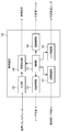
- FIG. 2 is a block diagram showing the configuration of the control device 160.
- the control device 160 includes a light source control unit 161, a modulation control unit 162, a lens control unit 163, a scanning control unit 164, an input unit 165, an image generation unit 166, and a control unit 167.
- the light source controller 161 controls the light emission process of the laser light source 110.
- the modulation control unit 162 controls the frequency shift amount of the frequency shift unit 120.
- the lens control unit 163 controls the focal length of the variable focus lens 140.
- the scanning control unit 164 controls the operation position of the optical scanning unit 130.
- the input unit 165 inputs a detection signal from the acoustic transducer 150.
- the image generation unit 166 generates and stores an internal image of the observation object 200 based on the detection signal, information on the focal position of the variable focus lens 140, and the like, and outputs the internal image to the display device 170 or the like as necessary.
- the control unit 167 controls various operations in the light source control unit 161, the modulation control unit 162, the lens control unit 163, the scanning control unit 164, and the image generation unit 166.
- the laser light source 110 starts oscillating and emits laser light.
- This laser beam is divided into two equal parts by the beam splitter 111 and branched into light traveling in a straight direction and a 90-degree direction (right side in FIG. 1).
- the light traveling straight is guided to the first frequency shifter 121 by the mirror 112 and the mirror 113, and the light traveling in the 90 degree direction is guided to the second frequency shifter 122 by the mirror 114.
- the modulation control unit 162 of the control device 160 is set so that the first frequency shifter 121 shifts the light frequency by 10 MHz, and the second frequency shifter 122 shifts the light frequency by 12 MHz.
- the light shifted to different frequencies by the first frequency shifter 121 and the second frequency shifter 122 passes through the optical scanning unit 130 and enters the variable focus lens 140. Each light is focused by the action of the variable focus lens 140.
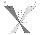
- FIG. 3 schematically shows the vicinity of the focal point of the variable focus lens 140.
- light that has passed through the first frequency shifter 121 is indicated by L1
- light that has passed through the second frequency shifter 122 is indicated by L2.
- the two lights L1 and L2 are incident in parallel to the optical axis of the varifocal lens 140, they intersect at the focal point of the varifocal lens 140 to form an intersecting region F1.
- the intersection region F1 is positioned inside the observation object 200.
- the light L1 and the light L2 have slightly different frequencies, the light L1 and the light L2 interfere with each other in the intersection region F1, and intensity modulation of the difference frequency is performed.
- the difference frequency is 2 MHz
- the intensity modulation is 2 MHz. That is, the intensity-modulated light at 2 MHz is irradiated only in the intersection region F1.
- the 2 MHz optical stimulus is absorbed and converted into a thermal stimulus.
- the object 200 is periodically heated and the observation object 200 undergoes thermal expansion.
- a 2 MHz acoustic wave is emitted from the area
- the greater the light absorption the stronger the acoustic wave generated because the amount of conversion to thermal stimulation increases.
- the acoustic wave generated inside the observation object 200 propagates through the medium 211 accommodated in the medium container 210, is detected by the acoustic transducer 150, and is converted into a detection signal of an electric signal. At this time, a band around 2 MHz, which is the difference frequency, is extracted by a filter or the like (not shown).
- the detection signal is input to the input unit 165 of the control device 160 and temporarily stored.
- intersection area F1 that is an acoustic generation area can be moved in the depth direction by the lens control unit 163 of the control device 160 changing the focal length of the variable focus lens 140. For this reason, the control apparatus 160 can acquire the detection signal of an acoustic wave, changing the position of the intersection area
- the variable focal length lens 140 can change the focal length at high speed, scanning in the depth direction can be performed at high speed.
- the scanning control unit 164 of the control device 160 controls the optical scanning unit 130, so that the intersection region F1 can be moved on a plane orthogonal to the optical axis of the variable focus lens 140.
- the movement is made in one direction (horizontal direction), but the movement may be made in two directions (vertical and horizontal directions).
- control device 160 can acquire the distribution of the magnitude of the acoustic wave for the cross section of the observation object 200.
- This distribution indicates a distribution of the magnitude of absorption of light having a wavelength emitted by the laser light source 110.
- the image generation unit 166 is based on the detection signal temporarily stored by the input unit 165, the focal length information of the variable focus lens 140 and the scanning position information of the optical scanning unit 130 acquired from the control unit 167. Are generated and stored, or displayed on the display device 170.
- the generation source of the acoustic wave is a very limited area of only the intersection area F1 where two lights intersect at the focal point. For this reason, high resolution can be obtained. Further, the laser light source 110 only needs to emit a continuous wave, and a special pulse laser is unnecessary, so that it can be realized at low cost.
- the scanning in the depth direction is performed by changing the focal length of the variable focus lens 140, the position in the depth direction of the acoustic wave generation can be easily specified.
- the frequency shift unit 120 including the first frequency shifter 121 and the second frequency shifter 122 is used.
- the first frequency shifter 121 is used.
- Any one of the second frequency shifters 122 may be omitted.
- the intensity-modulated light having the difference frequency of the branched light is irradiated only in the intersection area F1, but an image may be generated by changing the difference frequency.
- an acoustic wave image corresponding to the difference frequency can be obtained, and for example, information such as the elastic characteristics of the observation object 200 such that the acoustic wave becomes large at a specific frequency can be obtained.
- interference is generated in the intersection region F1 by shifting the frequency of the branched light.
- intensity-modulated light having a specific frequency due to the interference can be generated, other physical characteristics of the branched light. May be shifted.
- phase modulation of a constant frequency is applied to two branched lights or one of the branched lights, so that intensity-modulated light having a specific frequency due to interference in the intersection region F1. May be generated.
Landscapes
- Health & Medical Sciences (AREA)
- Life Sciences & Earth Sciences (AREA)
- Physics & Mathematics (AREA)
- Pathology (AREA)
- General Health & Medical Sciences (AREA)
- Animal Behavior & Ethology (AREA)
- Public Health (AREA)
- Biomedical Technology (AREA)
- Heart & Thoracic Surgery (AREA)
- Medical Informatics (AREA)
- Molecular Biology (AREA)
- Surgery (AREA)
- Biophysics (AREA)
- Veterinary Medicine (AREA)
- Engineering & Computer Science (AREA)
- Acoustics & Sound (AREA)
- Nuclear Medicine, Radiotherapy & Molecular Imaging (AREA)
- Radiology & Medical Imaging (AREA)
- Chemical & Material Sciences (AREA)
- Analytical Chemistry (AREA)
- Biochemistry (AREA)
- General Physics & Mathematics (AREA)
- Immunology (AREA)
- Investigating Or Analyzing Materials By The Use Of Ultrasonic Waves (AREA)
- Ultra Sonic Daignosis Equipment (AREA)
Abstract
高分解能の光音響イメージング装置を安価に提供できるようにする。光源からの出射光を分岐するビームスプリッタ(111)と、分岐された光同士が干渉するように、分岐光の少なくとも一方の物理特性を変化させる光物理特性シフト部(120)と、分岐された光のそれぞれが光軸に平行に入射するレンズ(140)と、観察対象物において、レンズ(140)の焦点領域で発生する音響波を検出する音響検出部(150)と、を備えた光音響波検出装置。
Description
本発明は、生体組織等の観察対象物に光を照射し、照射光によって観察対象物から発せられる音響波を検出する光音響波検出装置および光音響波検出装置を用いた光音響イメージング装置に関する。
近年、生体内部をイメージング(可視化、画像化)する手法として、光音響効果を利用した光音響イメージング技術が注目されている。光音響効果とは、光エネルギーを吸収した分子が熱を放出し、その熱による体積膨張で音響波が発生する現象である。音波は生体内を長距離伝搬可能であるため、光音響イメージングは、高コントラストに生体深部を可視化できるという特長を有している。
例えば、非特許文献1には、生体組織に短パルスレーザを照射し、生体組織が瞬間的に熱膨張を起こして発生する音響波を検出することが記載されている。音響波の到達時間でどの深さからの音響波であるかを知ることができるため、検出された音響波に基づいて内部イメージングを行なうことができる。
また、非特許文献2には、短パルスレーザに換えて安価な通常の連続波レーザを生体組織に照射して内部イメージングを行なうことが記載されている。これは、短パルスレーザのような瞬間的な熱膨張を生体組織に起こさせるのではなく、超音波帯域であるMHz程度の強度変調を加えた連続波レーザで生体組織に連続的に光刺激を加え、これによって発生する同帯域の音響波を検出してイメージングを行なうものである。連続波レーザでは音響波の到達時間によって深さを判断することができないため、生体組織の様々な深さから発生する音響波を分離するための大きなアーチ状の音響波計測装置が必要となる。
非特許文献1、非特許文献2に記載された技術は、深さ方向(光軸方向)の分解能が音波の性質によって決定される。このため、高分解能化が困難であるという問題がある。
これに対して、多光子励起現象を利用して、深さ方向の分解能を向上させることが特許文献1に開示されている。この技術は、深さ方向の分解能を音波の性質ではなく、多光子励起という光の性質を利用することで向上させるものである。
"Second-generation optical-resolution photoacoustic microscopy with improved sensitivity and speed", Song Hu, Konstantin Maslov, Lihong V. Wang, 1134-1136, OPTICS LETTERS/Vol.36, No.7 / April 1, 2011
"Photoacoustic imaging of biological tissue with intensity-modulated continuous-wave laser", Konstantin Maslov, Lihong V. Wang, Journal of Biomedical Optics 13(2), 024006 (March/April 2008)
特許文献1に記載された技術によれば、深さ方向の分解能を向上させることができるが、多光子励起を発生させるために、高価なパルスレーザが必要となる。
このため、高分解能の光音響イメージング装置を安価に実現するための技術が望まれている。そこで、本発明は、高分解能の光音響イメージング装置を安価に提供できるようにすることを目的とする。
上記課題を解決するため、本発明の第1の態様である光音響波検出装置は、光源からの出射光を分岐するビームスプリッタと、分岐された光同士が干渉するように、分岐光の少なくとも一方の物理特性を変化させる光物理特性シフト部と、前記分岐された光のそれぞれが光軸に平行に入射するレンズと、観察対象物において、前記レンズの焦点領域で発生する音響波を検出する音響検出部と、を備えたことを特徴とする。
ここで、前記光物理特性シフト部は、分岐光の少なくとも一方の周波数をシフトさせることができる。
このとき、前記音響検出部は、少なくとも一方の周波数がシフトされた分岐光の差周波数帯域を対象に音響波を検出することが望ましい。
あるいは、前記光物理特性シフト部は、分岐光の少なくとも一方に一定周波数の位相変調を加えるようにしてもよい。
いずれの場合も、前記レンズは、可変焦点レンズとすることができる。
また、前記レンズの焦点領域を光軸に直交する面上で走査させる光走査ユニットを備えるようにしてもよい。
上記課題を解決するため、本発明の第2の態様である光音響イメージング装置は、上述の光音響波検出装置と、前記音響検出部によって検出された検出信号に基づいて前記観察対象物の内部画像を生成する制御装置と、を備えたことを特徴とする。
ここで、前記光物理特性シフト部は、分岐光の少なくとも一方の周波数をシフトさせることができる。
このとき、前記音響検出部は、少なくとも一方の周波数がシフトされた分岐光の差周波数帯域を対象に音響波を検出することが望ましい。
あるいは、前記光物理特性シフト部は、分岐光の少なくとも一方に一定周波数の位相変調を加えるようにしてもよい。
いずれの場合も、前記レンズは、可変焦点レンズとすることができる。
また、前記レンズの焦点領域を光軸に直交する面上で走査させる光走査ユニットを備えるようにしてもよい。
上記課題を解決するため、本発明の第2の態様である光音響イメージング装置は、上述の光音響波検出装置と、前記音響検出部によって検出された検出信号に基づいて前記観察対象物の内部画像を生成する制御装置と、を備えたことを特徴とする。
本発明によれば、高分解能の光音響イメージング装置を安価に提供することができるようになる。
本発明の実施の形態について図面を参照して説明する。図1は、本実施形態に係る光音響波検出装置を適用した光音響イメージング装置100の構成を示すブロック図である。
本図に示すように光音響イメージング装置100は、生体組織等の観察対象物200の内部イメージングを行なう装置であり、レーザ光源110、ビームスプリッタ111、ミラー112、ミラー113、ミラー114、第1周波数シフタ121、第2周波数シフタ122、光走査ユニット130、可変焦点レンズ140、音響トランスデューサ150、制御装置160、表示装置170を備えている。
レーザ光源110は、平行光のレーザ光を発する光源である。レーザ光源110は、例えば、連続光を発する半導体レーザ光源とすることができる。レーザ光源110の発する光の波長は、観察対象物200において吸収が大きい波長を選択するようにする。例えば、観察対象物200として血管のイメージングを行なう場合には、ヘモグロビンの吸収が大きい532nm近辺の波長を選択することが望ましい。
レーザ光源110の光出射方向には光を2等分するビームスプリッタ111が配置されている。ビームスプリッタ111による一方の分岐光はミラー112、ミラー113により第1周波数シフタ121に導かれ、他方の分岐光はミラー114により第2周波数シフタ122に導かれる。なお、第1周波数シフタ121と第2周波数シフタ122は周波数シフト部120を構成し、光の物理特性を変化させる光物理特性シフト部として機能する。
本図の例では、レーザ光源110の出射方向に対して45度に配置されたビームスプリッタ111で直進方向の光と90度方向の光に分岐し、直進方向の光がそれぞれ45度に傾けられたミラー112とミラー113によりレーザ光源110の出射方向と同じ方向に進んで第1周波数シフタ121に入射する。また、ビームスプリッタ111で90度方向に分岐した光は45度に傾けられたミラー114によりレーザ光源110の出射方向と同じ方向に進んで第2周波数シフタ122に入射する。
ビームスプリッタ111、各ミラー112~114の配置や構成は本図の例に限られないが、ビームスプリッタ111によって分岐したそれぞれの光が同じ方向で第1周波数シフタ121、第2周波数シフタ122に入射するようにする。
第1周波数シフタ121、第2周波数シフタ122は、例えば、音響光学変調器で構成され、光の周波数をわずかにシフトさせる。ここで、第1周波数シフタ121の周波数シフト量と、第2周波数シフタ122の周波数シフト量とは異なる値とする。一方の周波数シフト量が0であってもよい。
周波数シフト部120によって少なくとも一方が周波数シフトされた2つの分岐光は、同じ方向に進み、光走査ユニット130を介して可変焦点レンズ140に入射して、それぞれ焦点を結ぶ。ここで、2つの光は可変焦点レンズ140の光軸に対して平行に入射するように構成されている。このため、2つの光は可変焦点レンズ140の焦点で交わることにある。
光走査ユニット130は、ガルバノミラー等を有しており、可変焦点レンズ140の光軸と直交する面上において、少なくとも1方向に焦点を走査させる。
可変焦点レンズ140は、焦点距離を変更することができるレンズであり、高速に焦点位置を変更できるものを選択することが望ましい。
可変焦点レンズ140の先には音響波を伝達させるための水等の媒質211を収容した媒質容器210を配置し、媒質容器210の底面に生体組織等の観察対象物200が固定されている。本図に示すように、可変焦点レンズ140の可変焦点は、観察対象物200の内部に位置する。
また、媒質容器210内の媒質211には、音響検出部として機能する音響トランスデューサ150が配置される。音響トランスデューサ150は、観察対象物200が発する音響波を検出して電気信号に変換する。
上述のビームスプリッタ111、ミラー112~114、周波数シフト部120、光走査ユニット130、可変焦点レンズ140、音響トランスデューサ150で、本実施形態の光音響波検出装置を形成している。
制御装置160は、レーザ光源110、周波数シフト部120、光走査ユニット130、可変焦点レンズ140、音響トランスデューサ150を制御するブロックであり、表示装置170が接続されている。
図2は、制御装置160の構成を示すブロック図である。本図に示すように、制御装置160は、光源制御部161、変調制御部162、レンズ制御部163、走査制御部164、入力部165、画像生成部166、制御部167を備えている。
光源制御部161は、レーザ光源110の発光処理を制御する。変調制御部162は、周波数シフト部120の周波数シフト量を制御する。レンズ制御部163は、可変焦点レンズ140の焦点距離を制御する。走査制御部164は、光走査ユニット130の操作位置を制御する。入力部165は、音響トランスデューサ150からの検出信号を入力する。
画像生成部166は、検出信号や可変焦点レンズ140の焦点位置の情報等に基づいて観察対象物200の内部画像を生成して保存し、必要に応じて表示装置170等に出力する。
制御部167は、光源制御部161、変調制御部162、レンズ制御部163、走査制御部164、画像生成部166における各種動作を制御する。
次に、上記構成の光音響イメージング装置100の動作について説明する。制御装置160の光源制御部161からの信号でレーザ光源110は発振を開始し、レーザ光を発する。このレーザ光はビームスプリッタ111によって2等分され、直進方向と90度方向(図1における右側方向)に進む光に分岐される。
直進する光はミラー112、ミラー113によって第1周波数シフタ121に導かれ、90度方向に進む光はミラー114によって第2周波数シフタ122に導かれる。
ここでは、制御装置160の変調制御部162により、第1周波数シフタ121は光の周波数を10MHzシフトさせ、第2周波数シフタ122は光の周波数を12MHzシフトさせるように設定されている。
第1周波数シフタ121、第2周波数シフタ122によってそれぞれ異なる周波数にシフトした光は光走査ユニット130を通過して、可変焦点レンズ140に入射する。そして、それぞれの光が可変焦点レンズ140の作用によって焦点を結ぶ。
図3は、可変焦点レンズ140の焦点付近の様子を模式的に示している。本図において、第1周波数シフタ121を通過した光をL1で示し、第2周波数シフタ122を通過した光をL2で示している。
2つの光L1とL2は、可変焦点レンズ140の光軸に平行に入射するため、可変焦点レンズ140の焦点で交わり交差領域F1を形成する。観察時には、この交差領域F1が観察対象物200内部に位置するようにする。
光L1と光L2とはわずかに周波数が異なるため、交差領域F1において光L1と光L2は干渉し、差周波数の強度変調となる。本例では、差周波数が2MHzであるため、2MHzの強度変調となる。すなわち、交差領域F1においてのみ2MHzでの強度変調の光が照射されている。
これによって、観察対象物200内部において、レーザ光源110の発する波長の光の吸収が大きい物質、例えば、ヘモグロビン等を豊富に含有する場合には、2MHzの光刺激を吸収して熱刺激に変換することで、周期的に温められ、観察対象物200が熱膨張を起こす。そして、周期的な熱膨張によって、交差領域F1に対応する領域から2MHzの音響波が発せられる。ここで、光の吸収が大きいほど、熱刺激への変換量が増えるため発生する音響波が強くなる。
観察対象物200の内部で発生した音響波は、媒質容器210が収容する媒質211を伝播し、音響トランスデューサ150によって検出され、電気信号の検出信号に変換される。この際に、図示しないフィルタ等により差周波数である2MHz周辺の帯域を抽出するものとする。検出信号は、制御装置160の入力部165に入力され、一時的に保存される。
音響発生領域となる交差領域F1は、制御装置160のレンズ制御部163が可変焦点レンズ140の焦点距離を変化させることで、深さ方向に移動させることができる。このため、制御装置160は、交差領域F1を深さ方向の位置を変化させながら音響波の検出信号を取得することができる。一般に、可変焦点レンズ140は高速に焦点距離を変化させることができるため、深さ方向の走査を高速に行なうことができる。
また、制御装置160の走査制御部164が光走査ユニット130を制御することで、交差領域F1を可変焦点レンズ140の光軸に直交する面上で移動させることができる。ここでは、1方向(横方向)に移動させるものとするが、2方向(縦横方向)に移動できるようにしてもよい。
このため、制御装置160は、観察対象物200の断面について音響波の大きさの分布を取得することができる。この分布はレーザ光源110の発する波長の光の吸収の大きさの分布を示す。
画像生成部166は、入力部165が一時的に保存する検出信号と、制御部167から取得する可変焦点レンズ140の焦点距離情報および光走査ユニット130の走査位置情報とに基づいて観察対象物200の断面画像を生成し、保存したり、表示装置170に表示させたりする。
以上、本実施形態の光音響イメージング装置100の動作について説明した。光音響イメージング装置100では、音響波の発生源は、2つの光が焦点で交差する交差領域F1だけのきわめて限局された領域である。このため、高い分解能を得ることができる。また、レーザ光源110は連続波を出射すればよく、特殊なパルスレーザは不要であるため、安価に実現することができる。
また、可変焦点レンズ140の焦点距離を変更することで深さ方向の走査を行なうため、音響波発生の深さ方向の位置を容易に特定することができる。
なお、上記実施例では、第1周波数シフタ121、第2周波数シフタ122を備えた周波数シフト部120を用いたが、少なくとも一方の分岐光の周波数をシフトさせればよいため、第1周波数シフタ121、第2周波数シフタ122のいずれか一方を省くようにしてもよい。
上記実施形態では、交差領域F1においてのみ分岐光の差周波数の強度変調の光が照射されることになるが、この差周波数を変化させて画像を生成してもよい。これにより、差周波数に応じた音響波画像を得ることができ、例えば、特定周波数において音響波が大きくなる等の観察対象物200の弾性特性等の情報を得ることができるようになる。
また、上記実施形態では、分岐光の周波数をシフトすることで交差領域F1において干渉を生じさせていたが、干渉による特定周波数の強度変調光を発生させることができれば、分岐光の他の物理特性をシフトさせるようにしてもよい。例えば、音響光学素子に代えて、電気光学変調器を用いて、2つの分岐光、あるいは分岐光の一方に一定周波数の位相変調を加えることで、交差領域F1において干渉による特定周波数の強度変調光を発生させるようにしてもよい。
なお、以上の説明は、本発明の説明および例示を目的として特定の好適な実施例を示したに過ぎない。従って本発明は、上記実施例に限定されることなく、その本質から逸脱しない範囲で更に多くの変更、変形を含むものである。
なお、本出願は、2015年4月23日付で出願された日本特許出願(特願2015-088603号)に基づいており、その全体が引用により援用される。また、ここに引用されるすべての参照は全体として取り込まれる。
なお、本出願は、2015年4月23日付で出願された日本特許出願(特願2015-088603号)に基づいており、その全体が引用により援用される。また、ここに引用されるすべての参照は全体として取り込まれる。
100…光音響イメージング装置、110…レーザ光源、111…ビームスプリッタ、112…ミラー、113…ミラー、114…ミラー、120…周波数シフト部、121…第1周波数シフタ、122…第2周波数シフタ、130…光走査ユニット、140…可変焦点レンズ、150…音響トランスデューサ、160…制御装置、161…光源制御部、162…変調制御部、163…レンズ制御部、164…走査制御部、165…入力部、166…画像生成部、167…制御部、170…表示装置、200…観察対象物、210…媒質容器、211…媒質
Claims (7)
- 光源からの出射光を分岐するビームスプリッタと、
分岐された光同士が干渉するように、分岐光の少なくとも一方の物理特性を変化させる光物理特性シフト部と、
前記分岐された光のそれぞれが光軸に平行に入射するレンズと、
観察対象物において、前記レンズの焦点領域で発生する音響波を検出する音響検出部と、を備えたことを特徴とする光音響波検出装置。 - 前記光物理特性シフト部は、分岐光の少なくとも一方の周波数をシフトさせることを特徴とする請求項1に記載の光音響波検出装置。
- 前記音響検出部は、少なくとも一方の周波数がシフトされた分岐光の差周波数帯域を対象に音響波を検出することを特徴とする請求項2に記載の光音響波検出装置。
- 前記光物理特性シフト部は、分岐光の少なくとも一方に一定周波数の位相変調を加えることを特徴とする請求項1に記載の光音響波検出装置。
- 前記レンズは、可変焦点レンズであることを特徴とする請求項1~4のいずれか1項に記載の光音響波検出装置。
- 前記レンズの焦点領域を光軸に直交する面上で走査させる光走査ユニットを備えたことを特徴とする請求項1~5のいずれか1項に記載の光音響波検出装置。
- 請求項1~6のいずれか1項に記載の光音響波検出装置と、
前記音響検出部によって検出された検出信号に基づいて前記観察対象物の内部画像を生成する制御装置と、を備えたことを特徴とする光音響イメージング装置。
Priority Applications (2)
| Application Number | Priority Date | Filing Date | Title |
|---|---|---|---|
| EP16783084.3A EP3287080B1 (en) | 2015-04-23 | 2016-04-14 | Photoacoustic wave detecting device, and photoacoustic imaging device |
| US15/568,210 US20180140199A1 (en) | 2015-04-23 | 2016-04-14 | Photoacoustic wave detecting device and photoacoustic imaging device |
Applications Claiming Priority (2)
| Application Number | Priority Date | Filing Date | Title |
|---|---|---|---|
| JP2015-088603 | 2015-04-23 | ||
| JP2015088603A JP6402677B2 (ja) | 2015-04-23 | 2015-04-23 | 光音響波検出装置、光音響イメージング装置 |
Publications (1)
| Publication Number | Publication Date |
|---|---|
| WO2016171063A1 true WO2016171063A1 (ja) | 2016-10-27 |
Family
ID=57143444
Family Applications (1)
| Application Number | Title | Priority Date | Filing Date |
|---|---|---|---|
| PCT/JP2016/061992 Ceased WO2016171063A1 (ja) | 2015-04-23 | 2016-04-14 | 光音響波検出装置、光音響イメージング装置 |
Country Status (4)
| Country | Link |
|---|---|
| US (1) | US20180140199A1 (ja) |
| EP (1) | EP3287080B1 (ja) |
| JP (1) | JP6402677B2 (ja) |
| WO (1) | WO2016171063A1 (ja) |
Cited By (2)
| Publication number | Priority date | Publication date | Assignee | Title |
|---|---|---|---|---|
| JP2019095419A (ja) * | 2017-11-22 | 2019-06-20 | 株式会社東芝 | レーザ励起超音波発生装置、レーザ超音波検査装置、及びレーザ超音波検査方法 |
| KR20200017066A (ko) * | 2018-08-08 | 2020-02-18 | 전북대학교산학협력단 | 완전 비접촉 레이저 초음파 기반 3차원 구조물 결함 가시화 장치 및 방법 |
Families Citing this family (6)
| Publication number | Priority date | Publication date | Assignee | Title |
|---|---|---|---|---|
| KR101936120B1 (ko) * | 2016-11-30 | 2019-01-08 | 부경대학교 산학협력단 | 광음향 단층촬영을 위한 프로브 및 실시간 광음향 단층촬영 장치 |
| JP6780665B2 (ja) | 2017-06-19 | 2020-11-04 | 横河電機株式会社 | 対物光学系及び光音響イメージング装置 |
| WO2018235377A1 (ja) | 2017-06-19 | 2018-12-27 | 横河電機株式会社 | 対物光学系及び光音響イメージング装置 |
| JP6996679B2 (ja) * | 2017-06-23 | 2022-01-17 | 国立大学法人 東京大学 | 光音響測定プローブ |
| WO2019234916A1 (ja) | 2018-06-08 | 2019-12-12 | オリンパス株式会社 | 観察装置 |
| WO2021149127A1 (ja) * | 2020-01-21 | 2021-07-29 | オリンパス株式会社 | 赤血球分化モニタリング装置および赤血球分化モニタリング方法 |
Citations (3)
| Publication number | Priority date | Publication date | Assignee | Title |
|---|---|---|---|---|
| JP2005224399A (ja) * | 2004-02-13 | 2005-08-25 | Clinical Supply:Kk | 光超音波断層画像測定方法及び装置 |
| JP2013518673A (ja) * | 2010-02-02 | 2013-05-23 | ネルコー ピューリタン ベネット エルエルシー | 連続発光の光音響分光法 |
| JP2013106874A (ja) * | 2011-11-24 | 2013-06-06 | Nippon Telegr & Teleph Corp <Ntt> | 成分濃度測定方法および装置 |
Family Cites Families (11)
| Publication number | Priority date | Publication date | Assignee | Title |
|---|---|---|---|---|
| US4948958A (en) * | 1989-08-01 | 1990-08-14 | Gte Government Systems Corporation | Remote subsurface water temperature measuring apparatus with brillouin scattering |
| US5781294A (en) * | 1991-12-24 | 1998-07-14 | Hitachi, Ltd. | Method and apparatus for detecting photoacoustic signal to detect surface and subsurface information of the specimen |
| JP3245135B2 (ja) * | 1999-08-26 | 2002-01-07 | 科学技術振興事業団 | 光計測装置 |
| US6924897B2 (en) * | 2000-10-19 | 2005-08-02 | Robert E. Parks | Point source module and methods of aligning and using the same |
| US20060262316A1 (en) * | 2005-05-20 | 2006-11-23 | Baney Douglas M | System and method for interferometric laser photoacoustic spectroscopy |
| US20060272418A1 (en) * | 2005-06-03 | 2006-12-07 | Brown University | Opto-acoustic methods and apparatus for perfoming high resolution acoustic imaging and other sample probing and modification operations |
| US8930145B2 (en) * | 2010-07-28 | 2015-01-06 | Covidien Lp | Light focusing continuous wave photoacoustic spectroscopy and its applications to patient monitoring |
| US9304490B2 (en) * | 2011-05-27 | 2016-04-05 | Canon Kabushiki Kaisha | Apparatus and method for irradiating a medium |
| JP6195830B2 (ja) * | 2011-07-14 | 2017-09-13 | ホワルド フグヘス メドイクアル インストイトウテ | 適応光学系を有する顕微鏡検査法 |
| EP2950711A4 (en) * | 2013-01-31 | 2016-09-21 | Univ Ramot | IDENTIFICATION, DIAGNOSIS AND MONITORING OF OSTEOPOROSIS BY A PHOTOACUSTIC PROCEDURE |
| JP2016053482A (ja) * | 2014-09-02 | 2016-04-14 | キヤノン株式会社 | 光音響波測定装置および光音響波測定方法 |
-
2015
- 2015-04-23 JP JP2015088603A patent/JP6402677B2/ja active Active
-
2016
- 2016-04-14 EP EP16783084.3A patent/EP3287080B1/en active Active
- 2016-04-14 WO PCT/JP2016/061992 patent/WO2016171063A1/ja not_active Ceased
- 2016-04-14 US US15/568,210 patent/US20180140199A1/en not_active Abandoned
Patent Citations (3)
| Publication number | Priority date | Publication date | Assignee | Title |
|---|---|---|---|---|
| JP2005224399A (ja) * | 2004-02-13 | 2005-08-25 | Clinical Supply:Kk | 光超音波断層画像測定方法及び装置 |
| JP2013518673A (ja) * | 2010-02-02 | 2013-05-23 | ネルコー ピューリタン ベネット エルエルシー | 連続発光の光音響分光法 |
| JP2013106874A (ja) * | 2011-11-24 | 2013-06-06 | Nippon Telegr & Teleph Corp <Ntt> | 成分濃度測定方法および装置 |
Non-Patent Citations (1)
| Title |
|---|
| See also references of EP3287080A4 * |
Cited By (4)
| Publication number | Priority date | Publication date | Assignee | Title |
|---|---|---|---|---|
| JP2019095419A (ja) * | 2017-11-22 | 2019-06-20 | 株式会社東芝 | レーザ励起超音波発生装置、レーザ超音波検査装置、及びレーザ超音波検査方法 |
| JP7039371B2 (ja) | 2017-11-22 | 2022-03-22 | 株式会社東芝 | レーザ励起超音波発生装置、レーザ超音波検査装置、及びレーザ超音波検査方法 |
| KR20200017066A (ko) * | 2018-08-08 | 2020-02-18 | 전북대학교산학협력단 | 완전 비접촉 레이저 초음파 기반 3차원 구조물 결함 가시화 장치 및 방법 |
| KR102104124B1 (ko) | 2018-08-08 | 2020-04-23 | 전북대학교산학협력단 | 완전 비접촉 레이저 초음파 기반 3차원 구조물 결함 가시화 장치 및 방법 |
Also Published As
| Publication number | Publication date |
|---|---|
| JP6402677B2 (ja) | 2018-10-10 |
| EP3287080A4 (en) | 2018-12-26 |
| US20180140199A1 (en) | 2018-05-24 |
| JP2016202631A (ja) | 2016-12-08 |
| EP3287080A1 (en) | 2018-02-28 |
| EP3287080B1 (en) | 2022-08-31 |
Similar Documents
| Publication | Publication Date | Title |
|---|---|---|
| JP6402677B2 (ja) | 光音響波検出装置、光音響イメージング装置 | |
| US9618445B2 (en) | Optical microscopy systems based on photoacoustic imaging | |
| JP6358735B2 (ja) | 光音響顕微鏡装置 | |
| JP5613337B2 (ja) | 媒体を照射する装置 | |
| JP5885600B2 (ja) | 光音響顕微鏡 | |
| KR101651154B1 (ko) | 다심도 영상용 광학 영상장치 및 이를 구비하는 영상 시스템 | |
| US10191268B2 (en) | Method for analyzing a sample with a non-linear microscopy technique and non-linear microscope associated | |
| JP6518041B2 (ja) | 光刺激装置及び光刺激方法 | |
| JP6086718B2 (ja) | 光音響顕微鏡 | |
| US11986344B2 (en) | Portable probe for photoacoustic tomography and real-time photoacoustic tomography device | |
| WO2014103106A1 (ja) | 光音響顕微鏡 | |
| TW201409071A (zh) | 反向聚焦顯微成像結構及方法 | |
| KR20170006470A (ko) | 유도 광음향 분자진동 이미징 시스템 | |
| JP5525882B2 (ja) | 光源装置及び走査型顕微鏡 | |
| JP6210754B2 (ja) | 走査型光学顕微鏡 | |
| KR20150051803A (ko) | 베셀 빔 생성용 광 섬유 및 이를 사용하는 광학 이미징 장치 | |
| JP5106369B2 (ja) | 光学装置 | |
| KR20110010114A (ko) | 이산화탄소 레이저 및 고조파 생성을 이용한 초음파의 생성을 위한 개선된 중간-적외선 레이저 | |
| US10429353B2 (en) | Photoacoustic microscope and photoacoustic signal detection method | |
| JP6086719B2 (ja) | 光音響顕微鏡 | |
| JP2020134655A (ja) | 観察装置、観察方法、顕微鏡装置及び内視鏡装置 | |
| WO2020065727A1 (ja) | 光音響撮影装置および方法 | |
| JP2009136323A (ja) | 成分濃度測定装置 | |
| JP2020148663A (ja) | 観察装置、観察方法、顕微鏡装置及び内視鏡装置 | |
| Song et al. | Photoacoustic microscopical simulation platform for large volumetric imaging using Bessel beam |
Legal Events
| Date | Code | Title | Description |
|---|---|---|---|
| 121 | Ep: the epo has been informed by wipo that ep was designated in this application |
Ref document number: 16783084 Country of ref document: EP Kind code of ref document: A1 |
|
| WWE | Wipo information: entry into national phase |
Ref document number: 15568210 Country of ref document: US |
|
| NENP | Non-entry into the national phase |
Ref country code: DE |