WO2016174827A1 - 散布装置及び薬液 - Google Patents
散布装置及び薬液 Download PDFInfo
- Publication number
- WO2016174827A1 WO2016174827A1 PCT/JP2016/001918 JP2016001918W WO2016174827A1 WO 2016174827 A1 WO2016174827 A1 WO 2016174827A1 JP 2016001918 W JP2016001918 W JP 2016001918W WO 2016174827 A1 WO2016174827 A1 WO 2016174827A1
- Authority
- WO
- WIPO (PCT)
- Prior art keywords
- spraying device
- nozzle
- drive transmission
- base
- transmission unit
- Prior art date
- Legal status (The legal status is an assumption and is not a legal conclusion. Google has not performed a legal analysis and makes no representation as to the accuracy of the status listed.)
- Ceased
Links
Images


Classifications
-
- B—PERFORMING OPERATIONS; TRANSPORTING
- B05—SPRAYING OR ATOMISING IN GENERAL; APPLYING FLUENT MATERIALS TO SURFACES, IN GENERAL
- B05B—SPRAYING APPARATUS; ATOMISING APPARATUS; NOZZLES
- B05B13/00—Machines or plants for applying liquids or other fluent materials to surfaces of objects or other work by spraying, not covered by groups B05B1/00 - B05B11/00
- B05B13/02—Means for supporting work; Arrangement or mounting of spray heads; Adaptation or arrangement of means for feeding work
- B05B13/04—Means for supporting work; Arrangement or mounting of spray heads; Adaptation or arrangement of means for feeding work the spray heads being moved during spraying operation
- B05B13/0405—Means for supporting work; Arrangement or mounting of spray heads; Adaptation or arrangement of means for feeding work the spray heads being moved during spraying operation with reciprocating or oscillating spray heads
- B05B13/041—Means for supporting work; Arrangement or mounting of spray heads; Adaptation or arrangement of means for feeding work the spray heads being moved during spraying operation with reciprocating or oscillating spray heads with spray heads reciprocating along a straight line
-
- B—PERFORMING OPERATIONS; TRANSPORTING
- B05—SPRAYING OR ATOMISING IN GENERAL; APPLYING FLUENT MATERIALS TO SURFACES, IN GENERAL
- B05B—SPRAYING APPARATUS; ATOMISING APPARATUS; NOZZLES
- B05B15/00—Details of spraying plant or spraying apparatus not otherwise provided for; Accessories
- B05B15/60—Arrangements for mounting, supporting or holding spraying apparatus
- B05B15/65—Mounting arrangements for fluid connection of the spraying apparatus or its outlets to flow conduits
-
- B—PERFORMING OPERATIONS; TRANSPORTING
- B05—SPRAYING OR ATOMISING IN GENERAL; APPLYING FLUENT MATERIALS TO SURFACES, IN GENERAL
- B05B—SPRAYING APPARATUS; ATOMISING APPARATUS; NOZZLES
- B05B15/00—Details of spraying plant or spraying apparatus not otherwise provided for; Accessories
- B05B15/70—Arrangements for moving spray heads automatically to or from the working position
-
- D—TEXTILES; PAPER
- D21—PAPER-MAKING; PRODUCTION OF CELLULOSE
- D21F—PAPER-MAKING MACHINES; METHODS OF PRODUCING PAPER THEREON
- D21F1/00—Wet end of machines for making continuous webs of paper
- D21F1/32—Washing wire-cloths or felts
-
- D—TEXTILES; PAPER
- D21—PAPER-MAKING; PRODUCTION OF CELLULOSE
- D21F—PAPER-MAKING MACHINES; METHODS OF PRODUCING PAPER THEREON
- D21F1/00—Wet end of machines for making continuous webs of paper
- D21F1/32—Washing wire-cloths or felts
- D21F1/325—Washing wire-cloths or felts with reciprocating devices
-
- D—TEXTILES; PAPER
- D21—PAPER-MAKING; PRODUCTION OF CELLULOSE
- D21F—PAPER-MAKING MACHINES; METHODS OF PRODUCING PAPER THEREON
- D21F7/00—Other details of machines for making continuous webs of paper
-
- D—TEXTILES; PAPER
- D21—PAPER-MAKING; PRODUCTION OF CELLULOSE
- D21H—PULP COMPOSITIONS; PREPARATION THEREOF NOT COVERED BY SUBCLASSES D21C OR D21D; IMPREGNATING OR COATING OF PAPER; TREATMENT OF FINISHED PAPER NOT COVERED BY CLASS B31 OR SUBCLASS D21G; PAPER NOT OTHERWISE PROVIDED FOR
- D21H21/00—Non-fibrous material added to the pulp, characterised by its function, form or properties; Paper-impregnating or coating material, characterised by its function, form or properties
- D21H21/02—Agents for preventing deposition on the paper mill equipment, e.g. pitch or slime control
-
- D—TEXTILES; PAPER
- D21—PAPER-MAKING; PRODUCTION OF CELLULOSE
- D21H—PULP COMPOSITIONS; PREPARATION THEREOF NOT COVERED BY SUBCLASSES D21C OR D21D; IMPREGNATING OR COATING OF PAPER; TREATMENT OF FINISHED PAPER NOT COVERED BY CLASS B31 OR SUBCLASS D21G; PAPER NOT OTHERWISE PROVIDED FOR
- D21H21/00—Non-fibrous material added to the pulp, characterised by its function, form or properties; Paper-impregnating or coating material, characterised by its function, form or properties
- D21H21/14—Non-fibrous material added to the pulp, characterised by its function, form or properties; Paper-impregnating or coating material, characterised by its function, form or properties characterised by function or properties in or on the paper
- D21H21/18—Reinforcing agents
- D21H21/20—Wet strength agents
-
- D—TEXTILES; PAPER
- D21—PAPER-MAKING; PRODUCTION OF CELLULOSE
- D21H—PULP COMPOSITIONS; PREPARATION THEREOF NOT COVERED BY SUBCLASSES D21C OR D21D; IMPREGNATING OR COATING OF PAPER; TREATMENT OF FINISHED PAPER NOT COVERED BY CLASS B31 OR SUBCLASS D21G; PAPER NOT OTHERWISE PROVIDED FOR
- D21H23/00—Processes or apparatus for adding material to the pulp or to the paper
- D21H23/02—Processes or apparatus for adding material to the pulp or to the paper characterised by the manner in which substances are added
- D21H23/22—Addition to the formed paper
- D21H23/50—Spraying or projecting
-
- B—PERFORMING OPERATIONS; TRANSPORTING
- B05—SPRAYING OR ATOMISING IN GENERAL; APPLYING FLUENT MATERIALS TO SURFACES, IN GENERAL
- B05B—SPRAYING APPARATUS; ATOMISING APPARATUS; NOZZLES
- B05B12/00—Arrangements for controlling delivery; Arrangements for controlling the spray area
- B05B12/16—Arrangements for controlling delivery; Arrangements for controlling the spray area for controlling the spray area
- B05B12/18—Arrangements for controlling delivery; Arrangements for controlling the spray area for controlling the spray area using fluids, e.g. gas streams
Definitions
- the present invention relates to a spraying device, and more particularly to a spraying device that is easy to maintain.
- the papermaking process in a papermaking machine is generally performed by placing a liquid in which pulp is dispersed in water on a papermaking net (wire) and letting the excess water spontaneously drop to wet paper, and a pair of wet paper.
- a press roll By passing between the rolls and pressing with a press roll through the felt, the moisture in the wet paper is transferred to the felt, thereby dehydrating the wet paper, and the wet paper that has passed through the press part is transferred to the canvas.
- the paper body By bringing the paper body into contact with a dryer roll in a pressure-bonded state, the dry part is dried, and a reel part that winds the paper body onto a rod called a spool is provided.
- a chemical solution such as a wet paper strength agent, a cleaning agent, a pitch control agent, an antifouling agent, or a release agent is applied.
- a spraying device for applying a chemical solution there is known a device for spraying a chemical solution from the nozzle device while reciprocating the nozzle device in the width direction of the traveling body in order to efficiently apply the chemical solution.
- a spraying device that sprays a solid lubricant atomized by the discharge pressure from the spraying port of a spraying unit that runs in the spraying device body installed at a distance of 5 cm or more from the dryer surface while moving the nozzle unit to the surface of the paper machine dryer
- this spraying apparatus is comprised with the chemical
- the present invention has been made in view of the above circumstances, and an object thereof is to provide a spraying device that is easy to maintain.
- the inventors of the present invention have intensively studied to solve the above problems, and have installed the drive transmission unit and the cable bear in a positional relationship that does not overlap in the vertical direction, and the other end of the cable bear is at the end of the bottom of the housing.
- the present inventors have found that the above-mentioned problems can be solved by fixing, and have completed the present invention.
- the present invention is (1) an elongated spraying device having a nozzle device for spraying fluid onto a traveling body in a paper machine while reciprocating in the longitudinal direction, and having a nozzle portion for spraying fluid.
- a housing that accommodates the cable bearer and the drive transmission unit, the drive transmission unit and the cable bearer are arranged side by side so as not to overlap in the vertical direction, and the drive unit includes the drive transmission unit.
- the nozzle device moves through the base portion.
- one end of the cable carrier is attached so as to be detachable from the base portion, and the other end is fixed so as to be detachable from the end portion of the bottom surface of the housing. Lies in the spraying device.
- the present invention resides in (3) the spraying device according to (1) or (2), wherein the drive transmission unit is an endless metal chain.
- the present invention resides in (4) the spraying device according to any one of (1) to (3), wherein the base portion is detachable from the drive transmission unit.
- the present invention resides in (5) the spraying device according to any one of the above (1) to (4), wherein the drive unit is a gear drive motor having an operating temperature range of 80 degrees or more.
- the present invention resides in (6) the spraying device according to any one of the above (1) to (5), wherein the tube space factor in the cross section of the hollow portion of the cable bear is 30% or more.
- the present invention includes (7) a plurality of units each including a nozzle device, a base, a tube, and a cable bear, and the plurality of bases are attached to the drive transmission unit at a predetermined interval.
- the above-described cable bearer is installed in the spreading device according to any one of the above (1) to (6).
- the present invention resides in (8) the spraying device according to any one of (1) to (7), wherein the fluid is a chemical solution or air.
- the present invention provides (9) a fluid that is applied using the spraying device according to any one of (1) to (7), and the fluid sprayed by the spraying device is a chemical solution, and the chemical solution is a wet paper strength. It exists in the chemical
- the spraying device of the present invention by arranging the drive transmission unit and the cable bear so as not to overlap each other in the vertical direction, the state of the cable bear is visually collected from the outside without removing the drive transmission unit. It is possible to check the amount of waste and the degree of deterioration, and maintenance is easy. Further, when the drive transmission unit and the cable bear are arranged in parallel, the spraying device itself can be made compact.
- the cable bear by fixing the other end of the cable bear to the end of the bottom of the housing so that it can be attached and detached, the cable bear can be removed at the end of the housing, and the position The cable bear can be easily taken out from the spreading device by pulling the cable bear.
- the nozzle device when the drive transmission unit is an endless metal chain, the nozzle device can be smoothly reciprocated with a simple device.
- the nozzle device when the base is detachable from the drive transmission unit, the nozzle device can be easily detached from the drive transmission unit, so that the maintenance of the nozzle device is easy.
- the drive unit is a gear drive motor having a use temperature range of 80 ° C. or more, stable operation can be realized even if the work site is in a high temperature environment.
- the spraying device of the present invention when the space factor of the tube in the cross section of the hollow portion of the cable bear is 30% or more, the spraying device itself can be made compact, and also when the nozzle device moves. There is also an advantage that each tube does not dance.
- the fluid when the fluid is a chemical solution, an effect based on the chemical solution can be exhibited by applying the chemical solution to the traveling body from the nozzle portion of the nozzle device.
- medical solution when a chemical
- the nozzle device may further include a nozzle portion that blows air.
- the fluid when the fluid is air, for example, the attached dust can be blown away by applying air to the traveling body from the nozzle portion of the nozzle device.
- the plurality of cable bears are installed so as to overlap each other in the vertical direction. Can be made more compact. Further, when the cable bear is maintained, the plurality of cable bears can be removed at a stretch at the end of the housing.
- the chemical solution of the present invention is applied using the above-described spraying device, and is a wet paper strength agent, a cleaning agent, a pitch control agent, a contamination inhibitor, or a release agent. Functions can be added.
- the viscosity of the chemical solution is preferably 500 cps or less from the viewpoint of spray stability.
- FIG.1 (a) is a top view which shows one Embodiment of the dispersion device which concerns on this invention
- FIG.1 (b) is the side view seen from the arrow A direction of Fig.1 (a).
- FIG. 2 is an explanatory view showing a surface obtained by cutting the spraying device shown in FIG. 1A along the line BB.
- FIG. 3 is an explanatory view showing a surface of the spraying device shown in FIG. Drawing 4 is an explanatory view for explaining the space factor in the section of the cable bear of the spreading device concerning this embodiment.
- FIG. 5A is a partial cross-sectional view of the spraying device shown in FIG. 1A taken along the line DD
- FIG. 5B shows the spraying device shown in FIG. It is the fragmentary sectional view cut
- the spraying device according to the present embodiment is a long device having a nozzle device that sprays a chemical solution and air against a traveling body in a paper machine while reciprocating in the longitudinal direction.
- the traveling body include a paper body, a wire, a felt, a dryer roll, a canvas, a canvas roll, and a calendar roll.
- Fig.1 (a) is a top view which shows one Embodiment of the dispersion device which concerns on this invention
- FIG.1 (b) is the side view seen from the arrow A direction of Fig.1 (a).
- a spraying device 100 according to the present embodiment includes a nozzle portion for spraying a chemical (hereinafter referred to as “first nozzle portion” for convenience) 1a and a nozzle portion for spraying air.
- Nozzle device 1 having 1b, tube for supplying air to the first nozzle portion 1a (hereinafter referred to as “first tube” for convenience) 2a, 2 A tube (hereinafter referred to as “second tube”) 2b for supplying a chemical solution to the nozzle portion 1b, a cable bear 3 in which the first tube 2a and the second tube 2b are accommodated in the hollow portion, and the nozzle device 1 A base 10 to which the base 10 is attached, a drive transmission unit 11 to which the base 10 is attached, a drive unit 12 for driving the drive transmission unit 11, and a long shape that accommodates the cable bear 3 and the drive transmission unit 11. And a housing 20.
- the spraying device 100 includes two units U each including the nozzle device 1, the base portion 10, the first tube 2 a, the second tube 2 b, and the cable bear 3. And each base part 10 of the unit U which adjoins is attached to the drive transmission part 11 at fixed intervals. That is, the units U do not interfere with each other when the nozzle device reciprocates. According to the spraying device 100, since a plurality of units U are provided, it is possible to efficiently spray the chemical solution and air against the traveling body.
- the drive transmission unit 11 and the cable bear 3 are arranged in parallel to each other, and are installed in the housing 20 in a positional relationship that does not overlap in the vertical direction. Thereby, without removing the drive transmission part 11, the state of the cable bear 3 can be visually observed from the outside, and the amount of accumulated dust, the degree of deterioration, etc. can be confirmed, and maintenance is also facilitated. Moreover, since the drive transmission part 11 and the cable bear 3 are arranged in parallel, the spreading
- the nozzle device 1 has a first nozzle portion 1a for spraying a chemical solution and a second nozzle portion 1b for spraying air.
- the second nozzle portion 1b is provided in a pair before and after the first nozzle portion 1a so that the air blown from the second nozzle portion 1b sandwiches the chemical liquid blown from the first nozzle portion 1a from the front and rear. Yes.
- medical solution sprayed from the nozzle part 1a of the nozzle apparatus 1 is prevented from scattering in the horizontal direction by the air sprayed back and forth.
- the nozzle device 1 includes a connecting pipe (hereinafter referred to as “first connecting pipe” for the sake of convenience) 4a at a substantially central portion of the lower surface and a pair of connecting pipes (hereinafter referred to as a convenience for the sake of convenience). (Referred to as “second connecting pipe”) 4b.
- the nozzle device 1 is supported by a pair of second connection pipes.
- the first connection pipe 4 a and the second connection pipe 4 b are attached to the connection base portion 9, and the connection base portion 9 is attached to the base portion 10. That is, the nozzle device 1 is attached to the base portion 10 via the first connection tube 4 a and the second connection tube 4 b and the connection base portion 9.
- the detection body S1 is attached to the lower surface.
- a plurality of proximity sensors S are provided in the longitudinal direction of the casing 20 of the spraying device 100. Therefore, in the spraying device 100, when the detection body S1 comes to the upper part of the proximity sensor S, the proximity sensor S detects it, whereby the reciprocating movement and the stop position of the nozzle device 1 can be controlled. ing.
- FIG. 2 is an explanatory view showing a surface obtained by cutting the spraying device shown in FIG. 1A along the line BB.
- the drive transmission part 11 consists of an endless metal chain. Specifically, an endless metal chain 11a is installed on a pair of gears 11b. Therefore, the reciprocating movement of the nozzle device can be smoothly performed with a simple device.
- the base 10 described above is attached to the metal chain 11 a of the drive transmission unit 11.
- a drive unit 12 is attached to the gear 11b of the drive transmission unit 11 (see FIG. 1A). Therefore, in the spraying device 100, the drive transmission unit 11 is driven by the drive unit 12. Specifically, when the gear drive motor which is the drive unit 12 rotates the gear 11b, the metal chain 11a moves, and the nozzle device 1 passes through the base 10 attached to the metal chain 11a. Will move.
- the said gear drive motor is an operating temperature range 80 degree
- the base 10 is detachable from the drive transmission unit 11. For this reason, in the spreading
- the drive transmission unit 11 is accommodated in the housing 20.
- the shape of the housing 20 is a rectangular parallelepiped shape.
- the housing 20 may be rectangular in cross-sectional view, or may be U-shaped or C-shaped with one side removed.
- the left and right side surfaces of the housing 20 are lid portions 21 that can be opened and closed. Thereby, when performing maintenance of the drive transmission unit 11, the drive transmission unit 11 can be taken out from the lid portion 21.
- annular drive transmission part 11 it can pull out from the cover part 21 easily by parting.
- first tube a tube
- second tubes are attached to the tips of the pair of second connection pipes 4 b, respectively.
- the material of such a tube is not particularly limited, but is preferably made of a fluororesin from the viewpoint of durability.
- the first tube 2a and the second tube 2b are accommodated in the hollow portion of the cable bear 3. For this reason, when the nozzle device 1 reciprocates, the first tube 2a and the second tube 2b are protected. That is, when the nozzle device 1 reciprocates, the first tube 2a and the second tube 2b are prevented from rubbing against other components and being damaged.
- the cable bear 3 is formed by connecting a plurality of ring-shaped pieces into a long chain shape, and can be bent.
- FIG. 3 is an explanatory view showing a surface of the spraying device shown in FIG.
- the cable bear 3 is attached so that one end can be attached to and detached from the base portion 10, and the other end can be attached to and detached from the end portion 20 a on the bottom surface of the housing 20. It is fixed. Therefore, the cable bear 3 is configured to bend following the reciprocating movement of the nozzle device 11.
- the spraying device 100 when the cable bear 3 is maintained, the other end of the cable bear 3 is removed at the end 20a of the housing 20, the cable bear 3 is pulled at that position, and the base 10 that has come to the front.
- the cable bear 3 By removing one end of the cable bear 3 from the cable carrier 3, only the cable bear 3 can be easily taken out from the spraying device 100 without removing peripheral devices such as the nozzle device 1 or the like.
- an opening 20 b that can be opened and closed is provided at the end 20 a of the lower surface of the housing 20.
- the cable bears 3 of the adjacent units U are installed in the housing 20 in a state where they are overlapped in the vertical direction. For this reason, spraying device 100 itself can be made compact. Further, in the maintenance of the plurality of cable bears 3, all the cable bears can be removed from the end 20 a of the housing 20 at a stretch.
- Drawing 4 is an explanatory view for explaining the space factor in the section of the cable bear of the spreading device concerning this embodiment.
- the tube is hollow, it is shown in a cylindrical cross section for convenience.
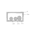
- the first tube 2a and the two second tubes 2b are accommodated in the hollow portion 3a.
- the space factor of all the tubes in the cross section of the hollow portion 3a is 30% or more, the size of the cable bear 3 can be made more compact. Further, there is an advantage that each tube does not dance even when the nozzle device moves.
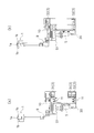
- FIG. 5A is a partial cross-sectional view of the spraying device shown in FIG. 1A taken along the line DD
- FIG. 5B shows the spraying device shown in FIG. It is the fragmentary sectional view cut
- the drive transmission unit 11 and the cable bearer 3 housed in the housing 20 are arranged side by side as described above. At this time, there is a wall between the drive transmission unit 11 and the cable bear 3, and both are installed in different sections. Thereby, when the nozzle device reciprocates, it is possible to prevent the drive transmission unit 11 and the cable bear 3 from interfering with each other.
- the cable bears 3 of the adjacent units U are different from each other in the installed height direction position. That is, with respect to the position in the height direction of the cable bear 31 of one unit U shown in FIG. 5A, the position in the height direction of the cable bear 32 of the other unit U shown in FIG. The side is located above and the bottom is located below. Thereby, even if it is a case where the distance between the nozzle apparatuses 1 of the adjacent unit U is near, it can suppress that the cable bears 3 interfere.
- the spraying device 100 is installed such that the longitudinal direction thereof is parallel to the width direction of the traveling body. Then, the nozzle device 1 of the spraying device 100 sprays the chemical and air on the traveling body while reciprocating in the longitudinal direction.
- medical solution which concerns on this embodiment is provided using the spraying apparatus 100 mentioned above.
- the chemical solution include wet paper strength agents, cleaning agents, pitch control agents, antifouling agents, or mold release agents. Since the spraying device 100 can reliably apply the chemical liquid to the traveling body, the traveling body to which the chemical liquid is applied can reliably exhibit the function based on the applied chemical liquid. For example, when a chemical
- the viscosity of the chemical solution is preferably 500 cps or less, and more preferably 1 to 200 cps.
- the chemical liquid can be reliably applied to the traveling body, and scattering of the chemical liquid can be sufficiently suppressed.
- the spraying device 100 includes the nozzle device 1 that sprays the chemical and air against the traveling body in the paper machine while reciprocating in the longitudinal direction, but the nozzle device is not limited to this structure. .
- the nozzle device may spray only the chemical liquid on the traveling body, or may spray only air.
- the nozzle device sprays only the chemical liquid the effect based on the chemical liquid can be exhibited by applying the chemical liquid to the traveling body.
- the nozzle device blows only air this can be removed by blowing air to the traveling body, for example, by blowing off the attached dust.
- the nozzle unit of the nozzle device only needs to be one place, and the number of tubes for supplying the chemical solution or air may be one.
- the tube accommodated in the cable bear 3 also becomes one.
- the nozzle device 1, the base portion 10, the first tube 2 a, the second tube 2 b, and the cable bear 3 have two units U.
- the spraying device may have only one unit U or may have three or more units. Even when three or more units U are provided, the cable bears 3 are installed so as to overlap in the vertical direction.
- the nozzle device 1 is supported by the first connecting pipe 4a and the second connecting pipe 4b, but the connecting pipe is not necessarily provided. Moreover, although the 1st connection pipe 4a and the 2nd connection pipe 4b are attached to the connection base 9, the connection base 9 does not necessarily need to be provided. That is, the nozzle device may be directly attached to the base portion 10.
- connection base 9 has a proximity sensor attached to the bottom surface thereof, but is not limited thereto, and a limit switch, a tactile switch, or the like may be attached.
- the connecting base 9 is attached to the base 10, but the connecting base 9 is preferably detachable from the base 10. In this case, it is easy to perform maintenance of the detection body S ⁇ b> 1 provided on the connection base 9 by removing the connection base 9 from the base 10.
- the drive transmission unit 11 has a configuration in which an endless metal chain 11a is installed on a pair of gears 11b, but is not limited thereto, a timing belt, a wire, It may consist of a rack, gears, cams and the like.
- the drive unit 12 is a gear drive motor, but is not limited thereto, and may be a cylinder, a linear motor, or the like.
- the spraying device of the present invention is suitably used as a device for applying fluid to a traveling body in a paper machine. According to the spraying device of the present invention, there is an advantage that maintenance is easy.
Landscapes
- Paper (AREA)
- Spray Control Apparatus (AREA)
- Details Or Accessories Of Spraying Plant Or Apparatus (AREA)
Abstract
Description
例えば、ドライヤー表面から5cm以上離して設置された散布装置本体内を走行するスプレーユニットの散布口より吐出圧力により霧化した固体潤滑剤を抄紙機ドライヤー表面にノズルユニットを移動させながらスプレーする散布装置が知られている(例えば、特許文献1参照)。
なお、かかる散布装置は、薬液タンク、付属装置、ケーブルベア、タイミングベルト又はキャタピラチェーンで構成されている。
また、駆動伝達部及びケーブルベアを並設すると散布装置自体もコンパクトにすることができる。
一方、流体がエアーである場合、ノズル装置のノズル部から走行体にエアーを付与することにより、例えば、付着した埃を吹き飛ばして除去することができる。
また、ケーブルベアのメンテナンスの際には、複数のケーブルベアを筐体の端部で一気に取り外すことができる。
このとき、薬液の粘度は、吹付け安定性の観点から、500cps以下であることが好ましい。
本実施形態に係る散布装置は、長手方向に往復移動しながら抄紙機における走行体に対して薬液及びエアーを吹き付けるノズル装置を有する長尺状の装置である。
ここで、走行体としては、例えば、紙体、ワイヤー、フェルト、ドライヤーロール、カンバス、カンバスロール、カレンダーロール等が挙げられる。
図1(a)に示すように、本実施形態に係る散布装置100は、薬液を吹き付けるためのノズル部(以下便宜的に「第1ノズル部」という。)1a及びエアーを吹き付けるためのノズル部(以下便宜的に「第2ノズル部」という。)1bを有するノズル装置1と、第1ノズル部1aにエアーを供給するチューブ(以下便宜的に「第1チューブ」という。)2aと、第2ノズル部1bに薬液を供給するチューブ(以下便宜的に「第2チューブ」という。)2bと、第1チューブ2a及び第2チューブ2bが中空部に収容されたケーブルベア3と、ノズル装置1が取り付けられた基底部10と、該基底部10が取り付けられた駆動伝達部11と、該駆動伝達部11を駆動させる駆動部12と、ケーブルベア3及び駆動伝達部11を収容する長尺状の筐体20とを備える。
そして、隣り合うユニットUの各基底部10は、一定の間隔をおいて駆動伝達部11に取り付けられている。すなわち、ユニットU同士は、ノズル装置の往復移動の際に互いに干渉しないようになっている。
散布装置100によれば、ユニットUを複数備えるので、薬液及びエアーを、走行体に対して効率良く吹き付けることが可能である。
これにより、駆動伝達部11を取り外すことなく、外部からケーブルベア3の状態を目で見て、溜まったゴミの量や劣化具合等を確認することができ、メンテナンスもし易くなっている。
また、駆動伝達部11及びケーブルベア3が並設されているので、散布装置100自体をよりコンパクトにすることができる。
なお、駆動伝達部11及びケーブルベア3の詳細については、後述する。
ここで、第2ノズル部1bは、該第2ノズル部1bから吹き付けられるエアーが、第1ノズル部1aから吹き付けられる薬液を前後から挟み込むように、第1ノズル部1aの前後に一対設けられている。
これにより、ノズル装置1のノズル部1aから吹き付けられた薬液は、前後に吹き付けられるエアーにより、横方向に飛散することが防止される。
そして、ノズル装置1は、一対の第2連結管に支持されている。
第1連結管4a及び第2連結管4bは、連結基部9に取り付けられており、連結基部9は、基底部10に取り付けられている。
すなわち、ノズル装置1は、第1連結管4a及び第2連結管4bと、連結基部9とを介して、基底部10に取り付けられている。
一方で、散布装置100の筐体20長手方向には複数の近接センサーSが設けられている。
したがって、散布装置100においては、当該検出体S1が近接センサーSの上部に来ると、近接センサーSがそれを検知することにより、ノズル装置1の往復移動や停止位置を制御することが可能となっている。
図2に示すように、駆動伝達部11は、エンドレス状の金属製チェーンからなる。具体的には、一対の歯車11bにエンドレス状の金属製チェーン11aが架設された構成となっている。このため、簡単な装置で、ノズル装置の往復移動をスムーズに行うことができる。
そして、駆動伝達部11の金属製チェーン11aには、上述した基底部10が取り付けられている。
したがって、散布装置100においては、駆動部12により、駆動伝達部11が駆動されることになる。具体的には、駆動部12であるギヤ駆動モーターが、歯車11bを回動させることにより、金属製チェーン11aが移動し、金属製チェーン11aに取り付けられた基底部10を介して、ノズル装置1が移動することになる。
なお、当該ギア駆動モーターは、使用温度範囲80度以上であることが好ましい。この場合、作業現場が高温環境下であったとしても、安定した稼働を実現することができる。
筐体20の形状は、直方体状となっている。なお、筐体20は、断面視で矩形型であってもよく、一面を取り除いたU字型又はC字型であってもよい。
ここで、筐体20の左右の側面は、開閉可能な蓋部21となっている。
これにより、駆動伝達部11のメンテナンスを行う際には、蓋部21から駆動伝達部11を取り出すことができる。なお、環状の駆動伝達部11を取り出す場合には、一部を分断することにより、蓋部21から容易に引き出すことができる。
かかるチューブの材質としては、特に限定されないが、耐久性の観点から、フッ素樹脂からなるものであることが好ましい。
また、薬液は、図示しない薬液タンクから、各第2チューブ2b内及び第2連結管4b内を順次流通して、第1ノズル部1aに供給されるようになっている。
図3は、図1(a)に示す散布装置をC-C線で切断した面を示す説明図である。
図3に示すように、散布装置100において、ケーブルベア3は、一端が基底部10に着脱可能となるように取り付けられ、他端が筐体20底面の端部20aに着脱可能となるように固定されている。このため、ケーブルベア3は、ノズル装置11の往復移動に追従して屈曲するようになっている。
このとき、筐体20下面の端部20aには、開閉可能な取出し口20bが設けられていることが好ましい。
また、複数のケーブルベア3同士のメンテナンスの際には、全てのケーブルベアを筐体20の端部20aから一気に取り外すことができる。
図4に示すように、ケーブルベア3においては、上述したように、中空部3aに、第1チューブ2aと、2本の第2チューブ2bが収容されている。
中空部3aの断面における全てのチューブの占積率が30%以上であると、ケーブルベア3のサイズをよりコンパクトにすることができる。また、ノズル装置が移動した場合にも、各チューブが踊らないという利点もある。
図5(a)及び図5(b)に示すように、筐体20に収容されている駆動伝達部11及びケーブルベア3は、上述したように並設されている。
このとき、駆動伝達部11とケーブルベア3との間には、壁があり、両者は、互いに別の区画に設置されている。
これにより、ノズル装置が往復移動する際に、駆動伝達部11及びケーブルベア3が互いに干渉することを防止することができる。
すなわち、図5(a)に示す一方のユニットUのケーブルベア31の高さ方向の位置に対し、図5(b)に示す他方のユニットUのケーブルベア32の高さ方向の位置は、上側が上方に位置し、下側が下方に位置している。
これにより、仮に、隣り合うユニットUのノズル装置1同士の間の距離が近い場合であっても、ケーブルベア3同士が干渉することを抑制することができる。
そして、散布装置100のノズル装置1が長手方向に往復移動しながら走行体に薬液及びエアーを吹き付けることになる。
本実施形態に係る薬液は、上述した散布装置100を用いて付与される。
当該薬液としては、湿潤紙力剤、洗浄剤、ピッチコントロール剤、汚染防止剤又は離型剤等が挙げられる。
散布装置100は、薬液を走行体に確実に付与することができるので、薬液が付与された走行体は、付与される薬液に基づく機能を確実に発揮することができる。例えば、薬液が汚染防止剤である場合、パルプ原料由来の異物が付着することを防止することができ、剥離剤である場合、装置からの湿紙の剥離性を向上させることができる。
ノズル装置が薬液のみを吹き付けるものである場合、走行体に薬液を付与することにより、当該薬液に基づく効果を発揮させることができる。
また、ノズル装置がエアーのみを吹き付けるものである場合、走行体にエアーを付与することにより、例えば、付着した埃を吹き飛ばすことにより、これを除去することができる。
なお、これらの場合、ノズル装置のノズル部は1箇所であればよく、薬液又はエアーを供給するチューブも1本でよい。また、ケーブルベア3に収容されるチューブも1本となる。
なお、ユニットUを3つ以上有する場合であっても、ケーブルベア3同士は、上下方向に重ねて設置される。
また、第1連結管4a及び第2連結管4bは、連結基部9に取り付けられているが、連結基部9は必ずしも設ける必要はない。
すなわち、ノズル装置は、基底部10に直接取り付けられていてもよい。
この場合、連結基部9を基底部10から取り外すことにより、連結基部9に設けられた検出体S1のメンテナンスを行い易い。
1a・・・第1ノズル部(ノズル部)
1b・・・第2ノズル部(ノズル部)
10・・・基底部
100・・・散布装置
11・・・駆動伝達部
11a・・・金属製チェーン
11b・・・歯車
12・・・駆動部
2a・・・第1チューブ(チューブ)
2b・・・第2チューブ(チューブ)
20・・・筐体
20a・・・端部
20b・・・取出し口
21・・・蓋部
3,31,32・・・ケーブルベア(登録商標)
3a・・・中空部
4a・・・第1連結管(連結管)
4b・・・第2連結管(連結管)
9・・・連結基部
S・・・近接センサー
S1・・・検出体
U・・・ユニット
Claims (10)
- 長手方向に往復移動しながら抄紙機における走行体に対して流体を吹き付けるノズル装置を有する長尺状の散布装置であって、
前記流体を吹き付けるためのノズル部を有するノズル装置と、
前記ノズル部に前記流体を供給するチューブと、
前記チューブが中空部に収容されたケーブルベアと、
前記ノズル装置が取り付けられた基底部と、
該基底部が取り付けられた駆動伝達部と、
該駆動伝達部を駆動させる駆動部と、
前記ケーブルベア及び前記駆動伝達部を収容する筐体と、
を備え、
前記駆動伝達部及び前記ケーブルベアが上下方向に重ならないように並設されており、
前記駆動部が前記駆動伝達部を駆動させることにより、前記基底部を介して、前記ノズル装置が移動する散布装置。 - 前記ケーブルベアの一端が前記基底部に着脱可能となるように取り付けられ、他端が前記筐体底面の端部に着脱可能となるように固定されている請求項1記載の散布装置。
- 前記駆動伝達部が、エンドレス状の金属製チェーンである請求項1又は2に記載の散布装置。
- 前記基底部が前記駆動伝達部から着脱可能となっている請求項1~3のいずれか1項に記載の散布装置。
- 前記駆動部が使用温度範囲80度以上のギヤ駆動モーターである請求項1~4のいずれか1項に記載の散布装置。
- 前記ケーブルベアの中空部の断面におけるチューブの占積率が30%以上である請求項1~5のいずれか1項に記載の散布装置。
- 前記ノズル装置と、前記基底部と、前記チューブと、前記ケーブルベアとからなるユニットを複数有し、
複数の前記基底部が前記駆動伝達部に一定の間隔をおいて取り付けられており、
複数の前記ケーブルベア同士が上下方向に重ねて設置されている請求項1~6のいずれか1項に記載の散布装置。 - 前記流体が薬液又はエアーである請求項1~7のいずれか1項に記載の散布装置。
- 請求項1~7のいずれか1項に記載の散布装置を用いて付与され、
該散布装置で吹き付けられる流体が薬液であり、
該薬液が、湿潤紙力剤、洗浄剤、ピッチコントロール剤、汚染防止剤又は離型剤である薬液。 - 粘度が500cps以下である請求項9記載の薬液。
Priority Applications (6)
| Application Number | Priority Date | Filing Date | Title |
|---|---|---|---|
| KR1020177033751A KR20170140308A (ko) | 2015-04-27 | 2016-04-05 | 살포 장치 및 약액 |
| EP16786107.9A EP3290581A4 (en) | 2015-04-27 | 2016-04-05 | Spraying device and chemical solution |
| CA2983778A CA2983778A1 (en) | 2015-04-27 | 2016-04-05 | Spraying apparatus and chemical solution |
| US15/569,718 US20180126402A1 (en) | 2015-04-27 | 2016-04-05 | Spraying apparatus and chemical solution |
| CN201680024265.2A CN107960110A (zh) | 2015-04-27 | 2016-04-05 | 喷洒装置及药液 |
| AU2016255790A AU2016255790A1 (en) | 2015-04-27 | 2016-04-05 | Spraying apparatus and chemical solution |
Applications Claiming Priority (2)
| Application Number | Priority Date | Filing Date | Title |
|---|---|---|---|
| JP2015090883A JP2016204797A (ja) | 2015-04-27 | 2015-04-27 | 散布装置及び薬液 |
| JP2015-090883 | 2015-04-27 |
Publications (1)
| Publication Number | Publication Date |
|---|---|
| WO2016174827A1 true WO2016174827A1 (ja) | 2016-11-03 |
Family
ID=57199100
Family Applications (1)
| Application Number | Title | Priority Date | Filing Date |
|---|---|---|---|
| PCT/JP2016/001918 Ceased WO2016174827A1 (ja) | 2015-04-27 | 2016-04-05 | 散布装置及び薬液 |
Country Status (8)
| Country | Link |
|---|---|
| US (1) | US20180126402A1 (ja) |
| EP (1) | EP3290581A4 (ja) |
| JP (1) | JP2016204797A (ja) |
| KR (1) | KR20170140308A (ja) |
| CN (1) | CN107960110A (ja) |
| AU (1) | AU2016255790A1 (ja) |
| CA (1) | CA2983778A1 (ja) |
| WO (1) | WO2016174827A1 (ja) |
Cited By (1)
| Publication number | Priority date | Publication date | Assignee | Title |
|---|---|---|---|---|
| WO2021235382A1 (ja) * | 2020-05-18 | 2021-11-25 | 株式会社メンテック | 薬液の吹付け方法 |
Families Citing this family (3)
| Publication number | Priority date | Publication date | Assignee | Title |
|---|---|---|---|---|
| KR102047052B1 (ko) * | 2018-06-01 | 2019-11-20 | (주) 즐거운미래 | 제설장비 이동 노즐 시스템 |
| WO2021167099A1 (ja) | 2020-02-21 | 2021-08-26 | 株式会社メンテック | 散布装置 |
| CN111515044A (zh) * | 2020-04-26 | 2020-08-11 | 北京农业智能装备技术研究中心 | 立式禽舍喷雾装置和立式禽舍喷雾方法 |
Citations (5)
| Publication number | Priority date | Publication date | Assignee | Title |
|---|---|---|---|---|
| WO1991003359A1 (en) * | 1989-09-08 | 1991-03-21 | Fibron Machine Corp. | An apparatus for cutting a moving paper sheet by means of a water jet |
| JPH06280181A (ja) * | 1992-09-07 | 1994-10-04 | Mentetsuku:Kk | 抄紙機ドライヤー表面に固体潤滑剤を散布し,表面に潤滑性被 膜を形成させる方法及びそれに用いる薬液散布装置と固体潤滑 剤 |
| JPH09122540A (ja) * | 1995-11-01 | 1997-05-13 | Horikawa Seisakusho:Kk | 流体散布ノズル及びそれを用いた流体散布装置 |
| JP2008018424A (ja) * | 2006-06-16 | 2008-01-31 | Maintech Co Ltd | ノズル装置、それを用いた薬液の付与方法及び薬液 |
| JP2008290023A (ja) * | 2007-05-25 | 2008-12-04 | Maintech Co Ltd | ノズル装置並びにそれを用いた薬液の付与方法及び薬液 |
Family Cites Families (8)
| Publication number | Priority date | Publication date | Assignee | Title |
|---|---|---|---|---|
| JPH11246310A (ja) * | 1998-02-25 | 1999-09-14 | Showa Kk | 殺菌剤 |
| JP3432819B1 (ja) * | 2002-07-31 | 2003-08-04 | 株式会社メンテック | 液体吹付付与装置、それを使用した液体の吹き付け付与方法、及び薬液 |
| CN101495241B (zh) * | 2006-06-16 | 2012-09-19 | 曼泰克株式会社 | 喷嘴装置、使用该喷嘴装置的药液的供给方法 |
| CN102373641A (zh) * | 2010-08-20 | 2012-03-14 | 河南省江河纸业有限责任公司 | 自动全幅循环式高压洗涤喷水器 |
| CN202962745U (zh) * | 2012-11-21 | 2013-06-05 | 西安艾力特电子实业有限公司 | 一种在线式选择性三防漆涂覆机机头三维运动机构 |
| CN203264940U (zh) * | 2013-04-25 | 2013-11-06 | 天津戴卡轮毂制造有限公司 | 铝合金车轮在线喷涂机械手 |
| FR3009794B1 (fr) * | 2013-08-26 | 2020-02-28 | Turner S.A.S. | Machine et procede d'enduction a pulverisateur mobile |
| CN103934140A (zh) * | 2014-04-22 | 2014-07-23 | 南通普瑞特机械有限公司 | 喷漆往复机的喷枪行走机构 |
-
2015
- 2015-04-27 JP JP2015090883A patent/JP2016204797A/ja active Pending
-
2016
- 2016-04-05 EP EP16786107.9A patent/EP3290581A4/en not_active Withdrawn
- 2016-04-05 US US15/569,718 patent/US20180126402A1/en not_active Abandoned
- 2016-04-05 AU AU2016255790A patent/AU2016255790A1/en not_active Abandoned
- 2016-04-05 KR KR1020177033751A patent/KR20170140308A/ko not_active Withdrawn
- 2016-04-05 WO PCT/JP2016/001918 patent/WO2016174827A1/ja not_active Ceased
- 2016-04-05 CA CA2983778A patent/CA2983778A1/en not_active Abandoned
- 2016-04-05 CN CN201680024265.2A patent/CN107960110A/zh active Pending
Patent Citations (5)
| Publication number | Priority date | Publication date | Assignee | Title |
|---|---|---|---|---|
| WO1991003359A1 (en) * | 1989-09-08 | 1991-03-21 | Fibron Machine Corp. | An apparatus for cutting a moving paper sheet by means of a water jet |
| JPH06280181A (ja) * | 1992-09-07 | 1994-10-04 | Mentetsuku:Kk | 抄紙機ドライヤー表面に固体潤滑剤を散布し,表面に潤滑性被 膜を形成させる方法及びそれに用いる薬液散布装置と固体潤滑 剤 |
| JPH09122540A (ja) * | 1995-11-01 | 1997-05-13 | Horikawa Seisakusho:Kk | 流体散布ノズル及びそれを用いた流体散布装置 |
| JP2008018424A (ja) * | 2006-06-16 | 2008-01-31 | Maintech Co Ltd | ノズル装置、それを用いた薬液の付与方法及び薬液 |
| JP2008290023A (ja) * | 2007-05-25 | 2008-12-04 | Maintech Co Ltd | ノズル装置並びにそれを用いた薬液の付与方法及び薬液 |
Non-Patent Citations (1)
| Title |
|---|
| See also references of EP3290581A4 * |
Cited By (1)
| Publication number | Priority date | Publication date | Assignee | Title |
|---|---|---|---|---|
| WO2021235382A1 (ja) * | 2020-05-18 | 2021-11-25 | 株式会社メンテック | 薬液の吹付け方法 |
Also Published As
| Publication number | Publication date |
|---|---|
| AU2016255790A1 (en) | 2017-11-16 |
| JP2016204797A (ja) | 2016-12-08 |
| KR20170140308A (ko) | 2017-12-20 |
| EP3290581A1 (en) | 2018-03-07 |
| CN107960110A (zh) | 2018-04-24 |
| EP3290581A4 (en) | 2018-12-12 |
| CA2983778A1 (en) | 2016-11-03 |
| US20180126402A1 (en) | 2018-05-10 |
Similar Documents
| Publication | Publication Date | Title |
|---|---|---|
| WO2016174827A1 (ja) | 散布装置及び薬液 | |
| KR20150074994A (ko) | 배관 이물질 청소장치 | |
| AU2019210563B2 (en) | Canvas cleaning device, canvas cleaning method and canvas cleaning mechanism | |
| JP2012510005A5 (ja) | ||
| ATE544709T1 (de) | Verfahren und vorrichtung zum wellen und abwickeln von plastikfolienrollen | |
| EP1964794A3 (en) | Device for cleaning from a conveyor belt, driven on rollers, fluid substances sprayed thereon | |
| ITVI20070235A1 (it) | Macchina perfezionata per la pulizia di superfici laminari flessibili. | |
| WO2015029108A1 (ja) | 汚れ除去装置および除去方法 | |
| CN109843448B (zh) | 喷嘴腔室的结构 | |
| CN106133240B (zh) | 药液的喷涂方法 | |
| CN106388719A (zh) | 拖地机构 | |
| JP6644016B2 (ja) | カンバス洗浄装置 | |
| CN118926249B (zh) | 一种防破损显示屏玻璃自动清洗设备 | |
| US20090266388A1 (en) | Flexible showering device for a pulp and paper making machine | |
| WO2021167099A1 (ja) | 散布装置 | |
| FI20011549L (fi) | Laitteisto nesteen poistamiseksi kuituainerainasta | |
| US8672019B1 (en) | Cleaning unit for a continuous metal strip as well as a strip casting installation with such a cleaning unit | |
| KR101698477B1 (ko) | 드립 팬 유지보수장치 및 드립 팬 유지보수방법 | |
| FI115312B (fi) | Puhdistuslaitteisto paperin tai kartongin viimeistelylaitetta varten | |
| CN210614443U (zh) | 不锈钢卷材表面连续清洁设备 | |
| CN205062568U (zh) | 用于连续运行的刮除设备的刮刀 | |
| JP4733569B2 (ja) | 連続洗浄装置及びこれを用いた連続洗浄方法 | |
| CN206946869U (zh) | 方便清理的落地灯箱 | |
| DE112006001686A5 (de) | Vorrichtung zum Abquetschen von Tränkflüssigkeit aus einer Stoffbahn | |
| FI20065164A7 (fi) | Menetelmä ja pesulaite rainanmuodostuskoneen leveyssuuntaisen elimen pesemiseksi sekä pesulaite teräpitimen pesemiseksi |
Legal Events
| Date | Code | Title | Description |
|---|---|---|---|
| 121 | Ep: the epo has been informed by wipo that ep was designated in this application |
Ref document number: 16786107 Country of ref document: EP Kind code of ref document: A1 |
|
| ENP | Entry into the national phase |
Ref document number: 2983778 Country of ref document: CA |
|
| WWE | Wipo information: entry into national phase |
Ref document number: 15569718 Country of ref document: US |
|
| NENP | Non-entry into the national phase |
Ref country code: DE |
|
| ENP | Entry into the national phase |
Ref document number: 2016255790 Country of ref document: AU Date of ref document: 20160405 Kind code of ref document: A |
|
| ENP | Entry into the national phase |
Ref document number: 20177033751 Country of ref document: KR Kind code of ref document: A |