WO2016174866A1 - 化学物質濃縮器 - Google Patents
化学物質濃縮器 Download PDFInfo
- Publication number
- WO2016174866A1 WO2016174866A1 PCT/JP2016/002192 JP2016002192W WO2016174866A1 WO 2016174866 A1 WO2016174866 A1 WO 2016174866A1 JP 2016002192 W JP2016002192 W JP 2016002192W WO 2016174866 A1 WO2016174866 A1 WO 2016174866A1
- Authority
- WO
- WIPO (PCT)
- Prior art keywords
- chemical substance
- adsorption
- substance concentrator
- portions
- concentrator according
- Prior art date
- Legal status (The legal status is an assumption and is not a legal conclusion. Google has not performed a legal analysis and makes no representation as to the accuracy of the status listed.)
- Ceased
Links
Images






Classifications
-
- G—PHYSICS
- G01—MEASURING; TESTING
- G01N—INVESTIGATING OR ANALYSING MATERIALS BY DETERMINING THEIR CHEMICAL OR PHYSICAL PROPERTIES
- G01N1/00—Sampling; Preparing specimens for investigation
- G01N1/28—Preparing specimens for investigation including physical details of (bio-)chemical methods covered elsewhere, e.g. G01N33/50, C12Q
- G01N1/40—Concentrating samples
- G01N1/405—Concentrating samples by adsorption or absorption
-
- B—PERFORMING OPERATIONS; TRANSPORTING
- B01—PHYSICAL OR CHEMICAL PROCESSES OR APPARATUS IN GENERAL
- B01D—SEPARATION
- B01D53/00—Separation of gases or vapours; Recovering vapours of volatile solvents from gases; Chemical or biological purification of waste gases, e.g. engine exhaust gases, smoke, fumes, flue gases, aerosols
- B01D53/02—Separation of gases or vapours; Recovering vapours of volatile solvents from gases; Chemical or biological purification of waste gases, e.g. engine exhaust gases, smoke, fumes, flue gases, aerosols by adsorption, e.g. preparative gas chromatography
- B01D53/04—Separation of gases or vapours; Recovering vapours of volatile solvents from gases; Chemical or biological purification of waste gases, e.g. engine exhaust gases, smoke, fumes, flue gases, aerosols by adsorption, e.g. preparative gas chromatography with stationary adsorbents
- B01D53/0407—Constructional details of adsorbing systems
-
- B—PERFORMING OPERATIONS; TRANSPORTING
- B01—PHYSICAL OR CHEMICAL PROCESSES OR APPARATUS IN GENERAL
- B01D—SEPARATION
- B01D53/00—Separation of gases or vapours; Recovering vapours of volatile solvents from gases; Chemical or biological purification of waste gases, e.g. engine exhaust gases, smoke, fumes, flue gases, aerosols
- B01D53/02—Separation of gases or vapours; Recovering vapours of volatile solvents from gases; Chemical or biological purification of waste gases, e.g. engine exhaust gases, smoke, fumes, flue gases, aerosols by adsorption, e.g. preparative gas chromatography
- B01D53/04—Separation of gases or vapours; Recovering vapours of volatile solvents from gases; Chemical or biological purification of waste gases, e.g. engine exhaust gases, smoke, fumes, flue gases, aerosols by adsorption, e.g. preparative gas chromatography with stationary adsorbents
-
- B—PERFORMING OPERATIONS; TRANSPORTING
- B01—PHYSICAL OR CHEMICAL PROCESSES OR APPARATUS IN GENERAL
- B01D—SEPARATION
- B01D53/00—Separation of gases or vapours; Recovering vapours of volatile solvents from gases; Chemical or biological purification of waste gases, e.g. engine exhaust gases, smoke, fumes, flue gases, aerosols
- B01D53/02—Separation of gases or vapours; Recovering vapours of volatile solvents from gases; Chemical or biological purification of waste gases, e.g. engine exhaust gases, smoke, fumes, flue gases, aerosols by adsorption, e.g. preparative gas chromatography
- B01D53/04—Separation of gases or vapours; Recovering vapours of volatile solvents from gases; Chemical or biological purification of waste gases, e.g. engine exhaust gases, smoke, fumes, flue gases, aerosols by adsorption, e.g. preparative gas chromatography with stationary adsorbents
- B01D53/0407—Constructional details of adsorbing systems
- B01D53/0438—Cooling or heating systems
-
- B—PERFORMING OPERATIONS; TRANSPORTING
- B01—PHYSICAL OR CHEMICAL PROCESSES OR APPARATUS IN GENERAL
- B01J—CHEMICAL OR PHYSICAL PROCESSES, e.g. CATALYSIS OR COLLOID CHEMISTRY; THEIR RELEVANT APPARATUS
- B01J20/00—Solid sorbent compositions or filter aid compositions; Sorbents for chromatography; Processes for preparing, regenerating or reactivating thereof
- B01J20/02—Solid sorbent compositions or filter aid compositions; Sorbents for chromatography; Processes for preparing, regenerating or reactivating thereof comprising inorganic material
- B01J20/06—Solid sorbent compositions or filter aid compositions; Sorbents for chromatography; Processes for preparing, regenerating or reactivating thereof comprising inorganic material comprising oxides or hydroxides of metals not provided for in group B01J20/04
-
- B—PERFORMING OPERATIONS; TRANSPORTING
- B01—PHYSICAL OR CHEMICAL PROCESSES OR APPARATUS IN GENERAL
- B01J—CHEMICAL OR PHYSICAL PROCESSES, e.g. CATALYSIS OR COLLOID CHEMISTRY; THEIR RELEVANT APPARATUS
- B01J20/00—Solid sorbent compositions or filter aid compositions; Sorbents for chromatography; Processes for preparing, regenerating or reactivating thereof
- B01J20/02—Solid sorbent compositions or filter aid compositions; Sorbents for chromatography; Processes for preparing, regenerating or reactivating thereof comprising inorganic material
- B01J20/20—Solid sorbent compositions or filter aid compositions; Sorbents for chromatography; Processes for preparing, regenerating or reactivating thereof comprising inorganic material comprising free carbon; comprising carbon obtained by carbonising processes
- B01J20/205—Carbon nanostructures, e.g. nanotubes, nanohorns, nanocones, nanoballs
-
- B—PERFORMING OPERATIONS; TRANSPORTING
- B01—PHYSICAL OR CHEMICAL PROCESSES OR APPARATUS IN GENERAL
- B01J—CHEMICAL OR PHYSICAL PROCESSES, e.g. CATALYSIS OR COLLOID CHEMISTRY; THEIR RELEVANT APPARATUS
- B01J20/00—Solid sorbent compositions or filter aid compositions; Sorbents for chromatography; Processes for preparing, regenerating or reactivating thereof
- B01J20/28—Solid sorbent compositions or filter aid compositions; Sorbents for chromatography; Processes for preparing, regenerating or reactivating thereof characterised by their form or physical properties
- B01J20/28014—Solid sorbent compositions or filter aid compositions; Sorbents for chromatography; Processes for preparing, regenerating or reactivating thereof characterised by their form or physical properties characterised by their form
- B01J20/28023—Fibres or filaments
-
- G—PHYSICS
- G01—MEASURING; TESTING
- G01N—INVESTIGATING OR ANALYSING MATERIALS BY DETERMINING THEIR CHEMICAL OR PHYSICAL PROPERTIES
- G01N1/00—Sampling; Preparing specimens for investigation
- G01N1/02—Devices for withdrawing samples
- G01N1/22—Devices for withdrawing samples in the gaseous state
-
- G—PHYSICS
- G01—MEASURING; TESTING
- G01N—INVESTIGATING OR ANALYSING MATERIALS BY DETERMINING THEIR CHEMICAL OR PHYSICAL PROPERTIES
- G01N1/00—Sampling; Preparing specimens for investigation
- G01N1/02—Devices for withdrawing samples
- G01N1/22—Devices for withdrawing samples in the gaseous state
- G01N1/2202—Devices for withdrawing samples in the gaseous state involving separation of sample components during sampling
- G01N1/2214—Devices for withdrawing samples in the gaseous state involving separation of sample components during sampling by sorption
-
- G—PHYSICS
- G01—MEASURING; TESTING
- G01N—INVESTIGATING OR ANALYSING MATERIALS BY DETERMINING THEIR CHEMICAL OR PHYSICAL PROPERTIES
- G01N1/00—Sampling; Preparing specimens for investigation
- G01N1/02—Devices for withdrawing samples
- G01N1/22—Devices for withdrawing samples in the gaseous state
- G01N1/2247—Sampling from a flowing stream of gas
-
- G—PHYSICS
- G01—MEASURING; TESTING
- G01N—INVESTIGATING OR ANALYSING MATERIALS BY DETERMINING THEIR CHEMICAL OR PHYSICAL PROPERTIES
- G01N27/00—Investigating or analysing materials by the use of electric, electrochemical, or magnetic means
- G01N27/02—Investigating or analysing materials by the use of electric, electrochemical, or magnetic means by investigating impedance
- G01N27/04—Investigating or analysing materials by the use of electric, electrochemical, or magnetic means by investigating impedance by investigating resistance
- G01N27/12—Investigating or analysing materials by the use of electric, electrochemical, or magnetic means by investigating impedance by investigating resistance of a solid body in dependence upon absorption of a fluid; of a solid body in dependence upon reaction with a fluid, for detecting components in the fluid
- G01N27/125—Composition of the body, e.g. the composition of its sensitive layer
-
- B—PERFORMING OPERATIONS; TRANSPORTING
- B01—PHYSICAL OR CHEMICAL PROCESSES OR APPARATUS IN GENERAL
- B01D—SEPARATION
- B01D2253/00—Adsorbents used in seperation treatment of gases and vapours
- B01D2253/10—Inorganic adsorbents
- B01D2253/102—Carbon
-
- B—PERFORMING OPERATIONS; TRANSPORTING
- B01—PHYSICAL OR CHEMICAL PROCESSES OR APPARATUS IN GENERAL
- B01D—SEPARATION
- B01D2253/00—Adsorbents used in seperation treatment of gases and vapours
- B01D2253/10—Inorganic adsorbents
- B01D2253/106—Silica or silicates
- B01D2253/108—Zeolites
-
- B—PERFORMING OPERATIONS; TRANSPORTING
- B01—PHYSICAL OR CHEMICAL PROCESSES OR APPARATUS IN GENERAL
- B01D—SEPARATION
- B01D2253/00—Adsorbents used in seperation treatment of gases and vapours
- B01D2253/10—Inorganic adsorbents
- B01D2253/112—Metals or metal compounds not provided for in B01D2253/104 or B01D2253/106
- B01D2253/1122—Metals
-
- B—PERFORMING OPERATIONS; TRANSPORTING
- B01—PHYSICAL OR CHEMICAL PROCESSES OR APPARATUS IN GENERAL
- B01D—SEPARATION
- B01D2253/00—Adsorbents used in seperation treatment of gases and vapours
- B01D2253/10—Inorganic adsorbents
- B01D2253/112—Metals or metal compounds not provided for in B01D2253/104 or B01D2253/106
- B01D2253/1124—Metal oxides
-
- B—PERFORMING OPERATIONS; TRANSPORTING
- B01—PHYSICAL OR CHEMICAL PROCESSES OR APPARATUS IN GENERAL
- B01D—SEPARATION
- B01D2253/00—Adsorbents used in seperation treatment of gases and vapours
- B01D2253/20—Organic adsorbents
- B01D2253/202—Polymeric adsorbents
-
- B—PERFORMING OPERATIONS; TRANSPORTING
- B01—PHYSICAL OR CHEMICAL PROCESSES OR APPARATUS IN GENERAL
- B01D—SEPARATION
- B01D2253/00—Adsorbents used in seperation treatment of gases and vapours
- B01D2253/30—Physical properties of adsorbents
- B01D2253/302—Dimensions
- B01D2253/304—Linear dimensions, e.g. particle shape, diameter
-
- B—PERFORMING OPERATIONS; TRANSPORTING
- B01—PHYSICAL OR CHEMICAL PROCESSES OR APPARATUS IN GENERAL
- B01D—SEPARATION
- B01D2253/00—Adsorbents used in seperation treatment of gases and vapours
- B01D2253/30—Physical properties of adsorbents
- B01D2253/34—Specific shapes
-
- B—PERFORMING OPERATIONS; TRANSPORTING
- B01—PHYSICAL OR CHEMICAL PROCESSES OR APPARATUS IN GENERAL
- B01D—SEPARATION
- B01D2255/00—Catalysts
- B01D2255/10—Noble metals or compounds thereof
- B01D2255/102—Platinum group metals
- B01D2255/1023—Palladium
-
- B—PERFORMING OPERATIONS; TRANSPORTING
- B01—PHYSICAL OR CHEMICAL PROCESSES OR APPARATUS IN GENERAL
- B01D—SEPARATION
- B01D2255/00—Catalysts
- B01D2255/10—Noble metals or compounds thereof
- B01D2255/104—Silver
-
- B—PERFORMING OPERATIONS; TRANSPORTING
- B01—PHYSICAL OR CHEMICAL PROCESSES OR APPARATUS IN GENERAL
- B01D—SEPARATION
- B01D2255/00—Catalysts
- B01D2255/20—Metals or compounds thereof
- B01D2255/207—Transition metals
- B01D2255/20707—Titanium
-
- B—PERFORMING OPERATIONS; TRANSPORTING
- B01—PHYSICAL OR CHEMICAL PROCESSES OR APPARATUS IN GENERAL
- B01D—SEPARATION
- B01D2255/00—Catalysts
- B01D2255/20—Metals or compounds thereof
- B01D2255/207—Transition metals
- B01D2255/20753—Nickel
-
- B—PERFORMING OPERATIONS; TRANSPORTING
- B01—PHYSICAL OR CHEMICAL PROCESSES OR APPARATUS IN GENERAL
- B01D—SEPARATION
- B01D2255/00—Catalysts
- B01D2255/20—Metals or compounds thereof
- B01D2255/207—Transition metals
- B01D2255/20761—Copper
-
- B—PERFORMING OPERATIONS; TRANSPORTING
- B01—PHYSICAL OR CHEMICAL PROCESSES OR APPARATUS IN GENERAL
- B01D—SEPARATION
- B01D2255/00—Catalysts
- B01D2255/20—Metals or compounds thereof
- B01D2255/207—Transition metals
- B01D2255/20769—Molybdenum
-
- B—PERFORMING OPERATIONS; TRANSPORTING
- B01—PHYSICAL OR CHEMICAL PROCESSES OR APPARATUS IN GENERAL
- B01D—SEPARATION
- B01D2255/00—Catalysts
- B01D2255/20—Metals or compounds thereof
- B01D2255/207—Transition metals
- B01D2255/20792—Zinc
-
- B—PERFORMING OPERATIONS; TRANSPORTING
- B01—PHYSICAL OR CHEMICAL PROCESSES OR APPARATUS IN GENERAL
- B01D—SEPARATION
- B01D2255/00—Catalysts
- B01D2255/20—Metals or compounds thereof
- B01D2255/209—Other metals
-
- B—PERFORMING OPERATIONS; TRANSPORTING
- B01—PHYSICAL OR CHEMICAL PROCESSES OR APPARATUS IN GENERAL
- B01D—SEPARATION
- B01D2255/00—Catalysts
- B01D2255/20—Metals or compounds thereof
- B01D2255/209—Other metals
- B01D2255/2094—Tin
-
- B—PERFORMING OPERATIONS; TRANSPORTING
- B01—PHYSICAL OR CHEMICAL PROCESSES OR APPARATUS IN GENERAL
- B01D—SEPARATION
- B01D2255/00—Catalysts
- B01D2255/30—Silica
-
- B—PERFORMING OPERATIONS; TRANSPORTING
- B01—PHYSICAL OR CHEMICAL PROCESSES OR APPARATUS IN GENERAL
- B01D—SEPARATION
- B01D2257/00—Components to be removed
- B01D2257/10—Single element gases other than halogens
- B01D2257/108—Hydrogen
-
- B—PERFORMING OPERATIONS; TRANSPORTING
- B01—PHYSICAL OR CHEMICAL PROCESSES OR APPARATUS IN GENERAL
- B01D—SEPARATION
- B01D2257/00—Components to be removed
- B01D2257/20—Halogens or halogen compounds
- B01D2257/202—Single element halogens
- B01D2257/2025—Chlorine
-
- B—PERFORMING OPERATIONS; TRANSPORTING
- B01—PHYSICAL OR CHEMICAL PROCESSES OR APPARATUS IN GENERAL
- B01D—SEPARATION
- B01D2257/00—Components to be removed
- B01D2257/40—Nitrogen compounds
- B01D2257/404—Nitrogen oxides other than dinitrogen oxide
-
- B—PERFORMING OPERATIONS; TRANSPORTING
- B01—PHYSICAL OR CHEMICAL PROCESSES OR APPARATUS IN GENERAL
- B01D—SEPARATION
- B01D2257/00—Components to be removed
- B01D2257/40—Nitrogen compounds
- B01D2257/406—Ammonia
-
- B—PERFORMING OPERATIONS; TRANSPORTING
- B01—PHYSICAL OR CHEMICAL PROCESSES OR APPARATUS IN GENERAL
- B01D—SEPARATION
- B01D2257/00—Components to be removed
- B01D2257/50—Carbon oxides
- B01D2257/502—Carbon monoxide
-
- B—PERFORMING OPERATIONS; TRANSPORTING
- B01—PHYSICAL OR CHEMICAL PROCESSES OR APPARATUS IN GENERAL
- B01D—SEPARATION
- B01D2257/00—Components to be removed
- B01D2257/70—Organic compounds not provided for in groups B01D2257/00 - B01D2257/602
- B01D2257/708—Volatile organic compounds V.O.C.'s
-
- B—PERFORMING OPERATIONS; TRANSPORTING
- B01—PHYSICAL OR CHEMICAL PROCESSES OR APPARATUS IN GENERAL
- B01D—SEPARATION
- B01D2257/00—Components to be removed
- B01D2257/80—Water
-
- B—PERFORMING OPERATIONS; TRANSPORTING
- B01—PHYSICAL OR CHEMICAL PROCESSES OR APPARATUS IN GENERAL
- B01D—SEPARATION
- B01D2259/00—Type of treatment
- B01D2259/40—Further details for adsorption processes and devices
- B01D2259/40083—Regeneration of adsorbents in processes other than pressure or temperature swing adsorption
-
- B—PERFORMING OPERATIONS; TRANSPORTING
- B01—PHYSICAL OR CHEMICAL PROCESSES OR APPARATUS IN GENERAL
- B01D—SEPARATION
- B01D2259/00—Type of treatment
- B01D2259/40—Further details for adsorption processes and devices
- B01D2259/40083—Regeneration of adsorbents in processes other than pressure or temperature swing adsorption
- B01D2259/40088—Regeneration of adsorbents in processes other than pressure or temperature swing adsorption by heating
- B01D2259/40096—Regeneration of adsorbents in processes other than pressure or temperature swing adsorption by heating by using electrical resistance heating
-
- B—PERFORMING OPERATIONS; TRANSPORTING
- B01—PHYSICAL OR CHEMICAL PROCESSES OR APPARATUS IN GENERAL
- B01D—SEPARATION
- B01D2259/00—Type of treatment
- B01D2259/40—Further details for adsorption processes and devices
- B01D2259/40083—Regeneration of adsorbents in processes other than pressure or temperature swing adsorption
- B01D2259/40088—Regeneration of adsorbents in processes other than pressure or temperature swing adsorption by heating
- B01D2259/40098—Regeneration of adsorbents in processes other than pressure or temperature swing adsorption by heating with other heating means
-
- B—PERFORMING OPERATIONS; TRANSPORTING
- B01—PHYSICAL OR CHEMICAL PROCESSES OR APPARATUS IN GENERAL
- B01D—SEPARATION
- B01D2259/00—Type of treatment
- B01D2259/40—Further details for adsorption processes and devices
- B01D2259/414—Further details for adsorption processes and devices using different types of adsorbents
Definitions
- the present disclosure relates to a chemical substance concentrator that can concentrate volatile organic compounds in a sample.
- Exhaust gas, air, exhaled air, etc. contain volatile organic compounds (VOC).
- VOC volatile organic compounds
- a conventional detection system that detects a volatile organic compound contained in a sample, the volatile organic compound is adsorbed by an adsorption unit. Thereafter, the detection system desorbs the volatile organic compound from the adsorption unit. The detached volatile organic compound is detected by the detection unit.
- Patent Document 1 is known as a prior document relating to the above-described conventional detection system.
- the chemical substance concentrator includes a cylinder and a plurality of adsorbing portions provided at predetermined intervals on a surface facing the inside of the cylinder.
- the chemical concentrator can easily pass the sample.
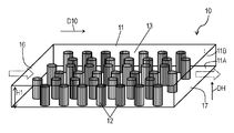
- FIG. 1 is a perspective perspective view schematically showing a chemical substance concentrator in an embodiment.
- FIG. 2 is a top perspective view schematically showing the chemical substance concentrator in the embodiment.
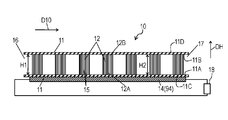
- 3A is a cross-sectional view of the chemical substance concentrator shown in FIG. 2 taken along line 3A-3A.
- 3B is a cross-sectional view of the chemical substance concentrator shown in FIG. 2 taken along line 3B-3B.
- FIG. 3C is an enlarged view of the chemical substance concentrator in the embodiment.
- FIG. 4A is a side cross-sectional view schematically showing another chemical substance concentrator in the embodiment.
- FIG. 4B is a side sectional view schematically showing still another chemical substance concentrator in the embodiment.
- FIG. 4C is a side sectional view schematically showing still another chemical substance concentrator in the embodiment.
- FIG. 4D is a side sectional view schematically showing still another chemical substance concentrator in the embodiment.
- FIG. 4E is a side sectional view schematically showing still another chemical substance concentrator in the embodiment.
- FIG. 4F is a side sectional view schematically showing still another chemical substance concentrator in the embodiment.
- FIG. 4G is a top perspective view schematically showing still another chemical substance concentrator in the embodiment.
- FIG. 4H is a top perspective view schematically showing still another chemical substance concentrator in the embodiment.
- FIG. 5 is a side sectional view schematically showing still another chemical substance concentrator in the embodiment.
- FIG. 6 is a side sectional view schematically showing still another chemical substance concentrator in the embodiment.
- FIG. 7 is a side sectional view schematically showing still another chemical substance concentrator in the embodiment.
- FIG. 8 is a side sectional view schematically showing still another chemical substance concentrator in the embodiment.
- FIG. 1 is a perspective perspective view schematically showing a chemical substance concentrator 10 according to an embodiment.
- FIG. 2 is a top perspective view schematically showing the inside of the chemical substance concentrator 10.
- 3A is a schematic cross-sectional view taken along line 3A-3A of chemical substance concentrator 10 shown in FIG.
- FIG. 3B is a schematic cross-sectional view taken along line 3B-3B of the chemical substance concentrator 10 shown in FIG.
- the chemical substance concentrator 10 adsorbs molecules of chemical substances contained in the sample.
- the sample is, for example, a gas such as exhaust gas, living space air, or human breath.
- the chemical substance is, for example, a volatile organic compound (VOC).
- the chemical substance concentrator 10 includes a cylindrical body 11, an adsorption unit 12, and a desorption mechanism 94.
- the cylinder 11 has an inlet 16 for taking the sample into the cylinder 11 and an outlet 17 for discharging the sample to the outside of the cylinder 11.
- a flow path 13 is formed through which the sample flows from the inlet 16 to the outlet 17 in the flow direction D10.
- the cylindrical body 11 can use various shapes, such as a cylinder and a square tube, for example.
- the cross section of the cylinder 11 shown in FIG. 1 has a quadrangular shape.
- the cylindrical body 11 has inner surfaces 11A, 11B facing each other, an outer surface 11C opposite to the inner surface 11A, and an outer surface 11D opposite to the inner surface 11B.
- the inner surfaces 11 ⁇ / b> A and 11 ⁇ / b> B constitute a flow path 13.
- the width W of the cross section of the flow path 13 is 1 mm, and the height H1 is 30 ⁇ m.
- the length L of the flow path 13 is 10 mm.
- the cylinder 11 is made of an insulator, or made of a material whose surface facing the flow path 13 is covered with an insulator.
- the cylinder 11 is made of, for example, an insulator such as glass, quartz, sapphire, or ceramic, or a silicon substrate on which thermally oxidized silicon is formed.
- the inner surfaces 11A and 11B of the cylinder 11 may be formed of different materials. In that case, the member forming the cylinder 11 may be exposed from either the inner surface 11A or the inner surface 11B.
- the adsorption unit 12 adsorbs chemical molecules contained in the sample.
- a plurality of suction portions 12 are provided on the inner surface 11A of the cylindrical body 11 with a predetermined interval B1 therebetween.
- the adsorption part 12 has a cylindrical shape.
- the adsorption part 12 has an end part 12A fixed to the inner surface 11A of the cylindrical body 11 and an end part 12B opposite to the end part 12A.
- the end 12 ⁇ / b> B is provided and fixed on the inner surface 11 ⁇ / b> B of the cylinder 11.
- FIG. 3C is an enlarged view of the chemical substance concentrator 10 and shows the periphery of the adsorption unit 12.
- the adsorption part 12 is composed of a plurality of dense fibers 15. By forming the adsorption part 12 with a plurality of fibers 15, the surface area of the adsorption part 12 can be increased.
- the sample A10 contains a medium B10 that is a gas and a chemical molecule C10 that floats on the medium B10. Since the adsorbing part 12 is an aggregate of the fibers 15, it has an uneven surface and adsorbs the chemical molecule C10 while entraining the gaseous sample A10 (medium B10) as shown in FIG. 3C. it can.
- the interval B ⁇ b> 1 (see FIG. 2) between the adsorbing portions 12 adjacent to each other is larger than the interval D ⁇ b> 15 between the fibers 15.
- the fiber 15 has anisotropy.
- the fiber 15 is grown using a vapor phase method or a liquid phase method after forming a layer for controlling the growth direction of the fiber 15, a material layer serving as a nucleus of the fiber 15, and a catalyst layer on the inner surface 11 ⁇ / b> A.
- the fibers 15 are preferentially oriented in a direction substantially perpendicular to the inner surface 11A.
- the fiber 15 is made of, for example, a metal such as ZnO, SnO 2 , In 2 O 3 , In 2 ⁇ x Sn x O 3 (for example, 0.1 ⁇ x ⁇ 0.2), NiO, CuO, TiO 2 , and SiO 2. It is formed of an oxide. By causing interaction between oxygen on the surface of the metal oxide and molecules of the chemical substance, the molecules of the chemical substance can be adsorbed efficiently.
- the fiber 15 is a nanowire or a nanofiber.
- the fiber 15 is covered with an adsorbent 115 that selectively adsorbs chemical molecules.
- nickel or silver when carbon monoxide is selectively adsorbed, nickel or silver can be used as the adsorbent 115.
- molybdenum when adsorbing ammonia or chlorine, molybdenum can be used as the adsorbent 115.
- zeolite When adsorbing nitrogen oxides, zeolite can be used as the adsorbent 115.
- palladium can be used as the adsorbent 115.
- polyaniline When water is adsorbed, polyaniline can be used as the adsorbent 115.
- adsorbing molecules of a polar organic substance polyethylene glycol, PDMS (polydimethylsiloxane), or the like can be used as the adsorbent 115.
- the adsorbent 115 is preferably made of a material having a surface having the same polarity as the polarity of the molecular plane.
- the adsorbent 115 can be appropriately selected according to the molecule of the chemical substance to be adsorbed.
- the fiber 15 may be formed of an adsorbent 115 that selectively adsorbs chemical substances.
- the fibers 15 forming the adsorption unit 12 adsorb molecules of chemical substances, the fibers 15 may not be covered with the adsorbent 115.
- the average diameter of the adsorption part 12 is several tens of ⁇ m or more and several hundreds of ⁇ m or less.
- the average diameter D1 of the suction part 12 in the first embodiment shown in FIG. 2 is about 200 ⁇ m.
- the adsorption part 112 of the plurality of adsorption parts 12 is arranged with an interval B1 of about 200 ⁇ m from the adsorption part 212 adjacent to the adsorption part 112 of the plurality of adsorption parts 12.
- the plurality of suction portions 12 are alternately arranged so that the centers 12C of the suction portions 12 located close to each other in the flow direction D10 do not overlap.
- the plurality of adsorbing units 12 are alternately arranged so that the centers 12C of the adsorbing units 12 adjacent to each other in the flow direction D10 do not overlap.
- the sample passes between the plurality of adsorption parts 12 and flows from the inlet 16 to the outlet 17 in the flow direction D10. At this time, the sample is unlikely to flow between the plurality of fibers 15 in one adsorption part 12. This is because the plurality of fibers 15 are densely packed in one adsorption part 12, and the pressure loss in the adsorption part 12 is about 3 to 4 digits larger than the pressure loss between the plurality of adsorption parts 12. is there.
- the height H2 of the suction portion 12 in the height direction DH from the inner surface 11A toward the inner surface 11B is 30 ⁇ m.
- the suction part 12 extends from the inner surface 11A to the inner surface 11B. That is, the height H1 of the flow path 13 in the height direction DH is equal to the height H2 of the suction portion 12, and is 30 ⁇ m in the first embodiment.
- a desorption mechanism 94 is provided on the outer surface 11C opposite to the inner surface 11A. By operating the desorption mechanism 94, the molecules of the chemical substance adsorbed on the adsorption unit 12 are desorbed from the adsorption unit 12 into the sample. Thereby, the chemical substance concentrator 10 can concentrate the chemical substance contained in the sample.
- the desorbed chemical substance molecule is detected by, for example, a detection sensor provided downstream of the chemical substance concentrator 10 in the flow direction D10. Further, the adsorption unit 12 can recover the adsorption function by desorbing the molecules of the adsorbed chemical substance.
- the desorption mechanism 94 is a heating unit 14 that is connected to the external power source 18 and heats the plurality of adsorption units 12.
- the heating unit 14 in the first embodiment is made of a metal wire, a wiring pattern of a resistance heating material, or the like.
- the heating unit 14 may be formed of a thin film made of NiCr processed into a meander shape.
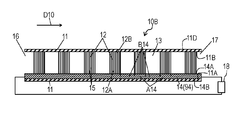
- FIG. 4A is a cross-sectional view of another chemical substance concentrator 10A in the embodiment.
- the same reference numerals are assigned to the same parts as those in the chemical substance concentrator 10 shown in FIGS. 1 to 3C.
- the heating unit 14 that is the desorption mechanism 94 is provided inside the cylinder 11. Specifically, the heating unit 14 is provided between each of the plurality of adsorption units 12 and the cylindrical body 11. An insulating layer 20 is provided between each of the plurality of adsorption units 12 and the heating unit 14. Thereby, the current flowing through the heating unit 14 does not flow into the adsorption unit 12. Therefore, the heating unit 14 can efficiently heat the adsorption unit 12.
- the heating unit 14 has opposite surfaces 14A and 14B.
- the insulating layer 20 has opposite surfaces 20A and 20B.
- the surface 14 ⁇ / b> B of the heating unit 14 is provided on the inner surface 11 ⁇ / b> A of the cylindrical body 11.
- the surface 20B of the insulating layer 20 is provided on the surface 14A of the heating unit 14.
- the surface 20A of the insulating layer 20 faces the flow path 13.
- the end 12 ⁇ / b> A of the adsorption unit 12 is provided on the surface 20 ⁇ / b> A of the insulating layer 20.
- the insulating layer 20 is very thin, and the adsorption unit 12 is substantially in contact with the heating unit 14.
- FIG. 4B is a cross-sectional view of still another chemical substance concentrator 10B in the embodiment.
- the chemical substance concentrator 10B shown in FIG. 4B does not include the insulating layer 20 of the chemical substance concentrator 10A shown in FIG. 4A.
- the adsorption unit 12 has an insulating property.
- a surface 14 ⁇ / b> A of the heating unit 14 faces the flow path 13.
- the end portions 12 ⁇ / b> A of the plurality of adsorption units 12 are provided in the heating unit 14.
- suction part 12 does not need to have insulation.
- the adsorbing portion 12 made of the aggregate of fibers 15 has a small heat capacity due to its structure, the adsorbing portion 12 is in contact with the heating portion 14 in the chemical substance concentrators 10A and 10B shown in FIGS. 4A and 4B. By being substantially in contact with each other, it is efficiently heated and the adsorbed molecule C10 can be desorbed. Thereby, the adsorption
- the heating unit 14 may be made of a heat generating material such as a metal wire or a resistance heating material.
- the heating unit 14 includes a plurality of heating portions A14 that respectively face the plurality of adsorption units 12, and a plurality of connection portions B14 that connect the plurality of heating portions A14 in series.
- the plurality of heating portions A14 of the heating unit 14 are opposed to and substantially in contact with the end portions 12A of the plurality of adsorption units 12 through the thin insulating layer 20, respectively.
- the plurality of heating portions A14 of the heating unit 14 are in contact with the end portions 12A of the plurality of adsorption units 12, respectively.
- the heating portion A14 is made of a heat generating material patterned on the surface of the end portion 12A of the adsorption portion 12 or the surface 20B of the insulating layer 20 facing the end portion 12A.
- the connection portion B14 is smaller than the heating portion A14. Has an area. As a result, only the adsorption unit 12 can be heated, so that the cooling rate after heating is increased, the chemical substance molecule C10 can be adsorbed and desorbed at high speed, and the adsorption unit 12 can be functioned with less power consumption. it can.
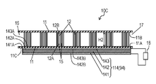
- FIG. 4C is a cross-sectional view of still another chemical substance concentrator 10C according to the embodiment.
- the chemical substance concentrator 10 ⁇ / b> C includes a heating unit 114 that is a desorption mechanism 94 that heats the adsorption unit 12 instead of the heating unit 14 of the chemical substance concentrator 10 illustrated in FIG. 3A.
- the heating unit 114 includes a lower electrode 141, nanofibers 142, and an upper electrode 143.
- the nanofiber 142 is provided between the lower electrode 141 and the upper electrode 143.
- the nanofiber 142 has conductivity.
- the nanofiber 142 is electrically connected to the lower electrode 141 and the upper electrode 143.
- the lower electrode 141 and the upper electrode 143 are connected to the external power source 18.
- the upper electrode 143 is provided on the outer surface 11 ⁇ / b> C of the cylindrical body 11.
- the nanofiber 142 generates heat due to the resistance of the nanofiber 142 when a current flows. Therefore, the nanofiber 142 can be used as the heating unit 14 of the chemical substance concentrator 10 shown in FIG. 3A.
- the heating unit 114 becomes high temperature with less power. Therefore, the adsorption part 12 can be efficiently heated with low power. Moreover, the heat capacity of the nanofiber 142 is small. Therefore, the cooling speed of the heating unit 114 is fast. Therefore, the heating unit 114 using the nanofibers 142 can increase the heating / cooling rate of the adsorption unit 12.
- the fibers 15 of the adsorption unit 12 and the nanofibers 142 of the heating unit 14 may be formed of the same material. Further, the fiber 15 and the nanofiber 142 may be formed of different materials.
- chemical substance concentrators 10A and 10B illustrated in FIGS. 4A and 4B may include the heating unit 114 illustrated in FIG. 4C instead of the heating unit 14.
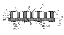
- FIG. 4D is a cross-sectional view of still another chemical substance concentrator 10D in the embodiment. 4D, the same reference numerals are assigned to the same parts as those in the chemical substance concentrator 10A shown in FIG. 4A.
- the chemical substance concentrator 10D includes a vibration unit 24 that is a desorption mechanism 94 instead of the heating unit 14 of the chemical substance concentrator 10A illustrated in FIG. 4A.
- the vibration unit 24 can desorb the molecule C10 of the chemical substance adsorbed on the adsorption unit 12 by vibrating the adsorption unit 12.
- the vibration unit 24 includes a lower electrode 241, a piezoelectric body 242 and an upper electrode 243.
- the lower electrode 241 has opposite surfaces 241A and 241B.
- the piezoelectric body 242 has opposite surfaces 242A and 242B.
- the upper electrode 243 has opposite surfaces 243A and 243B.
- the piezoelectric body 242 is provided between the lower electrode 241 and the upper electrode 243.
- a surface 241B of the lower electrode 241 is provided on the inner surface 11A of the cylinder 11.
- the surface 242B of the piezoelectric body 242 is provided on the surface 241A of the lower electrode 241.
- the surface 243B of the upper electrode 243 is provided on the surface 242A of the piezoelectric body 242.
- a plurality of insulating layers 20 are disposed on the surface 243 ⁇ / b> A of the upper electrode 243.
- the end portions 12B of the plurality of adsorption portions 12 are joined to the surface 243A of the upper electrode 243 via the insulating layer 20.
- an alternating voltage having a frequency of 1 MHz to 1 GHz between the lower electrode 241 and the upper electrode 243 the piezoelectric body 242 can be vibrated, and the molecule C10 of the chemical substance adsorbed on the adsorption portion 12 is desorbed by the vibration.
- the piezoelectric body 242 is made of, for example, a piezoelectric material such as Pb (Zr, Ti) O 3 (lead zirconate titanate) or AlN (aluminum nitride).
- FIG. 4E is a cross-sectional view of still another chemical substance concentrator 10E according to the embodiment.
- a chemical substance concentrator 10E shown in FIG. 4E includes a vibrating part 124 instead of the vibrating part 24 of the chemical substance concentrator 10D shown in FIG. 4D.
- the adsorption unit 12 is formed in one vibration unit 24.
- the vibration unit 124 has a plurality of regions 124A to 124C that are separated from each other.
- Each of the plurality of regions 124A to 124C of the vibration unit 124 includes a lower electrode 241, a piezoelectric body 242, and an upper electrode 243.
- the capacitance of each of the regions 124A to 124C of the vibration unit 124 can be reduced, so that the resonance frequency of the regions 124A to 124C of the vibration unit 124 can be increased, and the regions 124A to 124C of the vibration unit 124 can be increased.
- the regions 124A to 124C can be vibrated at different frequencies or at different timings, and selectivity can be given to desorption of molecules of the adsorbed chemical substance.
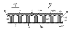
- FIG. 4F is a cross-sectional view of still another chemical substance concentrator 10F according to the embodiment.
- the chemical substance concentrator 10F includes a light irradiation unit 34 that functions as a desorption mechanism 94 instead of the heating unit 14 of the chemical substance concentrator 10 illustrated in FIG. 3A.
- the light irradiation unit 34 is provided on the outer surface 11 ⁇ / b> D of the cylindrical body 11. By irradiating the adsorption unit 12 with light from the light irradiation unit 34, the molecule C10 of the chemical substance adsorbed on the adsorption unit 12 can be desorbed.
- the cylinder 11 is preferably made of a material having a high light transmittance, such as glass.
- a halogen lamp, a laser, a near infrared lamp, an infrared lamp, or the like can be used.
- the heating units 14 and 114, the vibrating units 24 and 124, and the light irradiation unit 34 function as a desorption mechanism 94 that desorbs the molecule C10 of the chemical substance adsorbed on the adsorption unit 12.
- the detachment mechanism 94 may not necessarily be provided depending on the intended use of the chemical substance concentrators 10, 10A to 10F.
- an electrode may be connected to the fiber 15 of the adsorption unit 12 to pass an electric current.
- suction part 12 itself functions as a heating part.
- suction part 12 is not restricted to a cylindrical shape.
- the adsorption part 12 may have an elliptical column shape or a polygonal column shape.
- suction part 12 may have cone shape, a pyramid shape, or an elliptical cone shape.
- FIG. 4G is a top perspective view of still another chemical substance concentrator 10G in the embodiment.
- the adsorbing portions 12 are arranged in a row at intervals in the flow direction D10 from the inlet 16 toward the outlet 17 with the centers 12C of the plural adsorbing portions 12 overlapping. ing.
- the pressure loss of the fluid can be further reduced, the sample can be easily passed through the flow path 13 even with a small pump having a small transport capacity.
- the adsorption unit is filled with carbon nanofibers as an adsorbent inside the cylinder.
- the density of the adsorbent filled in the adsorbing part is high, the pressure loss of the adsorbing part becomes high. Therefore, the sample is difficult to pass through the adsorption part.
- FIG. 4H is a cross-sectional view of still another chemical substance concentrator 10H in the embodiment.
- the same parts as those in the chemical substance concentrator 10G shown in FIG. 4G are denoted by the same reference numerals.
- the plurality of adsorbing portions 12 are arranged in a row without any interval in the flow direction D10.
- the number of the adsorbing portions 12 provided along the flow direction D10 is one, and the distance D15 between adjacent fibers 15 of the fibers 15 arranged along the flow direction D10 in one adsorbing portion 12 is the adsorbing portion 112.
- a distance B1 see FIG.
- the adsorption unit 12 is not limited to an aggregate of a plurality of fibers 15.
- the adsorption part 12 may be formed of a material having a large number of fine pores such as a porous body.
- the sample containing chemical substance molecules is inserted into the chemical substance concentrator 10. Those molecules are adsorbed by the adsorption part 12 in the flow path.
- the height H1 of the flow path 13 is 30 ⁇ m, and the width W in the direction perpendicular to the height H1 and the flow direction D10 is 1 mm.
- the chemical concentrator 10 has a pressure loss of about 3.2 kPa and a Reynolds number of 4.9.
- the chemical substance concentrator 10 has a pressure loss of about 16 kPa and the Reynolds number is 24.7.
- the chemical concentrator 10 has a pressure loss of about 31.9 kPa and a Reynolds number of 49.3.
- a sample can be inserted into the chemical substance concentrator 10 using a small pump having a maximum static pressure of 80 kPa.
- the inserted sample A10 flows so as to circulate around the adsorbing portion 12 as a laminar flow, and flows along the flow path 13.
- the adsorbing portion 12 since the adsorbing portion 12 has a micro-size to sub-micro size uneven structure resulting from the fibers 15, vortex flows are generated in the vicinity of the unevenness.
- a heavy substance such as VOC contained in the sample hits the fiber 15 by centrifugal force, so that it can be effectively adsorbed by a normal cylindrical adsorbing portion.
- the Reynolds number is preferably less than 3000.
- the flow of the sample A10 becomes a laminar flow behind the adsorption unit 12.
- the Reynolds number is preferably less than 150.
- FIG. 5 is a side sectional view schematically showing still another chemical substance concentrator 30 in the embodiment.
- the same parts as those in the chemical substance concentrator 10 shown in FIGS. 1 to 3C are denoted by the same reference numerals.
- the chemical substance concentrator 30 is different from the chemical substance concentrator 10 in that it has a space above the adsorption unit 12. Other configurations are the same as those of the chemical substance concentrator 10.
- the chemical substance concentrator 30 has a cylindrical body 11 and a plurality of adsorption portions 12 provided on the inner surface 11A of the cylindrical body 11.
- the end portion 12B of the suction portion 12 is provided on the inner surface 11A, and the end portion 12A faces the inner surface 11B with a gap.
- a space through which the sample flows is formed above the adsorption unit 12, that is, between the end 12A of the adsorption unit 12 and the inner surface 11B.
- the height H3 that is the distance between the inner surfaces 11A and 11B of the flow path 13 is 40 ⁇ m
- the height H2 of the suction portion 12 is 30 ⁇ m.
- the suction part 12 is not in contact with the inner surface 11B. That is, the chemical substance concentrator 30 has a two-layer structure of a region 31 where the adsorption part 12 is formed and a region 32 where the adsorption part 12 is not formed.
- the pressure loss of the chemical substance concentrator 30 can be calculated in a state where the flow path in which the adsorption part 12 is formed and the flow path in which the adsorption part 12 is not formed are connected in parallel.
- the pressure loss is larger in the region 31 where the suction part 12 is formed than in the region 32 where the suction part 12 is not formed.
- the pressure loss in the region 31 is preferably the same as the pressure loss in the region 32 or a difference of about one digit.
- FIG. 6 is a side sectional view schematically showing still another chemical substance concentrator 30A in the embodiment.
- the adsorption unit 12 is inclined so as to extend toward the inlet 16 of the flow path 13.
- the end 15B of the fiber 15 is disposed on the inner surface 11A.
- the end 15 ⁇ / b> A of the fiber 15 is located closer to the inlet 16 of the flow path 13 than the end 15 ⁇ / b> B of the fiber 15. That is, the fiber 15 extends from the inner surface 11A at an acute angle with respect to the sample flow direction D10. That is, the end portions 12B of the plurality of adsorption portions 12 are located downstream of the end portion 12A in the sample flow direction D10.
- the molecules of the chemical substance are adsorbed not only on the end portion 12 ⁇ / b> A that is the upper surface of the adsorption portion 12 but also on the fibers 15 inside the adsorption portion 12.
- the fibers 15 inclined toward the inlet 16 are formed using crystalline fibers.
- crystalline fibers For example, when hexagonal ZnO is used, a crystal layer serving as a nucleus of the fiber 15 is formed.
- the crystal layer is formed using sputtering such as PVD (Physical Vapor Deposition).
- Particles deposited by sputtering fly with a wide solid angle.
- the c-axis direction of the obtained columnar crystal grows with dispersion from the vertical axis with respect to the substrate surface. Dispersion is strongly dependent on the flight angle of the particles.
- the target is offset and the portion directly above the target erosion part is masked with a shielding plate.
- a sputtering device flies particles so that a vertical component may not fly. Therefore, a columnar crystal layer having a c-axis inclined in one direction with respect to the substrate surface can be obtained.
- fibers 15 inclined with respect to the substrate surface can be obtained.
- the fiber 15 having an angle with respect to the flow direction D10 can be formed by setting the plane of the substrate to the inner surface 11A of the cylinder 11. The angle is, for example, 45 degrees to 80 degrees.
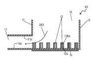
- FIG. 7 is a side sectional view schematically showing still another chemical substance concentrator 40 in the embodiment.
- the same parts as those in the chemical substance concentrator 10 shown in FIGS. 1 to 3C are denoted by the same reference numerals.
- the inlet 16 of the flow path 13 may be provided above the adsorption unit 12. That is, the fibers 15 of the adsorption part 12 extend vertically from the surface 14 ⁇ / b> A toward the inflow port 16. Accordingly, the flow direction D40 in which the sample flows has a component from the end 12A to the end 12B of the adsorption unit 12 and is inclined with respect to the adsorption unit 12.
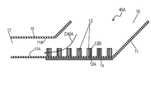
- FIG. 8 is a side sectional view schematically showing still another chemical substance concentrator 40A in the embodiment.
- the flow path 13 of the inlet 16 may be inclined with respect to the adsorption unit 12. That is, the inflow port 16 is provided above the side near the inflow port 16 of the inner surface 11 ⁇ / b> A provided with the adsorption portion 12. In this way, the suction portion 12 may be inclined relative to the flow path 13.
- the flow direction D40A in which the sample flows has a component from the end 12A to the end 12B of the adsorption unit 12 and is inclined with respect to the adsorption unit 12.
- the chemical substance concentrators 40 and 40A can efficiently adsorb chemical molecules.
- the chemical substance concentrator 10 (10A to 10H, 30, 30A, 40, 40A) includes the cylindrical body 11 and the plurality of adsorption portions 12 provided inside the cylindrical body 11.
- the cylindrical body 11 forms a flow path 13 in which a sample A10 containing a chemical substance flows in the flow direction D10.
- the plurality of adsorption units 12 adsorb chemical substances and desorb the adsorbed chemical substances.
- the adsorption part 12 is an aggregate of a plurality of fibers 15 made of a metal oxide.
- the plurality of adsorbing portions 12 are arranged with an interval B1 therebetween.
- the interval B ⁇ b> 1 between the adsorbing portions 12 adjacent to each other among the plurality of adsorbing portions 12 may be larger than the interval D ⁇ b> 1 between the plurality of fibers 15 in the adsorbing portion 12.
- the cylindrical body 11 may have an inner surface 11A on which a plurality of suction portions 12 are provided, and an inner surface 11B that faces the inner surface 11A of the cylindrical body 11 and is separated from the plurality of suction portions 12. .
- the end 12A of the adsorption unit 12 may be located downstream in the flow direction D10 from the end 12B.
- the plurality of fibers 15 may be made of ZnO.
- the desorption mechanism 94 desorbs the chemical substances adsorbed by the plurality of adsorption units 12 from the plurality of adsorption units 12.
- the desorption mechanism 94 may be a heating device 14 that heats the plurality of adsorption units 12.
- the desorption mechanism 94 may be a vibration unit 24 that vibrates the plurality of adsorption units 12.
- the desorption mechanism 94 may be the light irradiation unit 34 that irradiates light to the plurality of adsorption units 12.
- the plurality of suction units 12 may be arranged alternately.
- the plurality of suction units 12 may be arranged in a row.
- the plurality of adsorbing portions 12 may be arranged in a line in the cross section of the cylindrical body 11 other than the above cross section without leaving an interval.
- the plurality of adsorbing units 12 may desorb the adsorbed chemical substance into the sample A10.
- the chemical substance concentrators 10, 10A to 10H, 30, 30A, 40, and 40A may be provided, for example, in piping provided in the detection system.
- the cylinder 11 is a pipe of the detection system.
Landscapes
- Chemical & Material Sciences (AREA)
- Analytical Chemistry (AREA)
- Chemical Kinetics & Catalysis (AREA)
- Engineering & Computer Science (AREA)
- Health & Medical Sciences (AREA)
- Life Sciences & Earth Sciences (AREA)
- General Health & Medical Sciences (AREA)
- Pathology (AREA)
- Immunology (AREA)
- General Physics & Mathematics (AREA)
- Physics & Mathematics (AREA)
- Biochemistry (AREA)
- Organic Chemistry (AREA)
- General Chemical & Material Sciences (AREA)
- Oil, Petroleum & Natural Gas (AREA)
- Molecular Biology (AREA)
- Biomedical Technology (AREA)
- Inorganic Chemistry (AREA)
- Materials Engineering (AREA)
- Nanotechnology (AREA)
- Crystallography & Structural Chemistry (AREA)
- Electrochemistry (AREA)
- Sampling And Sample Adjustment (AREA)
- Solid-Sorbent Or Filter-Aiding Compositions (AREA)
- Separation Of Gases By Adsorption (AREA)
- Treating Waste Gases (AREA)
Abstract
Description
11 筒体
11A 内面(第一の内面)
11B 内面(第二の内面)
12 吸着部
12A 端部(第一の端部)
12B 端部(第二の端部)
13 流路
14 加熱部
15 繊維
16 流入口
17 排出口
18 電源
94 脱離機構
Claims (13)
- 化学物質を含む試料が流れ方向に流れる流路を形成する筒体と、
前記筒体の内部に設けられて、前記化学物質を吸着してかつ前記吸着した化学物質を脱離させる複数の吸着部と、
を備え、
前記複数の吸着部のそれぞれの吸着部は、金属酸化物からなる複数の繊維の集合体であり、
前記流れ方向に対して垂直な前記筒体の断面において、前記複数の吸着部は互いに間隔を空けて配置されている、化学物質濃縮器。 - 前記筒体の前記断面において、前記複数の吸着部のうちの互いに隣り合う吸着部の間の間隔は、前記複数の吸着部の前記それぞれの吸着部における前記複数の繊維の間の間隔よりも大きい、請求項1に記載の化学物質濃縮器。
- 前記筒体は、前記複数の吸着部が設けられている第一の内面と、前記筒体の前記第一の内面と対向してかつ前記複数の吸着部から離間している第二の内面とを有する、請求項2に記載の化学物質濃縮器。
- 前記筒体は、第一の内面と前記第一の内面に対向する第二の内面とを有し、
前記複数の吸着部の前記それぞれの吸着部は、前記第一の内面に設けられた第一の端部と、前記第一の端部の反対側にありかつ前記第二の内面に対向する第二の端部とを有し、
前記複数の吸着部の前記それぞれの吸着部の第一の端部は、前記第二の端部よりも、前記流れ方向において下流に位置している、請求項2に記載の化学物質濃縮器。 - 前記複数の繊維はZnOよりなる、請求項2に記載の化学物質濃縮器。
- 前記複数の吸着部に吸着された前記化学物質を前記複数の吸着部から脱離させる脱離機構をさらに備えた、請求項2に記載の化学物質濃縮器。
- 前記脱離機構は前記複数の吸着部を加熱する加熱装置である、請求項6に記載の化学物質濃縮器。
- 前記脱離機構は前記複数の吸着部を振動させる振動部である、請求項6に記載の化学物質濃縮器。
- 前記脱離機構は前記複数の吸着部に光を照射する光照射部である、請求項6に記載の化学物質濃縮器。
- 前記複数の吸着部は互い違いに配置されている、請求項1から9のいずれか一項に記載の化学物質濃縮器。
- 前記複数の吸着部は一列に配置されている、請求項1から9のいずれか一項に記載の化学物質濃縮器。
- 前記複数の吸着部は、前記筒体の前記断面以外の断面において間隔を空けずに一列に配置されている、請求項1から9のいずれか一項に記載の化学物質濃縮器。
- 前記複数の吸着部は、前記吸着した化学物質を前記試料内に脱離させる、請求項1から12のいずれか一項に記載の化学物質濃縮器。
Priority Applications (3)
| Application Number | Priority Date | Filing Date | Title |
|---|---|---|---|
| US15/555,207 US20180052083A1 (en) | 2015-04-28 | 2016-04-26 | Chemical substance concentrator |
| EP16786143.4A EP3290900A4 (en) | 2015-04-28 | 2016-04-26 | Chemical substance condenser |
| JP2017515390A JP6834947B2 (ja) | 2015-04-28 | 2016-04-26 | 化学物質濃縮器 |
Applications Claiming Priority (2)
| Application Number | Priority Date | Filing Date | Title |
|---|---|---|---|
| JP2015-091689 | 2015-04-28 | ||
| JP2015091689 | 2015-04-28 |
Publications (1)
| Publication Number | Publication Date |
|---|---|
| WO2016174866A1 true WO2016174866A1 (ja) | 2016-11-03 |
Family
ID=57198370
Family Applications (1)
| Application Number | Title | Priority Date | Filing Date |
|---|---|---|---|
| PCT/JP2016/002192 Ceased WO2016174866A1 (ja) | 2015-04-28 | 2016-04-26 | 化学物質濃縮器 |
Country Status (4)
| Country | Link |
|---|---|
| US (1) | US20180052083A1 (ja) |
| EP (1) | EP3290900A4 (ja) |
| JP (1) | JP6834947B2 (ja) |
| WO (1) | WO2016174866A1 (ja) |
Cited By (6)
| Publication number | Priority date | Publication date | Assignee | Title |
|---|---|---|---|---|
| WO2018079174A1 (ja) * | 2016-10-31 | 2018-05-03 | パナソニック株式会社 | 化学物質濃縮器および化学物質検出装置 |
| CN109513311A (zh) * | 2019-01-16 | 2019-03-26 | 上海环境保护有限公司 | 一种实现高效节能的动态流化床分级吸附的废气处理方法 |
| US20200018720A1 (en) * | 2017-03-28 | 2020-01-16 | Fujifilm Corporation | Gas detection method, gas detection system, and gas desorption method |
| EP3655132A4 (en) * | 2017-07-18 | 2020-07-22 | Environmental Management Confederation Inc. | DESIGN OF INCLINED ADSORBENT FILTER SUPPORTS IN TANGENTIAL FLOW APPLICATIONS |
| JP2023070495A (ja) * | 2021-11-09 | 2023-05-19 | 株式会社豊田中央研究所 | 濃縮器 |
| JP7471657B2 (ja) | 2021-11-24 | 2024-04-22 | 国立大学法人鳥取大学 | 呼気捕獲装置 |
Families Citing this family (3)
| Publication number | Priority date | Publication date | Assignee | Title |
|---|---|---|---|---|
| US11352884B2 (en) * | 2019-06-17 | 2022-06-07 | Halliburton Energy Services, Inc. | Downhole hydrogen sulfide capture and measurement |
| EP3872487B1 (en) | 2020-02-25 | 2022-10-05 | Carrier Corporation | Volatile alkene sensing device and method of using |
| EP4082434A1 (en) * | 2021-04-28 | 2022-11-02 | Merck Patent GmbH | An air or breath sampling device capturing both aerosol and vapor fractions |
Citations (6)
| Publication number | Priority date | Publication date | Assignee | Title |
|---|---|---|---|---|
| JP2001527220A (ja) * | 1997-12-24 | 2001-12-25 | シーフィード | 一体型流体操作カートリッジ |
| JP2003002621A (ja) * | 2001-06-21 | 2003-01-08 | Mitsubishi Electric Corp | 六弗化硫黄ガス回収装置 |
| JP2007125458A (ja) * | 2005-11-01 | 2007-05-24 | Sharp Corp | 空気調和機の有害化学ガス除去方法、空気調和機、および有害化学ガス除去フィルタ |
| JP2007171207A (ja) * | 2005-12-23 | 2007-07-05 | Korea Inst Of Science & Technology | 超高感度の金属酸化物ガスセンサ及びその製造方法 |
| JP2010139497A (ja) * | 2008-12-12 | 2010-06-24 | Korea Electronics Telecommun | 酸化物半導体ナノ繊維を利用した超高感度ガスセンサー及びその製造方法 |
| JP2015040819A (ja) * | 2013-08-23 | 2015-03-02 | 株式会社Nttドコモ | ガスの測定装置及びガスの測定方法 |
Family Cites Families (7)
| Publication number | Priority date | Publication date | Assignee | Title |
|---|---|---|---|---|
| US8152991B2 (en) * | 2005-10-27 | 2012-04-10 | Nanomix, Inc. | Ammonia nanosensors, and environmental control system |
| US7910064B2 (en) * | 2003-06-03 | 2011-03-22 | Nanosys, Inc. | Nanowire-based sensor configurations |
| US20100227382A1 (en) * | 2005-05-25 | 2010-09-09 | President And Fellows Of Harvard College | Nanoscale sensors |
| JP2009023881A (ja) * | 2007-07-20 | 2009-02-05 | Panasonic Corp | カーボンナノチューブおよびカーボンナノチューブ構造体 |
| CN102714137B (zh) * | 2009-10-16 | 2015-09-30 | 康奈尔大学 | 包括纳米线结构的方法和装置 |
| US20120301360A1 (en) * | 2011-05-26 | 2012-11-29 | Lockheed Martin Corporation | Nanostructured aerogel-thermoelectric device, making and using the same |
| WO2013175503A2 (en) * | 2012-05-22 | 2013-11-28 | Nanosniff Technologies Pvt. Ltd. | Nanostructure based mems preconcentrator |
-
2016
- 2016-04-26 WO PCT/JP2016/002192 patent/WO2016174866A1/ja not_active Ceased
- 2016-04-26 EP EP16786143.4A patent/EP3290900A4/en not_active Withdrawn
- 2016-04-26 US US15/555,207 patent/US20180052083A1/en not_active Abandoned
- 2016-04-26 JP JP2017515390A patent/JP6834947B2/ja active Active
Patent Citations (6)
| Publication number | Priority date | Publication date | Assignee | Title |
|---|---|---|---|---|
| JP2001527220A (ja) * | 1997-12-24 | 2001-12-25 | シーフィード | 一体型流体操作カートリッジ |
| JP2003002621A (ja) * | 2001-06-21 | 2003-01-08 | Mitsubishi Electric Corp | 六弗化硫黄ガス回収装置 |
| JP2007125458A (ja) * | 2005-11-01 | 2007-05-24 | Sharp Corp | 空気調和機の有害化学ガス除去方法、空気調和機、および有害化学ガス除去フィルタ |
| JP2007171207A (ja) * | 2005-12-23 | 2007-07-05 | Korea Inst Of Science & Technology | 超高感度の金属酸化物ガスセンサ及びその製造方法 |
| JP2010139497A (ja) * | 2008-12-12 | 2010-06-24 | Korea Electronics Telecommun | 酸化物半導体ナノ繊維を利用した超高感度ガスセンサー及びその製造方法 |
| JP2015040819A (ja) * | 2013-08-23 | 2015-03-02 | 株式会社Nttドコモ | ガスの測定装置及びガスの測定方法 |
Non-Patent Citations (1)
| Title |
|---|
| See also references of EP3290900A4 * |
Cited By (9)
| Publication number | Priority date | Publication date | Assignee | Title |
|---|---|---|---|---|
| WO2018079174A1 (ja) * | 2016-10-31 | 2018-05-03 | パナソニック株式会社 | 化学物質濃縮器および化学物質検出装置 |
| US20200018720A1 (en) * | 2017-03-28 | 2020-01-16 | Fujifilm Corporation | Gas detection method, gas detection system, and gas desorption method |
| US10718735B2 (en) * | 2017-03-28 | 2020-07-21 | Fujifilm Corporation | Gas detection method, gas detection system, and gas desorption method |
| EP3655132A4 (en) * | 2017-07-18 | 2020-07-22 | Environmental Management Confederation Inc. | DESIGN OF INCLINED ADSORBENT FILTER SUPPORTS IN TANGENTIAL FLOW APPLICATIONS |
| US11524257B2 (en) | 2017-07-18 | 2022-12-13 | Environmental Management Confederation, Inc. | Angled adsorbent filter media design in tangential flow applications |
| CN109513311A (zh) * | 2019-01-16 | 2019-03-26 | 上海环境保护有限公司 | 一种实现高效节能的动态流化床分级吸附的废气处理方法 |
| JP2023070495A (ja) * | 2021-11-09 | 2023-05-19 | 株式会社豊田中央研究所 | 濃縮器 |
| JP7593300B2 (ja) | 2021-11-09 | 2024-12-03 | 株式会社豊田中央研究所 | 濃縮器 |
| JP7471657B2 (ja) | 2021-11-24 | 2024-04-22 | 国立大学法人鳥取大学 | 呼気捕獲装置 |
Also Published As
| Publication number | Publication date |
|---|---|
| EP3290900A1 (en) | 2018-03-07 |
| US20180052083A1 (en) | 2018-02-22 |
| JP6834947B2 (ja) | 2021-02-24 |
| EP3290900A4 (en) | 2018-04-18 |
| JPWO2016174866A1 (ja) | 2018-02-22 |
Similar Documents
| Publication | Publication Date | Title |
|---|---|---|
| JP6834947B2 (ja) | 化学物質濃縮器 | |
| US11946842B1 (en) | Thermophoretic particle concentrator | |
| US9403114B2 (en) | Air purification system and method using an ultrasonic wave | |
| CN107683407B (zh) | 化学物质检测装置 | |
| US7291271B2 (en) | Meso-frequency traveling wave electro-kinetic continuous adsorption system | |
| CN108136314B (zh) | 化学物质浓缩器以及化学物质检测器 | |
| CA2761080C (en) | Ceramic filter and ceramic vapor-permeable filter | |
| US7531027B2 (en) | Contaminant extraction systems, methods, and apparatuses | |
| CN103877834B (zh) | 除湿系统 | |
| CN109690280B (zh) | 化学物质浓缩器以及化学物质检测装置 | |
| US20100050866A1 (en) | Nanowire filter, method for manufacturing the same, method for removing material absorbed thereon, and filtering apparatus having the same | |
| RU2639908C2 (ru) | Устройство для сепарации кислорода для адсорбционной системы с реверсированием давления | |
| JPWO2016103561A1 (ja) | 化学物質濃縮器および化学物質検出装置 | |
| JP2019527365A (ja) | ガス採取用カテーテル | |
| JP6113593B2 (ja) | 空気清浄化装置および空気清浄化方法 | |
| US9352246B2 (en) | Evaporation device | |
| TW201424826A (zh) | 除濕系統 | |
| KR101539560B1 (ko) | 탄소나노튜브 폼, 이의 제조방법 및 이를 이용한 마이크로 전농축기 모듈 | |
| CN109420387A (zh) | 气体清净装置 | |
| JP2004000926A (ja) | エアフィルタ用濾材、エアフィルタユニット、及びその製造方法、並びにその包装体 | |
| US9272238B1 (en) | Plasma generation through ceramic substrate | |
| CN112237990A (zh) | 一种集尘极和除尘器 |
Legal Events
| Date | Code | Title | Description |
|---|---|---|---|
| 121 | Ep: the epo has been informed by wipo that ep was designated in this application |
Ref document number: 16786143 Country of ref document: EP Kind code of ref document: A1 |
|
| ENP | Entry into the national phase |
Ref document number: 2017515390 Country of ref document: JP Kind code of ref document: A |
|
| WWE | Wipo information: entry into national phase |
Ref document number: 15555207 Country of ref document: US |
|
| REEP | Request for entry into the european phase |
Ref document number: 2016786143 Country of ref document: EP |
|
| NENP | Non-entry into the national phase |
Ref country code: DE |