WO2016174940A1 - 引っ掻き摩耗試験装置および方法 - Google Patents
引っ掻き摩耗試験装置および方法 Download PDFInfo
- Publication number
- WO2016174940A1 WO2016174940A1 PCT/JP2016/057531 JP2016057531W WO2016174940A1 WO 2016174940 A1 WO2016174940 A1 WO 2016174940A1 JP 2016057531 W JP2016057531 W JP 2016057531W WO 2016174940 A1 WO2016174940 A1 WO 2016174940A1
- Authority
- WO
- WIPO (PCT)
- Prior art keywords
- rubber sample
- contact member
- rubber
- belt body
- scratch
- Prior art date
- Legal status (The legal status is an assumption and is not a legal conclusion. Google has not performed a legal analysis and makes no representation as to the accuracy of the status listed.)
- Ceased
Links
Images


Classifications
-
- G—PHYSICS
- G01—MEASURING; TESTING
- G01N—INVESTIGATING OR ANALYSING MATERIALS BY DETERMINING THEIR CHEMICAL OR PHYSICAL PROPERTIES
- G01N3/00—Investigating strength properties of solid materials by application of mechanical stress
- G01N3/56—Investigating resistance to wear or abrasion
-
- G—PHYSICS
- G01—MEASURING; TESTING
- G01N—INVESTIGATING OR ANALYSING MATERIALS BY DETERMINING THEIR CHEMICAL OR PHYSICAL PROPERTIES
- G01N3/00—Investigating strength properties of solid materials by application of mechanical stress
- G01N3/02—Details
-
- G—PHYSICS
- G01—MEASURING; TESTING
- G01N—INVESTIGATING OR ANALYSING MATERIALS BY DETERMINING THEIR CHEMICAL OR PHYSICAL PROPERTIES
- G01N2203/00—Investigating strength properties of solid materials by application of mechanical stress
- G01N2203/003—Generation of the force
- G01N2203/0032—Generation of the force using mechanical means
- G01N2203/0033—Weight
-
- G—PHYSICS
- G01—MEASURING; TESTING
- G01N—INVESTIGATING OR ANALYSING MATERIALS BY DETERMINING THEIR CHEMICAL OR PHYSICAL PROPERTIES
- G01N2203/00—Investigating strength properties of solid materials by application of mechanical stress
- G01N2203/003—Generation of the force
- G01N2203/005—Electromagnetic means
-
- G—PHYSICS
- G01—MEASURING; TESTING
- G01N—INVESTIGATING OR ANALYSING MATERIALS BY DETERMINING THEIR CHEMICAL OR PHYSICAL PROPERTIES
- G01N2203/00—Investigating strength properties of solid materials by application of mechanical stress
- G01N2203/02—Details not specific for a particular testing method
- G01N2203/022—Environment of the test
- G01N2203/0222—Temperature
- G01N2203/0226—High temperature; Heating means
-
- G—PHYSICS
- G01—MEASURING; TESTING
- G01N—INVESTIGATING OR ANALYSING MATERIALS BY DETERMINING THEIR CHEMICAL OR PHYSICAL PROPERTIES
- G01N2203/00—Investigating strength properties of solid materials by application of mechanical stress
- G01N2203/02—Details not specific for a particular testing method
- G01N2203/026—Specifications of the specimen
- G01N2203/0262—Shape of the specimen
- G01N2203/0278—Thin specimens
- G01N2203/0282—Two dimensional, e.g. tapes, webs, sheets, strips, disks or membranes
-
- G—PHYSICS
- G01—MEASURING; TESTING
- G01N—INVESTIGATING OR ANALYSING MATERIALS BY DETERMINING THEIR CHEMICAL OR PHYSICAL PROPERTIES
- G01N2203/00—Investigating strength properties of solid materials by application of mechanical stress
- G01N2203/02—Details not specific for a particular testing method
- G01N2203/06—Indicating or recording means; Sensing means
- G01N2203/0641—Indicating or recording means; Sensing means using optical, X-ray, ultraviolet, infrared or similar detectors
-
- G—PHYSICS
- G01—MEASURING; TESTING
- G01N—INVESTIGATING OR ANALYSING MATERIALS BY DETERMINING THEIR CHEMICAL OR PHYSICAL PROPERTIES
- G01N2203/00—Investigating strength properties of solid materials by application of mechanical stress
- G01N2203/02—Details not specific for a particular testing method
- G01N2203/06—Indicating or recording means; Sensing means
- G01N2203/067—Parameter measured for estimating the property
- G01N2203/0676—Force, weight, load, energy, speed or acceleration
-
- G—PHYSICS
- G01—MEASURING; TESTING
- G01N—INVESTIGATING OR ANALYSING MATERIALS BY DETERMINING THEIR CHEMICAL OR PHYSICAL PROPERTIES
- G01N2203/00—Investigating strength properties of solid materials by application of mechanical stress
- G01N2203/02—Details not specific for a particular testing method
- G01N2203/06—Indicating or recording means; Sensing means
- G01N2203/067—Parameter measured for estimating the property
- G01N2203/0682—Spatial dimension, e.g. length, area, angle
-
- G—PHYSICS
- G01—MEASURING; TESTING
- G01N—INVESTIGATING OR ANALYSING MATERIALS BY DETERMINING THEIR CHEMICAL OR PHYSICAL PROPERTIES
- G01N2203/00—Investigating strength properties of solid materials by application of mechanical stress
- G01N2203/02—Details not specific for a particular testing method
- G01N2203/06—Indicating or recording means; Sensing means
- G01N2203/067—Parameter measured for estimating the property
- G01N2203/0694—Temperature
Definitions
- the present invention relates to a scratch wear test apparatus and method, and more particularly to a scratch wear test apparatus and method capable of accurately predicting the scratch wear resistance of an upper cover rubber of a conveyor belt in actual use. .
- a DIN abrasion tester and a Williams abrasion tester are known as testers for evaluating the wear resistance of rubber.
- These wear testing machines are not testing machines for grasping scratch wear. Therefore, in order to accurately predict the scratch wear resistance of the upper cover rubber of the conveyor belt in actual use, a testing machine with a new specification has been required.
- An object of the present invention is to provide a scratch wear test apparatus and method capable of accurately predicting the scratch wear resistance of the upper cover rubber of a conveyor belt in actual use.
- a scratch wear test apparatus includes a pair of pulleys, an annular belt body stretched between the pair of pulleys, and a rubber sample fixed to the outer peripheral surface of the belt body.
- a contact member having a sharp tip that can contact the surface of the rubber sample; a pressing mechanism that presses the tip of the contact member against the surface of the rubber sample; and a weight member that changes a pressing load applied by the contact member.
- the contact member has a plurality of types of contact members having different tip specifications, and a contact member that presses the surface of the rubber sample from the plurality of types of contact members. Arbitrarily selected, the selected contact member is pressed against the surface of the rubber sample.
- an annular belt body having a rubber sample fixed on the outer peripheral surface is stretched between a pair of pulleys, and a contact member having a pointed tip by a pressing mechanism with respect to the surface of the rubber sample
- a wear test method for pressing the rubber sample wherein when testing, the running speed of the rubber sample is set to a desired speed, the pressing load by the contact member is set to a desired pressing load by a weight member, and the contact A desired contact member is selected from a plurality of types of contact members having different specifications of the tip that contacts the surface of the rubber sample provided as a member, and the selected contact member is pressed against the surface of the rubber sample.
- the travel speed of the rubber sample and the pressing load by the contact member can be set to desired settings.
- tip of a desired specification can be pressed on the surface of the said rubber sample.
- a rubber sample fixed to the outer periphery of the annular belt body is used, when testing the abrasion resistance of a rubber sample having the same specifications as the rubber used for the upper cover rubber of the conveyor belt, Evaluation can be performed under conditions similar to the actual usage environment. Therefore, it is possible to accurately predict the scratch wear resistance of the upper cover rubber of the conveyor belt in actual use. In addition, the influence of tension on the scratch resistance of the conveyor belt can be grasped.
- the rubber sample of an arbitrary period It becomes possible to quickly grasp the amount of scratch wear. Moreover, the amount of scratch wear can be grasped without removing the rubber sample from the pair of pulleys.
- a support portion for supporting the inner peripheral surface of the belt body is provided between the pair of pulleys, and the contact member is arranged at a position where the support portion supports the belt body and a position where the belt body is not supported.
- the scratch wear test apparatus of the present invention can also include a load sensor that sequentially detects the pressing load acting on the contact member and the running direction load of the rubber sample. This makes it possible to grasp the dynamic friction coefficient of the rubber sample.
- a temperature sensor for detecting the surface temperature of the rubber sample can be provided. Thereby, the surface temperature change of the rubber sample under evaluation can be measured, and the energy generated when the rubber sample is worn can be grasped.
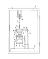
- FIG. 1 is an explanatory view illustrating the scratch wear test apparatus of the present invention in a front view.
- FIG. 2 is a cross-sectional view taken along the line AA in FIG.
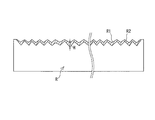
- FIG. 3 is an explanatory view schematically illustrating the cross-sectional shape in the width direction of the surface of the rubber sample detected by the shape sensor.
- FIG. 4 is an explanatory view showing another embodiment of the scratch wear test apparatus in a front view.
- FIG. 5 is an explanatory view showing still another embodiment of the scratch wear test apparatus in a front view.
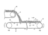
- FIG. 6 is an explanatory view illustrating a conveyor belt line in a simplified manner.
- 7 is a cross-sectional view taken along the line BB of FIG.
- the conveyed product S conveyed by another conveyor belt 18 is input to the conveyor belt 12 and conveyed to the conveyance destination by this conveyor belt 12. .
- the conveyed product S may be put into the conveyor belt 12 through a hopper or the like.
- the conveyor belt 12 is stretched between pulleys 16a and 16b and is stretched with a predetermined tension.
- the conveyor belt 12 is composed of a core body layer 13 composed of a core body such as a canvas or a steel cord, and an upper cover rubber 14 and a lower cover rubber 15 sandwiching the core body layer 13.
- the core body layer 13 is a member that bears a tension for tensioning the conveyor belt 12.
- the lower cover rubber 15 is supported by the support roller 17 on the carrier side of the conveyor belt 12, and the upper cover rubber 14 is supported by the support roller 17 on the return side.
- Three support rollers 17 are arranged in the belt width direction on the carrier side of the conveyor belt 12, and the conveyor belt 12 is supported in a concave shape at a predetermined trough angle a by these support rollers 17.
- the driving pulley 16a is rotationally driven, the conveyor belt 12 operates at a predetermined traveling speed V in one direction.
- the conveyed product S is put on the upper cover rubber 14, loaded on the upper cover rubber 14, and conveyed.
- a scratch wear test apparatus 1 (hereinafter referred to as “test apparatus 1”) of the present invention illustrated in FIGS. 1 to 2 includes a pair of pulleys 7a and 7b, a contact member 4, and an arm to which the contact member 4 is detachably attached. It comprises a part 3, a weight member 5 that is detachably attached to the arm part 3, and a control part 6a. Furthermore, in this embodiment, the casing in which the shape sensor 9a, the calculation unit 11, the support unit 17a, the load sensor 9b, the temperature sensor 9c, the heating plate 10a, and the above-described components excluding the control unit 6a and the calculation unit 11 are provided. 10.
- the heating plate 10a has a wider specification than the rubber sample R, and can heat and maintain the rubber sample R at a desired temperature. If the rubber sample R can be set to a desired temperature by maintaining the internal space at a desired temperature using a so-called thermostat as the casing 10, the heating plate 10a can be omitted. In addition to the temperature, the casing 10 that can maintain the internal space at a desired humidity can be employed.
- the pulleys 7a and 7b are rotatably supported by a support base 8 provided upright on the base 2a. At least one of the pulleys 7a and 7b moves horizontally, and the distance between the pulleys 7a and 7b is variable.
- One pulley 7 a is rotationally driven by the drive motor 6.
- the other pulley 7b rotates freely.
- the rotation speed of the pulley 7a is variable and can be set to a desired rotation speed. This rotational speed is controlled by the controller 6a.
- the pulley 7a and the drive motor 6 can be configured to transmit driving force by a transmission mechanism such as a gear or a belt.
- An annular belt B is stretched between the pulley 7a and the pulley 7b.
- a rubber sample R is fixed to the outer peripheral surface of the belt body B.
- a recess is provided on the outer peripheral side of the belt body B, and the rubber sample R is fitted into the recess.
- the outer peripheral surface of the belt body B and the rubber sample R can be integrated by friction generated between each other, or can be integrated by an adhesive applied between each other.
- the rubber sample R can be integrated by being vulcanized and bonded to the outer peripheral surface of the belt body B.
- a flat plate-like support portion 17a that supports the inner peripheral surface of the belt body B is provided between the pulley 7a and the pulley 7b.
- the support portion 17a is optionally provided as necessary.
- the arm portion 3 is pivotally supported by a rotary shaft 3b so as to be rotatable in the vertical direction with respect to a post 2b erected on the base 2a.
- a pin 5 c is provided at one longitudinal end of the arm portion 3.
- the pin 5c and the weight member 5 are connected via a pulley 5b by a wire 5a.
- the arm portion 3, the wire 5a, and the pulley 5b constitute a pressing mechanism that presses the contact member 4 against the surface of the rubber sample R as described later.
- the contact member 4 is attached to the arm portion 3 so as to be in contact with the surface of the rubber sample R. More specifically, the contact member 4 is detachably attached to the holding portion 3a fixed to the other end portion of the arm portion 3 in the longitudinal direction.
- the contact member 4 includes a plurality of types having different specifications (shape, hardness, material, etc.) of the tip that contacts the surface of the rubber sample R. That is, a contact member 4 (4a, 4b, 4c) having a contact surface with a specification similar to the surface of the conveyed product S conveyed by the conveyor belt 12 having the upper cover rubber 14 of the same specification as the rubber sample R is provided. .
- a plurality of types of contact members 4 having contact surfaces similar to these are provided.
- An arbitrary contact member 4 is selected from a plurality of types of contact members 4 (4a, 4b, 4c) and attached to the holding portion 3a.
- the weight member 5 is detachably attached to the end of the wire 5a, and the number, type, and the like of the weight member 5 to be attached can be appropriately changed. Due to the load of the weight member 5, the pin 5c connected to the wire 5a is lifted upward, and the arm portion 3 is pivoted up and down around the rotation shaft 3b located in the middle of the longitudinal direction of the arm portion 3. To do. Along with this, the contact member 4 presses the surface of the rubber sample R.
- the arm part 3, the wire 5a, and the pulley 5b comprise the press mechanism, if the contact member 4 can be pressed on the surface of the rubber sample R, another press mechanism can be employ
- the weight member 5 only needs to change the pressing load applied to the rubber sample R by the contact member 4. That is, the pressing force of the contact member 4 against the surface of the rubber sample R can be changed depending on the weight of the weight member 5.
- the shape sensor 9a is attached to the casing 10, for example, and detects the cross-sectional shape of the surface of the rubber sample R. Data detected by the shape sensor 9 a is input to the calculation unit 11.
- Various sensors can be used as the shape sensor 9a. For example, a sensor that detects the distance by receiving laser light irradiated on the surface of the rubber sample R is used.
- the load sensor 9 b is attached to the lower surface of the other end portion in the longitudinal direction of the arm portion 3.
- the load sensor 9b sequentially detects the pressing load acting on the contact member 4 and the traveling direction load of the annular belt body B stretched between the pulleys 7a and 7b. That is, the vertical load and the horizontal load acting on the contact member 4 pressing the belt body B (rubber sample R) are sequentially detected by the load sensor 9b.
- the temperature sensor 9c sequentially detects the surface temperature of the rubber sample R. Data detected by the load sensor 9b and the temperature sensor 9c is input to the control unit 6a.
- the rubber sample R to be evaluated is fixed to the outer peripheral surface of the annular belt body B stretched between the pulleys 7a and 7b, and the drive motor 6 is driven to rotate. At this time, the belt body B (rubber sample R) is stretched with a desired tension by adjusting the distance between the pulleys 7a and 7b. Further, the traveling speed of the belt body B is set to a desired speed, and the pressing load on the surface of the rubber sample R of the contact member 4 by the pressing mechanism is set to a desired pressing load by the weight member 5.
- the contact member 4 selects a desired contact member from a plurality of types of contact members 4 (4a, 4b, 4c) and attaches it to the holding portion 3a. Thereby, while pressing the desired contact member 4 on the surface of the rubber sample R, the cross-sectional shape of the surface of the rubber sample R is detected by the shape sensor 9a. In this embodiment, the contact member 4 presses the surface of the rubber sample R at a position directly above the support portion 17a. Since the rubber sample R travels while being continuously pressed by the contact member 4 with a predetermined pressing load, the surface is scratched by the contact member 4 having a sharp tip and is worn in a streak shape.
- the rubber sample R to be evaluated can be evaluated under conditions similar to the actual usage environment of the conveyor belt 12. That is, the traveling speed of the annular belt body B (rubber sample R) stretched between the pulleys 7a and 7b is equal to the horizontal speed of the conveyed product S when it is put into the conveyor belt 12, and the horizontal speed of the conveyor belt 12. The difference from the traveling speed in the direction, that is, the relative speed in the horizontal direction between the conveyor belt 12 and the loaded material S is set to the same condition.
- the pressing load by the contact member 4 is set to a condition equivalent to the pressing load that the conveyor belt 12 receives from the transported object S according to the input weight of the transported object S per unit time, the input height, and the like.
- the annular belt body B since the annular belt body B is used, the conditions can be made very similar to the actual usage environment of the conveyor belt 12. Therefore, it is possible to accurately predict the scratch wear resistance of the upper cover rubber 14 (rubber sample R) of the conveyor belt 12 in actual use. The influence of the tension on the scratch resistance of the rubber sample R can also be grasped.
- the calculation unit 11 calculates the scratch wear amount of the rubber sample R based on the detection data by the shape sensor 9a. Specifically, as shown in FIG. 3, the vertical displacement H between the surface R1 at the previous detection and the surface R2 at the current detection is obtained, and the numerical value is integrated in the width direction section of the rubber sample R. The amount of scratch wear (area of the hatched portion) of the rubber sample R in the detection cross section can be calculated. By performing this calculation for the entire circumference in the longitudinal direction of the rubber sample R, the amount of scratch wear in the entire rubber sample R can be calculated. Alternatively, the scratch wear amount per unit length of the rubber sample R is calculated. Thus, it becomes possible to quickly grasp the amount of scratch wear of the rubber sample R at an arbitrary position (range) in an arbitrary period.
- the weight of the rubber sample R is measured before and after the rubber sample R is scratched by the contact member 4, and the wear amount is calculated based on the difference in the measured weight. It was. At this time, it was necessary to remove the rubber sample R from the pair of pulleys 7a and 7b. In particular, if the pulleys 7a and 7b are pivotally supported by a double-supported structure, a large number of man-hours are required for the work of removing the rubber sample R. However, according to the test apparatus 1, it is possible to grasp the amount of scratch wear without removing the rubber sample R from the pair of pulleys 7a. Therefore, the working efficiency is remarkably improved.
- each of the pulleys 7a and 7b is pivotally supported by a cantilever structure, but can be configured to be pivotally supported by a both-end support structure. If each pulley 7a, 7b has a double-sided structure, the belt body B (rubber sample R) can run more stably. In addition, since most of the pulleys of an actual conveyor device have a double-sided structure, the conditions can be made more similar to the actual usage environment of the conveyor belt. If each pulley 7a, 7b has a double-sided structure, the man-hour required to remove the rubber sample R from the pair of pulleys 7a, 7b increases as described above. Can be reduced.
- the belt body B and the rubber sample R are made non-adhering so that they can be separated from each other, there is an advantage that only the used rubber sample R needs to be replaced and the belt body B can be used repeatedly. Further, when the amount of scratching of the rubber sample R is grasped, if the position in the longitudinal direction of the rubber sample R is divided in the belt width direction, only the rubber sample R can be easily removed from the pair of pulleys 7a and 7b. Therefore, the scratch wear amount of the rubber sample R can be grasped based on the measured weight of the rubber sample R without requiring a great number of man-hours without using the shape sensor 9a.
- the contact member 4 is not supported by the position where the support portion 17a supports the belt body B and the belt body B. It can be pressed against the surface of the rubber sample R depending on the position. Thereby, it is possible to grasp the difference in scratch wear resistance (wear amount, wear state, etc.) of the rubber sample R at the two positions. Therefore, the scratch wear resistance of the upper cover rubber 14 (rubber sample R) of the conveyor belt 12 in actual use can be predicted with higher accuracy.
- the pressing load (that is, the vertical load) acting on the contact member 4 and the running direction load (that is, the horizontal load) of the rubber sample R are sequentially detected. Therefore, it is possible to grasp the dynamic friction coefficient of the rubber sample R based on the detection data.
- the external environment temperature of the rubber sample R can be set to a desired temperature. Therefore, it becomes possible to perform evaluation under conditions that are more similar to the actual usage environment of the conveyor belt 12. Further, by performing the evaluation while varying the external environment temperature and the temperature of the rubber sample R, the temperature dependence of the scratch wear resistance of the rubber sample R can be grasped.
- the temperature sensor 9c since the temperature sensor 9c is provided, it is possible to measure the surface temperature change of the rubber sample R under evaluation. Since heat energy is generated when the rubber sample R is worn, it is possible to grasp the energy when worn by the temperature measurement result by the temperature sensor 9c. Since the magnitude of this energy varies depending on the type of rubber, the temperature measurement result is useful, for example, in selecting a rubber type that can reduce this energy.
- the support portion 17 a that supports the inner peripheral surface of the annular belt body B between the pulley 7 a and the pulley 7 b can move in the traveling direction of the belt body B. It is a mechanism that can be fixed at any position moved.
- Other basic configurations are the same as in the previous embodiment.
- As the support portion 17a not only a flat plate shape but also a support roller can be used as in this embodiment. Since the support portion 17a can move, the span (the support length of the belt body B pressed by the contact member 4) can be changed. Accordingly, when the contact member 4 is pressed against the surface of the rubber sample R at the position where the support portion 17a does not support the belt body B, the influence of the span on the scratch wear resistance can also be grasped.
- the mechanism which makes the support part 17a movable is not specifically limited.
- a mechanism that can move steplessly or a mechanism that can move stepwise may be used.
- As a mechanism for making the support portion 17a movable for example, there is a method of setting a rail on the base 2a so that the support portion 17a can slide on the rail.
- the pressing mechanism of this embodiment has a plurality of weight members 5 placed on the contact member 4. Specifically, the base 3d to which the holding portion 3a attached to the upper end of the contact member 4 is attached, the support 3e standing upward from the base 3d, and a plurality of weight members 5 through which the support 3e passes. A pressing mechanism is configured. These weight members 5 are placed on the base 3d in a stacked state. The base 3d is held by another member so as not to be displaced in the horizontal direction.
- substantially the total weight of the base 3d, the column 3e and the weight member 5 acts on the surface of the rubber sample R via the contact member 4. Therefore, the pressing force on the surface of the rubber sample R can be changed by varying the number of weight members 5 and the weight of each weight member 5.
- the pressing mechanism since the rubber sample R is substantially only subjected to a vertical downward load and hardly fluctuates up and down, the vertical vibration of the rubber sample R accompanying the running of the rubber sample R is effectively suppressed. can do. From this point of view, high-precision measurement with less noise can be performed, which is advantageous for predicting the scratch wear resistance and dynamic friction coefficient of the rubber sample R with higher accuracy. Furthermore, there is an advantage that the pressing mechanism can be simplified.
Landscapes
- Physics & Mathematics (AREA)
- Health & Medical Sciences (AREA)
- Life Sciences & Earth Sciences (AREA)
- Chemical & Material Sciences (AREA)
- Analytical Chemistry (AREA)
- Biochemistry (AREA)
- General Health & Medical Sciences (AREA)
- General Physics & Mathematics (AREA)
- Immunology (AREA)
- Pathology (AREA)
- Investigating Strength Of Materials By Application Of Mechanical Stress (AREA)
Abstract
Description
2a ベース
2b ポスト
2c 可動台
3 アーム部
3a 保持部
3b 回転軸
3c 軸孔
3d 基台
3e 支柱
4(4a、4b、4c) 接触部材
5 錘部材
5a ワイヤー
5b 滑車
5c 接続部材
6 駆動モータ
6a 制御部
7a、7b プーリ
8 支持台
9a 形状センサ
9b 荷重センサ
9c 温度センサ
10 ケーシング(温調機構)
10a 加熱板(温調機構)
11 演算部
12 コンベヤベルト
13 心体層
14 上カバーゴム
15 下カバーゴム
16a、16b プーリ
17 支持ローラ
17a 支持部
18 別のコンベヤベルト
B ベルト体
R ゴムサンプル
R1 前回検知時のゴムサンプルの表面
R2 今回検知時のゴムサンプルの表面
S 搬送物
Claims (9)
- 一対のプーリと、この一対のプーリの間に張設される環状のベルト体と、このベルト体の外周面に固定されるゴムサンプルと、このゴムサンプルの表面に接触可能な先端が尖った接触部材と、この接触部材の先端を前記ゴムサンプルの表面に押圧する押圧機構と、前記接触部材による押圧荷重を変化させる錘部材とを備え、前記ゴムサンプルの走行速度を可変にするとともに、前記接触部材として、先端の仕様が異なる複数種類の接触部材を有し、この複数種類の接触部材から前記ゴムサンプルの表面を押圧する接触部材が任意に選択され、選択された接触部材を前記ゴムサンプルの表面に押圧する構成にしたことを特徴とする引っ掻き摩耗試験装置。
- 前記ゴムサンプルの表面の断面形状を検知する形状センサと、この形状センサによる検知データに基づいて前記ゴムサンプルの引っ掻き摩耗量を算出する演算部とを備えた請求項1に記載の引っ掻き摩耗試験装置。
- 前記一対のプーリ間に前記ベルト体の内周面を支持する支持部を設け、前記接触部材を、前記支持部が前記ベルト体を支持する位置と、前記ベルト体を支持しない位置とで前記ゴムサンプルの表面に押圧できる構成にした請求項1または2に記載の引っ掻き摩耗試験装置。
- 前記接触部材に作用する前記押圧荷重および前記ゴムサンプルの走行方向荷重を逐次検知する荷重センサを備える請求項1~3のいずれかに記載の引っ掻き摩耗試験装置。
- 前記ゴムサンプルの外部環境温度を可変にする温調機構を備える請求項1~4のいずれかに記載の引っ掻き摩耗試験装置。
- 前記ゴムサンプルの表面温度を検知する温度センサを備える請求項1~5のいずれかに記載の引っ掻き摩耗試験装置。
- 外周面にゴムサンプルを固定した環状のベルト体を一対のプーリの間に張設し、このゴムサンプルの表面に対して、押圧機構によって先端が尖った接触部材を押圧する摩耗試験方法であって、試験する際には、前記ゴムサンプルの走行速度を所望の速度に設定し、前記接触部材による押圧荷重を錘部材によって所望の押圧荷重に設定し、前記接触部材として備えている前記ゴムサンプルの表面と接触する先端の仕様が異なる複数種類の接触部材から所望の接触部材を選択し、選択した接触部材を前記ゴムサンプルの表面に押圧することを特徴とする引っ掻き摩耗試験方法。
- 前記ゴムサンプルの表面の断面形状を形状センサにより検知し、この形状センサによる検知データに基づいて前記ゴムサンプルの引っ掻き摩耗量を演算部により算出する請求項7に記載の引っ掻き摩耗試験方法。
- 前記一対のプーリ間で前記ベルト体の内周面を支持部により支持し、前記接触部材を、前記支持部が前記ベルト体を支持する位置と、前記ベルト体を支持しない位置とで前記ゴムサンプルの表面に押圧させる請求項7または8に記載の引っ掻き摩耗試験方法。
Priority Applications (6)
| Application Number | Priority Date | Filing Date | Title |
|---|---|---|---|
| US15/570,709 US10732084B2 (en) | 2015-04-30 | 2016-03-10 | Scratch abrasion tester and testing method |
| CN201680019732.2A CN107532982B (zh) | 2015-04-30 | 2016-03-10 | 刮痕磨耗试验装置以及方法 |
| AU2016253804A AU2016253804B2 (en) | 2015-04-30 | 2016-03-10 | Abrasive wear test device and method |
| EP16786217.6A EP3290903B1 (en) | 2015-04-30 | 2016-03-10 | Abrasive wear test device and method |
| RU2017134825A RU2017134825A (ru) | 2015-04-30 | 2016-03-10 | Прибор для испытания на абразивный износ и способ испытания |
| US16/920,354 US11231353B2 (en) | 2015-04-30 | 2020-07-02 | Scratch abrasion tester and testing method |
Applications Claiming Priority (2)
| Application Number | Priority Date | Filing Date | Title |
|---|---|---|---|
| JP2015092686A JP5991404B1 (ja) | 2015-04-30 | 2015-04-30 | 引っ掻き摩耗試験装置および方法 |
| JP2015-092686 | 2015-04-30 |
Related Child Applications (2)
| Application Number | Title | Priority Date | Filing Date |
|---|---|---|---|
| US15/570,709 A-371-Of-International US10732084B2 (en) | 2015-04-30 | 2016-03-10 | Scratch abrasion tester and testing method |
| US16/920,354 Division US11231353B2 (en) | 2015-04-30 | 2020-07-02 | Scratch abrasion tester and testing method |
Publications (1)
| Publication Number | Publication Date |
|---|---|
| WO2016174940A1 true WO2016174940A1 (ja) | 2016-11-03 |
Family
ID=56920986
Family Applications (1)
| Application Number | Title | Priority Date | Filing Date |
|---|---|---|---|
| PCT/JP2016/057531 Ceased WO2016174940A1 (ja) | 2015-04-30 | 2016-03-10 | 引っ掻き摩耗試験装置および方法 |
Country Status (7)
| Country | Link |
|---|---|
| US (2) | US10732084B2 (ja) |
| EP (1) | EP3290903B1 (ja) |
| JP (1) | JP5991404B1 (ja) |
| CN (2) | CN111879646A (ja) |
| AU (1) | AU2016253804B2 (ja) |
| RU (1) | RU2017134825A (ja) |
| WO (1) | WO2016174940A1 (ja) |
Families Citing this family (14)
| Publication number | Priority date | Publication date | Assignee | Title |
|---|---|---|---|---|
| CN106769586A (zh) * | 2017-02-08 | 2017-05-31 | 西华大学 | 一种农机履带磨损试验装置 |
| US10620098B2 (en) * | 2017-07-11 | 2020-04-14 | Covestro Llc | Apparatus and methods for testing components under force |
| CN109612861B (zh) * | 2018-12-06 | 2021-06-15 | 祝汪林 | 一种纺织布料耐磨性测试机 |
| CN109975148B (zh) * | 2019-01-15 | 2024-01-26 | 中信戴卡股份有限公司 | 一种自动沙粒磨损装置 |
| CN109900553B (zh) * | 2019-03-14 | 2021-08-31 | 中铁六局集团呼和浩特铁路建设有限公司 | 一种建筑混凝土抗压强度试验检测装置及其操作方法 |
| CN109975129B (zh) * | 2019-04-09 | 2022-03-22 | 安徽理工大学 | 一种可移动框架、模拟试验系统及其模拟方法 |
| CN111044398B (zh) * | 2019-11-12 | 2022-03-25 | 浙江耀阳新材料科技有限公司 | 一种薄膜防刮擦测试设备 |
| CN114313820B (zh) * | 2022-01-10 | 2022-08-23 | 江苏沃源包装制品有限公司 | 一种薄膜包装机输送速度的智能张紧装置 |
| CN114486503B (zh) * | 2022-04-18 | 2022-06-17 | 同日智能科技(徐州)有限公司 | 一种输送带制造性能检测装置及检测方法 |
| CN115372167B (zh) * | 2022-09-06 | 2025-01-28 | 临沂鲁驰新材料科技有限公司 | 橡胶输送带质量检测的检测装置及方法 |
| CN115586096B (zh) * | 2022-11-08 | 2023-06-09 | 邵东智能制造技术研究院有限公司 | 一种用于箱包抗磨度检测设备 |
| CN116429621B (zh) * | 2023-03-27 | 2023-10-24 | 嘉兴鹏翔包装材料有限公司 | 一种镀铝膜镀层耐磨性检测设备 |
| CN117169103B (zh) * | 2023-09-06 | 2024-03-08 | 中航试金石检测科技(大厂)有限公司 | 一种超高温陶瓷材料腐蚀测试设备 |
| CN117330448B (zh) * | 2023-10-26 | 2024-04-02 | 枣庄市天一实业有限公司 | 一种深海液压橡胶胶管的测试设备及工艺 |
Citations (6)
| Publication number | Priority date | Publication date | Assignee | Title |
|---|---|---|---|---|
| US6321586B1 (en) * | 1999-02-01 | 2001-11-27 | Lockheed Martin Federal Systems, Inc. | Conveyor friction measurement and cleaning system |
| JP2004020319A (ja) * | 2002-06-14 | 2004-01-22 | Jfe Steel Kk | コンベヤベルトの摩耗試験装置 |
| JP2010260645A (ja) * | 2007-08-31 | 2010-11-18 | Bridgestone Corp | コンベヤベルトの摩耗状態検出装置 |
| JP2011257187A (ja) * | 2010-06-07 | 2011-12-22 | Yokohama Rubber Co Ltd:The | コンベヤベルトの耐衝撃性の評価システムおよび評価方法 |
| JP2012202811A (ja) * | 2011-03-25 | 2012-10-22 | Meiji Rubber & Chem Co Ltd | ゴム材料等の摩耗試験方法及びこれに用いる摩耗試験装置 |
| JP2012242200A (ja) * | 2011-05-18 | 2012-12-10 | Yokohama Rubber Co Ltd:The | コンベヤベルトの評価装置および評価方法 |
Family Cites Families (22)
| Publication number | Priority date | Publication date | Assignee | Title |
|---|---|---|---|---|
| JP3076360B2 (ja) * | 1990-08-21 | 2000-08-14 | 株式会社ブリヂストン | コード入りゴムシートの切断不良検出方法 |
| JPH08189885A (ja) * | 1995-01-09 | 1996-07-23 | Toray Ind Inc | 防護資材の耐切創性試験装置 |
| US5900531A (en) * | 1997-04-07 | 1999-05-04 | Bridgestone/Firestone, Inc. | Portable universal friction testing machine and method |
| JP2001088922A (ja) | 1999-09-20 | 2001-04-03 | Bando Chem Ind Ltd | 耐摩耗性コンベヤベルト |
| KR100368559B1 (ko) * | 2000-06-29 | 2003-01-24 | 한국타이어 주식회사 | 고무시편의 마모시험장치 |
| US20050050942A1 (en) * | 2001-09-07 | 2005-03-10 | Schmitt Edward A. | Wear test system |
| JP4343791B2 (ja) * | 2004-07-26 | 2009-10-14 | 株式会社ブリヂストン | 加硫ゴムの摩耗試験方法 |
| CN200989873Y (zh) | 2006-09-05 | 2007-12-12 | 上海市机械施工有限公司 | 地下掘削类硬质合金磨耗试验装置 |
| CN201004038Y (zh) | 2007-02-05 | 2008-01-09 | 华南理工大学 | 一种橡胶磨耗测试设备 |
| CN101556238B (zh) * | 2009-05-11 | 2011-11-16 | 中国船舶重工集团公司第七二五研究所 | 一种直线往复式滑动摩擦磨损测试装置及方法 |
| CN101725025B (zh) * | 2009-11-20 | 2011-07-20 | 东华大学 | 一种动态拉伸条件下纺织浆膜磨损试验装置及方法 |
| JP5534588B2 (ja) | 2010-02-24 | 2014-07-02 | 株式会社ブリヂストン | タイヤのゴムインデックス算出方法、装置及びプログラム |
| JP5327132B2 (ja) * | 2010-04-27 | 2013-10-30 | 三菱電機株式会社 | 摩耗試験装置及び摩耗試験方法 |
| CN102004060B (zh) * | 2010-09-10 | 2013-06-12 | 杭州中策橡胶有限公司 | 一种测量橡胶材料抗尖锐物刺扎性能的试验方法和装置 |
| JP2012202926A (ja) * | 2011-03-28 | 2012-10-22 | Bridgestone Corp | 摩耗試験装置 |
| CN102854075B (zh) * | 2011-06-28 | 2016-03-09 | 东莞劲胜精密组件股份有限公司 | 一种涂层耐人工爪磨耗性能的测试方法 |
| CN102384881B (zh) * | 2011-11-24 | 2013-02-13 | 成都市新筑路桥机械股份有限公司 | 一种橡胶履带板磨耗性能的测试装置及方法 |
| CN202362219U (zh) * | 2011-11-24 | 2012-08-01 | 成都市新筑路桥机械股份有限公司 | 一种橡胶履带板磨耗性能的测试装置 |
| CN202433272U (zh) * | 2011-12-27 | 2012-09-12 | 江门市本和机车配件实业有限公司 | 金属橡胶复合密封板高温表面摩擦磨损试验仪 |
| JP6002462B2 (ja) * | 2012-06-15 | 2016-10-05 | 横浜ゴム株式会社 | コンベヤベルトの支持ローラ乗り越え抵抗力測定方法およびその装置 |
| JP5915456B2 (ja) * | 2012-08-23 | 2016-05-11 | 横浜ゴム株式会社 | コンベヤベルト |
| CN104502215B (zh) * | 2015-01-08 | 2017-05-24 | 攀钢集团研究院有限公司 | 磨损试验装置及试验方法 |
-
2015
- 2015-04-30 JP JP2015092686A patent/JP5991404B1/ja active Active
-
2016
- 2016-03-10 AU AU2016253804A patent/AU2016253804B2/en not_active Ceased
- 2016-03-10 US US15/570,709 patent/US10732084B2/en not_active Expired - Fee Related
- 2016-03-10 EP EP16786217.6A patent/EP3290903B1/en active Active
- 2016-03-10 WO PCT/JP2016/057531 patent/WO2016174940A1/ja not_active Ceased
- 2016-03-10 CN CN202010860710.7A patent/CN111879646A/zh active Pending
- 2016-03-10 CN CN201680019732.2A patent/CN107532982B/zh active Active
- 2016-03-10 RU RU2017134825A patent/RU2017134825A/ru not_active Application Discontinuation
-
2020
- 2020-07-02 US US16/920,354 patent/US11231353B2/en active Active
Patent Citations (6)
| Publication number | Priority date | Publication date | Assignee | Title |
|---|---|---|---|---|
| US6321586B1 (en) * | 1999-02-01 | 2001-11-27 | Lockheed Martin Federal Systems, Inc. | Conveyor friction measurement and cleaning system |
| JP2004020319A (ja) * | 2002-06-14 | 2004-01-22 | Jfe Steel Kk | コンベヤベルトの摩耗試験装置 |
| JP2010260645A (ja) * | 2007-08-31 | 2010-11-18 | Bridgestone Corp | コンベヤベルトの摩耗状態検出装置 |
| JP2011257187A (ja) * | 2010-06-07 | 2011-12-22 | Yokohama Rubber Co Ltd:The | コンベヤベルトの耐衝撃性の評価システムおよび評価方法 |
| JP2012202811A (ja) * | 2011-03-25 | 2012-10-22 | Meiji Rubber & Chem Co Ltd | ゴム材料等の摩耗試験方法及びこれに用いる摩耗試験装置 |
| JP2012242200A (ja) * | 2011-05-18 | 2012-12-10 | Yokohama Rubber Co Ltd:The | コンベヤベルトの評価装置および評価方法 |
Non-Patent Citations (1)
| Title |
|---|
| See also references of EP3290903A4 * |
Also Published As
| Publication number | Publication date |
|---|---|
| EP3290903B1 (en) | 2019-12-25 |
| JP5991404B1 (ja) | 2016-09-14 |
| CN107532982A (zh) | 2018-01-02 |
| EP3290903A4 (en) | 2019-01-02 |
| AU2016253804B2 (en) | 2018-09-13 |
| CN107532982B (zh) | 2020-09-22 |
| US20200333227A1 (en) | 2020-10-22 |
| CN111879646A (zh) | 2020-11-03 |
| US11231353B2 (en) | 2022-01-25 |
| RU2017134825A3 (ja) | 2019-04-04 |
| US10732084B2 (en) | 2020-08-04 |
| EP3290903A1 (en) | 2018-03-07 |
| RU2017134825A (ru) | 2019-04-04 |
| AU2016253804A1 (en) | 2017-10-19 |
| US20180292301A1 (en) | 2018-10-11 |
| JP2016211869A (ja) | 2016-12-15 |
Similar Documents
| Publication | Publication Date | Title |
|---|---|---|
| JP5991404B1 (ja) | 引っ掻き摩耗試験装置および方法 | |
| JP6394295B2 (ja) | 摩耗試験装置および方法 | |
| US10184857B2 (en) | Impact test device and method | |
| JP6531363B2 (ja) | 摩耗試験装置および方法 | |
| JP5834486B2 (ja) | コンベヤベルトの評価装置および評価方法 | |
| US10989641B2 (en) | Rubber wear resistance evaluation method | |
| CN109313111B (zh) | 橡胶的磨耗试验装置 | |
| CN116659904B (zh) | 非充气轮胎综合试验机 | |
| JP6503694B2 (ja) | 衝撃試験装置および方法 | |
| WO2012132226A1 (ja) | 摩耗試験装置 | |
| KR20210136446A (ko) | 타이어 성능 평가용 실내 시험 장치 | |
| PL207139B1 (pl) | Stanowisko do badania zużycia ściernego w warunkach zawiesin przemysłowych | |
| JP2015215307A (ja) | コンベヤベルトの走行抵抗力測定方法 |
Legal Events
| Date | Code | Title | Description |
|---|---|---|---|
| 121 | Ep: the epo has been informed by wipo that ep was designated in this application |
Ref document number: 16786217 Country of ref document: EP Kind code of ref document: A1 |
|
| WWE | Wipo information: entry into national phase |
Ref document number: 2017134825 Country of ref document: RU |
|
| REEP | Request for entry into the european phase |
Ref document number: 2016786217 Country of ref document: EP |
|
| ENP | Entry into the national phase |
Ref document number: 2016253804 Country of ref document: AU Date of ref document: 20160310 Kind code of ref document: A |
|
| WWE | Wipo information: entry into national phase |
Ref document number: 15570709 Country of ref document: US |
|
| NENP | Non-entry into the national phase |
Ref country code: DE |