WO2016175102A1 - 光照射装置 - Google Patents
光照射装置 Download PDFInfo
- Publication number
- WO2016175102A1 WO2016175102A1 PCT/JP2016/062531 JP2016062531W WO2016175102A1 WO 2016175102 A1 WO2016175102 A1 WO 2016175102A1 JP 2016062531 W JP2016062531 W JP 2016062531W WO 2016175102 A1 WO2016175102 A1 WO 2016175102A1
- Authority
- WO
- WIPO (PCT)
- Prior art keywords
- light
- light emitting
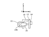
- light irradiation
- unit
- irradiation device
- Prior art date
- Legal status (The legal status is an assumption and is not a legal conclusion. Google has not performed a legal analysis and makes no representation as to the accuracy of the status listed.)
- Ceased
Links
Images











Classifications
-
- A—HUMAN NECESSITIES
- A61—MEDICAL OR VETERINARY SCIENCE; HYGIENE
- A61N—ELECTROTHERAPY; MAGNETOTHERAPY; RADIATION THERAPY; ULTRASOUND THERAPY
- A61N5/00—Radiation therapy
- A61N5/06—Radiation therapy using light
- A61N5/0613—Apparatus adapted for a specific treatment
- A61N5/0616—Skin treatment other than tanning
- A61N5/0617—Hair treatment
-
- A—HUMAN NECESSITIES
- A45—HAND OR TRAVELLING ARTICLES
- A45D—HAIRDRESSING OR SHAVING EQUIPMENT; EQUIPMENT FOR COSMETICS OR COSMETIC TREATMENTS, e.g. FOR MANICURING OR PEDICURING
- A45D20/00—Hair drying devices; Accessories therefor
- A45D20/04—Hot-air producers
-
- A—HUMAN NECESSITIES
- A45—HAND OR TRAVELLING ARTICLES
- A45D—HAIRDRESSING OR SHAVING EQUIPMENT; EQUIPMENT FOR COSMETICS OR COSMETIC TREATMENTS, e.g. FOR MANICURING OR PEDICURING
- A45D20/00—Hair drying devices; Accessories therefor
- A45D20/04—Hot-air producers
- A45D20/08—Hot-air producers heated electrically
- A45D20/10—Hand-held drying devices, e.g. air douches
- A45D20/12—Details thereof or accessories therefor, e.g. nozzles, stands
-
- A—HUMAN NECESSITIES
- A45—HAND OR TRAVELLING ARTICLES
- A45D—HAIRDRESSING OR SHAVING EQUIPMENT; EQUIPMENT FOR COSMETICS OR COSMETIC TREATMENTS, e.g. FOR MANICURING OR PEDICURING
- A45D19/00—Devices for washing the hair or the scalp; Similar devices for colouring the hair
- A45D2019/0033—Processes for treating the scalp
-
- A—HUMAN NECESSITIES
- A45—HAND OR TRAVELLING ARTICLES
- A45D—HAIRDRESSING OR SHAVING EQUIPMENT; EQUIPMENT FOR COSMETICS OR COSMETIC TREATMENTS, e.g. FOR MANICURING OR PEDICURING
- A45D2200/00—Details not otherwise provided for in A45D
- A45D2200/20—Additional enhancing means
- A45D2200/205—Radiation, e.g. UV, infrared
-
- A—HUMAN NECESSITIES
- A45—HAND OR TRAVELLING ARTICLES
- A45D—HAIRDRESSING OR SHAVING EQUIPMENT; EQUIPMENT FOR COSMETICS OR COSMETIC TREATMENTS, e.g. FOR MANICURING OR PEDICURING
- A45D2200/00—Details not otherwise provided for in A45D
- A45D2200/20—Additional enhancing means
- A45D2200/207—Vibration, e.g. ultrasound
-
- A—HUMAN NECESSITIES
- A61—MEDICAL OR VETERINARY SCIENCE; HYGIENE
- A61N—ELECTROTHERAPY; MAGNETOTHERAPY; RADIATION THERAPY; ULTRASOUND THERAPY
- A61N5/00—Radiation therapy
- A61N5/06—Radiation therapy using light
- A61N2005/0626—Monitoring, verifying, controlling systems and methods
-
- A—HUMAN NECESSITIES
- A61—MEDICAL OR VETERINARY SCIENCE; HYGIENE
- A61N—ELECTROTHERAPY; MAGNETOTHERAPY; RADIATION THERAPY; ULTRASOUND THERAPY
- A61N5/00—Radiation therapy
- A61N5/06—Radiation therapy using light
- A61N2005/0635—Radiation therapy using light characterised by the body area to be irradiated
- A61N2005/0643—Applicators, probes irradiating specific body areas in close proximity
- A61N2005/0644—Handheld applicators
-
- A—HUMAN NECESSITIES
- A61—MEDICAL OR VETERINARY SCIENCE; HYGIENE
- A61N—ELECTROTHERAPY; MAGNETOTHERAPY; RADIATION THERAPY; ULTRASOUND THERAPY
- A61N5/00—Radiation therapy
- A61N5/06—Radiation therapy using light
- A61N2005/065—Light sources therefor
- A61N2005/0651—Diodes
-
- A—HUMAN NECESSITIES
- A61—MEDICAL OR VETERINARY SCIENCE; HYGIENE
- A61N—ELECTROTHERAPY; MAGNETOTHERAPY; RADIATION THERAPY; ULTRASOUND THERAPY
- A61N5/00—Radiation therapy
- A61N5/06—Radiation therapy using light
- A61N2005/0658—Radiation therapy using light characterised by the wavelength of light used
- A61N2005/0662—Visible light
- A61N2005/0663—Coloured light
Definitions
- the present invention relates to a light irradiation apparatus that emits light for illuminating the scalp or hair.
- Patent Document 1 describes a hair dryer that blows warm air from a blowout port and that irradiates blue light toward the blowout direction.
- scalp a technique for irradiating a predetermined type of light to the scalp or hair (hereinafter referred to as scalp) has been studied. .
- the hair dryer described in Patent Document 1 has a suction port and a blowout port, and heats the air sucked from the suction port by a heater accommodated in the blower passage in the main body case and blows out as hot air from the blowout port.
- a light source that blows out air containing ions by providing an ion generator and irradiates blue light in the blowing direction is provided.
- Such a hair dryer irradiates blue light having a wavelength of 465 to 470 nm from the LED to sterilize skin resident bacteria in the hair.
- a light source for irradiating blue light in the blowing direction is provided. Blue light has a bactericidal effect that reduces or reverses the growth of bacteria, so it suppresses the growth of resident bacteria on hair that has been irradiated with blue light even if it is moisturized by air containing ions. To do.
- the distance from the LED light source to the scalp or the like is long, the range in which the light from the LED light source diffuses becomes wide, and the possibility that the light will enter the eye increases. If the blue light emitted from the LED light source enters the eyes, the eyes may be subjected to a certain stress due to the so-called blue light problem, and the long-term effects of such stress have been sufficiently verified. I can't say that.
- the object of the present invention has been made in view of such problems, and in a light irradiation apparatus that irradiates light to the scalp and the like, it is possible to increase the amount of light reaching the scalp and the like while suppressing the influence of light entering the eyes. It is in providing the technique of a light irradiation apparatus.
- a light irradiation apparatus outputs a light blowing unit for sending an air flow flowing in a first direction and a light beam for illuminating a scalp or hair as an irradiated unit.
- the light emitting unit is provided on the first direction side of the air blowing unit.
- the ratio of the amount of light that reaches the scalp closer to the scalp and the like increases, relatively It becomes possible to suppress the ratio of the amount of light entering.
- a light irradiation apparatus that can increase the amount of light reaching the scalp while suppressing the influence of light entering the eye in a light irradiation apparatus that irradiates light to the scalp and the like.
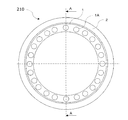
- FIG. 3 is a cross-sectional view taken along line AA in FIG. 2. It is a side view which shows the state before attaching the light irradiation apparatus of 2nd Embodiment to a hair dryer.
- FIG. 18 is a detailed cross-sectional view illustrating a first modification of the attachment portion in FIG. 17.
- FIG. 18 is a detailed cross-sectional view showing a second modification of the attachment portion in FIG. 17.
- It is explanatory drawing which shows the direction of the light irradiated from LED of the light irradiation apparatus of 2nd Embodiment.
- It is side surface explanatory drawing which shows the state seen from the horizontal direction of FIG.
- It is side surface sectional drawing which shows an example of the mounting substrate of 2nd Embodiment.
- It is a side surface fragmentary sectional view which shows 3rd Embodiment of this invention.
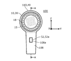
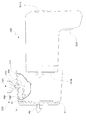
- FIG. 1 is an exploded perspective view of the light irradiation apparatus 100 according to the embodiment
- FIG. 2 is a front view of the light irradiation apparatus 100
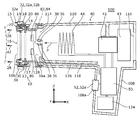
- FIG. 3 schematically shows a side cross section of the light irradiation apparatus 100.
- the direction X corresponds to the horizontal left-right direction
- the direction Y corresponds to the horizontal front-rear direction
- the direction Z corresponds to the vertical up-down direction
- the direction Y and the direction Z are orthogonal to the direction X, respectively.
- the direction X may be described as the left direction or the right direction
- the direction Y may be expressed as the forward direction or the rear direction
- the direction Z may be expressed as the upward direction or the downward direction.
- the light irradiation apparatus 100 has a blower 40 for sending an air flow 42 flowing in the first direction P and a light flux for illuminating the scalp or hair that is the irradiated part 70.
- the light emitting unit 10 that outputs 28 is provided on the first direction P side of the air blowing unit 40.
- the temperature of the irradiated portion 70 rises if the irradiated portion 70 is irradiated with the light beam 28 with the light irradiation device 100 placed on the head. Further, it is conceivable that the temperature of the irradiated portion 70 is raised by the light irradiation device 100 itself generating heat during use. Therefore, in the light irradiation device 100, the air blowing unit 40 is configured to send the air flow 42 toward the irradiated unit 70. The irradiated portion 70 receives the air flow 42 so that the temperature rise can be mitigated. In addition, since the irradiated portion 70 receives the unwarmed cool breeze, the user's tension is released and the blood flow is improved, so that a synergistic effect with receiving the light flux 28 on the scalp can be expected.
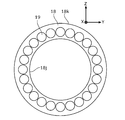
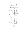
- FIGS. 4 is a front view of the cover member 18, FIG. 5 is a side view thereof, and FIG. 6 is a rear view thereof.
- the plurality of light emitting elements 20 are in direct contact with the scalp or the hair that is the irradiated portion 70, foreign substances such as sebum may adhere to the plurality of light emitting elements 20 and the surfaces of the plurality of light emitting elements 20 may become cloudy. It is conceivable that the amount of light output decreases when the surfaces of the plurality of light emitting elements 20 are clouded. For this reason, it is desirable that the plurality of light emitting elements 20 do not directly contact the irradiated portion 70.
- the light emitting unit 10 is provided with a replaceable cover member 18 through which the light flux 28 is transmitted.
- the cover member 18 may be provided with an engaging portion that can be easily attached and detached.
- the cover member 18 has a plurality of projecting portions 19 projecting in the first direction P side.
- the protrusion 19 is divided between the hairs, and the tip of the protrusion 19 approaches the scalp, so that the light beam 28 can efficiently reach the scalp.
- the tip of the protrusion 19 hits the scalp, it is possible to apply an appropriate stimulus to the scalp and promote blood flow.
- the cover member 18 is provided with a recess 19 b that houses at least a part of the plurality of light emitting elements 20.
- the recess 19b may be provided corresponding to the protrusion 19.
- the cover member 18 is formed of a material that attenuates ultraviolet light. In this case, since the ultraviolet light contained in the light flux 28 transmitted through the cover member 18 is small, the user can use it with peace of mind.
- the cover member 18 is moved in the first direction from the retreat area 18a and the retreat area 18a retreating toward the blower section 40 in the front-rear direction which is the first direction P. And an advance region 18b that advances forward at P.
- the retreat area 18 a and the advance area 18 b of the cover member 18 can be arranged corresponding to the curved shape C of the irradiated portion 70.
- FIG. 8 is a front view of the hood member 15, and FIG. 9 is a side view thereof.
- the light emitting unit 10 is provided with the hood member 15 that surrounds the light flux 28 on the first direction P side.
- the hood member 15 By providing the hood member 15, the amount of light leaking to the outside can be reduced.
- the light quantity which leaks outside can be further reduced by providing the hood member 15 so that the to-be-irradiated part 70 can be contacted.
- the hood member 15 may be provided so as to protrude forward from the protruding portion 19 of the cover member 18.
- the hood member 15 is provided with a retreat area 15a corresponding to the retreat area 18a of the cover member 18 and a forward area 15b corresponding to the forward area 18b.
- the advance region 15b advances forward in the first direction P from the retract region 15a.
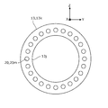
- the plurality of light emitting elements 20 will be described with reference to FIGS. 10 is a front view of the plurality of light emitting elements 20 attached to the substrate 13, and FIG. 11 is a side view thereof. From the viewpoint of the convenience of the user, it is desirable that the light irradiation device can irradiate a light beam over a wide range. Therefore, in the light irradiation device 100, the light emitting unit 10 includes a plurality of light emitting elements 20, as shown in FIG. As the plurality of light emitting elements 20, for example, LEDs (light emitting diodes) or LDs (diode lasers) can be used.
- LEDs light emitting diodes
- LDs diode lasers
- the plurality of light emitting elements 20 are arranged so as to surround the air flow 42.
- the plurality of light emitting elements 20 may be arranged in a circular shape, an oval shape, or a polygonal shape so as to surround the air flow 42.
- the irradiated part is often curved. For this reason, it is desirable that the position of each light emitting element is set corresponding to the curved shape of the irradiated portion. Therefore, in the light irradiation device 100, as shown in FIG. 11, the plurality of light emitting elements 20 are, in the front-rear direction that is the first direction P, the light emitting elements 20a that recede toward the air blowing section in the first direction P; And the light emitting element 20b advanced in the first direction from the retreating light emitting element 20a.
- each of the plurality of light emitting elements 20 is arranged so as to change the position in the front-rear direction so as to follow the curved shape C of the head.
- the light emitting element 21 in the vicinity of the center in the direction Z (vertical direction) is in the front-rear direction, which is the first direction P, from the light emitting elements 22 on both sides (upper and lower sides). It is set back to the rear side. The difference in distance from the head surface of each of the plurality of light emitting elements 20 is reduced, and the light flux 28 can be effectively irradiated.
- the amount of light received in the irradiated part is small in each part in the irradiated part. Therefore, in the light irradiation device 100, at least a part of the plurality of light emitting elements 20 is provided to be inclined with respect to the front-rear direction that is the first direction P. That is, in the light irradiation device 100, at least some of the plurality of light emitting elements 20 are provided such that the optical axis is inclined with respect to the front-rear direction. In the light irradiation apparatus 100, as an example, the plurality of light emitting elements 20 are inclined inward so that their optical axes intersect at the front. The plurality of light emitting elements 20 may be inclined outward so that their optical axes open forward.
- Such an inclination direction can be set corresponding to the directivity of the light emitting element.
- Such an inclination can be set in a range of 3 degrees to 30 degrees, for example.
- the optical axes of the plurality of light emitting elements 20 are provided so as to be inclined inward by 3 degrees with respect to the front-rear direction.
- the light irradiation device 100 As shown in FIG. 3, at least a part of the plurality of light emitting elements 20 is arranged in a region through which the air flow 42 passes. That is, the plurality of light emitting elements 20 are arranged in a range extending forward from the delivery port 114. In this case, the plurality of light emitting elements 20 are cooled by the air flow 42 delivered from the delivery port 114, and the temperature rise is suppressed.
- the light emission part 10 is the range through which the airflow 42 passes at least one part of the electronic component 14 electrically connected to either of the some light emitting elements 20.
- the light emission part 10 is the range through which the airflow 42 passes at least one part of the electronic component 14 electrically connected to either of the some light emitting elements 20.
- the current limit is configured to cut off or reduce the current supplied to the light emitting unit 10.
- the unit 32 is provided. That is, in the light irradiation device 100, the light emitting unit 10 is energized and outputs the light flux 28 in a state where the light emitting unit 10 is close to the irradiated unit 70, and the energization is substantially stopped when moving away from the irradiated unit 70. Is configured to do.
- the current limiting unit 32 may be configured to detect a distance from the light emitting unit 10 and to control energization to the light emitting unit 10 according to the detected distance.
- the current limiting unit 32 may be configured to energize the light emitting unit 10 when the light emitting unit 10 contacts the irradiated portion 70 or its periphery. When the light emitting unit 10 moves away from the head, the output of the light beam 28 automatically decreases, so that the possibility of the light beam 28 entering the eye can be reduced.
- the description of the current limiting unit 32 is omitted in FIGS.
- the light irradiation apparatus may be used for a predetermined time for each irradiated portion by dividing the head into a plurality of irradiated portions.
- the use time for each irradiated portion is preferably in the range of 3 seconds to 30 seconds, more preferably in the range of 5 seconds to 20 seconds.
- the use time for each irradiated part is short when the luminous flux of the light irradiation device is large, and is long when the light flux is small. It is convenient for the user if a signal is output for such usage time.
- the light irradiation device 100 includes a signal output unit 34 configured to output a signal that can be perceived by the user at a predetermined timing, as shown in FIG.
- the signal output unit may output a beep sound 34e that is a signal every set time (for example, 10 seconds).
- the user can switch the use position at the timing of the signal.
- the signal is not particularly limited as long as it can be perceived by the user.
- the illustration of the signal output unit 34 is omitted in FIGS.
- the signal output unit 34 outputs a signal using at least one of sound, vibration, and light at a timing when a predetermined time has elapsed from the start of supply of current to the light emitting unit 10. It is configured. As an example, the signal output unit 34 may output a beep sound 34e that is a signal at a timing when a set time (for example, 5 seconds) has elapsed since the start of supply of current to the light emitting unit 10. The user can switch the use position at the timing of the beep sound 34e. In this case, the usage time for each irradiated portion can be easily aligned.
- the light irradiation device 100 the light emitting unit 10 is provided so as to be attachable to and detachable from the air blowing unit 40, and the air blowing unit 40 includes a first contact part 36 for supplying current to the light emitting unit 10.
- the light emitting unit 10 has a second contact part 38 that is electrically connected to the first contact part 36 in a state of being attached to the air blowing part 40.
- the light irradiation device 100 can be stored separately in the light emitting unit 10 and the air blowing unit 40. Further, the light irradiation device 100 can supply power to the light emitting unit 10 via the first contact part 36 and the second contact part 38 only by supplying power to the air blowing part 40 side by attaching the light emitting part 10 to the air blowing part 40.
- the blower 40 includes a housing 110, a grip 108, a suction port 116, a delivery port 114, an impeller 43, a motor 41, a heater 44, a control unit 50, and a switch.
- Part 52 wiring passage part 118, first contact part 36, power supply part 124, and first engagement part 82.
- the housing 110 is a housing for housing and holding main components of the air blowing unit 40 therein.
- the casing 110 is a hollow, substantially cylindrical member, and can be formed from a resin material by a molding process.
- the grip part 108 is a part for the user to hold with the hand, and is attached so as to protrude downward from the outer peripheral lower surface near the rear part of the housing 110.
- the grip part 108 may be connected to the housing 110 via hinge means that enables bending.
- the suction port 116 is an opening for introducing air for blowing air from the atmosphere space into the housing 110, and is provided on the rear side of the housing 110, for example.
- the suction port 116 may be provided with a mesh member (not shown) that suppresses entry of foreign matter.
- the delivery port 114 is an opening for delivering the air flow 42 and is provided on the front side of the housing 110.
- the delivery port 114 may be provided with a mesh member (not shown) that suppresses entry of foreign matter.
- the impeller 43 is a blade member for extruding the rear air forward by rotating, and can be formed from a resin material, for example, by a molding process.
- the impeller 43 is provided in the housing 110 on the front side of the suction port 116.
- the motor 41 is an electric motor for rotationally driving the impeller 43, and rotates when current is supplied from the control unit 50.
- the motor 41 is provided on the front side of the impeller 43 in the housing 110, and the rotation shaft (not shown) of the motor 41 is fixed to the center of the impeller 43.
- the heater 44 is an electric heater for heating the air flow pushed out by the impeller 43, and generates heat when current is supplied from the control unit 50.
- the heater 44 is provided on the front side of the motor 41 of the housing 110.
- the control unit 50 is configured to control electric power supplied from the power supply unit 124 and supply current to each of the motor 41, the heater 44, and the light emitting unit 10 according to the state of the switch unit 52.
- the control unit 50 is accommodated and fixed in the grip unit 108, for example.
- the control unit 50 may be accommodated in the housing 110.
- a means for limiting the amount of light emitted from the light emitting unit 10 may be provided from the viewpoint of limiting excessive irradiation to the irradiated portion 70.
- the control unit 50 may be configured to limit power supply to the light emitting unit 10 based on a value obtained by a predetermined calculation using a supply current and a supply time to the light emitting unit 10 as parameters.
- the switch unit 52 is a member that switches the operation mode of the light irradiation apparatus 100.
- the switch unit 52 can include a mechanical switch having a mechanical contact and an electronic switch that detects electronic contact and switches electronically.
- the switch part 52 is attached to the grip part 108 so that the protrusion part 52a protrudes into the opening 108a on the front side of the grip part 108.
- the switch part 52 is configured to switch between a plurality of modes by pushing the protruding part 52a backward. For example, from the entire off state, current is supplied to the motor 41 by the first push and air blowing is started, current is supplied to the light emitting unit 10 by the second push and light emission is started, and light is emitted by the third push.
- the switch unit 52 can include a plurality of electrical switches.
- the switch unit 52 may include a light emission control switch for starting or stopping power supply to the light emitting unit 10, and the light emission control switch is configured to start or stop power supply according to the attitude of the light irradiation device 100. May be.
- the light emission control switch may be configured to start power supply to the light emitting unit 10 in a predetermined posture (for example, a posture in which the light emitting unit 10 faces the head).
- the first contact part 36 has a contact for electrical connection with the second contact part 38, and is electrically connected to the output part of the control part 50 by an electric cable 126.
- the first contact portion 36 is provided, for example, on the outer peripheral portion of the first engagement portion 82.
- the wiring passage portion 118 is a passage for protecting the electric cable 126 connected from the control unit 50 to the light emitting unit 10 from the heat of the heater 44.
- the wiring passage portion 118 is provided below the housing 110 in order to accommodate the electric cable 126 that connects the control portion 50 to the first contact portion 36.
- the power supply unit 124 is an electric circuit for sending electric power supplied from a power cable (not shown) to the control unit 50, and is housed and fixed in the grip unit 108.
- the power supply unit 124 may include a rectifier circuit and a smoothing circuit.
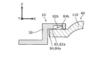
- FIG. 12 is an enlarged cross-sectional view of the first engaging portion 82 and a second engaging portion 84 described later.
- the 1st engaging part 82 is an attachment / detachment mechanism for attaching the light emission part 10 to the ventilation part 40 so that attachment or detachment is possible.
- the first engaging portion 82 includes a fitting outer peripheral surface 82a provided in front of the housing 110 and a claw portion 82b provided on the fitting outer peripheral surface 82a.
- the fitting outer peripheral surface 82a is formed with a smaller diameter than, for example, a region on the rear side thereof.
- One or a plurality of (for example, two) claw portions 82b may be provided on the fitting outer peripheral surface 82a.
- the fitting outer peripheral surface 82 a is configured to be fitted to the fitting inner peripheral surface 84 a of the second engaging portion 84.
- the claw portion 82 b is configured to engage with the step portion 84 b of the second engagement portion 84.
- the light emitting unit 10 includes a housing 30, a vent 86, a cover member 18, a hood member 15, a substrate 13, an electronic component 14, a plurality of light emitting elements 20, and second contacts. Part 38 and a second engagement part 84.
- the housing 30 is a hollow, substantially cylindrical member for accommodating and holding main components of the light emitting unit 10 therein.
- the housing 30 can be formed from a resin material by a molding process, for example.
- the vent 86 is an opening that communicates the inside and the outside of the housing 30, and one or a plurality of (for example, four) vent holes 86 are formed on the outer periphery of the housing 30. Providing the air vent 86 facilitates ventilation of the air inside the housing 30 and suppresses the temperature rise of the irradiated portion 70.
- the cover member 18 is a substantially disk-shaped member provided perpendicular to the front-rear direction (direction X), and has an inner peripheral portion 18j and an outer peripheral portion 18k.
- the cover member 18 can be formed by, for example, a molding process from a resin material having good light transmittance.
- a plurality of (for example, 24) projecting portions 19 projecting forward are provided on the front side of the cover member 18.
- the protruding portion 19 has a shell shape in which a hemisphere is coupled to the tip of the cylinder.
- a plurality of (for example, 24) recesses 19 b that are recessed forward are provided on the rear side of the cover member 18.
- the recesses 19b accommodate the tip portions of the plurality of light emitting elements 20.
- the concave portion 19 b corresponds to the protruding portion 19.
- the hood member 15 is a hollow cylindrical member extending in the front-rear direction (direction X), and has an inner peripheral portion 15j and an outer peripheral portion 15k.
- the hood member 15 can be formed from a resin material by a molding process, for example.
- the hood member 15 may be formed of a material having low light transmittance.
- a reflective surface may be formed on the inner surface of the hood member 15.
- the hood member 15 may be formed so as to be attached to and detached from the light emitting unit 10 in a state of being integrated with the cover member 18.
- the substrate 13 is a substantially disc-shaped printed wiring board provided perpendicularly to the front-rear direction, and has an inner peripheral portion 13j and an outer peripheral portion 13k.
- the substrate 13 has an outer peripheral portion 13k fixed to the step portion of the housing 30 by screwing or bonding.
- the electronic component 14 may include a resistor that limits a current flowing through the plurality of light emitting elements 20, a capacitor that smoothes the voltage, and the like.
- the electronic component 14 is fixed to the front surface portion and the rear surface portion of the substrate 13 by soldering.
- the plurality of light emitting elements 20 include a plurality (for example, 24) of LEDs 20 m arranged on the front side of the substrate 13 at substantially equal intervals in the circumferential direction.
- LED20m In the light irradiation apparatus 100 of embodiment, LED with a wavelength of 620-670 nm (red) is selected. For example, it has been found that the use of red light of 638 nm with an amount of light of 1 J to 1.5 J per square centimeter is effective in activating the subcutaneous tissue.
- the second contact portion 38 has a contact for electrical connection with the first contact portion 36, and is electrically connected to the plurality of light emitting elements 20 by the electric cable 128. ing.
- the second contact portion 38 is provided, for example, on the inner peripheral portion of the second engagement portion 84. In a state where the light emitting unit 10 is attached to the blower unit 40, the two contacts of the second contact unit 38 are electrically connected to the two contacts of the first contact unit 36.
- the 2nd engaging part 84 is an attachment / detachment mechanism for attaching the light emission part 10 to the ventilation part 40 so that attachment or detachment is possible, as shown in FIG.
- the second engaging portion 84 includes a fitting inner peripheral surface 84a provided at the rear of the housing 30 and a stepped portion 84b formed on the fitting inner peripheral surface 84a.
- One or a plurality of (for example, two) stepped portions 84b may be provided on the fitting inner peripheral surface 84a.
- the fitting inner peripheral surface 84 a is configured to fit to the fitting outer peripheral surface 82 a of the first engaging portion 82.
- the stepped portion 84b is configured to engage with the claw portion 82b of the first engaging portion 82.
- the current limiting unit 32 is configured to cut off or reduce the current supplied to the light emitting unit 10 when the light emitting unit 10 is separated from the irradiated unit 70 by a predetermined distance or more.
- the current limiting unit 32 includes a sensor unit 32a, and is configured to cut off or reduce the current supplied to the light emitting unit 10 according to the state of the sensor unit 32a.
- a limit switch whose output state changes corresponding to mechanical contact, or a distance sensor using light or sound waves can be employed.
- the sensor part 32 a is attached to the outer peripheral part of the housing 30.
- the sensor part 32a has a front end part 32e protruding forward, and incorporates a limit switch 32b that is turned on when the front end part 32e is pushed in contact with the irradiated part 70.
- the limit switch 32 b is connected in series with the light emitting unit 10, and is off when not in use, and is turned on when the tip 32 e comes into contact with the irradiated portion 70 and energizes the light emitting unit 10.
- the cue output unit 34 is configured to output a cue using at least one of sound, vibration, and light at a predetermined timing.
- the signal output unit 34 is provided in the light emitting unit 10 or the air blowing unit 40.
- the signal output unit 34 is provided on the outer peripheral portion of the housing 30 as shown in FIG. 3.
- the signal output unit 34 is configured to output a signal at a timing when a predetermined time has elapsed from the start of supply of current to the light emitting unit 10. As shown in the block wiring diagram of FIG.
- the signal output unit 34 includes a timer unit 34a whose output state changes from OFF to ON after a set time set after the start of energization of the light emitting unit 10, and a timer unit 34a Buzzer means 34b for generating a beep sound 34e when the output state is ON.
- the timer means 34a becomes active when the light emitting unit 10 is energized, and starts counting time.
- the timer means 34a energizes the buzzer means 34b when a predetermined time count elapses and generates a beep sound 34e.
- the timer means 34a is reset and the buzzer means 34b pauses. Further, when the light emitting unit 10 is energized, the timer means 34a becomes active, and the signal output unit 34 repeats the above operation.
- the 1st usage pattern uses only the light emission function of the light emission part 10 by making the ventilation part 40 into a non-operation state. This mode is referred to as a first mode.
- the switch unit 52 is operated to switch the light irradiation device 100 to the first mode. In this state, the current limiting unit 32 is working, and the light emitting unit 10 is in a non-light emitting state.
- the light emitting portion 10 When the light emitting unit 10 is brought close to the head and the tip 32e comes into contact with the irradiated portion 70, the light emitting portion 10 is energized to start light emission and irradiate the irradiated portion 70 with the light flux 28. At the same time, the timer means 34a is activated. For example, when a set 10 seconds elapses, a beep sound 34e is generated from the buzzer means 34b. In response to the beep sound 34e, the user once separates the light emitting unit 10 from the head. In this state, the light emission and beep sound 34e are stopped.
- the same operation as described above is repeated. By repeating these operations, the light beam 28 can be received in a desired range of the head.
- Second usage pattern The second usage pattern is used together with the light emitting function of the light emitting section 10 with the air blowing unit 40 in a state of blowing unheated cool air.
- This mode is referred to as a second mode.
- the switch unit 52 is operated to switch the light irradiation device 100 to the second mode.
- the unheated air flow 42 sent out by the blower 40 passes through the hole 16 of the light emitting unit 10 and is discharged from the outlet 16b.
- the air flow 42 hits the head.
- the light emitting portion 10 is energized to start light emission and irradiate the irradiated portion 70 with the light flux 28. That is, in this state, the non-heated air flow 42 and the light flux 28 simultaneously strike the irradiated portion 70.
- the beep sound 34e is generated at a predetermined timing by operating the signal output unit 34.
- the user repeats the same operation as described above by placing the light emitting unit 10 on the irradiated portion 70 at another position on the head. By repeating these operations, the user can simultaneously receive the unheated air flow 42 and the luminous flux 28 in a desired range of the head.
- the third usage pattern is used together with the light emitting function of the light emitting section 10 in a state in which the warm air that has heated the air blowing section 40 is blown.
- This mode is referred to as a third mode.
- the switch unit 52 is operated to switch the light irradiation device 100 to the third mode.
- the heated air flow 42 sent out by the blower 40 passes through the hole 16 of the light emitting unit 10 and is discharged from the outlet 16b.
- the following operation is the same as in the second usage pattern, and by repeating this operation, the air flow 42 and the luminous flux 28 heated to the desired range of the head can be simultaneously received.
- the 4th usage pattern uses only the ventilation function of the ventilation part 40 by making the light emission part 10 into a non-operation state.
- the light emitting unit 10 may be used in a state where it is detached from the air blowing unit 40 or may be used in a state where it is attached.
- This mode is referred to as a fourth mode.
- the switch unit 52 is operated to switch the light irradiation device 100 to the fourth mode.
- the non-heated or heated air flow 42 sent out by the air blowing unit 40 passes through the hole 16 of the light emitting unit 10 and is discharged from the outlet 16b.
- the fourth mode of use the user can receive an unheated or warmed air stream 42 in the desired range of the head.
- the signal output unit 34 may be used or may not be used.
- the light irradiation device 100 may be used in a state where at least a part of the front side which is the first direction P side of the light emitting unit 10 is in contact with the head.
- a part of the light irradiation device 100 can be used in a state of being in contact with the head. By using in this way, the amount of light leaking to the outside can be reduced.
- the light irradiation device 100 includes a blower 40 for sending out an air flow 42 flowing in the first direction P, and a light emitting unit 10 that outputs a light beam 28 for illuminating the scalp or hair as the irradiated portion 70.
- the light emitting unit 10 is provided on the first direction P side of the air blowing unit 40. With this configuration, the irradiated portion 70 can receive the light flux 28 from the light irradiation device 100.
- the air blowing unit 40 is configured to send the air flow 42 toward the irradiated unit 70, the irradiated unit 70 can receive the air flow 42 together with the light flux 28.
- the cover member 18 through which the light flux 28 is transmitted is provided in the light emitting unit 10 in a replaceable manner, so that the possibility that the plurality of light emitting elements 20 are in direct contact with the irradiated portion 70 can be reduced.
- the cover member 18 since the cover member 18 has a plurality of protrusions 19 that protrude in the first direction P side, the protrusions 19 can be divided between the hairs to reduce the density of the hairs. . Moreover, in the light irradiation apparatus 100, since the cover member 18 is provided with the recessed portions 19b for accommodating at least a part of the plurality of light emitting elements 20, the distal end portion of the light emitting elements 20 can be accommodated in the recessed portions 19b. Moreover, in the light irradiation apparatus 100, since the cover member 18 is formed of a material that attenuates ultraviolet light, the cover member 18 can attenuate the ultraviolet light of the light flux 28.
- the cover member 18 is moved forward in the first direction P from the retracted area 18 a and the retracted area 18 a that is retracted toward the blower 40 in the front-rear direction that is the first direction P. Since the region 18b is included, the cover member 18 can correspond to the curved shape of the irradiated portion 70.
- the hood member 15 that surrounds the light flux 28 on the first direction P side is provided in the light emitting unit 10, so that the hood member 15 can cover the light flux 28.
- the light emitting unit 10 includes a plurality of light emitting elements 20, and thus the light emitting unit 10 can emit light by the plurality of light emitting elements 20.
- the plurality of light emitting elements 20 are arranged in the front-rear direction, which is the first direction P, in the first direction P than the light emitting elements 20 a that are retracted toward the blower side and the light emitting elements 20 a that are retracted.
- the plurality of light emitting elements 20 can correspond to the curved shape of the irradiated portion 70 since the light emitting elements 20b moving forward in one direction are included.
- the plurality of light emitting elements 20 is provided to be inclined with respect to the front-rear direction that is the first direction P. Therefore, the plurality of light emitting elements 20 are inclined from the first direction P.
- a light emitting device can be included.
- the plurality of light emitting elements 20 are disposed in a region through which the air flow 42 passes. Therefore, the plurality of light emitting elements 20 include light emitting elements disposed in a region through which the air flow 42 passes. Can be included.
- the light emitting unit 10 is disposed in a range in which at least a part of the electronic component 14 electrically connected to any of the plurality of light emitting elements 20 passes through the air flow 42.
- 10 may include electronic components disposed in the region through which the airflow 42 passes.
- the light irradiation apparatus 100 includes the current limiting unit 32 configured to cut off or reduce the current supplied to the light emitting unit 10 when the light emitting unit 10 is separated from the irradiated unit 70 by a predetermined distance or more. When away from the irradiation unit 70, the current of the light emitting unit 10 can be changed.
- the light irradiation apparatus 100 includes the cue output unit 34 configured to output a cue that can be perceived by the user at a predetermined timing, the user can perceive the arrival of the predetermined timing by the cue. .
- the signal output unit 34 is configured to output a signal using at least one of sound, vibration, and light at a timing when a predetermined time has elapsed from the start of supply of current to the light emitting unit 10. Therefore, the user can perceive the arrival of the timing when a predetermined time has elapsed due to at least one of sound, vibration, and light.
- the light emitting unit 10 is provided so as to be attachable to and detachable from the air blowing unit 40, and the air blowing unit 40 includes a first contact part 36 for supplying current to the light emitting unit 10.
- the light emitting unit 10 includes the second contact part 38 that is electrically connected to the first contact part 36 in a state where the light emitting part 10 is attached to the air blowing part 40, and thus the light irradiation device 100 removes the light emitting part 10. be able to.
- Modification 1 In the light irradiation apparatus 100, the example using the LED that outputs red light has been described, but the present invention is not limited thereto. For example, LEDs that output green or blue light may be used, or LEDs that output light of different colors may be used in combination.
- Modification 2 In the light irradiation apparatus 100, the example in which the LED or the LD is used as the light emitting element has been described, but the present invention is not limited thereto.
- other types of light emitting elements such as organic EL elements may be used.
- the light irradiation apparatus of the present invention may be provided with means for sending air containing negative ions, means for sending mist obtained by atomizing a liquid such as water or cosmetic liquid, and the like.
- the light irradiation devices 210, 220, and 230 according to the second to fourth embodiments of the present invention will be described.
- cell activity is improved by the light emitted from the light emitting diode (LED)
- LED light emitting diode
- fibroblasts grow by the light emitted from the LED
- growth factors are synthesized, collagen is produced, and angiogenesis is increased.
- LED irradiation has an effect on the healing of skin tissue and hair.
- the light irradiation devices 210, 220, and 230 include a plurality of light emitting diodes (1 ⁇ / b> A: hereinafter referred to as “LED”) and can be attached to and detached from the beauty instruments 180 and 280.
- LED light emitting diodes
- the LED emits light of any wavelength of 620 to 670 nm (red), 450 to 480 nm (blue), 560 to 600 nm (yellow), 500 to 530 nm (green), or all wavelengths. preferable.
- beauty equipment refers to a hair dryer for preparing a hairstyle, and a facial equipment for activating facial skin to make so-called “skin skin” (for example, a facial roller or other various facial equipment). It is used in the meaning including.
- the plurality of LEDs 1A are arranged in a closed shape (for example, a circle or an ellipse) constituted by a curve, and light emitted from each LED 1A has the shape described above. It is preferable to proceed in a direction inclined toward the inner region.
- a spray device 215 that can be attached to and detached from the light irradiation device 220 is provided.
- the spray device 215 includes a liquid storage unit 15A and the liquid storage unit 15A. It is preferable to have a spraying portion 15B that sprays the liquid stored in the container (for example, a so-called “beauty hair” liquid) in the form of a mist.
- Beauty instrument 180 is preferably a hair dryer.
- Beauty device 280 is preferably a facial device (for example, a facial roller or other various facial devices).
- the light irradiation devices 210, 220, and 230 are configured to be attachable to and detachable from the beauty instruments 180 and 280, the light irradiation devices 210, 220, and 230 that can be attached to an existing hair dryer can be easily provided. Can be manufactured. Therefore, the present invention can be applied without significantly modifying an existing hair dryer or the like.
- the plurality of LEDs 1A provided in the light irradiation devices 210, 220, and 230 are arranged in a circle (including an ellipse), and light emitted from each LED 1A is directed toward the inside in the radial direction of the circle. If it is configured to travel in an inclined direction, the light emitted from the LED 1A does not reach the eyeball of the user of the beauty tool 180, 280 of the present invention. Therefore, it is prevented that a user's eyeball is damaged by LED irradiation light.
- the spraying device 215 is attached to and detached from the light irradiation device 220, and the spraying device 215 sprays a liquid (for example, a so-called “hairdressing liquid”) in the form of a mist.
- a liquid for example, a so-called “hairdressing liquid”
- the spraying device 215 sprays a liquid (for example, a so-called “hairdressing liquid”) in the form of a mist.
- the present invention can be applied not only to a hair dryer but also to a facial device (for example, a facial roller or other various facial devices).
- a facial device for example, a facial roller or other various facial devices.
- the hair dryer is illustrated as a beauty instrument.
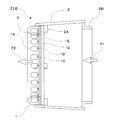
- the light irradiation device 210 includes a substantially cylindrical case portion 2 formed of an electrically insulating synthetic resin material and a plurality of LEDs 1A arranged in a circular shape, and the front end of the case portion 2 (see FIG. 15). 1 on the left side).
- an annular cover 3 made of a transparent synthetic resin material is attached to the front end (left end portion of FIG. 14) of the case portion 2, and the plurality of LEDs 1 ⁇ / b> A are covered with the cover 3. Yes.
- the LED unit 1 includes a plurality of LEDs 1 ⁇ / b> A and a member for attaching the LEDs 1 ⁇ / b> A to the front end of the case unit 2.
- FIG. 16 The detailed configuration of the LED unit 1 will be described with reference to FIGS.
- a plurality of LEDs 1A are respectively installed on a mounting board 1C via energization terminals 1B, and a heat insulating plate (not shown) is interposed between the LED 1A and the mounting board 1C.
- the mounting substrate 1C, the heat insulating plate (not shown), and a support member 1D described later are annular plate members, and a plurality of LEDs 1A are installed on the mounting substrate 1C at approximately equal intervals.
- the mounting substrate 1C on which the plurality of LEDs 1A are installed is fixed to the support member 1D via the spacer 1E. It is fixed to the LED mounting portion 2A provided in the vicinity of the front end (in the vicinity of the left end in FIG. 16) of the case portion 2 formed in a substantially cylindrical shape.
- the supporting member 1D is fixed to the LED mounting portion 2A by a known means such as a screw (not shown) at a plurality of circumferential positions (for example, four positions).
- An annular cover 3 formed of a transparent synthetic resin material is disposed so as to cover a plurality of LEDs 1A arranged in an annular shape, and the cover 3 is arranged at an inner peripheral side edge and an outer peripheral side edge. It is attached to the support member 1D at a plurality of locations. It is also possible to fix the outer peripheral end of the cover 3 to the front end (left end in FIG. 16) of the case 2 and the inner peripheral end to the support member 1D.
- the rear end (right side in FIGS. 14 and 16) of the case portion 2 is the attachment side to the beauty tool 180, and the attachment portion 2 ⁇ / b> B to the hair dryer is formed near the rear end of the case portion 2.
- the attachment portion 2B to the hair dryer will be described later with reference to FIGS.
- each of the LEDs 1A having a wavelength of 620 to 670 nm (red), 450 to 480 nm (blue), 560 to 600 nm (yellow), and 500 to 530 nm (green). Can be selected.
- any one type of wavelength LED may be selected, or a plurality of types of wavelength LEDs may be selected and attached to the light irradiation device 210.
- LEDs of all types of wavelengths may be selected and attached to the light irradiation device 210.
- FIG. 17 A state in which the light irradiation device 210 is attached to the beauty tool 180 is shown in FIG.
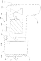
- a beauty tool 180 is provided with the light irradiation device 210 described with reference to FIGS. 14 to 16 in the vicinity of the hot air / cold air outlet 101B.
- a beauty instrument 180 shown in FIG. 17 has a feature that includes a mounting structure of the light irradiation device 210 and a power supply mechanism to the light irradiation device 210.
- air is sucked from the suction port 101A by the rotation of the blower fan 103, and the sucked air is blown to the heater 105 side.
- the air F3 blown to the heater 105 side is indicated by an arrow.
- heated or unheated air blows out from the outlet 101B to the light irradiation device 210 side, passes through the inside of the light irradiation device 210 (air passage), and the LED unit 1 Air is blown from the side (left side in FIG. 17) toward the user's hair (arrow F5).
- the beauty tool 180 to which the light irradiation device 210 is attached warm air or cold air is blown toward the user's hair (beauty target) and at the same time, light of a specific wavelength from the LED 1A. Is applied to the scalp of the user of the beauty tool 180. That is, the user can enjoy the hair-styling effect by the beauty tool 180 and the scalp improvement effect by the LED irradiation of the light irradiation device 210 at the same time, and can efficiently obtain the beauty effect.
- a portion indicated by an attachment location B is a location where the light irradiation device 210 is attached to the beauty tool 180, and will be described below with reference to FIGS.
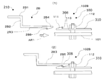
- a mounting portion 2B is provided in the vicinity of the rear end portion of the light irradiation device 210 (in the vicinity of the right end portion in FIGS. 14, 16, and 17).
- the mounting portion 2B is formed integrally with the case portion 2, and includes a main body side portion 2B1 of the case portion 2, a vertical portion 2B2 extending substantially vertically inward in the radial direction from the main body side portion 2B1, and a vertical portion 2B2.
- the horizontal portion 2B3 extends in the axial direction (horizontally) from the radially inner end portion (lower end in FIG. 18 (1)) to the light irradiation device 210 side (right side in FIG. 18 (1)).
- a protrusion 2B4 protruding inward in the radial direction is formed.
- An electrode 2B5 is embedded inside the protrusion 2B4 in the radial direction (downward in FIG. 18A), and the operation power is sent to the LED unit 1 of the light irradiation device 210 via the electrode 2B5. .
- a plurality of mounting portions 2B (for example, four locations) are provided at substantially equal intervals in the circumferential direction. However, at least one electrode 2B5 may be provided. Since a plurality of mounting portions 2B are provided at substantially equal intervals in the circumferential direction (for example, four locations), the horizontal portion 2B3 also extends in the axial direction (left and right directions in FIGS. 18 and 19) in a part of the circumferential direction. ing. It does not extend in the axial direction over the entire circumferential direction.
- a mounting portion 102B on the beauty tool 180 side is provided in the vicinity of the front end portion (the left end portion in FIG. 18 (1)) of the beauty tool 180.
- a locking member 310 is provided on the outer peripheral side in the vicinity of the front end of the main body case 101, and the locking member 310 extends substantially parallel to the axial direction of the beauty tool 180 by the fastening member 112.
- a protrusion 111 protruding outward in the radial direction is formed at the front end (on the light irradiation device 210 side) of the locking member 310.
- a spacer 113 is interposed between the locking member 310 and the main body case 101, and when the light irradiation device 210 is attached, the displacement amount can be absorbed when the locking member 310 is elastically deformed in the radial direction. Yes.
- an electrode 308 is embedded on the front side of the protrusion 111 (right side in FIG. 18 (1)). Electric power is supplied to the electrode 308 from a power supply on the beauty instrument 180 side through a circuit (not shown).
- the entire attachment part on the beauty instrument 180 side constituted by the locking member 310 and the like is indicated by the attachment part 102B.
- the attachment part 102B by the side of the beauty instrument 180 is formed in multiple places (for example, four places) at substantially equal intervals in the circumferential direction corresponding to the attachment part 2B by the side of the light irradiation device 210.
- the position of the attachment portion 2B on the light irradiation device 210 side is aligned with the position of the attachment portion 102B on the beauty tool 180 side, and the attachment portion 2B of the light irradiation device 210 is adjusted. It is inserted in the direction of the attachment portion 102B of the beauty tool 180 (arrow AR1 direction: right side in FIG. 18 (1)).
- the projection 2B4 of the horizontal portion 2B3 on the light irradiation device 210 side is affected by the elastic repulsion force of the horizontal portion 2B3 and the locking member 310.
- the protrusion 111 of the locking member 310 on the beauty tool 180 side is overcome. Then, as shown in FIG. 18 (2), the protrusion 2B4 and the protrusion 111 are engaged.
- the upper end of the fastening member 112 on the beauty tool 180 side contacts the horizontal part 2B3 (projection part 2B4), and the horizontal part 2B3 (projection part 2B4) enters the beauty tool 180 side (right side in FIG. 18). To prevent it from overdoing (acting as a stopper).
- Irradiation device 210 is attached to beauty tool 180.
- the electrode 2B5 of the light irradiation device 210 and the electrode 308 on the beauty tool 180 side come into contact with each other.
- the electrode 2B5 of the light irradiation device 210 and the electrode 308 on the beauty instrument 180 side are set so that the attachment portion 2B and the attachment portion 102B come into contact with each other.
- the LED unit 1 of the light irradiation device 210 it is necessary for the LED unit 1 of the light irradiation device 210 to emit light from the power supply (existing power supply) on the beauty tool 180 side via the electrode 308 on the beauty tool 180 side and the electrode 2B5 of the light irradiation device 210. Power is supplied.
- the horizontal portion 2B3 of the mounting portion 2B on the light irradiation device 210 side is held from both sides in the circumferential direction by the user's finger, and the protrusion 2B4 of the horizontal portion 2B3. Can be moved radially outward. It is easy to move the protrusion 2B4 outward in the radial direction, whereby the engagement between the attachment portion 2B and the attachment portion 102B is released, and the electrode 2B5 and the electrode 308 are brought into a non-conductive state, and the light irradiation device 210 Is removed from the beauty device 180.
- the 1st modification of the structure which attaches the light irradiation apparatus 210 to the beauty instrument 180 is demonstrated.
- the attachment portion 2 BA formed integrally with the case portion 2 is the main body side of the case portion 2.
- a female screw 2BA4 is formed on a surface (inner peripheral surface) radially inward (downward in FIG. 19 (1)) on the front end side (right side in FIG. 19 (1)) of the horizontal portion 2BA3.
- the female screw 2BA4 is formed with a notch (not shown) near the center in the axial direction, and an electrode 2BA5 is embedded in the notch. And the electric power required for the LED part 1 of the light irradiation apparatus 210 to light-emit is supplied via electrode 2BA5.
- the female screw 2BA4 is formed over the entire circumferential direction of the mounting portion 2BA, but the electrode 2BA5 need not be formed over the entire circumferential surface. As will be described later, it is sufficient if the electrode is formed so as to be surely in contact with the electrode 314 on the beauty tool 180 side.
- a mounting portion 102BA on the beauty tool 180 side is provided near the front end of the beauty tool 180 (the left end in FIG. 19 (1)).
- a protrusion 109 is provided on the outer peripheral side (upper side in FIG. 19 (1)) near the front end (left end in FIG. 19 (1)) of the body case 101 of the beauty device 180, and a male screw 109A is provided on the outer periphery of the protrusion 109. Is formed.
- the outer peripheral surface (upper surface in FIG. 19 (1)) of the protrusion 109 is substantially parallel to the axial direction (left-right direction in FIG. 19).
- a protrusion 109B is a protrusion formed integrally with the protrusion 109, and functions as a stopper for the female screw 2BA4 when the light irradiation device 210 is attached.
- the male screw 109A is formed with a notch (not shown) near the center in the axial direction, and an electrode 314 is embedded in the notch, and the electrode 314 communicates with the power supply on the beauty tool 180 side via a circuit (not shown). is doing.
- the mounting portion 102BA on the beauty instrument 180 side is provided over the entire circumference corresponding to the mounting portion 2BA on the light irradiation device 210 side, but the electrode 314 corresponds to the position of the electrode 2BA5 on the light irradiation device 210 side. Is provided. In other words, the electrode 314 is disposed at a position where it is surely in contact with the electrode 2BA5 when the light irradiation device 210 is attached to the beauty tool 180.
- FIG. 19 (1) when attaching the light irradiation device 210 to the beauty tool 180, the mounting portion 2BA on the light irradiation device 210 side is aligned with the mounting portion 102BA on the beauty tool 180 side. 2BA is rotated and the female screw 2BA4 and the male screw 109A are screwed together. As described above, when the female screw 2BA4 on the light irradiation device 210 side and the male screw 109A on the beauty tool 180 side are screwed together, the light irradiation device 210 is attached to the beauty tool 180 and is in the state shown in FIG. It becomes.
- the electrode 2BA5 of the light irradiation device 210 and the electrode 314 on the beauty tool 180 side are in contact with each other, and the electrode 2BA5 and the electrode 314 are connected. It will be in a conductive state. Therefore, the power necessary for the beauty device 180 side supplies power necessary for the LED unit 1 of the light irradiation device 210 to emit light via the electrode 314 on the beauty device 180 side and the electrode 2BA5 of the light irradiation device 210.
- the attachment portion 2BA of the light irradiation device 210 may be rotated from the state of FIG. 19 (2) to unscrew the female screw 2BA4 and the male screw 109A.
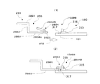
- the attachment portion 2BB formed integrally with the case portion 2 in the vicinity of the rear end portion (the left end side of FIG. 20 (1)) of the light irradiation device 210 is a body side portion of the case portion 2.
- 2BB1 the vertical portion 2BB2 extending substantially vertically inward in the radial direction from the main body side portion 2BB1, and the axial direction of the light irradiation device 210 from the radially inner end (the lower end of FIG. 20 (1)) of the vertical direction 2BB2.
- the horizontal portion 2BB3 extends horizontally in the horizontal direction of 20).
- a support shaft 2BB4A and a square annular locking portion 2BB4B are provided, and the locking member 2BB4 is attached to the support shaft 2BB4A.
- One end is rotatably supported.
- the electrode 2BB5 is embedded in the radially inner surface (the lower surface in FIG. 20 (1)) near the front end of the horizontal portion 2BB3, and is necessary for the LED unit 1 of the light irradiation device 210 to emit light via the electrode 2BB5. Power is supplied.
- a plurality of mounting portions 2BB (for example, four locations) are provided at substantially equal intervals in the circumferential direction. However, at least one electrode 2B5 may be provided.
- an attachment portion 102BB is provided on the beauty instrument 180 side.
- a protrusion 315 is provided on the outer peripheral side (upper side in FIG. 20 (1)) near the front end (left end in FIG. 20 (1)) of the main body case 101, and the outer peripheral side of the protrusion 315 (upper side in FIG. 20 (1)). Is provided with a locking receiving portion 316 corresponding to the locking member 2BB4 on the light irradiation device 210 side.
- An electrode 317 is embedded on the outer peripheral side (upper side in FIG. 20 (1)) of the protrusion 315 on the light irradiation device 210 side (left side in FIG. 20), and the electrode 317 is placed on the beauty instrument 180 side via a circuit (not shown). Power is supplied from the power source.
- the radial dimension (thickness dimension) of the protrusion 315 provided in the main body case 101 is approximately equal to the radial dimension (thickness dimension) of the horizontal portion 2BB3 of the mounting portion 2B on the light irradiation device 210 side.
- the protrusion 315 functions as a stopper for the horizontal portion 2BB3 on the light irradiation device 210 side.
- the attachment part 102BB on the beauty instrument 180 side is provided at a plurality of positions (for example, four places) at substantially equal intervals in the circumferential direction at positions corresponding to the attachment part 2BB on the light irradiation device 210 side.
- the position of the mounting portion 2BB on the light irradiation device 210 side is aligned with the mounting portion 102BB on the beauty tool 180 side. Then, the mounting portion 2BB is inserted into the mounting portion 102BB side (arrow AR3 side) until the tip of the horizontal portion 2BB3 (the right end in FIG. 20 (1)) comes into contact with the protruding portion 315. Then, if the rectangular annular locking portion 2BB4B of the locking member 2BB4 of the horizontal portion 2BB3 is rotated clockwise in FIG. 20 (1) to engage the locking portion 2BB4B with the locking receiving portion 316, the light Irradiation device 210 is attached to beauty tool 180 (state shown in FIG.
- FIG. 20 (2) In order to remove the light irradiation device 210 from the beauty tool 180, in FIG. 20 (2), the locking portion 2BB4B is rotated counterclockwise in FIG. 20 (2), and the locking portion 2BB4B is locked. The engagement may be released from the portion 316.
- the light irradiation device 210 By engaging the mounting portions 2BB on the light irradiation device 210 side and the mounting portions on the beauty device 180 side at a plurality of locations (for example, four locations), the light irradiation device 210 is securely attached to the beauty device 180, and FIG. 2).
- the electrode 2BB5 of the light irradiation device 210 and the electrode 317 on the beauty tool 180 side are in contact, and the electrode 2BB5 and the electrode 317 are in a conductive state. Become.
- the power necessary for the LED unit 1 of the light irradiation device 210 to emit light is supplied from the power supply on the beauty device 180 side via the electrode 317 on the beauty device 180 side and the electrode 2BB5 of the light irradiation device 210. I can do it.
- the plurality of LEDs 1 ⁇ / b> A of the LED unit 1 are arranged in a circular shape at substantially equal intervals on a mounting substrate 1 ⁇ / b> C (not shown).
- Each LED 1A irradiates light in a direction inclined inward in the radial direction with respect to the axial direction of the light irradiation device 210 (left and right direction in FIGS. 16 and 22) at the position where each LED 1A is disposed.
- the light emitted from the individual LEDs 1A travels in a direction inclined radially inward with respect to the axial direction. 21 and 22, the traveling direction of the light emitted from the LED is indicated by an arrow L.
- the light emitted from the individual LEDs 1A is adjusted by adjusting the installation direction. , It can be made to advance in a direction inclined radially inward with respect to the axial direction. Or what is necessary is just to make the mounting board
- the mounting substrate 1CA shown in FIG. 23 is not an annular flat plate, and the annular LED mounting surface 1CAS is formed so that the mounting surface 1CAS of the LED 1A becomes thicker from the radially inner side toward the radially outer side. Inclined.
- the through hole 1CAH is a through hole.
- a various aspect is employable.
- the light emitted from the plurality of LEDs 1A provided in the light irradiation device 210 is irradiated to the scalp of the user. Therefore, the cell activity in the user's scalp is improved by the wavelength of the light emitted from the LED 1A, and the skin tissue and the growth of fibroblasts, synthesis of growth factors, production of collagen, increase in angiogenesis, etc. It has a positive effect on hair and can improve the condition of the scalp.
- the light irradiation apparatus 210 is comprised so that attachment or detachment to the beauty instruments 180 is possible, it can be easily applied to the existing beauty instruments 180. In other words, it is possible to apply the second embodiment without significantly modifying the existing beauty instrument 180.
- the plurality of LEDs 1A provided in the light irradiation device 210 are arranged in a circle, and the light emitted from the individual LEDs 1A is directed toward the circular radially inner region. Since LED1A is arrange
- the electrode on the light irradiation device 210 and the electrode on the beauty tool 180 come into contact with each other. Since power can be supplied to the light irradiation device 210 side, the power necessary for the LED 1A to irradiate light by the power supply on the beauty tool 180 side can be obtained without providing a new power supply on the light irradiation device 210 side. Supplied.
- the light irradiation device 220 according to the third embodiment is attached to the air outlet 101B side (the left side in FIG. 24) of the beauty tool 180.
- the light irradiation device 220 is different from the light irradiation device 210 in the second embodiment in that it has a spray device 215 that can be attached to and detached from the upper surface of the case portion 222.
- the upper space in the case portion 222 of the light irradiation device 220 is larger than the lower space and the side space in order to secure the space for the spraying portion 15B of the spraying device 215 and the space for spraying. It is configured.
- the shape of the light irradiation device 220 viewed from the left side of FIG. 24 is not a perfect circle, but is an ellipse that is long (vertically long) vertically.
- the other structure in the light irradiation apparatus 220 of FIG. 24 is the same as that of the light irradiation apparatus 210 in 2nd Embodiment.
- the spraying device 215 has a function of spraying a so-called “hairdressing” liquid such as a hairdressing agent in a mist form in the case portion 222.
- the spray device 215 includes a liquid storage unit 15A installed on the upper surface side of the case unit 222, a spray unit 15B installed in the case unit 222, and a communication pipe 15C that communicates the liquid storage unit 15A and the spray unit 15B.
- the communication pipe 15 ⁇ / b> C penetrates the upper surface of the case portion 222 of the light irradiation device 220.
- the spray device 215 is fixed to the upper surface of the case portion 222 by a fastening member 15D.
- the aspect which fixes the spraying device 215 to the upper surface of the case part 222 may use members other than fastening member 15D.
- a part of the electric power supplied from the power supply on the beauty instrument 180 side to the light irradiation device 220 is supplied to the spraying device 215 via a circuit (not shown).
- the hot air or the cold air is, as shown by the arrow F6, the air passage in the beauty tool 180, The air passes through the air passage in the light irradiation device 220 and is blown from the outlet of the light irradiation device 220 toward the user's hair (cosmetic object).
- the operation switch unit 318 when the operation switch unit 318 is operated to activate the spraying device 215, the hair-styling liquid is sprayed in the form of a mist from the spraying unit 15B of the spraying device 215 onto the air passage of the light irradiation device 220 (arrow F7). ).
- the mist-like hair liquid sprayed from the spraying device 215 is entrained by the warm air or cold air blown from the beauty device 180 and efficiently reaches the hair of the user who is the beauty target. Alternatively, even when there is no air blow from the beauty tool 180, the hair liquid stored in the spray device 215 can reach the user's hair by the spray force of the spray device 215. If the LED 1A of the light irradiation device 220 is turned on in addition to spraying the hairdressing liquid from the spray device 215, the light of a specific wavelength is irradiated from the LED 1A to the user's scalp, and the state of the user's scalp It is also done to improve.
- the spraying device 215 can be attached to and detached from the light irradiation device 220, and the spraying device 215 has a spraying section that sprays the liquid for beautifying hair in a mist form.
- the effect of improving the condition of the hair can be obtained by spraying a liquid for beautifying hair.
- the sprayed hair liquid is entrained in the warm air or cold air blown from the hairdressing device 180, and is a beauty object. Is efficiently supplied to the user's hair.
- Other configurations and operational effects in the third embodiment of FIG. 24 are the same as those of the second embodiment described with reference to FIGS.
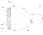
- the beauty tool 180 is a hair dryer, but in the fourth embodiment of FIGS. 25 and 26, the beauty tool 280 is a beauty roller (facial device).
- the beauty device 280 which is a beauty roller, has a pair of upper and lower rollers 202 in the head portion 201, and rotates the roller 202 by a power source (not shown) to massage the skin of the face to promote blood flow. It has the effect of activating metabolism.
- the operation switch unit 204 is an operation switch unit. Beauty equipment 280
- the light irradiation device 330 is the same as the light irradiation device 210 in the second embodiment, but is attached to the beauty device 280 instead of the beauty device 180.
- Various dimensions such as the length in the side surface direction, the number of LEDs 1A, and the like are different.
- the roller 202 of the beauty device 280 needs to protrude from the LED portion 31 at the tip of the light irradiation device 330 (see FIG. 26).
- the direction (left and right direction in FIGS. 25 and 26) length L12 is set smaller than in the embodiments of FIGS.
- the attachment mechanism 32B for attaching the light irradiation device 330 to the beauty tool 280 side and the power supply mechanism from the beauty tool 280 side are the same as those in the embodiments of FIGS.
- FIG. 26 which shows the state which attached the light irradiation apparatus 330 to the beauty tool 280
- the roller 202 protrudes in the light irradiation direction (left direction of FIG. 26) rather than the light irradiation apparatus 330.
- FIG. 26 In order to exert the facial effect of the beauty device 280, the roller 202 needs to contact the user's face, but the roller 202 does not protrude in the light irradiation direction (left direction in FIG. 26) from the light irradiation device 330. This is because the light irradiation device 330 comes into contact with the user's face, and the roller 202 cannot contact the user's face.
- the light irradiation device 330 When using the beauty tool 280, the light irradiation device 330 is operated by operating the operation switch unit 204, and light of a desired wavelength and intensity is irradiated from the LED to activate the user's skin. I can plan. As shown in FIG. 26, when the light irradiation device 330 is used by being attached to the beauty tool 280, the beauty tool 280 is operated to perform the treatment of the face that is a beauty object, and then the light irradiation device 330 receives light from the light irradiation device 330. Can be used to activate the scalp.
- the LED light irradiated from the light irradiation device 330 is applied to the user's scalp. Irradiation improves cell activity in the user's scalp and has a positive effect on the skin tissue and hair through fibroblast proliferation, growth factor synthesis, collagen production, increased angiogenesis, etc. The state of can be improved. Therefore, the beauty effect can be improved synergistically.
- Other configurations and operational effects in the fourth embodiment shown in FIGS. 25 and 26 are the same as those in the second embodiment described with reference to FIGS.
- a light irradiation apparatus comprising a plurality of light emitting diodes and capable of being attached to and detached from a beauty tool.
- the plurality of LEDs are arranged in a closed shape constituted by a curve, and light emitted from each LED proceeds in a direction inclined toward an inner region of the shape.
- Light irradiation device (Claim 3) It has a spraying device which can be attached and detached, and this spraying device has a liquid storing part and a spraying part which injects the liquid stored in this liquid storing part in the shape of a mist.
- the light irradiation apparatus according to claim 1.
- the object of the present invention has been made in view of such problems, and in a light irradiation apparatus that irradiates light to the scalp and the like, it is possible to increase the amount of light reaching the scalp and the like while suppressing the influence of light entering the eyes. It is in providing the technique of a light irradiation apparatus.
Landscapes
- Health & Medical Sciences (AREA)
- Biomedical Technology (AREA)
- Life Sciences & Earth Sciences (AREA)
- Engineering & Computer Science (AREA)
- Nuclear Medicine, Radiotherapy & Molecular Imaging (AREA)
- Pathology (AREA)
- Biophysics (AREA)
- Radiology & Medical Imaging (AREA)
- Animal Behavior & Ethology (AREA)
- General Health & Medical Sciences (AREA)
- Public Health (AREA)
- Veterinary Medicine (AREA)
- Radiation-Therapy Devices (AREA)
Abstract
Description
次に、図4から6を参照して、カバー部材18について説明する。図4はカバー部材18の正面図、図5はその側面図、図6はその背面図である。
複数の発光素子20が被照射部70である頭皮や頭髪に直接接触すると、複数の発光素子20に皮脂などの異物が付着して複数の発光素子20の表面が曇ることがある。複数の発光素子20の表面が曇ると出力される光量が減少することが考えられる。このため、複数の発光素子20は被照射部70に直接接触しないことが望ましい。そこで、光照射装置100では、発光部10には光束28が透過するカバー部材18が交換可能に設けられている。この場合、カバー部材18に異物が付着した場合は外して洗浄することができる。カバー部材18には容易に取り付けと取り外しができる係合部が設けられてもよい。
カバー部材の前側の表面が平坦である場合には、カバー部材が頭髪を押さえて密集させるから、光束は頭髪に当たる割合が増えて頭皮に届く割合が小さくなることが考えられる。そこで、光照射装置100では、カバー部材18は第1方向P側に突出する複数の突出部19を有している。この場合、突出部19は頭髪の間に分け入り、突出部19の先端が頭皮に接近するから、光束28が効率的に頭皮に届くようになる。また、突出部19の先端が頭皮に当たることで、頭皮に適度な刺激を加え、血流を促進することが可能になる。
次に、図8、9を参照して、フード部材15について説明する。図8はフード部材15の正面図、図9はその側面図である。
光束28の一部が外側に漏れると、その漏れた光が目に入ることが考えられる。そこで、光照射装置100では、発光部10に、第1方向P側で光束28を囲むフード部材15が設けられている。フード部材15を設けたことにより外側に漏れる光量を減らすことができる。なお、フード部材15を被照射部70に接触可能に設けることで、外側に漏れる光量をさらに減らすことができる。フード部材15はカバー部材18の突出部19より前方に突出するように設けられてもよい。フード部材15には、カバー部材18の後退領域18aに対応する後退領域15aと、前進領域18bに対応する前進領域15bと、が設けられる。前進領域15bは後退領域15aより第1方向Pで前方に前進している。
使用者の利便の観点から、光照射装置は広い範囲に光束を照射できることが望ましい。そこで、光照射装置100では、図10に示すように、発光部10は、複数の発光素子20を含んでいる。複数の発光素子20としては例えばLED(light emitting diode)またはLD(diode laser)を用いることができる。光照射装置100では、複数の発光素子20が空気流42の周囲を囲むように配置される。複数の発光素子20は、空気流42を囲むように円形状、オーバル形状または多角形状に配置されてもよい。
光照射装置は、例えば頭部を複数の被照射部に分けて、それぞれの被照射部毎に所定の時間ずつ使用されることがある。使い勝手の観点から、それぞれの被照射部への使用時間は好ましくは3秒から30秒の範囲、より好ましくは5秒から20秒の範囲にすることができる。それぞれの被照射部への使用時間は、光照射装置の光束が大きい場合は短く、小さい場合は長くなる。このような使用時間について合図が出力されると使用者に便利である。そこで、光照射装置100では、図3に示すように、所定のタイミングで使用者が知覚できる合図を出力するように構成される合図出力部34を備えている。一例として、合図出力部は、設定された時間(例えば10秒)毎に合図であるビープ音34eを出力するようにしてもよい。使用者は合図のタイミングで使用位置を切り替えて使用することができる。合図としては使用者が知覚できるものであれば特に制限はない。なお、理解を容易にするため、図1、2では合図出力部34の記載を省略している。
送風部40は、図3に示すように、筐体110と、グリップ部108と、吸入口116と、送出口114と、インペラ43と、モータ41と、ヒータ44と、制御部50と、スイッチ部52と、配線通路部118と、第1接点部36と、電源部124と、第1係合部82と、を含む。
発光部10は、図3に示すように、ハウジング30と、通気口86と、カバー部材18と、フード部材15と、基板13と、電子部品14と、複数の発光素子20と、第2接点部38と、第2係合部84と、を含む。
電流制限部32は、発光部10が被照射部70から所定の距離以上に離れると、発光部10に供給する電流を遮断または減らすように構成される。電流制限部32は、センサ部32aを含み、センサ部32aの状態に応じて発光部10に供給する電流を遮断または減らすように構成される。センサ部32aには、機械的な接触に対応して出力状態が変化するリミットスイッチや、光や音波を利用した距離センサを採用することができる。実施の形態の光照射装置100では、図3に示すよう、センサ部32aがハウジング30の外周部に取り付けられている。センサ部32aは、前方側に前向きに突き出ている先端部32eを有しており、先端部32eが被照射部70に接して押し込まれるとオンになるリミットスイッチ32bを内蔵している。図13に示すよう、リミットスイッチ32bは発光部10に直列に接続されており、非使用時はオフで、先端部32eが被照射部70に接するとオンになり発光部10に通電する。先端部32eの位置を調整することで、通電と非通電の切り替え距離を所望の距離に設定することができる。
合図出力部34は、所定のタイミングで、音、振動および光の少なくとも何れかを用いた合図を出力するように構成される。合図出力部34は、発光部10または送風部40に設けられる。光照射装置100では、図3に示すように、合図出力部34はハウジング30の外周部に設けられている。実施の形態の光照射装置100では、合図出力部34は、発光部10への電流の供給開始から所定の時間経過したタイミングで合図を出力するように構成される。合図出力部34は、図13のブロック配線図に示すように、発光部10への通電開始後に設定した設定時間を経過すると出力状態がオフからオンに変化するタイマー手段34aと、タイマー手段34aの出力状態がオンであるときにビープ音34eを発生させるブザー手段34bとを含んでいる。タイマー手段34aは発光部10が通電状態になることでアクティブになり、時間のカウントを開始する。タイマー手段34aは所定の時間カウントが経過するとブザー手段34bに通電してビープ音34eを発生させる。発光部10が非通電状態になるとタイマー手段34aはリセットされ、ブザー手段34bは休止する。さらに、発光部10が通電状態になると、タイマー手段34aはアクティブになり、合図出力部34は上記の動作を繰り返す。
(1)第1の使用形態
第1の使用形態は、送風部40は非稼働状態として、発光部10の発光機能のみを使用する。このモードを第1モードと表記する。まず、スイッチ部52を操作して、光照射装置100を第1モードに切り替える。この状態では、電流制限部32が働いており、発光部10は非発光状態にある。発光部10を頭部に接近させて先端部32eが被照射部70に接すると、発光部10は通電され発光を開始して被照射部70に光束28を照射する。これと同時にタイマー手段34aが起動し、例えば設定した10秒が経過するとブザー手段34bからビープ音34eを発生させる。使用者は、ビープ音34eに応じて、発光部10を一旦頭部から離す。この状態で発光およびビープ音34eは停止する。使用者が、発光部10を頭部の別位置の被照射部70に接近させて置くことで先端部32eが被照射部70に接すると、上記と同様の動作を繰り返す。これらの動作を繰り返すことで頭部の所望の範囲に光束28を受けることができる。
第2の使用形態は、送風部40を非加熱の涼風を送風する状態にして、発光部10の発光機能と共に使用する。このモードを第2モードと表記する。まず、スイッチ部52を操作して、光照射装置100を第2モードに切り替える。この状態では、送風部40が送出した非加熱の空気流42が発光部10の中孔部16を通過して出口部16bから吐き出されている。発光部10を頭部に接近させると、頭部には空気流42が当たる。さらに、発光部10を頭部に接近させて先端部32eが被照射部70に接すると、発光部10は通電され発光を開始して被照射部70に光束28を照射する。つまり、この状態では被照射部70には非加熱の空気流42と光束28とが同時に当たる。第1の使用モードと同様に、合図出力部34が稼働することで、所定のタイミングでビープ音34eが発生する。使用者は、ビープ音34eに応じて、使用者が、発光部10を頭部の別位置の被照射部70に置くことで上記と同様の動作を繰り返す。これらの動作を繰り返すことで、使用者は、頭部の所望の範囲に非加熱の空気流42と光束28とを同時に受けることができる。
第3の使用形態は、送風部40を加温した温風を送風する状態にして、発光部10の発光機能と共に使用する。このモードを第3モードと表記する。まず、スイッチ部52を操作して、光照射装置100を第3モードに切り替える。この状態では、送風部40が送出した加温した空気流42が発光部10の中孔部16を通過して出口部16bから吐き出されている。以下の動作は第2の使用形態と同様であり、この動作を繰り返すことで、頭部の所望の範囲に加温した空気流42と光束28とを同時に受けることができる。
第4の使用形態は、発光部10は非稼働状態として、送風部40の送風機能のみを使用する。この場合、発光部10は送風部40から取り外した状態で使用してもよいし、取り付けた状態で使用してもよい。以下は、取り付けた状態で使用する例を説明する。このモードを第4モードと表記する。まず、スイッチ部52を操作して、光照射装置100を第4モードに切り替える。この状態では、送風部40が送出した非加熱または加温した空気流42が発光部10の中孔部16を通過して出口部16bから吐き出される。第4の使用形態によると、使用者は、頭部の所望の範囲に非加熱または加温した空気流42を受けることができる。なお、第4の使用形態では合図出力部34は使用してもよいし、使用しなくてもよい。
光照射装置100では、赤色光を出力するLEDを使用する例について説明したが、これに限られない。例えば、緑色や青色の光を出力するLEDを使用してもよく、異なった色の光を出力するLEDを組み合わせて使用してもよい。
光照射装置100では、発光素子としてLEDまたはLDを使用する例について説明したが、これに限られない。例えば、有機EL素子など他の種類の発光素子を使用してもよい。
本発明の光照射装置には、マイナスイオンを含む空気を送出する手段や、水や美容液などの液体を微粒化したミストを送出する手段などを備えてもよい。
ここで、前記LEDは、例えば、620~670nm(赤色)、450~480nm(青色)、560~600nm(黄色)、500~530nm(緑色)の何れか或いは全ての波長の光を照射するのが好ましい。
本明細書において、美容器具という文言は、髪型を整えるためのヘアドライヤと、顔の肌を活性化して所謂「美肌」にするための美顔用器具(例えば、美顔用ローラーその他の各種美顔用機器)を包含する意味で用いられている。
美容器具280は美顔用器具(例えば、美顔用ローラーその他の各種美顔用機器)であるのが好ましい。
図17において、美容器具180は、温風/冷風の吹出口101Bの近傍で、図14~図16を参照して説明した光照射装置210を取り付けている。図17で示す美容器具180は、光照射装置210の取り付け構造および光照射装置210への電力供給機構を具備する特徴を有する。
水平部2BA3の前端側(図19(1)では右側)の半径方向内方(図19(1)では下方)の面(内周面)には雌ネジ2BA4が形成されている。
そして、光照射装置210は美容器具180に取り付け及び取り外し可能に構成されているので、既存の美容器具180に対して、容易に適用することが可能である。換言すれば、既存の美容器具180を大幅に改造すること無く、第2実施形態を適用することが可能である。
図24において、美容器具180の吹出口101B側(図24の左側)に、第3実施形態に係る光照射装置220が取り付けられている。光照射装置220は、ケース部222の上面に取り付け及び取り外し可能な噴霧装置215を有する点で、第2実施形態における光照射装置210とは異なっている。そして、光照射装置220のケース部222内の上方空間は、噴霧装置215の噴霧部15Bの設置と、噴霧のための空間を確保するため、下方の空間や側方の空間に比較して大きく構成されている。換言すれば、図24の左側から視た光照射装置220の形状は、真円形ではなく、上下に長い(縦長の)楕円形となっている。図24の光照射装置220におけるその他の構造は、第2実施形態における光照射装置210と同様である。
図14~図24の第2実施形態及び第3実施形態では美容器具180はヘアドライヤであるが、図25、図26の第4実施形態では、美容器具280は美顔ローラー(美顔器)である。美顔ローラーである美容器具280は、ヘッド部201に上下一対のローラー202を有し、図示しない電源によりローラー202を回転させて顔の皮膚をマッサージすることで血流を促進し、顔の皮膚の新陳代謝を活発にする効果がある。図25、図26において、操作スイッチ部204は操作スイッチ部である。
美容器具280
(請求項1)複数の発光ダイオードを備え且つ美容器具に取り付け及び取り外し可能であることを特徴とする光照射装置。
(請求項2)前記複数のLEDは曲線で構成される閉じた形状に配置されており、個々のLEDから照射される光が前記形状の内側領域に向かって傾斜する方向に進行する請求項1の光照射装置。
(請求項3)取り付け及び取り外し可能な噴霧装置を有しており、該噴霧装置は、液体貯蔵部と、該液体貯蔵部に貯蔵された液体を霧状に噴射する噴霧部を有している請求項1、2の何れかの光照射装置。
16 中孔部、 16b 出口部、 18 カバー部材、
18a 後退領域、 18b 前進領域、 19 突出部、
19b 凹部、 20 発光素子、 21 発光素子、 22 発光素子、
28 光束、 30 ハウジング、 32 電流制限部、
32b リミットスイッチ、 34 合図出力部、 36 第1接点部、
38 第2接点部、 40 送風部、 41 モータ、 42 空気流、
43 インペラ、 44 ヒータ、 50 制御部、 52 スイッチ部、
70 被照射部、 82 第1係合部、 84 第2係合部、
86 通気口、 100 光照射装置、 108 グリップ部、
110 筐体、 114 送出口、 116 吸入口、
118 配線通路部、 124 電源部、 126 電気ケーブル、
128 電気ケーブル。
Claims (15)
- 第1方向に流れる空気流を送出するための送風部と、
被照射部である頭皮または頭髪を照らすための光束を出力する発光部と、
を備え、
前記発光部は前記送風部の第1方向側に設けられることを特徴とする光照射装置。 - 前記送風部は前記被照射部に向けて前記空気流を送出するように構成されることを特徴とする請求項1に記載の光照射装置。
- 前記発光部には前記光束が透過するカバー部材が交換可能に設けられることを特徴とする請求項1または2に記載の光照射装置。
- 前記カバー部材は第1方向側に突出する複数の突出部を有することを特徴とする請求項3に記載の光照射装置。
- 前記カバー部材は、第1方向で前記送風部側に後退している後退領域と、前記後退領域より第1方向で前進している前進領域と、を含むことを特徴とする請求項3または4に記載の光照射装置。
- 前記発光部には、第1方向側で光束を囲むフード部材が設けられることを特徴とする請求項1から5のいずれかに記載の光照射装置。
- 前記発光部は、複数の発光素子を含むことを特徴とする請求項1から6のいずれかに記載の光照射装置。
- 前記複数の発光素子は、第1方向において、第1方向で前記送風部側に後退している発光素子と、前記後退している発光素子より第1方向で前進している発光素子と、を含むことを特徴とする請求項7に記載の光照射装置。
- 前記複数の発光素子の少なくとも一部は、第1方向に対して傾斜して設けられることを特徴とする請求項7または8に記載の光照射装置。
- 前記複数の発光素子の少なくとも一部は前記空気流が通過する領域に配置されることを特徴とする請求項7から9のいずれかに記載の光照射装置。
- 前記発光部は、前記複数の発光素子のいずれかに電気的に接続される電子部品の少なくとも一部が前記空気流が通過する範囲に配置されることを特徴とする請求項7から10のいずれかに記載の光照射装置。
- 前記発光部が前記被照射部から所定の距離以上に離れると、前記発光部に供給する電流を遮断または減らすように構成される電流制限部をさらに備えることを特徴とする請求項1から11のいずれかに記載の光照射装置。
- 所定のタイミングで、使用者が知覚できる合図を出力するように構成される合図出力部をさらに備えることを特徴とする請求項1から12のいずれかに記載の光照射装置。
- 前記合図出力部は、前記発光部への電流の供給開始から所定の時間経過したタイミングで音、振動および光の少なくとも何れかを用いた合図を出力するように構成されることを特徴とする請求項13に記載の光照射装置。
- 前記発光部は、前記送風部に対して取り付けおよび取り外し可能に設けられ、
前記送風部は、前記発光部に電流を供給するための第1接点部を有し、
前記発光部は、前記送風部に装着された状態にて前記第1接点部に電気的に接続される第2接点部を有することを特徴とする請求項1から14のいずれかに記載の光照射装置。
Priority Applications (6)
| Application Number | Priority Date | Filing Date | Title |
|---|---|---|---|
| CN201680023969.8A CN107529865A (zh) | 2015-04-27 | 2016-04-20 | 光照射装置 |
| KR1020177029349A KR102112121B1 (ko) | 2015-04-27 | 2016-04-20 | 광조사 장치 |
| CA2983573A CA2983573C (en) | 2015-04-27 | 2016-04-20 | Light irradiation device |
| EP16786379.4A EP3289912A4 (en) | 2015-04-27 | 2016-04-20 | Light irradiation device |
| KR1020207013524A KR20200055158A (ko) | 2015-04-27 | 2016-04-20 | 광조사 장치 |
| US15/726,004 US20180036553A1 (en) | 2015-04-27 | 2017-10-05 | Light irradiation device |
Applications Claiming Priority (4)
| Application Number | Priority Date | Filing Date | Title |
|---|---|---|---|
| JP2015089953A JP2018102326A (ja) | 2015-04-27 | 2015-04-27 | 光照射装置 |
| JP2015-089953 | 2015-04-27 | ||
| JP2015252512 | 2015-12-24 | ||
| JP2015-252512 | 2015-12-24 |
Related Child Applications (1)
| Application Number | Title | Priority Date | Filing Date |
|---|---|---|---|
| US15/726,004 Continuation US20180036553A1 (en) | 2015-04-27 | 2017-10-05 | Light irradiation device |
Publications (1)
| Publication Number | Publication Date |
|---|---|
| WO2016175102A1 true WO2016175102A1 (ja) | 2016-11-03 |
Family
ID=57199182
Family Applications (1)
| Application Number | Title | Priority Date | Filing Date |
|---|---|---|---|
| PCT/JP2016/062531 Ceased WO2016175102A1 (ja) | 2015-04-27 | 2016-04-20 | 光照射装置 |
Country Status (6)
| Country | Link |
|---|---|
| US (1) | US20180036553A1 (ja) |
| EP (1) | EP3289912A4 (ja) |
| KR (2) | KR102112121B1 (ja) |
| CN (1) | CN107529865A (ja) |
| CA (1) | CA2983573C (ja) |
| WO (1) | WO2016175102A1 (ja) |
Cited By (3)
| Publication number | Priority date | Publication date | Assignee | Title |
|---|---|---|---|---|
| WO2019054131A1 (ja) * | 2017-09-14 | 2019-03-21 | シャープ株式会社 | ヘアドライヤ |
| JP2019051017A (ja) * | 2017-09-14 | 2019-04-04 | シャープ株式会社 | ヘアドライヤ |
| WO2020026510A1 (ja) * | 2018-07-31 | 2020-02-06 | メトラス株式会社 | 光照射装置及び光照射装置の製造方法 |
Families Citing this family (46)
| Publication number | Priority date | Publication date | Assignee | Title |
|---|---|---|---|---|
| KR101658622B1 (ko) * | 2015-02-24 | 2016-09-22 | 유닉스전자주식회사 | 바람 진동 장치 및 이를 포함하는 헤어드라이어 |
| US10299560B1 (en) * | 2017-11-10 | 2019-05-28 | Follicle, LLC | Battery operated hair dryer |
| CN108261127B (zh) * | 2018-01-31 | 2021-12-14 | 深圳市米谷智能有限公司 | 美肤仪的控制方法及系统 |
| US11268758B2 (en) * | 2018-04-23 | 2022-03-08 | Lillian Sanfilippo | Dryer |
| EP3598919A1 (en) | 2018-07-25 | 2020-01-29 | Koninklijke Philips N.V. | Hair dryer attachment |
| KR102758296B1 (ko) * | 2018-12-13 | 2025-01-23 | 엘지전자 주식회사 | 펫 케어 장치 |
| US10478635B1 (en) | 2018-10-22 | 2019-11-19 | Joovv, Inc. | Photobiomodulation therapy systems and methods |
| US11458328B2 (en) | 2018-10-22 | 2022-10-04 | Joovv, Inc. | Photobiomodulation therapy device accessories |
| US10525277B1 (en) | 2019-01-08 | 2020-01-07 | Laluer Llc | Skin treatment device |
| KR102235266B1 (ko) * | 2019-02-08 | 2021-04-06 | 한양대학교 에리카산학협력단 | 치료용 헤어 드라이어 |
| TWM586551U (zh) * | 2019-05-03 | 2019-11-21 | 迪伸電子股份有限公司 | 具有雷射功能的梳子 |
| TWI718591B (zh) * | 2019-07-18 | 2021-02-11 | 徐士凌 | 吹風機噴霧結構 |
| JP2021132691A (ja) * | 2020-02-21 | 2021-09-13 | パナソニックIpマネジメント株式会社 | 美容成分噴霧装置 |
| JP7411896B2 (ja) * | 2020-02-21 | 2024-01-12 | パナソニックIpマネジメント株式会社 | 美容成分噴霧装置 |
| JP7291893B2 (ja) * | 2020-02-21 | 2023-06-16 | パナソニックIpマネジメント株式会社 | 美容成分噴霧装置 |
| USD913509S1 (en) * | 2020-03-06 | 2021-03-16 | Cryoconcepts Lp | Applicator device for dispensing carbon dioxide enhanced topical substances |
| KR102364689B1 (ko) | 2020-04-10 | 2022-02-18 | 엘지전자 주식회사 | 디퓨저 및 이를 포함하는 헤어드라이어 |
| KR102364691B1 (ko) | 2020-04-10 | 2022-02-18 | 엘지전자 주식회사 | 디퓨저 및 이를 포함하는 헤어드라이어 |
| KR102366462B1 (ko) * | 2020-04-10 | 2022-02-23 | 엘지전자 주식회사 | 디퓨저 및 이를 포함하는 헤어드라이어 |
| KR102364692B1 (ko) * | 2020-04-10 | 2022-02-18 | 엘지전자 주식회사 | 헤어드라이어 |
| KR102364690B1 (ko) | 2020-04-10 | 2022-02-18 | 엘지전자 주식회사 | 헤어드라이어 |
| KR102364681B1 (ko) | 2020-04-10 | 2022-02-18 | 엘지전자 주식회사 | 디퓨저 및 이를 포함하는 헤어드라이어 |
| KR102364682B1 (ko) | 2020-04-10 | 2022-02-18 | 엘지전자 주식회사 | 디퓨저 및 이를 포함하는 헤어드라이어 |
| KR102366461B1 (ko) | 2020-04-10 | 2022-02-23 | 엘지전자 주식회사 | 디퓨저 및 이를 포함하는 헤어드라이어 |
| WO2021211238A1 (en) * | 2020-04-13 | 2021-10-21 | Johann Verheem | Light treatment device |
| CN216644559U (zh) | 2020-05-09 | 2022-05-31 | 深圳汝原科技有限公司 | 干燥装置以及供电模组 |
| WO2021226749A1 (en) * | 2020-05-09 | 2021-11-18 | Sz Zuvi Technology Co., Ltd. | Apparatuses and methods for drying an object |
| GB2610538B (en) | 2020-05-09 | 2024-11-06 | Sz Zuvi Tech Co Ltd | Apparatus and methods for drying an object |
| US11464313B2 (en) | 2020-05-09 | 2022-10-11 | Sz Zuvi Technology Co., Ltd. | Apparatuses and methods for drying an object |
| JP7128973B2 (ja) | 2020-05-09 | 2022-08-31 | 深▲せん▼汝原科技有限公司 | 物体を乾燥させる装置及び方法 |
| KR102226215B1 (ko) * | 2020-06-15 | 2021-03-12 | 김문정 | 에코헤어드라이어 |
| US11369180B1 (en) * | 2020-06-19 | 2022-06-28 | Tran Thien Khanh | Manicure ventilating and sanitizing lamp |
| CN111700788B (zh) * | 2020-06-28 | 2022-11-15 | 深圳市美高途科技有限公司 | 一种便携式护肤美容按摩仪器 |
| USD963873S1 (en) | 2020-09-21 | 2022-09-13 | Joovv, Inc. | Floor stand for a photobiomodulation therapy device |
| USD1004789S1 (en) | 2020-09-21 | 2023-11-14 | Joovv, Inc. | Photobiomodulation therapy device |
| USD1047162S1 (en) | 2020-09-21 | 2024-10-15 | Joovv, Inc. | Photobiomodulation therapy device |
| CN116390671A (zh) * | 2020-10-19 | 2023-07-04 | 夏普株式会社 | 美容设备 |
| KR102477154B1 (ko) * | 2020-12-08 | 2022-12-14 | 한국전자기술연구원 | 양방향 헤어 드라이어 |
| US12178301B2 (en) | 2020-12-14 | 2024-12-31 | Conair Llc | Glass hair styling iron with heat and light emitting source |
| KR20220098530A (ko) * | 2021-01-04 | 2022-07-12 | 엘지전자 주식회사 | 헤어 드라이어 |
| KR20220098531A (ko) * | 2021-01-04 | 2022-07-12 | 엘지전자 주식회사 | 헤어 드라이어 |
| WO2022199674A1 (zh) * | 2021-03-24 | 2022-09-29 | 深圳汝原科技有限公司 | 辐射源、干燥设备和反光座 |
| KR102336327B1 (ko) * | 2021-11-01 | 2021-12-08 | 이순 | 적외선 led를 이용한 헤어드라이어 |
| GB2612788B (en) * | 2021-11-10 | 2024-11-13 | Dyson Technology Ltd | A haircare appliance |
| USD1036769S1 (en) | 2022-08-09 | 2024-07-23 | Helen Of Troy Limited | Hair dryer |
| WO2025223155A1 (en) * | 2024-04-23 | 2025-10-30 | Shenzhen Ulike Smart Electronics Co., Ltd. | Beauty instrument |
Citations (8)
| Publication number | Priority date | Publication date | Assignee | Title |
|---|---|---|---|---|
| JPH07509641A (ja) * | 1993-03-02 | 1995-10-26 | ウエラ アクチェンゲゼルシャフト | 熱気流による対象物の処理方法およびこの方法を実施するためのハンド式器具 |
| JP2006025954A (ja) * | 2004-07-14 | 2006-02-02 | Ushio Inc | 赤外線治療器 |
| JP2008229176A (ja) * | 2007-03-22 | 2008-10-02 | Chiyoda Boshoku Kk | ヘアードライヤ |
| JP2010125134A (ja) * | 2008-11-28 | 2010-06-10 | Panasonic Electric Works Co Ltd | 送風装置 |
| JP2010131260A (ja) * | 2008-12-05 | 2010-06-17 | Panasonic Electric Works Co Ltd | 頭皮ケア装置 |
| US20110197466A1 (en) * | 2010-02-12 | 2011-08-18 | Farouk Systems, Inc. | Hair dryer |
| JP2013085948A (ja) * | 2011-10-13 | 2013-05-13 | Forward Electronics Co Ltd | 光治療器 |
| JP2013531535A (ja) * | 2010-06-30 | 2013-08-08 | イーエルシー マネージメント エルエルシー | 毛髪用製品及びブロードライヤとともに使用するための赤色発光デバイス |
Family Cites Families (23)
| Publication number | Priority date | Publication date | Assignee | Title |
|---|---|---|---|---|
| AU1380095A (en) * | 1994-01-21 | 1995-08-08 | Erik Larsen | Device for stimulating body cells by electromagnetic radiation |
| JP3662068B2 (ja) * | 1996-03-21 | 2005-06-22 | 飯村 惠次 | 光触媒装置および光触媒を用いたクリーニング装置 |
| US6063108A (en) * | 1997-01-06 | 2000-05-16 | Salansky; Norman | Method and apparatus for localized low energy photon therapy (LEPT) |
| US6077073A (en) * | 1998-09-15 | 2000-06-20 | Jacob; Gregory S. | Light emitting diode-array light apparatus |
| JP2001238968A (ja) * | 2000-03-01 | 2001-09-04 | Ya Man Ltd | レーザ光照射プローブ |
| US6629989B2 (en) * | 2001-10-18 | 2003-10-07 | Shimadzu Corporation | Phototherapy device for pressure pain point therapy and trigger point therapy |
| WO2004066899A2 (en) * | 2003-01-24 | 2004-08-12 | Engii (2001) Ltd. | System and method for face and body treatment |
| US7413567B2 (en) * | 2003-02-25 | 2008-08-19 | Spectragenics, Inc. | Optical sensor and method for identifying the presence of skin |
| KR100643516B1 (ko) * | 2003-05-06 | 2006-11-10 | 가부시키가이샤 모리타 세이사쿠쇼 | 의료용 광조사장치 |
| US7722600B2 (en) * | 2003-08-25 | 2010-05-25 | Cutera, Inc. | System and method for heating skin using light to provide tissue treatment |
| EP1833567A1 (en) * | 2004-11-09 | 2007-09-19 | Steven Gardner | Device and method of phototherapy for jaundiced infants |
| CA2618126A1 (en) * | 2005-08-08 | 2007-02-15 | Palomar Medical Technologies, Inc. | Eye-safe photocosmetic device |
| US20120010603A1 (en) * | 2005-08-12 | 2012-01-12 | Dermalucent, LLC | Tissue optical clearing devices for subsurface light-induced phase-change and method of use |
| JP4855914B2 (ja) | 2006-12-04 | 2012-01-18 | シーシーエス株式会社 | リング型照明装置 |
| JP2010518618A (ja) * | 2007-02-06 | 2010-05-27 | キム、テ ギュ | レーザーダイオード組立体及びこれを含む治療用シート |
| KR101396588B1 (ko) * | 2007-03-19 | 2014-05-20 | 서울반도체 주식회사 | 다양한 색온도를 갖는 발광 장치 |
| KR101155135B1 (ko) * | 2008-12-09 | 2012-06-11 | (주)비앤피테크 | 엘이디 탈부착형 헤어드라이기 |
| US20120316623A1 (en) * | 2010-02-12 | 2012-12-13 | Panasonic Corporation | Phototherapy device |
| JPWO2012060075A1 (ja) * | 2010-11-05 | 2014-05-12 | パナソニック株式会社 | 光治療装置 |
| EP2648651B1 (en) * | 2010-12-08 | 2016-11-23 | Biolux Research Limited | Apparatuses useful for regulating bone remodeling or tooth movement using light therapy and a functional appliance |
| JP2014128524A (ja) | 2012-12-30 | 2014-07-10 | Tsuyamote Beauty Co Ltd | ヘアドライヤー |
| KR101525123B1 (ko) * | 2014-08-29 | 2015-06-03 | 주식회사 비에스앤코 | 치아 미백 장치 |
| CN107249687B (zh) * | 2015-02-26 | 2019-05-21 | 夏普株式会社 | 光照射用基板 |
-
2016
- 2016-04-20 CN CN201680023969.8A patent/CN107529865A/zh active Pending
- 2016-04-20 CA CA2983573A patent/CA2983573C/en not_active Expired - Fee Related
- 2016-04-20 WO PCT/JP2016/062531 patent/WO2016175102A1/ja not_active Ceased
- 2016-04-20 KR KR1020177029349A patent/KR102112121B1/ko not_active Expired - Fee Related
- 2016-04-20 KR KR1020207013524A patent/KR20200055158A/ko not_active Ceased
- 2016-04-20 EP EP16786379.4A patent/EP3289912A4/en not_active Withdrawn
-
2017
- 2017-10-05 US US15/726,004 patent/US20180036553A1/en not_active Abandoned
Patent Citations (8)
| Publication number | Priority date | Publication date | Assignee | Title |
|---|---|---|---|---|
| JPH07509641A (ja) * | 1993-03-02 | 1995-10-26 | ウエラ アクチェンゲゼルシャフト | 熱気流による対象物の処理方法およびこの方法を実施するためのハンド式器具 |
| JP2006025954A (ja) * | 2004-07-14 | 2006-02-02 | Ushio Inc | 赤外線治療器 |
| JP2008229176A (ja) * | 2007-03-22 | 2008-10-02 | Chiyoda Boshoku Kk | ヘアードライヤ |
| JP2010125134A (ja) * | 2008-11-28 | 2010-06-10 | Panasonic Electric Works Co Ltd | 送風装置 |
| JP2010131260A (ja) * | 2008-12-05 | 2010-06-17 | Panasonic Electric Works Co Ltd | 頭皮ケア装置 |
| US20110197466A1 (en) * | 2010-02-12 | 2011-08-18 | Farouk Systems, Inc. | Hair dryer |
| JP2013531535A (ja) * | 2010-06-30 | 2013-08-08 | イーエルシー マネージメント エルエルシー | 毛髪用製品及びブロードライヤとともに使用するための赤色発光デバイス |
| JP2013085948A (ja) * | 2011-10-13 | 2013-05-13 | Forward Electronics Co Ltd | 光治療器 |
Non-Patent Citations (1)
| Title |
|---|
| See also references of EP3289912A4 * |
Cited By (10)
| Publication number | Priority date | Publication date | Assignee | Title |
|---|---|---|---|---|
| WO2019054131A1 (ja) * | 2017-09-14 | 2019-03-21 | シャープ株式会社 | ヘアドライヤ |
| JP2019051018A (ja) * | 2017-09-14 | 2019-04-04 | シャープ株式会社 | ヘアドライヤ |
| JP2019051017A (ja) * | 2017-09-14 | 2019-04-04 | シャープ株式会社 | ヘアドライヤ |
| CN111065294A (zh) * | 2017-09-14 | 2020-04-24 | 夏普株式会社 | 吹风机 |
| CN111065293A (zh) * | 2017-09-14 | 2020-04-24 | 夏普株式会社 | 吹风机 |
| CN111065294B (zh) * | 2017-09-14 | 2022-08-05 | 夏普株式会社 | 吹风机 |
| WO2020026510A1 (ja) * | 2018-07-31 | 2020-02-06 | メトラス株式会社 | 光照射装置及び光照射装置の製造方法 |
| JP2020022718A (ja) * | 2018-07-31 | 2020-02-13 | メトラス株式会社 | 光照射装置及び光照射装置の製造方法 |
| JP2020024898A (ja) * | 2018-07-31 | 2020-02-13 | メトラス株式会社 | 光照射装置及び光照射装置の製造方法 |
| JP2020036941A (ja) * | 2018-07-31 | 2020-03-12 | メトラス株式会社 | 光照射装置及び光照射装置の製造方法 |
Also Published As
| Publication number | Publication date |
|---|---|
| KR20170139520A (ko) | 2017-12-19 |
| CA2983573C (en) | 2020-03-24 |
| CA2983573A1 (en) | 2016-11-03 |
| KR102112121B1 (ko) | 2020-06-04 |
| KR20200055158A (ko) | 2020-05-20 |
| EP3289912A4 (en) | 2018-12-12 |
| US20180036553A1 (en) | 2018-02-08 |
| EP3289912A1 (en) | 2018-03-07 |
| CN107529865A (zh) | 2018-01-02 |
Similar Documents
| Publication | Publication Date | Title |
|---|---|---|
| KR102112121B1 (ko) | 광조사 장치 | |
| JP3207005U (ja) | ヘアケア装置 | |
| JP6488056B1 (ja) | 光照射装置及び光照射装置の製造方法 | |
| JP6703791B2 (ja) | ヘアドライヤ | |
| US20140135798A1 (en) | Light therapy skin device | |
| KR20140031858A (ko) | 피부 치료 장치 | |
| JP2007330690A (ja) | 美容装置 | |
| JP2019051017A5 (ja) | ||
| KR20110003355A (ko) | 모발 성장 장치 및 모발 성장 방법 | |
| EP1433499A1 (en) | Laser beam irradiation device | |
| KR20200097843A (ko) | 치료용 헤어 드라이어 | |
| KR102325386B1 (ko) | 피부 미용 기기 | |
| US11383092B2 (en) | Reactive gas application apparatus | |
| KR20120061495A (ko) | 수분공급기 | |
| KR200430522Y1 (ko) | 두피세척용 발광분사헤드 | |
| JP2018102326A (ja) | 光照射装置 | |
| KR20080017668A (ko) | 발광분사헤드 | |
| EP4497446A1 (en) | Light-based disinfecting device for a personal care device with drying function | |
| KR102602181B1 (ko) | 내비강 광조사 장치 | |
| US20230157752A1 (en) | Stimulation Device | |
| WO2025021670A2 (en) | Light-based disinfecting device for a personal care device with drying function | |
| KR20160130010A (ko) | 다파장 광원을 이용한 피부 복합 치료장치 | |
| US20190126059A1 (en) | Hair care device | |
| KR20120097203A (ko) | 피지선 질환 치료기 |
Legal Events
| Date | Code | Title | Description |
|---|---|---|---|
| 121 | Ep: the epo has been informed by wipo that ep was designated in this application |
Ref document number: 16786379 Country of ref document: EP Kind code of ref document: A1 |
|
| ENP | Entry into the national phase |
Ref document number: 20177029349 Country of ref document: KR Kind code of ref document: A |
|
| REEP | Request for entry into the european phase |
Ref document number: 2016786379 Country of ref document: EP |
|
| ENP | Entry into the national phase |
Ref document number: 2983573 Country of ref document: CA |
|
| NENP | Non-entry into the national phase |
Ref country code: DE |
|
| NENP | Non-entry into the national phase |
Ref country code: JP |