WO2016175207A1 - 採光システム - Google Patents
採光システム Download PDFInfo
- Publication number
- WO2016175207A1 WO2016175207A1 PCT/JP2016/063053 JP2016063053W WO2016175207A1 WO 2016175207 A1 WO2016175207 A1 WO 2016175207A1 JP 2016063053 W JP2016063053 W JP 2016063053W WO 2016175207 A1 WO2016175207 A1 WO 2016175207A1
- Authority
- WO
- WIPO (PCT)
- Prior art keywords
- light
- daylighting
- window glass
- daylighting system
- transmission device
- Prior art date
- Legal status (The legal status is an assumption and is not a legal conclusion. Google has not performed a legal analysis and makes no representation as to the accuracy of the status listed.)
- Ceased
Links
Images


Classifications
-
- F—MECHANICAL ENGINEERING; LIGHTING; HEATING; WEAPONS; BLASTING
- F21—LIGHTING
- F21V—FUNCTIONAL FEATURES OR DETAILS OF LIGHTING DEVICES OR SYSTEMS THEREOF; STRUCTURAL COMBINATIONS OF LIGHTING DEVICES WITH OTHER ARTICLES, NOT OTHERWISE PROVIDED FOR
- F21V5/00—Refractors for light sources
- F21V5/02—Refractors for light sources of prismatic shape
-
- E—FIXED CONSTRUCTIONS
- E06—DOORS, WINDOWS, SHUTTERS, OR ROLLER BLINDS IN GENERAL; LADDERS
- E06B—FIXED OR MOVABLE CLOSURES FOR OPENINGS IN BUILDINGS, VEHICLES, FENCES OR LIKE ENCLOSURES IN GENERAL, e.g. DOORS, WINDOWS, BLINDS, GATES
- E06B3/00—Window sashes, door leaves, or like elements for closing wall or like openings; Layout of fixed or moving closures, e.g. windows in wall or like openings; Features of rigidly-mounted outer frames relating to the mounting of wing frames
- E06B3/66—Units comprising two or more parallel glass or like panes permanently secured together
- E06B3/67—Units comprising two or more parallel glass or like panes permanently secured together characterised by additional arrangements or devices for heat or sound insulation or for controlled passage of light
- E06B3/6715—Units comprising two or more parallel glass or like panes permanently secured together characterised by additional arrangements or devices for heat or sound insulation or for controlled passage of light specially adapted for increased thermal insulation or for controlled passage of light
-
- E—FIXED CONSTRUCTIONS
- E06—DOORS, WINDOWS, SHUTTERS, OR ROLLER BLINDS IN GENERAL; LADDERS
- E06B—FIXED OR MOVABLE CLOSURES FOR OPENINGS IN BUILDINGS, VEHICLES, FENCES OR LIKE ENCLOSURES IN GENERAL, e.g. DOORS, WINDOWS, BLINDS, GATES
- E06B5/00—Doors, windows, or like closures for special purposes; Border constructions therefor
-
- E—FIXED CONSTRUCTIONS
- E06—DOORS, WINDOWS, SHUTTERS, OR ROLLER BLINDS IN GENERAL; LADDERS
- E06B—FIXED OR MOVABLE CLOSURES FOR OPENINGS IN BUILDINGS, VEHICLES, FENCES OR LIKE ENCLOSURES IN GENERAL, e.g. DOORS, WINDOWS, BLINDS, GATES
- E06B9/00—Screening or protective devices for wall or similar openings, with or without operating or securing mechanisms; Closures of similar construction
- E06B9/24—Screens or other constructions affording protection against light, especially against sunshine; Similar screens for privacy or appearance; Slat blinds
- E06B9/26—Lamellar or like blinds, e.g. venetian blinds
- E06B9/38—Other details
- E06B9/386—Details of lamellae
-
- F—MECHANICAL ENGINEERING; LIGHTING; HEATING; WEAPONS; BLASTING
- F21—LIGHTING
- F21S—NON-PORTABLE LIGHTING DEVICES; SYSTEMS THEREOF; VEHICLE LIGHTING DEVICES SPECIALLY ADAPTED FOR VEHICLE EXTERIORS
- F21S11/00—Non-electric lighting devices or systems using daylight
-
- F—MECHANICAL ENGINEERING; LIGHTING; HEATING; WEAPONS; BLASTING
- F21—LIGHTING
- F21S—NON-PORTABLE LIGHTING DEVICES; SYSTEMS THEREOF; VEHICLE LIGHTING DEVICES SPECIALLY ADAPTED FOR VEHICLE EXTERIORS
- F21S11/00—Non-electric lighting devices or systems using daylight
- F21S11/007—Non-electric lighting devices or systems using daylight characterised by the means for transmitting light into the interior of a building
-
- F—MECHANICAL ENGINEERING; LIGHTING; HEATING; WEAPONS; BLASTING
- F21—LIGHTING
- F21V—FUNCTIONAL FEATURES OR DETAILS OF LIGHTING DEVICES OR SYSTEMS THEREOF; STRUCTURAL COMBINATIONS OF LIGHTING DEVICES WITH OTHER ARTICLES, NOT OTHERWISE PROVIDED FOR
- F21V11/00—Screens not covered by groups F21V1/00, F21V3/00, F21V7/00 or F21V9/00
- F21V11/02—Screens not covered by groups F21V1/00, F21V3/00, F21V7/00 or F21V9/00 using parallel laminae or strips, e.g. of Venetian-blind type
- F21V11/04—Screens not covered by groups F21V1/00, F21V3/00, F21V7/00 or F21V9/00 using parallel laminae or strips, e.g. of Venetian-blind type adjustable
-
- F—MECHANICAL ENGINEERING; LIGHTING; HEATING; WEAPONS; BLASTING
- F21—LIGHTING
- F21V—FUNCTIONAL FEATURES OR DETAILS OF LIGHTING DEVICES OR SYSTEMS THEREOF; STRUCTURAL COMBINATIONS OF LIGHTING DEVICES WITH OTHER ARTICLES, NOT OTHERWISE PROVIDED FOR
- F21V14/00—Controlling the distribution of the light emitted by adjustment of elements
- F21V14/08—Controlling the distribution of the light emitted by adjustment of elements by movement of the screens or filters
-
- F—MECHANICAL ENGINEERING; LIGHTING; HEATING; WEAPONS; BLASTING
- F21—LIGHTING
- F21V—FUNCTIONAL FEATURES OR DETAILS OF LIGHTING DEVICES OR SYSTEMS THEREOF; STRUCTURAL COMBINATIONS OF LIGHTING DEVICES WITH OTHER ARTICLES, NOT OTHERWISE PROVIDED FOR
- F21V3/00—Globes; Bowls; Cover glasses
-
- F—MECHANICAL ENGINEERING; LIGHTING; HEATING; WEAPONS; BLASTING
- F21—LIGHTING
- F21V—FUNCTIONAL FEATURES OR DETAILS OF LIGHTING DEVICES OR SYSTEMS THEREOF; STRUCTURAL COMBINATIONS OF LIGHTING DEVICES WITH OTHER ARTICLES, NOT OTHERWISE PROVIDED FOR
- F21V5/00—Refractors for light sources
- F21V5/04—Refractors for light sources of lens shape
-
- G—PHYSICS
- G02—OPTICS
- G02B—OPTICAL ELEMENTS, SYSTEMS OR APPARATUS
- G02B5/00—Optical elements other than lenses
-
- G—PHYSICS
- G02—OPTICS
- G02B—OPTICAL ELEMENTS, SYSTEMS OR APPARATUS
- G02B5/00—Optical elements other than lenses
- G02B5/04—Prisms
-
- E—FIXED CONSTRUCTIONS
- E06—DOORS, WINDOWS, SHUTTERS, OR ROLLER BLINDS IN GENERAL; LADDERS
- E06B—FIXED OR MOVABLE CLOSURES FOR OPENINGS IN BUILDINGS, VEHICLES, FENCES OR LIKE ENCLOSURES IN GENERAL, e.g. DOORS, WINDOWS, BLINDS, GATES
- E06B9/00—Screening or protective devices for wall or similar openings, with or without operating or securing mechanisms; Closures of similar construction
- E06B9/24—Screens or other constructions affording protection against light, especially against sunshine; Similar screens for privacy or appearance; Slat blinds
- E06B2009/2405—Areas of differing opacity for light transmission control
Definitions
- the present invention relates to a daylighting system.
- This application claims priority based on Japanese Patent Application No. 2015-093619 filed in Japan on April 30, 2015, the contents of which are incorporated herein by reference.
- a daylighting device including a daylighting film is provided along one surface of the window glass in order to efficiently guide outside light such as sunlight incident on the window glass into the room (see, for example, Patent Document 1). .
- the lighting on one surface of the window glass It is necessary to shield the area below the device.
- a conventional blind or roll screen is provided for the purpose of light shielding, a mode in which the entire window is shielded from light, or a mode in which the entire window or the area under the window is opened (the blind or roll screen is one surface of the window glass). It was only possible to achieve a mode that was rolled up along
- One embodiment of the present invention has been made in view of the above circumstances, is easy to install, can block direct light that becomes glare light, and can guide only light directed toward the ceiling to the room.
- An object is to provide a daylighting system.
- the daylighting system of one aspect of the present invention is a daylighting system installed along the indoor side surface of the window glass, and is provided so as to face the upper side of the indoor side surface of the window glass. And a light-shielding device that is connected to the light transmission device and is provided to face the lower side of the indoor side surface of the window glass.
- the light transmission device may include a light transmission slat
- the light shielding device may include a light shielding slat
- the daylighting system may include a daylighting device provided to face the light transmission device.
- the daylighting device includes a light-transmitting base material, a plurality of light-transmitting protrusions provided adjacent to each other on one surface of the base material, and You may do it.
- the light transmission device may have anisotropy in the light diffusion direction that is highly diffused in the horizontal direction.
- the light transmission device may have a prism structure that changes the direction of light in the vertical direction.
- two or more types of the prism structures may be provided depending on the distance from the ceiling.
- the daylighting device may be provided on the indoor side surface of the window glass.
- the window glass is formed of a double-layer glass in which a pair of glass plates are arranged to face each other with a gap therebetween, and the daylighting device is provided in the double-layer glass. It may be.
- a light diffusing device that diffuses light may be provided at a position facing the daylighting device.
- the light transmission device includes a light shielding portion provided on one surface of the window glass, and a light transmission portion connected to the light shielding portion and inclined with respect to the light shielding portion. You may have a compound slat which has a compound slat which has.
- the light transmitting device and the light shielding device may be independently movable up and down along one surface of the window glass.
- the light transmission device is a blind type, it is preferable that the slat can be opened and closed independently.
- a daylighting system that is easy to install, blocks direct light that becomes glare light, and can guide only light directed toward the ceiling into the room.
- FIG. 6A It is a figure which shows schematic structure of the lighting system which is 6th Embodiment of this invention, and is sectional drawing to which a part of FIG. 6A was expanded. It is a figure which shows schematic structure of the lighting system which is 6th Embodiment of this invention, and is the perspective view which expanded a part of FIG. 6A. It is a figure which shows schematic structure of the lighting system which is 6th Embodiment of this invention, and is sectional drawing which follows the AA line of FIG. 7A. It is sectional drawing which shows schematic structure of the lighting system which is 7th Embodiment of this invention. It is a figure which shows schematic structure of the lighting system which is 7th Embodiment of this invention, and is the perspective view which expanded a part of FIG. 8A.
- FIG. 8B It is a figure which shows schematic structure of the lighting system which is 7th Embodiment of this invention, and is sectional drawing which follows the BB line of FIG. 8B. It is sectional drawing which shows schematic structure of the lighting system which is 8th Embodiment of this invention. It is sectional drawing which shows schematic structure of the lighting system which is 9th Embodiment of this invention. It is sectional drawing which shows schematic structure of the lighting system which is 10th Embodiment of this invention. It is sectional drawing which shows schematic structure of the lighting system which is 11th Embodiment of this invention. It is sectional drawing which shows schematic structure of the lighting system which is 12th Embodiment of this invention.
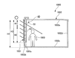
- FIG. 1 It is a figure which shows the room model provided with the lighting apparatus and the illumination light control system, Comprising: It is sectional drawing which follows the J-J 'line
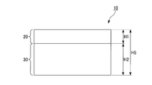
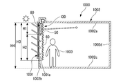
- FIG. 1A and 1B are diagrams showing a schematic configuration of a daylighting system according to a first embodiment of the present invention.
- FIG. 1A is a cross-sectional view
- FIG. 1B is a front view.
- reference numeral 1000 is a room model
- reference numeral 1001 is a window glass
- reference numeral 1002 is a room
- reference numeral 1002a is a ceiling
- reference numeral 1002b is a wall on which sunlight is incident
- reference numeral 1002c is a floor
- reference numeral 1002d is a wall A wall facing 1002b
- reference numeral 1003 indicates a person standing on the floor 1002c.
- FIG. 1000 is a room model
- reference numeral 1001 is a window glass
- reference numeral 1002 is a room
- reference numeral 1002a is a ceiling
- reference numeral 1002b is a wall on which sunlight is incident
- reference numeral 1002c is a floor
- reference numeral 1002d is
- the room 1002 is an office, and the cross section (XZ cross section) of the room 1002 is rectangular.
- the height H4 (the height from the floor 1002c to the ceiling 1002a) of the room 1002 is, for example, 2.7 m.
- the window glass 1001 is provided, for example, at a portion of 1.8 m from the ceiling 1002a on the wall 1002b side.
- the height H3 of the window glass 1001 is, for example, 1.8 m.
- the daylighting system 10 of the present embodiment is installed along a surface 1001a on the indoor (inside of the room 1002) side of the window glass 1001, and faces the upper side (the ceiling 1002a side) of the indoor side surface 1001a of the window glass 1001.
- a light shielding device 30 connected to the light transmitting device 20 and facing the lower side (floor 1002c side) of the indoor side surface 1001a of the window glass 1001. .
- the phrase “the light shielding device 30 is connected to the light transmission device 20” means that the light shielding device 30 hangs down below the light transmission device 20.
- the light transmission device 20 constituting the daylighting system 10 is provided on a portion of the indoor surface 1001a of the window glass 1001 that does not block the human field of view (a portion from the ceiling 1002a to, for example, 0.65 m).
- the height H1 of the light transmission device 20 is, for example, 0.65 m.
- the shading device 30 that constitutes the daylighting system 10 is provided on a portion of the indoor side surface 1001a of the window glass 1001 that blocks a human field of view (from the ceiling 1002a, for example, a portion from 0.65 m to 1.8 m). Yes.
- the height H2 of the light shielding device 30 is, for example, 1.15 m. That is, the height H5 of the daylighting system 10 is a height obtained by adding the height H1 of the light transmission device 20 and the height H2 of the light shielding device 30 and is, for example, 1.8 m.
- the light transmission device 20 includes a roll screen, a curtain, a vertical blind and the like made of a light transmissive material.
- light-transmitting materials include triacetyl cellulose (TAC) film, polyethylene terephthalate (PET) film, cycloolefin polymer (COP) film, polycarbonate (PC) film, polyethylene naphthalate (PEN) film, and polyether monkey.
- a light transmissive film (base material) such as a Hong (PES) film or a polyimide (PI) film is used.
- the light shielding device 30 is composed of a roll screen, a curtain, a vertical blind and the like made of a light-impermeable material.
- the light-impermeable material include aluminum foil, triacetyl cellulose (TAC), polyethylene terephthalate (PET), cycloolefin polymer (COP), polycarbonate (PC), polyethylene naphthalate (PEN), and polyethersulfone.
- a film (base material) formed by adding a pigment to a light-transmitting resin such as (PES) or polyimide (PI) and molding it into a predetermined shape is used.
- the daylighting system 10 of the present embodiment direct light that becomes glare light can be blocked by the light blocking device 30, and only light directed toward the ceiling 1002a can be guided indoors by the light transmitting device 20.
- the light transmission device 20 and the light shielding device 30 are configured by a roll screen, a curtain, a vertical blind, and the like, and therefore easily along the indoor surface 1001a of the window glass 1001. Can be installed.
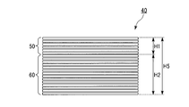
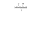
- FIGS. 1A and 1B are diagrams showing a schematic configuration of a daylighting system according to a second embodiment of the present invention.
- FIG. 2A is a cross-sectional view
- FIG. 2B is a front view.
- the daylighting system 40 of the present embodiment is installed along the indoor side (inside the room 1002) side surface 1001a of the window glass 1001, and faces the upper side (ceiling 1002a side) of the indoor side surface 1001a of the window glass 1001.
- a light shielding device 60 connected to the light transmitting device 50 and facing the lower side (floor 1002c side) of the indoor side surface 1001a of the window glass 1001. .
- the fact that the light shielding device 60 is connected to the light transmission device 50 means that the light shielding device 60 hangs below the light transmission device 50.
- the light transmission device 50 constituting the daylighting system 40 is provided on a portion of the indoor surface 1001a of the window glass 1001 that does not block the human field of view (a portion from the ceiling 1002a to, for example, 0.65 m).
- the height H1 of the light transmission device 50 is, for example, 0.65 m.
- the light shielding device 60 constituting the daylighting system 40 is provided on a portion of the indoor surface 1001a of the window glass 1001 that blocks a human view (from the ceiling 1002a, for example, a portion from 0.65 m to 1.8 m). Yes.
- the height H2 of the light shielding device 60 is, for example, 1.15 m. That is, the height H5 of the daylighting system 10 is a height obtained by adding the height H1 of the light transmission device 50 and the height H2 of the light shielding device 630, for example, 1.8 m.
- the light transmission device 50 includes a blind in which a large number of light-transmitting slats (louvers) are connected by a thread.
- a slat (louver) is an elongated belt-like plate.
- Examples of light-transmitting slats include triacetyl cellulose (TAC) film, polyethylene terephthalate (PET) film, cycloolefin polymer (COP) film, polycarbonate (PC) film, polyethylene naphthalate (PEN) film, and polyether monkey.
- a slat made of a light transmissive film (base material) such as a Hong (PES) film or a polyimide (PI) film is used.
- the light shielding device 60 is configured by a blind in which a large number of light-impermeable slats (louvers) are connected by a thread.
- the light-impermeable slats include aluminum slats, triacetyl cellulose (TAC), polyethylene terephthalate (PET), cycloolefin polymer (COP), polycarbonate (PC), polyethylene naphthalate (PEN), and polyether.
- a slat made of a light-impermeable film (base material) formed by adding a pigment to a light-transmitting resin such as sulfone (PES) or polyimide (PI) and molding it into a predetermined shape is used.
- the daylighting system 40 of the present embodiment direct light that becomes glare light can be blocked by the light shielding device 60, and only light directed toward the ceiling 1002a can be guided indoors by the light transmission device 50.
- the lighting system 10 of this embodiment can be easily installed along the indoor side surface 1001a of the window glass 1001. Further, the same effect can be obtained by removing the slats at the upper part of the blind. However, in this case, only the upper part of the thread remains, and when the blind is folded, the thread remains and cannot be efficiently stored. Also from this viewpoint, it is preferable to use a light-transmitting slat.
- FIGS. 3A and 3B are diagrams showing a schematic configuration of a daylighting system according to a third embodiment of the present invention.
- FIG. 3A is a cross-sectional view
- FIG. 3B is a cross-sectional view in which a part of FIG. 3A is enlarged.
- 3A and 3B the same components as those in the daylighting system of the first embodiment shown in FIGS. 1A and 1B and the daylighting system of the second embodiment shown in FIGS. 2A and 2B are denoted by the same reference numerals. The description is omitted.
- the daylighting system 70 of the present embodiment is installed along a surface 1001a on the indoor (inside of the room 1002) side of the window glass 1001, and faces the upper side (the ceiling 1002a side) of the indoor side surface 1001a of the window glass 1001.
- the daylighting device 80 provided on the indoor side surface 1001a side of the window glass 1001 with respect to the light transmission device 50.
- the daylighting device 80 is disposed between the light transmission device 50 and the indoor side surface 1001a of the window glass 1001.
- the daylighting device 80 includes a daylighting sheet 81, a first glass substrate (first substrate) 82 that holds the daylighting sheet 81, a light diffusion sheet 83, and a second side that holds the light diffusion sheet 83. It has a glass substrate (second substrate) 84 and a frame (support member) 85 that supports these components. A spacer 86 is disposed between the first glass substrate 82 and the light diffusion sheet 83.
- the daylighting sheet 81 has a light-transmitting base material 87 and a plurality of light-transmitting protrusions provided adjacent to one surface (light incident surface, outdoor side surface) 87a of the base material 87. 88.
- the protruding portion 88 is provided on one surface 87 a of the base material 87 so that the longitudinal direction thereof extends in a direction perpendicular to the height direction of the window glass 1001.
- the daylighting system 70 of the present embodiment direct light that becomes glare light can be blocked by the light shielding device 60, and only light directed toward the ceiling 1002a can be guided indoors by the light transmission device 50. Further, according to the daylighting system 70 of the present embodiment, the daylighting performance (light is inputted into the room 1002) by arranging the daylighting device 80 between the light transmitting device 50 and the indoor side surface 1001a of the window glass 1001. Performance). Moreover, since the light transmission device 20 and the light shielding device 30 are configured by blinds or the like, the daylighting system 70 of this embodiment can be easily installed along the indoor side surface 1001a of the window glass 1001.
- the daylighting device 80 may be disposed on the side opposite to the side facing the indoor side surface 1001a of the window glass 1001 in the light transmission device 50.
- the daylighting device 80 is not limited to the above-described structure, and may be, for example, a light shell or a louver that can reflect sunlight and send it indoors.
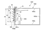
- FIGS. 4A and 4B are diagrams showing a schematic configuration of a daylighting system according to a fourth embodiment of the present invention.
- FIG. 4A is a cross-sectional view
- FIG. 4B is an enlarged perspective view of a part of FIG. 4A. 4A and 4B, the daylighting system of the first embodiment shown in FIGS. 1A and 1B, the daylighting system of the second embodiment shown in FIGS. 2A and 2B, and the third embodiment shown in FIGS. 3A and 3B.
- the same components as those of the daylighting system are designated by the same reference numerals, and the description thereof is omitted.
- the daylighting system 90 of the present embodiment is installed along the indoor side (inside the room 1002) side surface 1001a of the window glass 1001, and faces the upper side (ceiling 1002a side) of the indoor side surface 1001a of the window glass 1001.
- a light transmission device 50 provided on the floor, a light shielding device 60 connected to the light transmission device 50, and provided to face the lower side (floor 1002c side) of the indoor side surface 1001a of the window glass 1001, and the light transmission device 50
- a daylighting device 80 provided on the opposite side of the light transmitting device 50 from the side facing the indoor side surface 1001a of the window glass 1001.
- the multiple light-transmitting slats 51 constituting the light transmitting device 50 have a V-shaped cross section perpendicular to the longitudinal direction, and the apex angle ⁇ is, for example, It is 150 degrees.
- a large number of slats 51 are connected by a thread so that each apex angle ⁇ is convex toward the ceiling 1002a side of the room model 1000.
- the apex angle ⁇ is appropriately adjusted according to the direction of light guided into the room 1002.
- a scattering plate 52 for scattering light is provided on a surface 51a arranged on the ceiling 1002a side of the room 1002 in the slat 51. Examples of the scattering plate 52 include a white scattering plate made of white PET resin.
- the daylighting system 90 of the present embodiment direct light that becomes glare light can be blocked by the light shielding device 60.
- the surface 51a disposed on the ceiling 1002a side of the room 1002 in the many light-transmitting slats 51 constituting the light transmitting device 50 is used for scattering light. Since the scattering plate 52 is provided, the incident light transmitted through the window glass 1001 can be diffused by the scattering plate 52 and can be spread over the entire room 1002. Further, according to the daylighting system 90 of the present embodiment, since the light transmission device 50 and the light shielding device 60 are configured by blinds or the like, they can be easily installed along the indoor side surface 1001a of the window glass 1001.
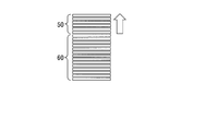
- FIGS. 5A and 5B are diagrams showing a schematic configuration of a daylighting system according to a fifth embodiment of the present invention.
- FIG. 5A is a cross-sectional view
- FIG. 5B is an enlarged perspective view of a part of FIG. 5A. 5A and 5B, the daylighting system of the first embodiment shown in FIGS. 1A and 1B, the daylighting system of the second embodiment shown in FIGS. 2A and 2B, and the third embodiment shown in FIGS. 3A and 3B.
- the same components as those of the lighting system of the embodiment and the lighting system of the fourth embodiment shown in FIGS. 4A and 4B are denoted by the same reference numerals, and the description thereof is omitted.
- the daylighting system 100 is installed along the indoor surface (inside the room 1002) side 1001a of the window glass 1001, and faces the upper side (ceiling 1002a side) of the indoor side surface 1001a of the window glass 1001.
- a light transmission device 50 provided on the floor, a light shielding device 60 connected to the light transmission device 50, and provided to face the lower side (floor 1002c side) of the indoor side surface 1001a of the window glass 1001, and the light transmission device 50
- a daylighting device 80 provided on the opposite side of the light transmitting device 50 from the side facing the indoor side surface 1001a of the window glass 1001.
- the slat 51 is, for example, a film in which transparent particles (not shown) that scatter or transmit light are uniformly dispersed.
- the daylighting system 100 of the present embodiment direct light that becomes glare light can be blocked by the light shielding device 60.
- a large number of light-transmitting slats 51 constituting the light transmitting device 50 are obtained by uniformly dispersing therein transparent particles that scatter or transmit light. Therefore, incident light that has passed through the window glass 1001 can be diffused by the transparent particles and can be distributed throughout the room 1002.
- the light transmission device 50 and the light shielding device 60 are configured by blinds or the like, they can be easily installed along the indoor side surface 1001a of the window glass 1001.
- FIGS. 6A and 6B are diagrams showing a schematic configuration of a daylighting system according to a sixth embodiment of the present invention.
- FIG. 6A is a sectional view
- FIG. 6B is an enlarged sectional view of a part of FIG. 6A.
- 7A and 7B are diagrams showing a schematic configuration of a daylighting system according to a sixth embodiment of the present invention.
- FIG. 7A is an enlarged perspective view of a part of FIG. 6A
- FIG. 7B is an AA view of FIG. It is sectional drawing which follows a line. 6A, 6B, 7A and 7B, the daylighting system of the first embodiment shown in FIGS. 1A and 1B, the daylighting system of the second embodiment shown in FIGS.
- the daylighting system 110 of the present embodiment is installed along the indoor side (inside the room 1002) side surface 1001a of the window glass 1001, and faces the upper side (ceiling 1002a side) of the indoor side surface 1001a of the window glass 1001.
- the daylighting device 120 is disposed between the light transmitting device 50 and the indoor side surface 1001a of the window glass 1001.
- the daylighting device 120 includes a daylighting sheet 81, a first glass substrate (first substrate) 82 that holds the daylighting sheet 81, and a frame (supporting member) 85 that supports these components.
- the daylighting sheet 81 has a light-transmitting base material 87 and a plurality of light-transmitting protrusions provided adjacent to one surface (light incident surface, outdoor side surface) 87a of the base material 87. 88.
- the protruding portion 88 is provided on one surface of the base material 87 so that the longitudinal direction thereof extends in a direction perpendicular to the height direction of the window glass 1001.
- the light transmissive slats 51 constituting the light transmitting device 50 have a V-shaped cross section perpendicular to the longitudinal direction, and the apex angle ⁇ is For example, 150 degrees.
- a large number of slats 51 are connected by a thread so that each apex angle ⁇ is convex toward the ceiling 1002a side of the room model 1000. Note that the apex angle ⁇ is appropriately adjusted according to the direction of light guided into the room 1002.
- a plurality of light-transmitting protrusions 53 that are adjacent to each other along the longitudinal direction of the slat 51 are provided on a surface 51 a of the slat 51 that is disposed on the ceiling 1002 a side of the room model 1000.
- the protrusion 53 has a semicircular shape whose cross section perpendicular to the longitudinal direction is convex on the side opposite to the surface 51a.
- the protrusion 53 is provided on the surface 51 a so that its longitudinal direction extends in a direction perpendicular to the longitudinal direction of the slat 51.
- the protrusion 53 has anisotropy in the light diffusion direction that is highly diffused in the horizontal direction.
- the daylighting system 110 of the present embodiment direct light that becomes glare light can be blocked by the light blocking device 60.
- the surface 51a disposed on the ceiling 1002a side of the room model 1000 in the many light transmissive slats 51 constituting the light transmission device 50 is arranged in the longitudinal direction of the slats 51.
- a plurality of light-transmitting protrusions 53 adjacent to each other are provided along the light source. Therefore, incident light transmitted through the window glass 1001 is highly diffused in the horizontal direction by the protrusions 53 and guided into the room 1002. Can do.
- the daylighting system 110 of the present embodiment since the slat 51 has the protrusion 53, there is no need to provide a light diffusion sheet as in the third embodiment described above, and the daylighting system 110 is reduced in weight. And can be easily installed along the indoor side surface 1001a of the window glass 1001.
- the anisotropic diffusion function is imparted by providing the protrusion 53 on the surface 51a of the slat 51, but the method of imparting the anisotropic diffusion function is not limited to this.
- an anisotropic diffusion function may be imparted by attaching an anisotropic diffusion film to the surface 51 a of the slat 51.
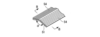
- FIGS. 8A to 8C are diagrams showing a schematic configuration of a daylighting system according to a seventh embodiment of the present invention.
- FIG. 8A is a sectional view
- FIG. 8B is an enlarged perspective view of a part of FIG. 8A
- FIG. It is sectional drawing which follows the BB line of FIG. 8B.
- 8A to 8C the daylighting system of the first embodiment shown in FIGS. 1A and 1B, the daylighting system of the second embodiment shown in FIGS. 2A and 2B, and the third embodiment shown in FIGS. 3A and 3B.
- the daylighting system 130 of the present embodiment is installed along the indoor side (inside the room 1002) side surface 1001a of the window glass 1001, and faces the upper side (ceiling 1002a side) of the indoor side surface 1001a of the window glass 1001.
- the daylighting device 80 provided on the indoor side surface 1001a side of the window glass 1001 with respect to the light transmission device 50.
- the daylighting device 80 is disposed between the light transmitting device 50 and the indoor side surface 1001 a of the window glass 1001.
- a large number of light-transmitting slats 51 constituting the light transmitting device 50 have a V-shaped cross section perpendicular to the longitudinal direction, and the apex angle ⁇ is For example, 150 degrees.
- a large number of slats 51 are connected by a thread so that each apex angle ⁇ is convex toward the ceiling 1002a side of the room model 1000. Note that the apex angle ⁇ is appropriately adjusted according to the direction of light guided into the room 1002.
- a plurality of light-transmitting prisms 54 that are adjacent to each other along the longitudinal direction of the slat 51 are provided on a surface 51 a that is disposed on the ceiling 1002 a side of the room 1002 in the slat 51.
- the prism 54 has a cross-sectional shape perpendicular to the longitudinal direction, and has a triangular shape that is convex on the side opposite to the surface 51a.
- the prism 54 is provided on the surface 51 a so that the longitudinal direction thereof extends along the longitudinal direction of the slat 51.
- the prism 54 changes the direction of incident light incident on the prism 54 in the height H4 direction (vertical direction) of the room 1002.
- direct light that becomes glare light can be blocked by the light blocking device 60.
- the direction of incident light directed toward the ceiling 1002a via the daylighting device 80 can be further changed.
- the direction of incident light can be adjusted according to the season and time even if the same daylighting device 80 is used. Fine adjustments can be made.
- the prism 54 may have two or more types of structures depending on the distance from the ceiling 1002a.
- the prism 54 in the slat 51 that constitutes a region near the ceiling 1002a in the light transmission device 50, the prism 54 has a structure that bends incident light in the horizontal direction, and in the light transmission device 50, a region that is away from the ceiling 1002a.
- the prism 54 In the constituting slat 51, the prism 54 has a structure that bends incident light toward the ceiling 1002a.
- the structure of the prism 54 to two or more types according to the distance from the ceiling 1002a, the direction in which incident light is bent can be corrected according to the position (height) of the slat 51.
- the daylighting system 130 of this embodiment even if the same daylighting apparatus 80 is used, it can correct
- the daylighting system 130 of the present embodiment can be easily installed along the indoor side surface 1001a of the window glass 1001 because the light transmission device 50 and the light shielding device 60 are constituted by blinds or the like.
- FIG. 9 is a sectional view showing a schematic configuration of a daylighting system according to the eighth embodiment of the present invention.
- the daylighting system 140 of the present embodiment is installed along the indoor (inside of the room) side surface 1001a of the window glass 1001, and is provided so as to face the upper side (ceiling side) of the indoor side surface 1001a of the window glass 1001.
- the daylighting device 150 is provided on the indoor side surface 1001 a of the window glass 1001.
- the daylighting device 150 includes a daylighting sheet 153 having a light-transmitting base material 151 and a plurality of light-transmitting protrusions 152 provided adjacent to one surface 151 a of the base material 151. .
- the protrusion 152 is provided on one surface 151 a of the base material 151 so that the longitudinal direction thereof extends in a direction perpendicular to the height direction of the window glass 1001.
- the daylighting system 140 of the present embodiment direct light that becomes glare light can be blocked by the light shielding device 60, and only light directed toward the ceiling 1002a can be guided indoors by the light transmission device 50.
- the daylighting device 150 is provided on the indoor side surface 1001a of the window glass 1001, the configuration is simplified and along the indoor side surface 1001a of the window glass 1001. It can be installed easily.
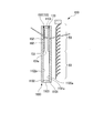
- FIG. 10 is a sectional view showing a schematic configuration of a daylighting system according to the ninth embodiment of the present invention.
- the daylighting system 160 of this embodiment is installed along the indoor (inside the room) side surface 1100a of the window glass 1100, and is provided so as to face the upper side (ceiling side) of the indoor side surface 1100a of the window glass 1100.
- the light diffusing device 170 made of a light diffusing sheet provided at a position facing the daylighting device 150.
- the window glass 1100 is a multi-layer glass in which a pair of glass plates 1101 and 1102 are arranged to face each other with a space therebetween via a spacer 1103.
- the glass plate 1101 disposed on the indoor side is referred to as a first glass plate 1101
- the glass plate 1102 disposed on the outdoor side is referred to as a second glass plate 1102.
- the daylighting device 150 is provided in the window glass 1100, that is, between the first glass plate 1101 and the second glass plate 1102. More specifically, the daylighting device 150 is provided on a surface 1102 a of the second glass plate 1102 that faces the first glass plate 1101.
- a light diffusing device 170 is provided in the window glass 1100, that is, between the first glass plate 1101 and the second glass plate 1102. More specifically, the light diffusing device 170 is provided on a surface 1101 a of the first glass plate 1101 that faces the second glass plate 1102.
- the daylighting system 160 of the present embodiment the direct light that becomes the glare light can be blocked by the light blocking device 60, and only the light directed toward the ceiling 1002a can be guided into the room by the light transmitting device 50. Further, the daylighting system 160 of the present embodiment includes a daylighting device 150 and a light diffusing device 170 in a window glass 1100 made of multi-layer glass, so that the configuration is simplified and the indoor side of the window glass 1001 is arranged. It can be easily installed along the surface 1001a.
- FIG. 11 is sectional drawing which shows schematic structure of the lighting system which is 10th Embodiment of this invention. 11, the same components as those of the daylighting system of the first embodiment shown in FIGS. 1A and 1B, the daylighting system of the eighth embodiment shown in FIG. 9, and the daylighting system of the ninth embodiment shown in FIG. Are denoted by the same reference numerals, and the description thereof is omitted.
- the daylighting system 180 according to the present embodiment is installed along the indoor surface 1100a of the window glass 1100, and is provided so as to face the upper side (ceiling side) of the indoor surface 1100a of the window glass 1100.
- the light diffusing device 170 made of a light diffusing sheet provided at a position facing the daylighting device 150.
- the daylighting device 150 is provided in the window glass 1100, that is, between the first glass plate 1101 and the second glass plate 1102. More specifically, the daylighting device 150 is provided on a surface 1101 a of the first glass plate 1101 that faces the second glass plate 1102.
- a light diffusing device 170 is provided in the window glass 1100, that is, between the first glass plate 1101 and the second glass plate 1102. More specifically, the light diffusing device 170 is provided on a surface 1102 a of the second glass plate 1102 facing the first glass plate 1101.
- the daylighting system 180 of this embodiment the direct light that becomes glare light can be blocked by the light shielding device 60, and only the light directed toward the ceiling 1002a can be guided into the room by the light transmitting device 50.
- the daylighting system 180 of the present embodiment includes a daylighting device 150 and a light diffusion device 170 in a window glass 1100 made of multilayer glass, so that the configuration is simplified and the indoor side of the window glass 1001 is arranged. It can be easily installed along the surface 1001a.
- FIG. 12 is sectional drawing which shows schematic structure of the lighting system which is 11th Embodiment of this invention. 12, the same components as those of the daylighting system of the first embodiment shown in FIGS. 1A and 1B, the daylighting system of the eighth embodiment shown in FIG. 9, and the daylighting system of the ninth embodiment shown in FIG. Are denoted by the same reference numerals, and the description thereof is omitted.
- the daylighting system 190 of this embodiment is installed along the indoor (inside the room) side surface 1100a of the window glass 1100 and is provided so as to face the upper side (ceiling side) of the indoor side surface 1100a of the window glass 1100.
- the light diffusing device 170 made of a light diffusing sheet provided at a position facing the daylighting device 150.
- the daylighting device 150 is provided in the window glass 1100, that is, between the first glass plate 1101 and the second glass plate 1102. More specifically, the daylighting device 150 is provided on a surface 1101 a of the first glass plate 1101 that faces the second glass plate 1102. Further, the light diffusing device 170 is provided on the surface 1101b of the first glass plate 1101 opposite to the surface 1101a facing the second glass plate 1102.
- the daylighting device 150 is provided on the surface 1101a of the first glass plate 1101 facing the second glass plate 1102, and the light diffusing device 170 is the first glass plate 1101. Is provided on the surface 1101b opposite to the surface 1101a opposite to the second glass plate 1102 in FIG. 1, the configuration is simplified, and the window glass 1001 can be easily installed along the indoor surface 1001a. it can.
- FIG. 13A is a cross-sectional view illustrating a schematic configuration of a daylighting system according to a twelfth embodiment of the present invention
- FIGS. 13B to 13D are front views illustrating a schematic configuration of a daylighting system according to a twelfth embodiment of the present invention. It is. 13A to 13D, the daylighting system of the first embodiment shown in FIGS. 1A and 1B, the daylighting system of the second embodiment shown in FIGS. 2A and 2B, and the third embodiment shown in FIGS. 3A and 3B.
- the same components as those of the daylighting system are designated by the same reference numerals, and the description thereof is omitted.
- the daylighting system 200 is installed along the indoor surface (inside the room 1002) side 1001a of the window glass 1001, and faces the upper side (ceiling 1002a side) of the indoor side surface 1001a of the window glass 1001.
- a light transmission device 50 provided on the floor, a light shielding device 60 connected to the light transmission device 50, and provided to face the lower side (floor 1002c side) of the indoor side surface 1001a of the window glass 1001, and the light transmission device 50
- the daylighting device 80 provided on the indoor side surface 1001a side of the window glass 1001 with respect to the light transmission device 50.
- the light transmission device 50 and the light shielding device 60 can be moved up and down independently along the indoor surface 1001a of the window glass 1001.
- the light transmission device 50 and the light shielding device 60 can be moved up and down by different strings or the like.
- the slats can be opened and closed independently.
- the light transmission device 50 is opened as shown in FIG. 13B.
- the light transmissive device 50 is wound up to close the light transmissive device 50, and the entire indoor surface 1001a of the window glass 1001 is shielded from light. Cover with device 60.
- the light shielding device 60 has such a size that the entire surface 1001a on the indoor side of the window glass 1001 can be covered with the light shielding device 60 with the light transmitting device 50 closed. Further, as shown in FIG.
- the entire indoor surface 1001a of the window glass 1001 can be in a state not covered by the daylighting system 200.
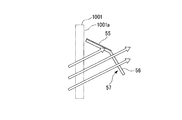
- FIGS. 14A to 14C are diagrams showing a schematic configuration of a daylighting system according to a thirteenth embodiment of the present invention.
- FIG. 14A is a perspective view
- FIG. 14B is a sectional view
- FIG. 14C is a sectional view.
- the light transmission device 50 is provided on the indoor side surface 1001a of the window glass 1001 described above.
- a composite slat 57 having a light shielding part 55 and a light transmission part 56 connected to the light shielding part 55 and inclined with respect to the light shielding part 55.
- the light transmission device 50 is composed of a blind in which a large number of composite slats 57 are connected by a thread.
- the multiple composite slats 57 constituting the light transmission device 50 have a V-shaped cross section perpendicular to the longitudinal direction, and the apex angle ⁇ is, for example, 150 degrees.
- the multiple composite slats 57 are connected by a thread so that each apex angle ⁇ is convex toward the ceiling 1002a side of the room model 1000.
- the apex angle ⁇ is appropriately adjusted according to the direction of light guided into the room 1002.
- the light transmitting portion 56 is made of the same material as the light transmitting slat.
- the light shielding portion 55 is made of the same material as the light impermeable slat.
- the composite slat 57 is rotated, and the light shielding portion 55 is arranged along the indoor side surface 1001 a of the window glass 1001.
- the amount of incident light on the can be reduced.
- the light incident on the window glass 1001 is directed only in the direction of the ceiling 1002a.
- FIG. 14C by rotating the composite slat 57 and arranging the light transmitting portion 56 so as to face the indoor side surface 1001a side of the window glass 1001, the incident light into the room 1002 is arranged. The amount can be increased.
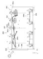
- FIG. 15 is a diagram showing a room model including a daylighting system and an illumination dimming system, and is a cross-sectional view taken along the line JJ ′ of FIG.
- FIG. 16 is a plan view showing the ceiling of the room model 2000.
- the ceiling material constituting the ceiling 2003a of the room 2003 into which external light is introduced may have high light reflectivity.
- a light-reflective ceiling material 2003A is installed on the ceiling 2003a of the room 2003 as a ceiling material having light reflectivity.
- the light-reflective ceiling material 2003A is intended to promote the introduction of external light from the daylighting system 2010 installed in the window 2002 into the interior of the room, and is installed on the ceiling 2003a near the window. Yes. Specifically, it is installed in a predetermined area E (an area about 3 m from the window 2002) of the ceiling 2003a.
- the light-reflective ceiling material 2003A is configured to transmit the outside light introduced into the room through the window 2002 in which the daylighting system 2010 (the daylighting system of any of the above-described embodiments) is installed. Efficiently leads to the back. Outside light introduced from the daylighting system 2010 toward the indoor ceiling 2003a is reflected by the light-reflective ceiling material 2003A and changes its direction to illuminate the desk surface 2005a of the desk 2005 placed in the interior of the room. The effect of brightening the desk top surface 2005a is exhibited.
- the daylighting system 2010 the daylighting system of any of the above-described embodiments
- the light-reflective ceiling material 2003A may be diffusely reflective or specularly reflective, but has the effect of brightening the desk top surface 2005a of the desk 2005 placed in the interior of the room, and is in the room. In order to achieve both effects of suppressing glare rays that are unpleasant for humans, it is preferable that the characteristics of the two are appropriately mixed.
- the light introduced into the room by the daylighting system 2010 is directed to the ceiling near the window 2002, but the amount of light in the vicinity of the window 2002 is often sufficient. Therefore, by using together the light-reflective ceiling material 2003A as described above, the light incident on the ceiling (region E) in the vicinity of the window can be distributed toward the back of the room where the amount of light is small compared to the window.
- the light-reflective ceiling material 2003A is formed by, for example, embossing a metal plate such as aluminum with unevenness of about several tens of microns, or depositing a metal thin film such as aluminum on the surface of a resin substrate on which similar unevenness is formed. Can be created. Or the unevenness
- the emboss shape formed on the light-reflective ceiling material 2003A it is possible to control the light distribution characteristics and the light distribution in the room. For example, when embossing is performed in a stripe shape extending toward the back of the room, the light reflected by the light-reflective ceiling material 2003A is in the left-right direction of the window 2002 (direction intersecting the longitudinal direction of the unevenness). spread. When the size and direction of the window 2002 in the room 2003 are limited, the light is reflected in the horizontal direction by the light-reflective ceiling material 2003A and the interior of the room 2003 is moved to the back of the room. It can be reflected toward.
- the daylighting system 2010 is used as part of the lighting dimming system in the room 2003.
- the lighting dimming system includes, for example, a daylighting system 2010, a plurality of indoor lighting devices 2007, a solar radiation adjusting device 2008 installed in a window, a control system thereof, and a light-reflective ceiling material 2003A installed on a ceiling 2003a. And the constituent members of the entire room including
- a daylighting system 2010 is installed on the upper side, and a solar radiation adjusting device 2008 is installed on the lower side.
- a blind is installed as the solar radiation adjustment device 2008, but this is not a limitation.
- a plurality of indoor lighting devices 2007 are arranged in a grid in the left-right direction (Y direction) of the window 2002 and the depth direction (X direction) of the room.
- the plurality of indoor lighting devices 2007 together with the daylighting system 2010 constitute an entire lighting system of the room 2003.
- the ceiling length L 1 in the left-right direction (Y-direction) is 18m
- the length L 2 in the depth direction of the room 2003 (X direction) of the office 9m windows 2002 2003a Indicates.
- the indoor lighting devices 2007 are arranged in a grid pattern with an interval P of 1.8 m in the horizontal direction (Y direction) and the depth direction (X direction) of the ceiling 2003a. More specifically, 50 indoor lighting devices 2007 are arranged in 10 rows (Y direction) ⁇ 5 columns (X direction).
- the indoor lighting device 2007 includes an indoor lighting fixture 2007a, a brightness detection unit 2007b, and a control unit 2007c.
- the indoor lighting fixture 2007a is configured by integrating the brightness detection unit 2007b and the control unit 2007c. It is.
- the indoor lighting device 2007 may include a plurality of indoor lighting fixtures 2007a and a plurality of brightness detection units 2007b. However, one brightness detector 2007b is provided for each indoor lighting device 2007a.
- the brightness detection unit 2007b receives the reflected light of the irradiated surface illuminated by the indoor lighting fixture 2007a, and detects the illuminance of the irradiated surface.
- the brightness detector 200b detects the illuminance of the desk surface 2005a of the desk 2005 placed indoors.
- the control units 2007c provided for each room lighting device 2007 are connected to each other.
- Each indoor lighting device 2007 is configured such that the illuminance of the desk top surface 2005a detected by each brightness detecting unit 2007b becomes a constant target illuminance L0 (for example, average illuminance: 750 lx) by the control units 2007c connected to each other.
- Feedback control is performed to adjust the light output of the LED lamp of each indoor lighting fixture 2007a.
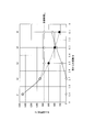
- FIG. 17 is a graph showing the relationship between the illuminance of light (natural light) taken indoors by the daylighting device and the illuminance (illumination dimming system) by the indoor lighting device.
- the vertical axis represents the illuminance (lx) on the desk surface
- the horizontal axis represents the distance (m) from the window.
- the broken line in the figure indicates the target illuminance in the room.
- the desk surface illuminance due to the light collected by the daylighting system 2010 is brighter in the vicinity of the window, and the effect decreases as the distance from the window increases.
- the daylighting system 2010 is used in combination with an indoor lighting device 2007 that compensates for the illuminance distribution in the room.
- the indoor lighting device 2007 installed on the indoor ceiling detects the average illuminance below each device by the brightness detection unit 2007b, and is dimmed and controlled so that the desk surface illuminance of the entire room becomes a constant target illuminance L0. Lights up.
- the S1 and S2 rows installed in the vicinity of the window are hardly lit, and are lit while increasing the output toward the back of the room with the S3, S4, and S5 rows.
- the desk surface of the room is illuminated by the sum of the illuminance by natural lighting and the illumination by the interior lighting device 2007, and the illuminance of the desk surface is 750 lx (“JIS Z9110 illumination” which is sufficient for work throughout the room. "Recommended maintenance illuminance in the office of" General "" can be realized.
- the daylighting system 2010 and the illumination dimming system indoor lighting device 2007
- One embodiment of the present invention can be used for a window glass, a roll screen, and a daylighting louver.
Landscapes
- Engineering & Computer Science (AREA)
- General Engineering & Computer Science (AREA)
- Physics & Mathematics (AREA)
- Structural Engineering (AREA)
- Civil Engineering (AREA)
- General Physics & Mathematics (AREA)
- Optics & Photonics (AREA)
- Architecture (AREA)
- Life Sciences & Earth Sciences (AREA)
- Sustainable Development (AREA)
- Non-Portable Lighting Devices Or Systems Thereof (AREA)
- Optical Elements Other Than Lenses (AREA)
Abstract
窓ガラス(1001)の屋内側の面(1001a)に沿って設置され、窓ガラス(1001)の屋内側の面(1001a)の上側に対向するように設けられる光透過装置(20)と、光透過装置(20)に連接し、窓ガラス(1001)の屋内側の面(1001a)の下側に対向するように設けられる遮光装置(30)と、を備えてなる採光システム(10)。
Description
本発明は、採光システムに関する。
本願は、2015年4月30日に、日本に出願された特願2015-093619号に基づき優先権を主張し、その内容をここに援用する。
本願は、2015年4月30日に、日本に出願された特願2015-093619号に基づき優先権を主張し、その内容をここに援用する。
窓ガラスに入射する日光等の外光を効率よく室内に導くために、窓ガラスの一面に沿って、採光フィルムを含む採光装置が設けられることが知られている(例えば、特許文献1参照)。
窓ガラスの一面に沿って採光装置を設ける際、グレア光となる直射光を遮断し、採光装置を介して天井方向に向けられた光のみを室内に導くためには、窓ガラスの一面おける採光装置よりも下側の領域を遮光する必要がある。しかしながら、遮光を目的として、従来のブラインドやロールスクリーンを設けた場合、窓全面を遮光した態様、または、窓全面もしくは窓の下側の領域が開口した態様(ブラインドやロールスクリーンが窓ガラスの一面に沿って巻き上げられた態様)をなすことしかできなかった。
例えば、採光装置よりも下側に、採光装置に連接して、ブラインドやロールスクリーンを設ける場合、別途、ブラインドやロールスクリーンを巻き上げて収納するためのヘッドボックスを設ける必要がある。この場合、建物自体の工事が必要であるばかりではなく、その工事が大掛かりになるという課題があった。
また、採光装置よりも下側に、採光装置に吊り下げて、ブラインドやロールスクリーンを設ける場合、採光装置とブラインド等の全体の質量が大きくなる。この場合、採光装置を固定するための固定具に相当の強度が必要であるばかりではなく、採光装置の重心がずれて、その採光面を窓ガラスの一面に対して平行に配置することが難しいという課題があった。
また、採光装置よりも下側に、採光装置に吊り下げて、ブラインドやロールスクリーンを設ける場合、採光装置とブラインド等の全体の質量が大きくなる。この場合、採光装置を固定するための固定具に相当の強度が必要であるばかりではなく、採光装置の重心がずれて、その採光面を窓ガラスの一面に対して平行に配置することが難しいという課題があった。
本発明の一態様は、上記事情に鑑みてなされたものであって、設置が容易であり、グレア光となる直射光を遮断し、天井方向に向けられた光のみを室内に導くことができる採光システムを提供することを目的とする。
本発明の1つの態様の採光システムは、窓ガラスの屋内側の面に沿って設置される採光システムであって、前記窓ガラスの屋内側の面の上側に対向するように設けられる光透過装置と、該光透過装置に連接し、前記窓ガラスの屋内側の面の下側に対向するように設けられる遮光装置と、を備えてなる。
本発明の1つの態様の採光システムにおいて、前記光透過装置は、光透過スラットを有し、前記遮光装置は、遮光スラットを有していてもよい。
本発明の1つの態様の採光システムにおいて、前記光透過装置に対向するように設けられる採光装置を備えていてもよい。
本発明の1つの態様の採光システムにおいて、前記採光装置は、光透過性を有する基材と、該基材の一面に互いに隣接して設けられた複数の光透過性を有する突起部と、有していてもよい。
本発明の1つの態様の採光システムにおいて、前記光透過装置は、水平方向に高拡散である光拡散方向の異方性を有していてもよい。
本発明の1つの態様の採光システムにおいて、前記光透過装置は、鉛直方向に光の向きを変化させるプリズム構造を有していてもよい。
本発明の1つの態様の採光システムにおいて、天井からの距離に応じて、前記プリズム構造を2種以上有していてもよい。
本発明の1つの態様の採光システムにおいて、前記採光装置は、前記窓ガラスの屋内側の面に設けられていてもよい。
本発明の1つの態様の採光システムにおいて、前記窓ガラスは、一対のガラス板が間隔を隔てて対向して配置された複層ガラスからなり、前記採光装置は、前記複層ガラス内に設けられていてもよい。
本発明の1つの態様の採光システムにおいて、前記採光装置と対向する位置に光を拡散する光拡散装置が設けられていてもよい。
本発明の1つの態様の採光システムにおいて、前記光透過装置は、前記窓ガラスの一面に設けられた遮光部と、該遮光部に連接し、該遮光部に対して傾斜する光透過部とを有する複合スラットを有する複合スラットを有していてもよい。
本発明の1つの態様の採光システムにおいて、前記光透過装置と前記遮光装置は、独立して、前記窓ガラスの一面に沿って昇降可能であってもよい。前記光透過装置がブラインド型である場合には、スラットの開閉も独立して操作できることが好ましい。
本発明の一態様によれば、設置が容易であり、グレア光となる直射光を遮断し、天井方向に向けられた光のみを室内に導くことができる採光システムを提供することができる。
本発明の採光システムの実施の形態について説明する。
なお、本実施の形態は、発明の趣旨をより良く理解させるために具体的に説明するものであり、特に指定のない限り、本発明を限定するものではない。
なお、本実施の形態は、発明の趣旨をより良く理解させるために具体的に説明するものであり、特に指定のない限り、本発明を限定するものではない。
[採光システム]
(第1実施形態)
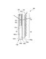
図1A及び図1Bは、本発明の第1実施形態である採光システムの概略構成を示す図であり、図1Aは断面図、図1Bは正面図である。
図1A、図1Bにおいて、符合1000は部屋モデル、符号1001は窓ガラス、符号1002は部屋、符号1002aは天井、符号1002bは太陽光が入射する側の壁、符号1002cは床、符号1002dは壁1002bと対面の壁、符号1003は床1002cに立っている人を示す。
図1Aに示すように、部屋1002はオフィスを例としており、部屋1002の断面(XZ断面)の形状は矩形である。部屋1002の高さH4(床1002cから天井1002aまでの高さ)は、例えば、2.7mである。窓ガラス1001は、壁1002b側において、天井1002aから、例えば、1.8mの部分に設けられている。窓ガラス1001の高さH3は、例えば、1.8mである。
(第1実施形態)
図1A及び図1Bは、本発明の第1実施形態である採光システムの概略構成を示す図であり、図1Aは断面図、図1Bは正面図である。
図1A、図1Bにおいて、符合1000は部屋モデル、符号1001は窓ガラス、符号1002は部屋、符号1002aは天井、符号1002bは太陽光が入射する側の壁、符号1002cは床、符号1002dは壁1002bと対面の壁、符号1003は床1002cに立っている人を示す。
図1Aに示すように、部屋1002はオフィスを例としており、部屋1002の断面(XZ断面)の形状は矩形である。部屋1002の高さH4(床1002cから天井1002aまでの高さ)は、例えば、2.7mである。窓ガラス1001は、壁1002b側において、天井1002aから、例えば、1.8mの部分に設けられている。窓ガラス1001の高さH3は、例えば、1.8mである。
本実施形態の採光システム10は、窓ガラス1001の屋内(部屋1002の内部)側の面1001aに沿って設置され、窓ガラス1001の屋内側の面1001aの上側(天井1002a側)に対向するように設けられる光透過装置20と、光透過装置20に連接し、窓ガラス1001の屋内側の面1001aの下側(床1002c側)に対向するように設けられる遮光装置30と、を備えている。
遮光装置30が光透過装置20に連接しているとは、遮光装置30が光透過装置20の下側に垂れ下がっていることを言う。
遮光装置30が光透過装置20に連接しているとは、遮光装置30が光透過装置20の下側に垂れ下がっていることを言う。
採光システム10を構成する光透過装置20は、窓ガラス1001の屋内側の面1001aにおいて、人間の視界を遮らない部分(天井1002aから、例えば、0.65mまでの部分)に設けられている。光透過装置20の高さH1は、例えば、0.65mである。
採光システム10を構成する遮光装置30は、窓ガラス1001の屋内側の面1001aにおいて、人間の視界を遮る部分(天井1002aから、例えば、0.65mから1.8mまでの部分)に設けられている。遮光装置30の高さH2は、例えば、1.15mである。
すなわち、採光システム10の高さH5は、光透過装置20の高さH1と遮光装置30の高さH2を足した高さであり、例えば、1.8mである。
採光システム10を構成する遮光装置30は、窓ガラス1001の屋内側の面1001aにおいて、人間の視界を遮る部分(天井1002aから、例えば、0.65mから1.8mまでの部分)に設けられている。遮光装置30の高さH2は、例えば、1.15mである。
すなわち、採光システム10の高さH5は、光透過装置20の高さH1と遮光装置30の高さH2を足した高さであり、例えば、1.8mである。
光透過装置20は、光透過性の材料からなるロールスクリーン、カーテン、縦型ブラインド等から構成されている。
光透過性の材料としては、例えば、トリアセチルセルロース(TAC)フィルム、ポリエチレンテレフタレート(PET)フィルム、シクロオレフィンポリマー(COP)フィルム、ポリカーボネート(PC)フィルム、ポリエチレンナフタレート(PEN)フィルム、ポリエーテルサルホン(PES)フィルム、ポリイミド(PI)フィルム等の光透過性のフィルム(基材)が用いられる。
光透過性の材料としては、例えば、トリアセチルセルロース(TAC)フィルム、ポリエチレンテレフタレート(PET)フィルム、シクロオレフィンポリマー(COP)フィルム、ポリカーボネート(PC)フィルム、ポリエチレンナフタレート(PEN)フィルム、ポリエーテルサルホン(PES)フィルム、ポリイミド(PI)フィルム等の光透過性のフィルム(基材)が用いられる。
遮光装置30は、光不透過性の材料からなるロールスクリーン、カーテン、縦型ブラインド等から構成されている。
光不透過性の材料としては、例えば、アルミニウム箔、トリアセチルセルロース(TAC)、ポリエチレンテレフタレート(PET)、シクロオレフィンポリマー(COP)、ポリカーボネート(PC)、ポリエチレンナフタレート(PEN)、ポリエーテルサルホン(PES)、ポリイミド(PI)等の光透過性の樹脂に顔料を添加して、所定の形状に成形してなるフィルム(基材)等が用いられる。
光不透過性の材料としては、例えば、アルミニウム箔、トリアセチルセルロース(TAC)、ポリエチレンテレフタレート(PET)、シクロオレフィンポリマー(COP)、ポリカーボネート(PC)、ポリエチレンナフタレート(PEN)、ポリエーテルサルホン(PES)、ポリイミド(PI)等の光透過性の樹脂に顔料を添加して、所定の形状に成形してなるフィルム(基材)等が用いられる。
本実施形態の採光システム10によれば、遮光装置30によりグレア光となる直射光を遮断し、光透過装置20により天井1002aの方向に向けられた光のみを室内に導くことができる。また、本実施形態の採光システム10は、光透過装置20および遮光装置30が、ロールスクリーン、カーテン、縦型ブラインド等から構成されるため、窓ガラス1001の屋内側の面1001aに沿って容易に設置することができる。
(第2実施形態)
図2A及び図2Bは、本発明の第2実施形態である採光システムの概略構成を示す図であり、図2Aは断面図、図2Bは正面図である。図2A及び図2Bにおいて、図1A及び図1Bに示した第1実施形態の採光システムと同一の構成要素には同一符号を付して、その説明を省略する。
本実施形態の採光システム40は、窓ガラス1001の屋内(部屋1002の内部)側の面1001aに沿って設置され、窓ガラス1001の屋内側の面1001aの上側(天井1002a側)に対向するように設けられる光透過装置50と、光透過装置50に連接し、窓ガラス1001の屋内側の面1001aの下側(床1002c側)に対向するように設けられる遮光装置60と、を備えている。
遮光装置60が光透過装置50に連接しているとは、遮光装置60が光透過装置50の下側に垂れ下がっていることを言う。
採光システム40を構成する光透過装置50は、窓ガラス1001の屋内側の面1001aにおいて、人間の視界を遮らない部分(天井1002aから、例えば、0.65mまでの部分)に設けられている。光透過装置50の高さH1は、例えば、0.65mである。
採光システム40を構成する遮光装置60は、窓ガラス1001の屋内側の面1001aにおいて、人間の視界を遮る部分(天井1002aから、例えば、0.65mから1.8mまでの部分)に設けられている。遮光装置60の高さH2は、例えば、1.15mである。
すなわち、採光システム10の高さH5は、光透過装置50の高さH1と遮光装置630の高さH2を足した高さであり、例えば、1.8mである。
採光システム40を構成する遮光装置60は、窓ガラス1001の屋内側の面1001aにおいて、人間の視界を遮る部分(天井1002aから、例えば、0.65mから1.8mまでの部分)に設けられている。遮光装置60の高さH2は、例えば、1.15mである。
すなわち、採光システム10の高さH5は、光透過装置50の高さH1と遮光装置630の高さH2を足した高さであり、例えば、1.8mである。
光透過装置50は、多数の光透過性のスラット(ルーバー)が糸で繋がれてなるブラインドから構成されている。スラット(ルーバー)とは、細長い帯状の板のことである。
光透過性のスラットとしては、例えば、トリアセチルセルロース(TAC)フィルム、ポリエチレンテレフタレート(PET)フィルム、シクロオレフィンポリマー(COP)フィルム、ポリカーボネート(PC)フィルム、ポリエチレンナフタレート(PEN)フィルム、ポリエーテルサルホン(PES)フィルム、ポリイミド(PI)フィルム等の光透過性のフィルム(基材)からなるスラットが用いられる。
光透過性のスラットとしては、例えば、トリアセチルセルロース(TAC)フィルム、ポリエチレンテレフタレート(PET)フィルム、シクロオレフィンポリマー(COP)フィルム、ポリカーボネート(PC)フィルム、ポリエチレンナフタレート(PEN)フィルム、ポリエーテルサルホン(PES)フィルム、ポリイミド(PI)フィルム等の光透過性のフィルム(基材)からなるスラットが用いられる。
遮光装置60は、多数の光不透過性のスラット(ルーバー)が糸で繋がれてなるブラインドから構成されている。
光不透過性のスラットとしては、例えば、アルミニウム製のスラット、トリアセチルセルロース(TAC)、ポリエチレンテレフタレート(PET)、シクロオレフィンポリマー(COP)、ポリカーボネート(PC)、ポリエチレンナフタレート(PEN)、ポリエーテルサルホン(PES)、ポリイミド(PI)等の光透過性の樹脂に顔料を添加して、所定の形状に成形してなる光不透過性のフィルム(基材)からなるスラットが用いられる。
光不透過性のスラットとしては、例えば、アルミニウム製のスラット、トリアセチルセルロース(TAC)、ポリエチレンテレフタレート(PET)、シクロオレフィンポリマー(COP)、ポリカーボネート(PC)、ポリエチレンナフタレート(PEN)、ポリエーテルサルホン(PES)、ポリイミド(PI)等の光透過性の樹脂に顔料を添加して、所定の形状に成形してなる光不透過性のフィルム(基材)からなるスラットが用いられる。
本実施形態の採光システム40によれば、遮光装置60によりグレア光となる直射光を遮断し、光透過装置50により天井1002aの方向に向けられた光のみを室内に導くことができる。また、本実施形態の採光システム10は、光透過装置20および遮光装置30がブラインドから構成されるため、窓ガラス1001の屋内側の面1001aに沿って容易に設置することができる。また、ブラインド上部のスラットを取り除くことで同様の効果が得られるが、その場合は、上部の糸のみが残る構造となり、ブラインドを畳んだ際に糸が余り、効率よく収納できないという問題が生じる。この観点からも、光透過性のスラットを用いることが好ましい。
(第3実施形態)
図3A及び図3Bは、本発明の第3実施形態である採光システムの概略構成を示す図であり、図3Aは断面図、図3Bは図3Aの一部を拡大した断面図である。図3A及び図3Bにおいて、図1A及び図1Bに示した第1実施形態の採光システムおよび図2A及び図2Bに示した第2実施形態の採光システムと同一の構成要素には同一符号を付して、その説明を省略する。
本実施形態の採光システム70は、窓ガラス1001の屋内(部屋1002の内部)側の面1001aに沿って設置され、窓ガラス1001の屋内側の面1001aの上側(天井1002a側)に対向するように設けられる光透過装置50と、光透過装置50に連接し、窓ガラス1001の屋内側の面1001aの下側(床1002c側)に対向するように設けられる遮光装置60と、光透過装置50に対向し、光透過装置50よりも窓ガラス1001の屋内側の面1001a側に設けられる採光装置80と、を備えている。
本実施形態の採光システム70では、光透過装置50と窓ガラス1001の屋内側の面1001aの間に、採光装置80が配置されている。
採光装置80は、図3Bに示すように、採光シート81と、採光シート81を保持する第1ガラス基板(第1基板)82と、光拡散シート83と、光拡散シート83を保持する第2ガラス基板(第2基板)84と、これら複数の構成要素を支持するフレーム(支持部材)85と、を有する。また、第1ガラス基板82と光拡散シート83との間にスペーサー86が配置されている。
採光シート81は、光透過性を有する基材87と、基材87の一方の面(光入射面、屋外側の面)87aに互いに隣接して設けられた複数の光透過性を有する突起部88と、を有する。突起部88は、その長手方向が窓ガラス1001の高さ方向と垂直な方向に延在するように、基材87の一方の面87aに設けられている。
採光シート81は、光透過性を有する基材87と、基材87の一方の面(光入射面、屋外側の面)87aに互いに隣接して設けられた複数の光透過性を有する突起部88と、を有する。突起部88は、その長手方向が窓ガラス1001の高さ方向と垂直な方向に延在するように、基材87の一方の面87aに設けられている。
本実施形態の採光システム70によれば、遮光装置60によりグレア光となる直射光を遮断し、光透過装置50により天井1002aの方向に向けられた光のみを室内に導くことができる。また、本実施形態の採光システム70によれば、光透過装置50と窓ガラス1001の屋内側の面1001aの間に、採光装置80を配置することにより、部屋1002内への採光性能(光を採り入れる性能)を向上することができる。また、本実施形態の採光システム70は、光透過装置20および遮光装置30がブラインド等から構成されるため、窓ガラス1001の屋内側の面1001aに沿って容易に設置することができる。
なお、本実施形態では、光透過装置50と窓ガラス1001の屋内側の面1001aの間に、採光装置80が配置されている場合を例示したが、本実施形態はこれに限定されない。本実施形態にあっては、採光装置80が、光透過装置50における窓ガラス1001の屋内側の面1001aと対向する側とは反対側に配置されていてもよい。なお、採光装置80は、上述の構造に限定されず、例えば、太陽光を反射させて室内に送ることができるライトシェルやルーバーのような形態であってもよい。
(第4実施形態)
図4A及び図4Bは、本発明の第4実施形態である採光システムの概略構成を示す図であり、図4Aは断面図、図4Bは図4Aの一部を拡大した斜視図である。図4A及び図4Bにおいて、図1A及び図1Bに示した第1実施形態の採光システム、図2A及び図2Bに示した第2実施形態の採光システムおよび図3A及び図3Bに示した第3実施形態の採光システムと同一の構成要素には同一符号を付して、その説明を省略する。
本実施形態の採光システム90は、窓ガラス1001の屋内(部屋1002の内部)側の面1001aに沿って設置され、窓ガラス1001の屋内側の面1001aの上側(天井1002a側)に対向するように設けられる光透過装置50と、光透過装置50に連接し、窓ガラス1001の屋内側の面1001aの下側(床1002c側)に対向するように設けられる遮光装置60と、光透過装置50に対向し、光透過装置50における窓ガラス1001の屋内側の面1001aと対向する側とは反対側に設けられる採光装置80と、を備えている。
図4Bに示すように、光透過装置50を構成する多数の光透過性のスラット51は、その長手方向と垂直な断面の形状がV字状をなしており、その頂角αが、例えば、150度である。また、多数のスラット51は、それぞれの頂角αが部屋モデル1000の天井1002a側に凸となるように、糸で繋がれている。なお、頂角αは、部屋1002内へ導く光の向きに応じて、適宜調整される。
スラット51における部屋1002の天井1002a側に配置される面51aには、光を散乱させるための散乱板52が設けられている。散乱板52としては、例えば、白PET樹脂製の白色散乱板等が挙げられる。
スラット51における部屋1002の天井1002a側に配置される面51aには、光を散乱させるための散乱板52が設けられている。散乱板52としては、例えば、白PET樹脂製の白色散乱板等が挙げられる。
本実施形態の採光システム90によれば、遮光装置60によりグレア光となる直射光を遮断することができる。また、本実施形態の採光システム90によれば、光透過装置50を構成する多数の光透過性のスラット51における部屋1002の天井1002a側に配置される面51aには、光を散乱させるための散乱板52が設けられているため、窓ガラス1001を透過した入射光を、散乱板52で拡散させて、部屋1002全体に行き渡らせることができる。また、本実施形態の採光システム90によれば、光透過装置50および遮光装置60がブラインド等から構成されるため、窓ガラス1001の屋内側の面1001aに沿って容易に設置することができる。
(第5実施形態)
図5A及び図5Bは、本発明の第5実施形態である採光システムの概略構成を示す図であり、図5Aは断面図、図5Bは図5Aの一部を拡大した斜視図である。図5A及び図5Bにおいて、図1A及び図1Bに示した第1実施形態の採光システム、図2A及び図2Bに示した第2実施形態の採光システム、図3A及び図3Bに示した第3実施形態の採光システムおよび図4A及び図4Bに示した第4実施形態の採光システムと同一の構成要素には同一符号を付して、その説明を省略する。
本実施形態の採光システム100は、窓ガラス1001の屋内(部屋1002の内部)側の面1001aに沿って設置され、窓ガラス1001の屋内側の面1001aの上側(天井1002a側)に対向するように設けられる光透過装置50と、光透過装置50に連接し、窓ガラス1001の屋内側の面1001aの下側(床1002c側)に対向するように設けられる遮光装置60と、光透過装置50に対向し、光透過装置50における窓ガラス1001の屋内側の面1001aと対向する側とは反対側に設けられる採光装置80と、を備えている。
本実施形態の採光システム100では、スラット51は、例えば、その内部に、光を散乱または透過させる、図示しない透明粒子が均一に分散されてなるフィルムである。
本実施形態の採光システム100によれば、遮光装置60によりグレア光となる直射光を遮断することができる。また、本実施形態の採光システム100によれば、光透過装置50を構成する多数の光透過性のスラット51が、その内部に、光を散乱または透過させる透明粒子が均一に分散されたものであるため、窓ガラス1001を透過した入射光を、上記の透明粒子で拡散させて、部屋1002全体に行き渡らせることができる。また、本実施形態の採光システム100によれば、光透過装置50および遮光装置60がブラインド等から構成されるため、窓ガラス1001の屋内側の面1001aに沿って容易に設置することができる。
(第6実施形態)
図6A及び図6Bは、本発明の第6実施形態である採光システムの概略構成を示す図であり、図6Aは断面図、図6Bは図6Aの一部を拡大した断面図である。図7A及び図7Bは、本発明の第6実施形態である採光システムの概略構成を示す図であり、図7Aは図6Aの一部を拡大した斜視図、図7Bは図7AのA-A線に沿う断面図である。図6A、図6B、図7Aおよび図7Bにおいて、図1A及び図1Bに示した第1実施形態の採光システム、図2A及び図2Bに示した第2実施形態の採光システム、図3A及び図3Bに示した第3実施形態の採光システムおよび図4A及び図4Bに示した第4実施形態の採光システムと同一の構成要素には同一符号を付して、その説明を省略する。
本実施形態の採光システム110は、窓ガラス1001の屋内(部屋1002の内部)側の面1001aに沿って設置され、窓ガラス1001の屋内側の面1001aの上側(天井1002a側)に対向するように設けられる光透過装置50と、光透過装置50に連接し、窓ガラス1001の屋内側の面1001aの下側(床1002c側)に対向するように設けられる遮光装置60と、光透過装置50に対向し、光透過装置50よりも窓ガラス1001の屋内側の面1001a側に設けられる採光装置120と、を備えている。
本実施形態の採光システム110では、光透過装置50と窓ガラス1001の屋内側の面1001aの間に、採光装置120が配置されている。
採光装置120は、図6Bに示すように、採光シート81と、採光シート81を保持する第1ガラス基板(第1基板)82と、これら複数の構成要素を支持するフレーム(支持部材)85と、を有する。
採光シート81は、光透過性を有する基材87と、基材87の一方の面(光入射面、屋外側の面)87aに互いに隣接して設けられた複数の光透過性を有する突起部88と、を有する。突起部88は、その長手方向が窓ガラス1001の高さ方向と垂直な方向に延在するように、基材87の一方の面に設けられている。
採光シート81は、光透過性を有する基材87と、基材87の一方の面(光入射面、屋外側の面)87aに互いに隣接して設けられた複数の光透過性を有する突起部88と、を有する。突起部88は、その長手方向が窓ガラス1001の高さ方向と垂直な方向に延在するように、基材87の一方の面に設けられている。
図7A、図7Bに示すように、光透過装置50を構成する多数の光透過性のスラット51は、その長手方向と垂直な断面の形状がV字状をなしており、その頂角αが、例えば、150度である。また、多数のスラット51は、それぞれの頂角αが部屋モデル1000の天井1002a側に凸となるように、糸で繋がれている。なお、頂角αは、部屋1002内へ導く光の方向に応じて、適宜調整される。
スラット51における部屋モデル1000の天井1002a側に配置される面51aには、スラット51の長手方向に沿って互いに隣接する複数の光透過性を有する突起部53が設けられている。突起部53は、その長手方向と垂直な断面の形状が、上記の面51aとは反対側に凸の半円状をなしている。突起部53は、その長手方向がスラット51の長手方向と垂直な方向に延在するように、上記の面51aに設けられている。この突起部53は、水平方向に高拡散である光拡散方向の異方性を有する。
スラット51における部屋モデル1000の天井1002a側に配置される面51aには、スラット51の長手方向に沿って互いに隣接する複数の光透過性を有する突起部53が設けられている。突起部53は、その長手方向と垂直な断面の形状が、上記の面51aとは反対側に凸の半円状をなしている。突起部53は、その長手方向がスラット51の長手方向と垂直な方向に延在するように、上記の面51aに設けられている。この突起部53は、水平方向に高拡散である光拡散方向の異方性を有する。
本実施形態の採光システム110によれば、遮光装置60によりグレア光となる直射光を遮断することができる。また、本実施形態の採光システム110によれば、光透過装置50を構成する多数の光透過性のスラット51における部屋モデル1000の天井1002a側に配置される面51aに、スラット51の長手方向に沿って互いに隣接する複数の光透過性を有する突起部53が設けられているため、窓ガラス1001を透過した入射光を、突起部53で水平方向に高拡散させて、部屋1002内に導くことができる。また、本実施形態の採光システム110によれば、スラット51が突起部53を有するため、上述の第3の実施形態のように光拡散シートを設ける必要がなく、採光システム110を軽量化することができ、窓ガラス1001の屋内側の面1001aに沿って容易に設置することができる。本実施形態では、スラット51の面51aに突起部53を設けることで異方性拡散機能を付与しているが、異方性拡散機能を付与する方法はこれに限定されない。
例えば、異方性拡散フィルムを、スラット51の面51aに貼り付けることにより、異方性拡散機能を付与してもよい。
例えば、異方性拡散フィルムを、スラット51の面51aに貼り付けることにより、異方性拡散機能を付与してもよい。
(第7実施形態)
図8A~図8Cは、本発明の第7実施形態である採光システムの概略構成を示す図であり、図8Aは断面図、図8Bは図8Aの一部を拡大した斜視図、図8Cは図8BのB-B線に沿う断面図である。図8A~図8Cにおいて、図1A及び図1Bに示した第1実施形態の採光システム、図2A及び図2Bに示した第2実施形態の採光システム、図3A及び図3Bに示した第3実施形態の採光システムおよび図4A及び図4Bに示した第4実施形態の採光システムと同一の構成要素には同一符号を付して、その説明を省略する。
本実施形態の採光システム130は、窓ガラス1001の屋内(部屋1002の内部)側の面1001aに沿って設置され、窓ガラス1001の屋内側の面1001aの上側(天井1002a側)に対向するように設けられる光透過装置50と、光透過装置50に連接し、窓ガラス1001の屋内側の面1001aの下側(床1002c側)に対向するように設けられる遮光装置60と、光透過装置50に対向し、光透過装置50よりも窓ガラス1001の屋内側の面1001a側に設けられる採光装置80と、を備えている。
本実施形態の採光システム130では、光透過装置50と窓ガラス1001の屋内側の面1001aの間に、採光装置80が配置されている。
図8B、図8Cに示すように、光透過装置50を構成する多数の光透過性のスラット51は、その長手方向と垂直な断面の形状がV字状をなしており、その頂角αが、例えば、150度である。また、多数のスラット51は、それぞれの頂角αが部屋モデル1000の天井1002a側に凸となるように、糸で繋がれている。なお、頂角αは、部屋1002内へ導く光の方向に応じて、適宜調整される。
スラット51における部屋1002の天井1002a側に配置される面51aには、スラット51の長手方向に沿って互いに隣接する複数の光透過性を有するプリズム54が設けられている。プリズム54は、その長手方向と垂直な断面の形状が、上記の面51aとは反対側に凸の三角形状をなしている。プリズム54は、その長手方向がスラット51の長手方向に沿って延在するように、上記の面51aに設けられている。
このプリズム54は、プリズム54に入射した入射光の向きを、部屋1002の高さH4方向(鉛直方向)へ変化させる。
スラット51における部屋1002の天井1002a側に配置される面51aには、スラット51の長手方向に沿って互いに隣接する複数の光透過性を有するプリズム54が設けられている。プリズム54は、その長手方向と垂直な断面の形状が、上記の面51aとは反対側に凸の三角形状をなしている。プリズム54は、その長手方向がスラット51の長手方向に沿って延在するように、上記の面51aに設けられている。
このプリズム54は、プリズム54に入射した入射光の向きを、部屋1002の高さH4方向(鉛直方向)へ変化させる。
本実施形態の採光システム130によれば、遮光装置60によりグレア光となる直射光を遮断することができる。
また、本実施形態の採光システム130によれば、採光装置80を介して天井1002a側に向けられた入射光の向きを、さらに変えることができる。
また、本実施形態の採光システム130によれば、プリズム54の形状や、スラット51の角度を調整することにより、同一の採光装置80を用いても、季節や時間に応じて入射光の向きを微調整することができる。
また、本実施形態の採光システム130によれば、採光装置80を介して天井1002a側に向けられた入射光の向きを、さらに変えることができる。
また、本実施形態の採光システム130によれば、プリズム54の形状や、スラット51の角度を調整することにより、同一の採光装置80を用いても、季節や時間に応じて入射光の向きを微調整することができる。
また、本実施形態の採光システム130では、天井1002aからの距離に応じて、プリズム54は、2種以上の構造を有していてもよい。例えば、光透過装置50のうち、天井1002aに近い領域を構成するスラット51では、プリズム54は入射光を水平方向に曲げる構造を有し、光透過装置50のうち、天井1002aから離れた領域を構成するスラット51では、プリズム54は入射光を天井1002a側に曲げる構造を有する。このように、天井1002aからの距離に応じて、プリズム54の構造を2種以上とすることにより、スラット51の位置(高さ)に応じて、入射光を曲げる向きを修正することができる。このように、本実施形態の採光システム130によれば、同一の採光装置80を用いても、使用状況に応じた採光性能に補正することができる。
また、本実施形態の採光システム130は、光透過装置50および遮光装置60がブラインド等から構成されるため、窓ガラス1001の屋内側の面1001aに沿って容易に設置することができる。
(第8実施形態)
図9は、本発明の第8実施形態である採光システムの概略構成を示す断面図である。図9において、図1A及び図1Bに示した第1実施形態の採光システムと同一の構成要素には同一符号を付して、その説明を省略する。
本実施形態の採光システム140は、窓ガラス1001の屋内(部屋の内部)側の面1001aに沿って設置され、窓ガラス1001の屋内側の面1001aの上側(天井側)に対向するように設けられる光透過装置50と、光透過装置50に連接し、窓ガラス1001の屋内側の面1001aの下側(床側)に対向するように設けられる遮光装置60と、光透過装置50に対向し、光透過装置50よりも窓ガラス1001の屋内側の面1001a側に設けられる採光装置150と、を備えている。
本実施形態の採光システム140では、採光装置150が、窓ガラス1001の屋内側の面1001aに設けられている。
採光装置150は、光透過性を有する基材151と、基材151の一方の面151aに互いに隣接して設けられた複数の光透過性を有する突起部152と、を有する採光シート153からなる。
突起部152は、その長手方向が窓ガラス1001の高さ方向と垂直な方向に延在するように、基材151の一方の面151aに設けられている。
突起部152は、その長手方向が窓ガラス1001の高さ方向と垂直な方向に延在するように、基材151の一方の面151aに設けられている。
本実施形態の採光システム140によれば、遮光装置60によりグレア光となる直射光を遮断し、光透過装置50により天井1002aの方向に向けられた光のみを室内に導くことができる。また、本実施形態の採光システム140は、採光装置150が、窓ガラス1001の屋内側の面1001aに設けられているため、構成が簡略化され、窓ガラス1001の屋内側の面1001aに沿って容易に設置することができる。
(第9実施形態)
図10は、本発明の第9実施形態である採光システムの概略構成を示す断面図である。
図10において、図1A及び図1Bに示した第1実施形態の採光システムおよび図9に示した第8実施形態の採光システムと同一の構成要素には同一符号を付して、その説明を省略する。
本実施形態の採光システム160は、窓ガラス1100の屋内(部屋の内部)側の面1100aに沿って設置され、窓ガラス1100の屋内側の面1100aの上側(天井側)に対向するように設けられる光透過装置50と、光透過装置50に連接し、窓ガラス1100の屋内側の面1100aの下側(床側)に対向するように設けられる遮光装置60と、光透過装置50に対向するように設けられる採光装置150と、採光装置150と対向する位置に設けられる、光拡散シートからなる光拡散装置170と、を備えている。
本実施形態では、窓ガラス1100が、一対のガラス板1101,1102が、スペーサー1103を介して間隔を隔てて対向して配置された複層ガラスである。以下、屋内側に配置されるガラス板1101を第1のガラス板1101、屋外側に配置されるガラス板1102を第2のガラス板1102と言う。
本実施形態の採光システム160では、採光装置150が、窓ガラス1100内、すなわち、第1のガラス板1101と第2のガラス板1102の間に設けられている。より詳細には、採光装置150は、第2のガラス板1102における第1のガラス板1101と対向する面1102aに設けられている。
また、光拡散装置170が、窓ガラス1100内、すなわち、第1のガラス板1101と第2のガラス板1102の間に設けられている。より詳細には、光拡散装置170は、第1のガラス板1101における第2のガラス板1102と対向する面1101aに設けられている。
また、光拡散装置170が、窓ガラス1100内、すなわち、第1のガラス板1101と第2のガラス板1102の間に設けられている。より詳細には、光拡散装置170は、第1のガラス板1101における第2のガラス板1102と対向する面1101aに設けられている。
本実施形態の採光システム160によれば、遮光装置60によりグレア光となる直射光を遮断し、光透過装置50により天井1002aの方向に向けられた光のみを室内に導くことができる。また、本実施形態の採光システム160は、複層ガラスからなる窓ガラス1100内に、採光装置150および光拡散装置170が設けられているため、構成が簡略化され、窓ガラス1001の屋内側の面1001aに沿って容易に設置することができる。
(第10実施形態)
図11は、本発明の第10実施形態である採光システムの概略構成を示す断面図である。図11において、図1A及び図1Bに示した第1実施形態の採光システム、図9に示した第8実施形態の採光システムおよび図10に示した第9実施形態の採光システムと同一の構成要素には同一符号を付して、その説明を省略する。
本実施形態の採光システム180は、窓ガラス1100の屋内(部屋の内部)側の面1100aに沿って設置され、窓ガラス1100の屋内側の面1100aの上側(天井側)に対向するように設けられる光透過装置50と、光透過装置50に連接し、窓ガラス1100の屋内側の面1100aの下側(床側)に対向するように設けられる遮光装置60と、光透過装置50に対向するように設けられる採光装置150と、採光装置150と対向する位置に設けられる、光拡散シートからなる光拡散装置170と、を備えている。
本実施形態の採光システム180では、採光装置150が、窓ガラス1100内、すなわち、第1のガラス板1101と第2のガラス板1102の間に設けられている。より詳細には、採光装置150は、第1のガラス板1101における第2のガラス板1102と対向する面1101aに設けられている。
また、光拡散装置170が、窓ガラス1100内、すなわち、第1のガラス板1101と第2のガラス板1102の間に設けられている。より詳細には、光拡散装置170は、第2のガラス板1102における第1のガラス板1101と対向する面1102aに設けられている。
また、光拡散装置170が、窓ガラス1100内、すなわち、第1のガラス板1101と第2のガラス板1102の間に設けられている。より詳細には、光拡散装置170は、第2のガラス板1102における第1のガラス板1101と対向する面1102aに設けられている。
本実施形態の採光システム180によれば、遮光装置60によりグレア光となる直射光を遮断し、光透過装置50により天井1002aの方向に向けられた光のみを室内に導くことができる。また、本実施形態の採光システム180は、複層ガラスからなる窓ガラス1100内に、採光装置150および光拡散装置170が設けられているため、構成が簡略化され、窓ガラス1001の屋内側の面1001aに沿って容易に設置することができる。
(第11実施形態)
図12は、本発明の第11実施形態である採光システムの概略構成を示す断面図である。図12において、図1A及び図1Bに示した第1実施形態の採光システム、図9に示した第8実施形態の採光システムおよび図10に示した第9実施形態の採光システムと同一の構成要素には同一符号を付して、その説明を省略する。
本実施形態の採光システム190は、窓ガラス1100の屋内(部屋の内部)側の面1100aに沿って設置され、窓ガラス1100の屋内側の面1100aの上側(天井側)に対向するように設けられる光透過装置50と、光透過装置50に連接し、窓ガラス1100の屋内側の面1100aの下側(床側)に対向するように設けられる遮光装置60と、光透過装置50に対向するように設けられる採光装置150と、採光装置150と対向する位置に設けられる、光拡散シートからなる光拡散装置170と、を備えている。
本実施形態の採光システム190では、採光装置150が、窓ガラス1100内、すなわち、第1のガラス板1101と第2のガラス板1102の間に設けられている。より詳細には、採光装置150は、第1のガラス板1101における第2のガラス板1102と対向する面1101aに設けられている。
また、光拡散装置170が、第1のガラス板1101における第2のガラス板1102と対向する面1101aとは反対側の面1101bに設けられている。
また、光拡散装置170が、第1のガラス板1101における第2のガラス板1102と対向する面1101aとは反対側の面1101bに設けられている。
本実施形態の採光システム190によれば、遮光装置60によりグレア光となる直射光を遮断し、光透過装置50により天井1002aの方向に向けられた光のみを室内に導くことができる。また、本実施形態の採光システム190は、採光装置150は、第1のガラス板1101における第2のガラス板1102と対向する面1101aに設けられ、光拡散装置170が、第1のガラス板1101における第2のガラス板1102と対向する面1101aとは反対側の面1101bに設けられているため、構成が簡略化され、窓ガラス1001の屋内側の面1001aに沿って容易に設置することができる。
(第12実施形態)
図13Aは、本発明の第12実施形態である採光システムの概略構成を示す断面図であり、図13B~図13Dは、本発明の第12実施形態である採光システムの概略構成を示す正面図である。図13A~図13Dにおいて、図1A及び図1Bに示した第1実施形態の採光システム、図2A及び図2Bに示した第2実施形態の採光システムおよび図3A及び図3Bに示した第3実施形態の採光システムと同一の構成要素には同一符号を付して、その説明を省略する。
本実施形態の採光システム200は、窓ガラス1001の屋内(部屋1002の内部)側の面1001aに沿って設置され、窓ガラス1001の屋内側の面1001aの上側(天井1002a側)に対向するように設けられる光透過装置50と、光透過装置50に連接し、窓ガラス1001の屋内側の面1001aの下側(床1002c側)に対向するように設けられる遮光装置60と、光透過装置50に対向し、光透過装置50よりも窓ガラス1001の屋内側の面1001a側に設けられる採光装置80と、を備えている。
本実施形態の採光システム200では、光透過装置50と遮光装置60は、それぞれ独立して、窓ガラス1001の屋内側の面1001aに沿って昇降可能となっている。光透過装置50と遮光装置60は、それぞれ異なる紐等で昇降可能となっている。また、図13A~図13Dには示されていないが、光透過装置50と遮光装置60は、それぞれ異なる紐等で操作できるため、スラットの開閉についても独立して操作できる構造となっている。
本実施形態の採光システム200によれば、部屋1002内へ光を採り入れる場合、図13Bに示すように、光透過装置50を開いた状態とする。また、部屋1002を完全に遮光する場合、図13Cに示すように、光透過装置50を巻き上げる等して、光透過装置50を閉じた状態とし、窓ガラス1001の屋内側の面1001a全面を遮光装置60で覆う。なお、遮光装置60は、光透過装置50を閉じた状態で、窓ガラス1001の屋内側の面1001a全面を遮光装置60で覆うことができる大きさとする。また、図13Dに示すように、光透過装置50を巻き上げる等して、光透過装置50を閉じた状態とし、遮光装置60を巻き上げる等して、遮光装置60を閉じた状態とすることにより、窓ガラス1001の屋内側の面1001a全面が採光システム200によって覆われていない状態とすることができる。
(第13実施形態)
図14A~図14Cは、本発明の第13実施形態である採光システムの概略構成を示す図であり、図14Aは斜視図、図14Bは断面図、図14Cは断面図である。
本実施形態の採光システムは、例えば、上述の第2実施形態の採光システムにおいて、図14A~図14Cに示すように、光透過装置50は、上記の窓ガラス1001の屋内側の面1001aに設けられた遮光部55と、遮光部55に連接し、遮光部55に対して傾斜する光透過部56とを有する複合スラット57を有する。
図14A~図14Cは、本発明の第13実施形態である採光システムの概略構成を示す図であり、図14Aは斜視図、図14Bは断面図、図14Cは断面図である。
本実施形態の採光システムは、例えば、上述の第2実施形態の採光システムにおいて、図14A~図14Cに示すように、光透過装置50は、上記の窓ガラス1001の屋内側の面1001aに設けられた遮光部55と、遮光部55に連接し、遮光部55に対して傾斜する光透過部56とを有する複合スラット57を有する。
光透過装置50は、多数の複合スラット57が糸で繋がれてなるブラインドから構成されている。光透過装置50を構成する多数の複合スラット57は、その長手方向と垂直な断面の形状がV字状をなしており、その頂角αが、例えば、150度である。また、多数の複合スラット57は、それぞれの頂角αが、上記の部屋モデル1000の天井1002a側に凸となるように、糸で繋がれている。なお、頂角αは、部屋1002内へ導く光の向きに応じて、適宜調整される。
光透過部56は、上記の光透過性のスラットと同様の材料から構成されている。
遮光部55は、上記の光不透過性のスラットと同様の材料から構成されている。
遮光部55は、上記の光不透過性のスラットと同様の材料から構成されている。
本実施形態の採光システムによれば、図14Bに示すように、複合スラット57を回転させて、遮光部55を窓ガラス1001の屋内側の面1001aに沿うように配置することより、窓ガラス1001への入射光の量を少なくすることができる。また、窓ガラス1001へ入射した光は、天井1002aの方向のみに向けられる。また、図14Cに示すように、複合スラット57を回転させて、光透過部56を、窓ガラス1001の屋内側の面1001a側を向くように配置することより、部屋1002内への入射光の量を多くすることができる。
[照明調光システム]
図15は、採光システムおよび照明調光システムを備えた部屋モデルを示す図であって、図16のJ-J’線に沿う断面図である。図16は、部屋モデル2000の天井を示す平面図である。
図15は、採光システムおよび照明調光システムを備えた部屋モデルを示す図であって、図16のJ-J’線に沿う断面図である。図16は、部屋モデル2000の天井を示す平面図である。
部屋モデル2000において、外光が導入される部屋2003の天井2003aを構成する天井材は、高い光反射性を有していてもよい。図15および図16に示すように、部屋2003の天井2003aには、光反射性を有する天井材として、光反射性天井材2003Aが設置されている。光反射性天井材2003Aは、窓2002に設置された採光システム2010からの外光を室内の奥の方に導入することを促進することを目的とするもので、窓際の天井2003aに設置されている。具体的には、天井2003aの所定の領域E(窓2002から約3mの領域)に設置されている。
この光反射性天井材2003Aは、先に述べたように、採光システム2010(上述したいずれかの実施形態の採光システム)が設置された窓2002を介して室内に導入された外光を室内の奥の方まで効率よく導く働きをする。採光システム2010から室内の天井2003aへ向けて導入された外光は、光反射性天井材2003Aで反射され、向きを変えて室内の奥に置かれた机2005の机上面2005aを照らすことになり、当該机上面2005aを明るくする効果を発揮する。
光反射性天井材2003Aは、拡散反射性であってもよいし、鏡面反射性であってもよいが、室内の奥に置かれた机2005の机上面2005aを明るくする効果と、室内に居る人とって不快なグレア光線を抑える効果を両立するために、両者の特性が適度にミックスされたものが好ましい。
このように、採光システム2010によって室内に導入された光の多くは、窓2002の付近の天井に向かうが、窓2002の近傍は光量が十分である場合が多い。そのため、上記のような光反射性天井材2003Aを併用することによって、窓付近の天井(領域E)に入射した光を、窓際に比べて光量の少ない室内の奥の方へ振り分けることができる。
光反射性天井材2003Aは、例えば、アルミニウムのような金属板に数十ミクロン程度の凹凸によるエンボス加工を施したり、同様の凹凸を形成した樹脂基板の表面にアルミのような金属薄膜を蒸着したりして作成することができる。あるいは、エンボス加工によって形成される凹凸がもっと大きな周期の曲面で形成されていてもよい。
さらに、光反射性天井材2003Aに形成するエンボス形状を適宜変えることによって、光の配光特性や室内における光の分布を制御することができる。例えば、室内の奥の方に延在するストライプ状にエンボス加工を施した場合は、光反射性天井材2003Aで反射した光が、窓2002の左右方向(凹凸の長手方向に交差する方向)に拡がる。部屋2003の窓2002の大きさや向きが限られているような場合は、このような性質を利用して、光反射性天井材2003Aによって光を水平方向へ拡散させるとともに、室内の奥の方向へ向けて反射させることができる。
採光システム2010は、部屋2003の照明調光システムの一部として用いられる。
照明調光システムは、例えば、採光システム2010と、複数の室内照明装置2007と、窓に設置された日射調整装置2008と、これらの制御系と、天井2003aに設置された光反射性天井材2003Aと、を含む部屋全体の構成部材から構成される。
照明調光システムは、例えば、採光システム2010と、複数の室内照明装置2007と、窓に設置された日射調整装置2008と、これらの制御系と、天井2003aに設置された光反射性天井材2003Aと、を含む部屋全体の構成部材から構成される。
部屋2003の窓2002には、上部側に採光システム2010が設置され、下部側に日射調整装置2008が設置されている。ここでは、日射調整装置2008として、ブラインドが設置されているが、これに限らない。
部屋2003には、複数の室内照明装置2007が、窓2002の左右方向(Y方向)および室内の奥行き方向(X方向)に格子状に配置されている。これら複数の室内照明装置2007は、採光システム2010と併せて部屋2003の全体の照明システムを構成している。
図15および図16に示すように、例えば、窓2002の左右方向(Y方向)の長さL1が18m、部屋2003の奥行方向(X方向)の長さL2が9mのオフィスの天井2003aを示す。ここでは、室内照明装置2007は、天井2003aの横方向(Y方向)および奥行方向(X方向)に、それぞれ1.8mの間隔Pをおいて格子状に配置されている。
より具体的には、50個の室内照明装置2007が10行(Y方向)×5列(X方向)に配列されている。
より具体的には、50個の室内照明装置2007が10行(Y方向)×5列(X方向)に配列されている。
室内照明装置2007は、室内照明器具2007aと、明るさ検出部2007bと、制御部2007cと、を備え、室内照明器具2007aに明るさ検出部2007bおよび制御部2007cが一体化されて構成されたものである。
室内照明装置2007は、室内照明器具2007aおよび明るさ検出部2007bをそれぞれ複数ずつ備えていてもよい。但し、明るさ検出部2007bは、各室内照明器具2007aに対して1個ずつ設けられる。明るさ検出部2007bは、室内照明器具2007aが照明する被照射面の反射光を受光して、被照射面の照度を検出する。ここでは、明るさ検出部200bによって、室内に置かれた机2005の机上面2005aの照度を検出する。
各室内照明装置2007に1個ずつ設けられた制御部2007cは、互いに接続されている。各室内照明装置2007は、互いに接続された制御部2007cにより、各々の明るさ検出部2007bが検出する机上面2005aの照度が一定の目標照度L0(例えば、平均照度:750lx)になるように、それぞれの室内照明器具2007aのLEDランプの光出力を調整するフィードバック制御を行っている。
図17は、採光装置によって室内に採光された光(自然光)の照度と、室内照明装置による照度(照明調光システム)との関係を示すグラフである。図16において、縦軸は机上面の照度(lx)を示し、横軸は窓からの距離(m)を示している。また、図中の破線は、室内の目標照度を示している。(●:採光装置による照度、△:室内照明装置による照度、◇:合計照度)
図17に示すように、採光システム2010により採光された光に起因する机上面照度は、窓近傍ほど明るく、窓から遠くなるに従ってその効果は小さくなる。採光システム2010を適用した部屋では、昼間において窓からの自然採光によりこのような部屋奥方向への照度分布が生じる。そこで、採光システム2010は、室内の照度分布を補償する室内照明装置2007と併用して用いられる。室内天井に設置された室内照明装置2007は、それぞれの装置の下の平均照度を明るさ検出部2007bによって検出し、部屋全体の机上面照度が一定の目標照度L0になるように調光制御されて点灯する。従って、窓近傍に設置されているS1列、S2列はほとんど点灯せず、S3列、S4列、S5列と部屋奥方向に向かうに従って出力を上げながら点灯される。結果として、部屋の机上面は自然採光による照度と室内照明装置2007による照明の合計で照らされ、部屋全体に亘って執務をする上で十分とされる机上面照度である750lx(「JIS Z9110 照明総則」の執務室における推奨維持照度)を実現することができる。
以上述べたように、採光システム2010と照明調光システム(室内照明装置2007)とを併用することにより、室内の奥の方まで光を届けることが可能となり、室内の明るさをさらに向上させることができるとともに部屋全体に亘って執務をする上で十分とされる机上面照度を確保することができる。したがって、季節や天気による影響を受けずにより一層安定した明るい光環境が得られる。
本発明の一態様は、窓ガラス、ロールスクリーンおよび採光ルーバーに利用可能である。
10,40,70,90,100,110,130,140,160,180,190,200・・・採光システム、20,50・・・光透過装置、30,60・・・遮光装置、51・・・スラット、52・・・散乱板、53,152・・・突起部、54・・・プリズム、55・・・遮光部、56・・・光透過部、57・・・複合スラット、80,120,150・・・採光装置、81,153・・・採光シート、82・・・第1ガラス基板(第1基板)、83・・・光拡散シート、84・・・第2ガラス基板(第2基板)、85・・・フレーム(支持部材)、86・・・スペーサー、87,151・・・基材、88・・・突起部、170・・・光拡散装置、1000・・・部屋モデル、1001・・・窓ガラス、1002・・・部屋、1100・・・窓ガラス、1101・・・ガラス板(第1のガラス板)、1102・・・ガラス板(第2のガラス板)、1103・・・スペーサー。
Claims (12)
- 窓ガラスの屋内側の面に沿って設置される採光システムであって、
前記窓ガラスの屋内側の面の上側に対向するように設けられる光透過装置と、該光透過装置に連接し、前記窓ガラスの屋内側の面の下側に対向するように設けられる遮光装置と、を備えてなる採光システム。 - 前記光透過装置は、光透過スラットを有し、前記遮光装置は、遮光スラットを有する請求項1に記載の採光システム。
- 前記光透過装置に対向するように設けられる採光装置を備えた請求項1に記載の採光システム。
- 前記採光装置は、光透過性を有する基材と、該基材の一面に互いに隣接して設けられた複数の光透過性を有する突起部と、有する請求項3に記載の採光システム。
- 前記光透過装置は、水平方向に高拡散である光拡散方向の異方性を有する請求項1に記載の採光システム。
- 前記光透過装置は、鉛直方向に光の向きを変化させるプリズム構造を有する請求項1に記載の採光システム。
- 天井からの距離に応じて、前記プリズム構造を2種以上有する請求項6に記載の採光システム。
- 前記採光装置は、前記窓ガラスの屋内側の面に設けられた請求項2に記載の採光システム。
- 前記窓ガラスは、一対のガラス板が間隔を隔てて対向して配置された複層ガラスからなり、前記採光装置は、前記複層ガラス内に設けられた請求項8に記載の採光システム。
- 前記採光装置と対向する位置に光を拡散する光拡散装置が設けられた請求項8に記載の採光システム。
- 前記光透過装置は、前記窓ガラスの一面に設けられた遮光部と、該遮光部に連接し、該遮光部に対して傾斜する光透過部とを有する複合スラットを有する請求項1に記載の採光システム。
- 前記光透過装置と前記遮光装置は、独立して、前記窓ガラスの一面に沿って昇降可能である請求項1に記載の採光システム。
Priority Applications (4)
| Application Number | Priority Date | Filing Date | Title |
|---|---|---|---|
| JP2017515555A JPWO2016175207A1 (ja) | 2015-04-30 | 2016-04-26 | 採光システム |
| CN201680024271.8A CN107532790A (zh) | 2015-04-30 | 2016-04-26 | 采光系统 |
| EP16786484.2A EP3290776A4 (en) | 2015-04-30 | 2016-04-26 | DAYLIGHT SYSTEM |
| US15/569,732 US10480736B2 (en) | 2015-04-30 | 2016-04-26 | Daylighting system |
Applications Claiming Priority (2)
| Application Number | Priority Date | Filing Date | Title |
|---|---|---|---|
| JP2015093619 | 2015-04-30 | ||
| JP2015-093619 | 2015-04-30 |
Publications (1)
| Publication Number | Publication Date |
|---|---|
| WO2016175207A1 true WO2016175207A1 (ja) | 2016-11-03 |
Family
ID=57198845
Family Applications (1)
| Application Number | Title | Priority Date | Filing Date |
|---|---|---|---|
| PCT/JP2016/063053 Ceased WO2016175207A1 (ja) | 2015-04-30 | 2016-04-26 | 採光システム |
Country Status (5)
| Country | Link |
|---|---|
| US (1) | US10480736B2 (ja) |
| EP (1) | EP3290776A4 (ja) |
| JP (1) | JPWO2016175207A1 (ja) |
| CN (1) | CN107532790A (ja) |
| WO (1) | WO2016175207A1 (ja) |
Cited By (4)
| Publication number | Priority date | Publication date | Assignee | Title |
|---|---|---|---|---|
| WO2018101393A1 (ja) * | 2016-11-30 | 2018-06-07 | シャープ株式会社 | 採光システム |
| CN109799607A (zh) * | 2019-04-02 | 2019-05-24 | 华域视觉科技(上海)有限公司 | 背开透射式mems芯片、mems照明系统及汽车 |
| WO2020121891A1 (ja) * | 2018-12-13 | 2020-06-18 | シャープ株式会社 | スラット角固定具、その取り付け方法、ラダーコード通し器、採光装置及び採光システム |
| JPWO2020194437A1 (ja) * | 2019-03-25 | 2020-10-01 |
Families Citing this family (4)
| Publication number | Priority date | Publication date | Assignee | Title |
|---|---|---|---|---|
| US20190041017A1 (en) * | 2016-01-29 | 2019-02-07 | Sharp Kabushiki Kaisha | Daylighting blind, daylighting device, and lighting system |
| US10538964B2 (en) * | 2016-04-27 | 2020-01-21 | Sharp Kabushiki Kaisha | Daylighting device and daylighting system |
| WO2018008656A1 (ja) * | 2016-07-04 | 2018-01-11 | シャープ株式会社 | 採光装置および成形用金型、採光フィルムの製造方法 |
| CN115387640B (zh) * | 2022-06-13 | 2024-10-01 | 北京工业大学 | 一种缝隙采光的光伏发电顶棚 |
Citations (8)
| Publication number | Priority date | Publication date | Assignee | Title |
|---|---|---|---|---|
| JP2001003661A (ja) * | 1999-06-21 | 2001-01-09 | Kajima Corp | 昼光利用システム |
| JP2002270015A (ja) * | 2001-03-14 | 2002-09-20 | Nikken Sekkei Ltd | 自然光を効果的に利用した照明システム |
| JP3120889U (ja) * | 2006-02-07 | 2006-04-20 | 世明 林 | 多段式ブラインド構造 |
| US20110259529A1 (en) * | 2010-04-22 | 2011-10-27 | The Regents Of The University Of California | Window System Useful for Blocking Direct Sunlight |
| JP2014015831A (ja) * | 2012-07-10 | 2014-01-30 | Chi Lin Technology Co Ltd | ブラインド及びその建築用光学アセンブリー |
| JP2015001083A (ja) * | 2013-06-14 | 2015-01-05 | 大日本印刷株式会社 | 採光システム |
| WO2015046336A1 (ja) * | 2013-09-26 | 2015-04-02 | シャープ株式会社 | 面状光学部材および採光器 |
| WO2015056736A1 (ja) * | 2013-10-17 | 2015-04-23 | シャープ株式会社 | 採光部材、採光器、および採光部材の設置方法 |
Family Cites Families (24)
| Publication number | Priority date | Publication date | Assignee | Title |
|---|---|---|---|---|
| JPH0519519Y2 (ja) | 1986-08-29 | 1993-05-21 | ||
| US4773733A (en) * | 1987-11-05 | 1988-09-27 | John A. Murphy, Jr. | Venetian blind having prismatic reflective slats |
| JP2695545B2 (ja) * | 1991-07-11 | 1997-12-24 | 株式会社ニチベイ | ブラインド |
| US6196292B1 (en) * | 2000-01-11 | 2001-03-06 | Charles Leo Jackson | Method and apparatus for a window treatment |
| JP2002081275A (ja) * | 2000-09-11 | 2002-03-22 | Sti Japan:Kk | 配光制御装置、ブラインド、パーティション、カーテン、テント及び照明器 |
| US7646962B1 (en) * | 2005-09-30 | 2010-01-12 | Guideworks, Llc | System and methods for recording and playing back programs having desirable recording attributes |
| US20080291541A1 (en) * | 2007-05-23 | 2008-11-27 | 3M Innovative Properties Company | Light redirecting solar control film |
| JP2010067565A (ja) | 2008-09-12 | 2010-03-25 | Mitsubishi Rayon Co Ltd | 採光用プリズムシート及び採光装置 |
| TWI417485B (zh) | 2009-08-18 | 2013-12-01 | Chi Lin Technology Co Ltd | 導光膜片 |
| KR20140017632A (ko) * | 2011-03-30 | 2014-02-11 | 쓰리엠 이노베이티브 프로퍼티즈 컴파니 | 하이브리드 광 방향 변경 및 광 확산 구조물 |
| JP2013002224A (ja) | 2011-06-21 | 2013-01-07 | Iris Ohyama Inc | 熱線遮蔽機能付き採光ブラインド及び熱線遮蔽機能付き遮光・採光両用ブラインド及び照明システム |
| JP5991455B2 (ja) | 2011-07-01 | 2016-09-14 | 典子 牧野 | 採光ブラインド |
| WO2013012858A2 (en) * | 2011-07-19 | 2013-01-24 | 3M Innovative Properties Company | Dual-sided daylight redirecting film |
| JP6152623B2 (ja) | 2012-01-31 | 2017-06-28 | 大日本印刷株式会社 | 採光パネル、採光パネルの製造方法 |
| JP6461600B2 (ja) | 2012-10-02 | 2019-01-30 | シャープ株式会社 | 採光フィルム、採光フィルムの原反ロール、窓ガラス、ロールスクリーンおよび採光ルーバー |
| JP6244660B2 (ja) | 2013-04-19 | 2017-12-13 | 大日本印刷株式会社 | ブラインド |
| JP5818171B2 (ja) * | 2013-05-22 | 2015-11-18 | 大日本印刷株式会社 | 光制御具 |
| US9850705B2 (en) * | 2013-07-16 | 2017-12-26 | University Of Cincinnati | Energy efficient shading systems for windows |
| JPWO2015076245A1 (ja) | 2013-11-25 | 2017-03-16 | シャープ株式会社 | 採光装置及び採光スラット |
| JP6703940B2 (ja) * | 2014-05-13 | 2020-06-03 | シャープ株式会社 | 採光装置 |
| WO2016002869A1 (ja) | 2014-07-02 | 2016-01-07 | シャープ株式会社 | 採光スラット及び採光装置 |
| US20160025288A1 (en) | 2014-07-25 | 2016-01-28 | Sergiy Vasylyev | Light directing sheeting and systems employing the same |
| TW201609593A (zh) * | 2014-09-09 | 2016-03-16 | 鴻海精密工業股份有限公司 | 窗戶玻璃 |
| KR20170074934A (ko) * | 2014-10-20 | 2017-06-30 | 쓰리엠 이노베이티브 프로퍼티즈 캄파니 | 감소된 눈부심을 갖는 태양-지향식 광 방향전환 필름 |
-
2016
- 2016-04-26 JP JP2017515555A patent/JPWO2016175207A1/ja active Pending
- 2016-04-26 EP EP16786484.2A patent/EP3290776A4/en not_active Withdrawn
- 2016-04-26 CN CN201680024271.8A patent/CN107532790A/zh active Pending
- 2016-04-26 US US15/569,732 patent/US10480736B2/en not_active Expired - Fee Related
- 2016-04-26 WO PCT/JP2016/063053 patent/WO2016175207A1/ja not_active Ceased
Patent Citations (8)
| Publication number | Priority date | Publication date | Assignee | Title |
|---|---|---|---|---|
| JP2001003661A (ja) * | 1999-06-21 | 2001-01-09 | Kajima Corp | 昼光利用システム |
| JP2002270015A (ja) * | 2001-03-14 | 2002-09-20 | Nikken Sekkei Ltd | 自然光を効果的に利用した照明システム |
| JP3120889U (ja) * | 2006-02-07 | 2006-04-20 | 世明 林 | 多段式ブラインド構造 |
| US20110259529A1 (en) * | 2010-04-22 | 2011-10-27 | The Regents Of The University Of California | Window System Useful for Blocking Direct Sunlight |
| JP2014015831A (ja) * | 2012-07-10 | 2014-01-30 | Chi Lin Technology Co Ltd | ブラインド及びその建築用光学アセンブリー |
| JP2015001083A (ja) * | 2013-06-14 | 2015-01-05 | 大日本印刷株式会社 | 採光システム |
| WO2015046336A1 (ja) * | 2013-09-26 | 2015-04-02 | シャープ株式会社 | 面状光学部材および採光器 |
| WO2015056736A1 (ja) * | 2013-10-17 | 2015-04-23 | シャープ株式会社 | 採光部材、採光器、および採光部材の設置方法 |
Non-Patent Citations (1)
| Title |
|---|
| See also references of EP3290776A4 * |
Cited By (9)
| Publication number | Priority date | Publication date | Assignee | Title |
|---|---|---|---|---|
| WO2018101393A1 (ja) * | 2016-11-30 | 2018-06-07 | シャープ株式会社 | 採光システム |
| WO2020121891A1 (ja) * | 2018-12-13 | 2020-06-18 | シャープ株式会社 | スラット角固定具、その取り付け方法、ラダーコード通し器、採光装置及び採光システム |
| JPWO2020121891A1 (ja) * | 2018-12-13 | 2021-10-28 | シャープ株式会社 | スラット角固定具、その取り付け方法、ラダーコード通し器、採光装置及び採光システム |
| JPWO2020194437A1 (ja) * | 2019-03-25 | 2020-10-01 | ||
| WO2020194437A1 (ja) * | 2019-03-25 | 2020-10-01 | 株式会社あかりカンパニー | ブラインド用スラット及びその製造方法並びにブラインド |
| KR20210140832A (ko) * | 2019-03-25 | 2021-11-23 | 가부시키가이샤 아카리캄파니 | 블라인드용 슬랫 및 그 제조 방법과 블라인드 |
| JP7344554B2 (ja) | 2019-03-25 | 2023-09-14 | 株式会社あかりカンパニー | ブラインド用スラットの製造方法及びブラインドの製造方法 |
| KR102753875B1 (ko) * | 2019-03-25 | 2025-01-14 | 가부시키가이샤 아카리캄파니 | 블라인드용 슬랫 및 그 제조 방법과 블라인드 |
| CN109799607A (zh) * | 2019-04-02 | 2019-05-24 | 华域视觉科技(上海)有限公司 | 背开透射式mems芯片、mems照明系统及汽车 |
Also Published As
| Publication number | Publication date |
|---|---|
| US20180128441A1 (en) | 2018-05-10 |
| JPWO2016175207A1 (ja) | 2018-03-01 |
| EP3290776A1 (en) | 2018-03-07 |
| US10480736B2 (en) | 2019-11-19 |
| CN107532790A (zh) | 2018-01-02 |
| EP3290776A4 (en) | 2019-04-03 |
Similar Documents
| Publication | Publication Date | Title |
|---|---|---|
| WO2016175207A1 (ja) | 採光システム | |
| JP6642872B2 (ja) | 採光部材、採光装置、ロールスクリーン及びブラインド | |
| CN107532789B (zh) | 采光板条以及采光装置 | |
| US20170314752A1 (en) | Daylighting device and daylighting system | |
| JPWO2016002869A1 (ja) | 採光スラット及び採光装置 | |
| JPWO2015174397A1 (ja) | 採光装置 | |
| WO2015076245A1 (ja) | 採光装置及び採光スラット | |
| JPWO2017061554A1 (ja) | 採光部材、採光部材の製造方法、採光装置 | |
| WO2017188318A1 (ja) | 採光装置および採光システム | |
| CN107636385B (zh) | 采光装置、采光系统 | |
| EP3372889A1 (en) | Daylighting device | |
| CN107636247A (zh) | 采光装置、采光系统 | |
| CN108351441A (zh) | 采光装置、采光系统以及采光装置的制造方法 | |
| WO2018003970A1 (ja) | 採光装置 | |
| JP2016118608A (ja) | 採光装置、採光システム | |
| JP6492357B2 (ja) | 採光システムおよび天井構造体 | |
| JP6684709B2 (ja) | 採光装置 | |
| WO2018101393A1 (ja) | 採光システム | |
| WO2018203503A1 (ja) | 採光装置 | |
| WO2018225849A1 (ja) | 採光装置 | |
| KR20160023092A (ko) | 조명을 이용한 창문 블라인드 | |
| JPWO2018066264A1 (ja) | 採光スラット及び採光装置 |
Legal Events
| Date | Code | Title | Description |
|---|---|---|---|
| 121 | Ep: the epo has been informed by wipo that ep was designated in this application |
Ref document number: 16786484 Country of ref document: EP Kind code of ref document: A1 |
|
| WWE | Wipo information: entry into national phase |
Ref document number: 15569732 Country of ref document: US |
|
| ENP | Entry into the national phase |
Ref document number: 2017515555 Country of ref document: JP Kind code of ref document: A |
|
| NENP | Non-entry into the national phase |
Ref country code: DE |