WO2016175322A1 - 異常診断システム - Google Patents
異常診断システム Download PDFInfo
- Publication number
- WO2016175322A1 WO2016175322A1 PCT/JP2016/063483 JP2016063483W WO2016175322A1 WO 2016175322 A1 WO2016175322 A1 WO 2016175322A1 JP 2016063483 W JP2016063483 W JP 2016063483W WO 2016175322 A1 WO2016175322 A1 WO 2016175322A1
- Authority
- WO
- WIPO (PCT)
- Prior art keywords
- sensor
- abnormality diagnosis
- bearing
- diagnosis system
- abnormality
- Prior art date
- Legal status (The legal status is an assumption and is not a legal conclusion. Google has not performed a legal analysis and makes no representation as to the accuracy of the status listed.)
- Ceased
Links
Images




Classifications
-
- F—MECHANICAL ENGINEERING; LIGHTING; HEATING; WEAPONS; BLASTING
- F16—ENGINEERING ELEMENTS AND UNITS; GENERAL MEASURES FOR PRODUCING AND MAINTAINING EFFECTIVE FUNCTIONING OF MACHINES OR INSTALLATIONS; THERMAL INSULATION IN GENERAL
- F16C—SHAFTS; FLEXIBLE SHAFTS; ELEMENTS OR CRANKSHAFT MECHANISMS; ROTARY BODIES OTHER THAN GEARING ELEMENTS; BEARINGS
- F16C19/00—Bearings with rolling contact, for exclusively rotary movement
- F16C19/52—Bearings with rolling contact, for exclusively rotary movement with devices affected by abnormal or undesired conditions
- F16C19/525—Bearings with rolling contact, for exclusively rotary movement with devices affected by abnormal or undesired conditions related to temperature and heat, e.g. insulation
-
- F—MECHANICAL ENGINEERING; LIGHTING; HEATING; WEAPONS; BLASTING
- F16—ENGINEERING ELEMENTS AND UNITS; GENERAL MEASURES FOR PRODUCING AND MAINTAINING EFFECTIVE FUNCTIONING OF MACHINES OR INSTALLATIONS; THERMAL INSULATION IN GENERAL
- F16C—SHAFTS; FLEXIBLE SHAFTS; ELEMENTS OR CRANKSHAFT MECHANISMS; ROTARY BODIES OTHER THAN GEARING ELEMENTS; BEARINGS
- F16C19/00—Bearings with rolling contact, for exclusively rotary movement
- F16C19/52—Bearings with rolling contact, for exclusively rotary movement with devices affected by abnormal or undesired conditions
- F16C19/527—Bearings with rolling contact, for exclusively rotary movement with devices affected by abnormal or undesired conditions related to vibration and noise
-
- F—MECHANICAL ENGINEERING; LIGHTING; HEATING; WEAPONS; BLASTING
- F16—ENGINEERING ELEMENTS AND UNITS; GENERAL MEASURES FOR PRODUCING AND MAINTAINING EFFECTIVE FUNCTIONING OF MACHINES OR INSTALLATIONS; THERMAL INSULATION IN GENERAL
- F16C—SHAFTS; FLEXIBLE SHAFTS; ELEMENTS OR CRANKSHAFT MECHANISMS; ROTARY BODIES OTHER THAN GEARING ELEMENTS; BEARINGS
- F16C19/00—Bearings with rolling contact, for exclusively rotary movement
- F16C19/02—Bearings with rolling contact, for exclusively rotary movement with bearing balls essentially of the same size in one or more circular rows
- F16C19/04—Bearings with rolling contact, for exclusively rotary movement with bearing balls essentially of the same size in one or more circular rows for radial load mainly
- F16C19/06—Bearings with rolling contact, for exclusively rotary movement with bearing balls essentially of the same size in one or more circular rows for radial load mainly with a single row or balls
-
- F—MECHANICAL ENGINEERING; LIGHTING; HEATING; WEAPONS; BLASTING
- F16—ENGINEERING ELEMENTS AND UNITS; GENERAL MEASURES FOR PRODUCING AND MAINTAINING EFFECTIVE FUNCTIONING OF MACHINES OR INSTALLATIONS; THERMAL INSULATION IN GENERAL
- F16C—SHAFTS; FLEXIBLE SHAFTS; ELEMENTS OR CRANKSHAFT MECHANISMS; ROTARY BODIES OTHER THAN GEARING ELEMENTS; BEARINGS
- F16C19/00—Bearings with rolling contact, for exclusively rotary movement
- F16C19/02—Bearings with rolling contact, for exclusively rotary movement with bearing balls essentially of the same size in one or more circular rows
- F16C19/14—Bearings with rolling contact, for exclusively rotary movement with bearing balls essentially of the same size in one or more circular rows for both radial and axial load
- F16C19/16—Bearings with rolling contact, for exclusively rotary movement with bearing balls essentially of the same size in one or more circular rows for both radial and axial load with a single row of balls
- F16C19/163—Bearings with rolling contact, for exclusively rotary movement with bearing balls essentially of the same size in one or more circular rows for both radial and axial load with a single row of balls with angular contact
-
- F—MECHANICAL ENGINEERING; LIGHTING; HEATING; WEAPONS; BLASTING
- F16—ENGINEERING ELEMENTS AND UNITS; GENERAL MEASURES FOR PRODUCING AND MAINTAINING EFFECTIVE FUNCTIONING OF MACHINES OR INSTALLATIONS; THERMAL INSULATION IN GENERAL
- F16C—SHAFTS; FLEXIBLE SHAFTS; ELEMENTS OR CRANKSHAFT MECHANISMS; ROTARY BODIES OTHER THAN GEARING ELEMENTS; BEARINGS
- F16C19/00—Bearings with rolling contact, for exclusively rotary movement
- F16C19/52—Bearings with rolling contact, for exclusively rotary movement with devices affected by abnormal or undesired conditions
- F16C19/522—Bearings with rolling contact, for exclusively rotary movement with devices affected by abnormal or undesired conditions related to load on the bearing, e.g. bearings with load sensors or means to protect the bearing against overload
-
- F—MECHANICAL ENGINEERING; LIGHTING; HEATING; WEAPONS; BLASTING
- F16—ENGINEERING ELEMENTS AND UNITS; GENERAL MEASURES FOR PRODUCING AND MAINTAINING EFFECTIVE FUNCTIONING OF MACHINES OR INSTALLATIONS; THERMAL INSULATION IN GENERAL
- F16C—SHAFTS; FLEXIBLE SHAFTS; ELEMENTS OR CRANKSHAFT MECHANISMS; ROTARY BODIES OTHER THAN GEARING ELEMENTS; BEARINGS
- F16C2233/00—Monitoring condition, e.g. temperature, load, vibration
-
- F—MECHANICAL ENGINEERING; LIGHTING; HEATING; WEAPONS; BLASTING
- F16—ENGINEERING ELEMENTS AND UNITS; GENERAL MEASURES FOR PRODUCING AND MAINTAINING EFFECTIVE FUNCTIONING OF MACHINES OR INSTALLATIONS; THERMAL INSULATION IN GENERAL
- F16C—SHAFTS; FLEXIBLE SHAFTS; ELEMENTS OR CRANKSHAFT MECHANISMS; ROTARY BODIES OTHER THAN GEARING ELEMENTS; BEARINGS
- F16C2380/00—Electrical apparatus
- F16C2380/26—Dynamo-electric machines or combinations therewith, e.g. electro-motors and generators
-
- G—PHYSICS
- G01—MEASURING; TESTING
- G01M—TESTING STATIC OR DYNAMIC BALANCE OF MACHINES OR STRUCTURES; TESTING OF STRUCTURES OR APPARATUS, NOT OTHERWISE PROVIDED FOR
- G01M13/00—Testing of machine parts
- G01M13/04—Bearings
-
- G—PHYSICS
- G01—MEASURING; TESTING
- G01M—TESTING STATIC OR DYNAMIC BALANCE OF MACHINES OR STRUCTURES; TESTING OF STRUCTURES OR APPARATUS, NOT OTHERWISE PROVIDED FOR
- G01M13/00—Testing of machine parts
- G01M13/04—Bearings
- G01M13/045—Acoustic or vibration analysis
Definitions
- the present invention relates to an abnormality diagnosis system.
- Machine equipment such as vehicles, machine tools, and windmills are equipped with various bearings such as rolling bearings. If wear or damage occurs due to the use of mechanical equipment for a long time, the smooth rotation and sliding of the bearing are hindered, and not only abnormal noise is generated but also the life may be shortened. For this reason, conventionally, after using a mechanical facility for a certain period, the presence or absence of abnormality such as wear or damage of the bearing is inspected.
- This inspection is performed by disassembling the part where the bearing of the mechanical equipment is incorporated or the entire mechanical equipment, and damage and wear occurring in the bearing are found by visual inspection by the operator. As a result of the inspection, if an abnormality such as wear or damage is found in the bearing, the bearing is replaced with a new one to prevent a malfunction or accident of the mechanical equipment.
- a great deal of labor is required for the work of removing the bearing from the mechanical equipment and the work of reassembling the bearing after the inspection has been completed. Therefore, there is a problem that the maintenance cost of the mechanical equipment increases.
- an abnormality diagnosis device for diagnosing bearing abnormality in the actual operation state of mechanical equipment.
- the vibration level detected by each vibration detection sensor is compared with the set alarm generation level for each installation position of each vibration detection sensor and for each operation pattern.
- the alarm judgment is performed, and when the alarm generation level is reached, the alarm display means displays an alarm.
- the rolling bearing abnormality diagnosis device described in Patent Document 2 the rolling bearing abnormality is determined based on the effective value of the vibration waveform measured using the vibration sensor and the effective value of the alternating current component of the envelope waveform of the vibration waveform. Make a diagnosis. As a result, accurate abnormality diagnosis is realized.
- the present invention has been made in view of the above circumstances, and an object thereof is to provide an abnormality diagnosis system capable of diagnosing an abnormality of a bearing and an abnormality of an apparatus disposed around the bearing.
- the above object of the present invention can be achieved by the following constitution.
- a bearing composed of a plurality of constituent members; A single sensor that is installed in the component and detects ambient signals; An abnormality diagnosis device for diagnosing an abnormality of the bearing and an abnormality of a device disposed around the bearing, based on a signal output from the sensor;
- An abnormality diagnosis system comprising: (2) The abnormality diagnosis system according to (1), wherein the abnormality diagnosis device determines that the bearing or the device is abnormal when an output value of the sensor increases or exceeds a predetermined threshold value. (3) The abnormality diagnosis system according to (1) or (2), wherein the sensor is installed in the vicinity of an axial end portion of the bearing ring of the bearing.
- the present invention it is possible to perform an abnormality diagnosis of a bearing and an abnormality diagnosis of a device disposed around the bearing.
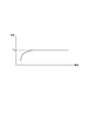
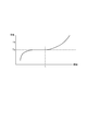
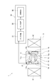
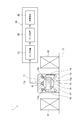
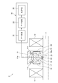
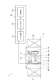
- 1 is a schematic diagram of an abnormality diagnosis system according to a first embodiment. It is a graph which shows the relationship between the detection temperature of a sensor, and time. It is a graph which shows the relationship between the detection temperature of a sensor, and time when abnormality has generate
- the abnormality diagnosis system 1 of the present embodiment includes a rolling bearing (deep groove ball bearing) 10, a single sensor 21 installed in the rolling bearing 10, and a signal output from the sensor 21.
- An abnormality diagnosis device 30 that diagnoses an abnormality of the rolling bearing 10 and various devices (for example, the motor 41 and the pump 42) is provided.
- the rolling bearing 10 includes an outer ring 11 having an outer ring raceway surface 11a on an inner peripheral surface (a race ring which is a fixed ring), an inner ring 13 having an inner ring raceway surface 13a on an outer peripheral surface (a race ring being a rotating ring), and an outer ring raceway.
- a plurality of balls 15 that are rotatably arranged between the surface 11a and the inner ring raceway surface 13a, a cage 17 that holds the plurality of balls 15 so as to roll, and both axial sides of the inner peripheral surface of the outer ring 11 And a pair of seal members 19 fixed to each other.
- the rolling bearing 10 includes a plurality of constituent members such as the outer ring 11, the inner ring 13, the ball 15, the cage 17, and the seal member 19.
- the inner ring 13 is a rotating wheel that is externally fixed to the shaft 3 and rotates together with the shaft 3.
- a motor 41 (device) is fixed to the shaft 3 on one axial end side (left side in the figure) of the rolling bearing 10, and the shaft 3 is rotationally driven by a rotor (not shown) of the motor 41.
- a pump 42 (device) is fixed to the shaft 3 on the other axial end side (right side in the drawing) of the rolling bearing 10, and the driving force of the motor 41 is transmitted to the pump 42 via the shaft 3. .
- the outer ring 11 is a fixed ring that is fitted and fixed to a housing (not shown) and does not rotate.
- a pair of seal grooves 11b for fixing a pair of seal members 19 are formed on the inner peripheral surface of the outer ring 11 on both sides in the axial direction of the outer ring raceway surface 11a.
- the pair of seal members 19 is a non-contact type that extends in the radial direction and faces the outer peripheral surface of the inner ring 13 via a gap. As a result, the pair of seal members 19 seals the space between the outer ring 11 and the inner ring 13 and prevents foreign matter from entering the bearing.
- a sensor 21 for detecting a surrounding signal is embedded and installed.
- the sensor 21 in the present embodiment is a temperature sensor 21 that is installed in the central portion in the axial direction near the outer peripheral surface of the outer ring 11.
- the temperature detected by the temperature sensor 21 is affected by the heat generated by the rolling bearing 10, the motor 41, and the pump 42.
- the temperature sensor 21 outputs the detected temperature and transmits it to the abnormality diagnosis device 30.
- the abnormality diagnosis device 30 is constituted by, for example, a microcomputer, and each unit such as the data collection unit 31 executes the following processes by executing a program recorded and held in the microcomputer. become.
- the data collection unit 31 of the abnormality diagnosis apparatus 30 collects output data from the temperature sensor 21.
- the data processing unit 33 of the abnormality diagnosis apparatus 30 processes the collected output data and stores each output data.
- the state determination unit 35 of the abnormality diagnosis apparatus 30 includes the rolling bearing 10, the motor 41, and the pump 42. It is determined that at least one is in an abnormal state.
- the temperature increase curve obtained from the output value of the temperature sensor 21 rises for a while after the rolling bearing 10, the motor 41, and the pump 42 are started to operate.
- the temperature reaches the rated temperature Ta the heat generated by the rolling bearing 10, the motor 41, and the pump 42 balances with the heat that escapes to the surroundings, resulting in a steady state.
- the pump 42 abnormally generates heat due to some factor.
- the output value of the temperature sensor 21 increases and exceeds a predetermined threshold value Tb.
- the output value of the temperature sensor 21 increases or the output value exceeds the threshold value Tb, so that at least one of the rolling bearing 10, the motor 41, and the pump 42 is in an abnormal state. It is determined that
- the abnormality diagnosis system 1 of the present embodiment it is possible to efficiently perform abnormality diagnosis of the rolling bearing 10 and abnormality diagnosis of the devices (the motor 41 and the pump 42) arranged around the rolling bearing 10. It is.
- the cost of the product can be reduced, and the handling of the sensor output wiring and the power supply wiring is simplified and the handling is improved. it can.
- the installation position of the sensor 21 may be changed as appropriate so as to be in a position or phase suitable for an object for which an abnormality is to be detected.
- the sensor 21 may be arranged in the vicinity of one end portion in the axial direction of the outer ring 11 to improve the sensitivity to the abnormality of the motor 41, thereby providing a sensor arrangement suitable for detecting the abnormality of the motor 41.
- the sensor 21 may be arranged near the other end in the axial direction of the outer ring 11 to improve the sensitivity to the abnormality of the pump 42, thereby providing a sensor arrangement suitable for detecting the abnormality of the pump 42.
- the sensor 21 is arranged in the vicinity of the outer ring raceway surface 11a of the outer ring 11 to improve the sensitivity to the abnormality of the rolling bearing 10, so that the sensor arrangement suitable for detecting the abnormality of the rolling bearing 10 can be obtained. Good.
- near the surface or “near the end” means a position that coincides with the surface or the end surface, or slightly enters the inside of the member from the surface or the end surface. It means position.
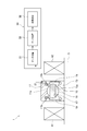
- the rolling bearing 10 of the present embodiment has the same configuration as that of the first embodiment except that the sensor 21 is disposed on the inner ring 13 from the configuration of the first embodiment in which the sensor 21 is disposed on the outer ring 11. It is. Therefore, the same code
- the abnormality diagnosis system 2 of the present embodiment includes a rolling bearing 10, a single sensor 21 installed on the inner ring 13 (the bearing ring that is a rotating ring) of the rolling bearing 10, and the sensor 21. And an abnormality diagnosis device 30 for diagnosing abnormalities in the rolling bearing 10 and various devices (for example, the motor 41 and the pump 42) based on the signal output from the motor.
- the inner ring 13 is embedded with a sensor 21 that detects ambient signals.
- the sensor 21 in the present embodiment is a temperature sensor 21 that is installed in the central portion in the axial direction near the inner peripheral surface of the inner ring 13. The temperature detected by the temperature sensor 21 is affected by the heat generated by the rolling bearing 10, the motor 41, and the pump 42.
- the temperature sensor 21 outputs the detected temperature and transmits it to the abnormality diagnosis device 30.
- the abnormality diagnosis device 30 is configured by, for example, a microcomputer, and by executing a program recorded and held in the microcomputer, each unit such as the data collection unit 31 is the same as that in the first embodiment described above. Each process is executed.
- the abnormality diagnosis system 2 of the present embodiment it is possible to efficiently perform abnormality diagnosis of the rolling bearing 10 and abnormality diagnosis of the devices (the motor 41 and the pump 42) arranged around the rolling bearing 10. It is.
- the cost of the product can be reduced, and the handling of the sensor output wiring and the power supply wiring is simplified and the handling is improved. it can.
- the installation position of the sensor 21 may be changed as appropriate so as to be in a position or phase suitable for an object for which an abnormality is to be detected.
- the sensor 21 may be arranged in the vicinity of one end portion in the axial direction of the inner ring 13 to improve the sensitivity to the abnormality of the motor 41, thereby providing a sensor arrangement suitable for detecting the abnormality of the motor 41.
- the sensor 21 may be arranged in the vicinity of the other end in the axial direction of the inner ring 13 to improve the sensitivity to the abnormality of the pump 42, thereby providing a sensor arrangement suitable for detecting the abnormality of the pump 42.
- the sensor 21 is arranged in the vicinity of the inner ring raceway surface 13a of the inner ring 13 to improve the sensitivity to the abnormality of the rolling bearing 10, so that the sensor arrangement suitable for detecting the abnormality of the rolling bearing 10 can be obtained. Good.
- the installation location of the sensor 21 is not limited to the outer ring 11 or the inner ring 13 as long as it is a constituent member of the rolling bearing 10, and may be, for example, the cage 17 or the seal member 19.
- the type of sensor 21 to be installed is not limited as long as it is a sensor that can monitor the state of the rolling bearing 10 and the devices (for example, the motor 41 and the pump 42) arranged around the rolling bearing 10, for example, a vibration sensor.
- a load sensor may be employed.
- a sensor when a sensor is installed on the inner ring 13 that is a rotating wheel, heat, vibration, load, etc. are easily transmitted from the shaft 3 or the like. Compared to the case where a sensor is installed, the behavior can be captured quickly.
- the signal transmission method from the sensor to the data collection unit 31 of the abnormality diagnosis device 30 may employ any method regardless of wired or wireless.
- the abnormality diagnosis device 30 determines an abnormality in the rolling bearing 10, the motor 41, or the pump 42, it can notify the host system to automatically stop the mechanical equipment, or display an alarm or screen display to the worker and the administrator. It is also possible to warn with etc.
- the device disposed around the rolling bearing 10 is not limited to the motor 41 and the pump 42 described above, and any device can be employed.
- rolling bearing 10 has illustrated the radial rolling bearing, this invention is not restricted to this, It can apply also to another kind of rolling bearing.
- An example of a configuration in which the present invention is applied to another type of rolling bearing is shown below.
- FIG. 11 is a cross-sectional view of the angular ball bearing 10A on which the sensor 21 is arranged.
- the angular ball bearing 10 ⁇ / b> A in the illustrated example includes an outer ring 11, an inner ring 13, a plurality of balls 15, and a cage 17 that holds the plurality of balls 15 so as to be able to roll.
- the sensor 21 is disposed at the axially central portion P ⁇ b> 1 near the outer peripheral surface of the outer ring 11.
- the senor 21 is disposed at a position P2 near one end in the axial direction near the outer peripheral surface of the outer ring 11 or near the outer peripheral surface of the outer ring 11 in the angular ball bearing 10A. May be a position P3 in the vicinity of the other end in the axial direction, and a position P4 in the vicinity of the outer ring raceway surface 11a of the outer ring 11. Further, the sensor 21 is disposed at the axial center P5 near the inner peripheral surface of the inner ring 13, the position P6 near one axial end near the inner peripheral surface of the inner ring 13, and the axial direction near the inner peripheral surface of the inner ring 13. The position P7 in the vicinity of the other end and the position P8 in the vicinity of the inner ring raceway surface 13a of the inner ring 13 may be used.
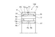
- FIG. 12A is a cross-sectional view of the cylindrical roller bearing 10B in which the sensor 21 is disposed
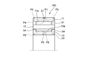
- FIG. 12B is a cross-sectional view of the cylindrical roller bearing 10C in which the sensor 21 is disposed.
- Cylindrical roller bearings 10B and 10C each have an outer ring 11, an inner ring 13, a plurality of rollers 51, and a retainer 17 that holds the plurality of rollers 51 in a rollable manner.
- a cylindrical roller bearing 10 ⁇ / b> B shown in FIG. 12A is provided with flange portions 53, 53 protruding radially inward at both axial end portions on the inner peripheral surface of the outer ring 11.
- the sensor 21 is disposed in the central portion P ⁇ b> 1 in the axial direction near the outer peripheral surface of the outer ring 11. Also in the case of this configuration, the arrangement location of the sensor 21 is not limited to the above example, and may be any of P1 to P8.
- FIG. 13 is a cross-sectional view of the tapered roller bearing 10D in which the sensor 21 is disposed.
- the tapered roller bearing 10 ⁇ / b> D includes an outer ring 11, an inner ring 13, a plurality of tapered rollers 55, and a cage 17 that holds the plurality of tapered rollers 55 in a rollable manner.
- the sensor 21 is disposed at the axially central portion P ⁇ b> 1 near the outer peripheral surface of the outer ring 11. Also in the case of this configuration, the arrangement location of the sensor 21 is not limited to the above example, and may be any of P1 to P8.
- FIG. 14 is a cross-sectional view of the self-aligning roller bearing 10E in which the sensor 21 is arranged.
- the self-aligning roller bearing 10E includes an outer ring 11, an inner ring 13, a plurality of rollers 57 arranged in two rows, and a cage 17 that holds the plurality of rollers in a freely rolling manner.
- the sensor 21 is disposed in the axially central portion P ⁇ b> 1 near the outer peripheral surface of the outer ring 11. Also in the case of this configuration, the arrangement location of the sensor 21 is not limited to the above example, and may be any of P1 to P8.
- Each bearing shown in FIGS. 11 to 14 includes an outer ring 11, an inner ring 13, a rolling element (ball 15, cylindrical roller 51, tapered roller 55, roller 57), a cage 17, and a seal member as a constituent member.
- the sensor 21 may be disposed on any one of these constituent members.
- the rotating wheel may be the outer ring 11 or the inner ring 13. Regardless of the configuration, the same effects as those of the first and second embodiments described above can be obtained.
Landscapes
- Engineering & Computer Science (AREA)
- General Engineering & Computer Science (AREA)
- Mechanical Engineering (AREA)
- Rolling Contact Bearings (AREA)
- Testing Of Devices, Machine Parts, Or Other Structures Thereof (AREA)
Abstract
Description
(1) 複数の構成部材からなる軸受と、
前記構成部材に設置され、周囲の信号を検出する一個のセンサと、
前記センサからの出力される信号に基づき、前記軸受の異常、及び前記軸受の周囲に配置された装置の異常を診断する異常診断装置と、
を備える、異常診断システム。
(2) 前記異常診断装置は、前記センサの出力値が上昇し又は所定の閾値を超えた場合に、前記軸受又は前記装置が異常であると判定する、(1)に記載の異常診断システム。
(3) 前記センサは、前記軸受の軌道輪の軸方向端部近傍に設置される、ことを特徴とする(1)又は(2)に記載の異常診断システム。
(4) 前記センサは、前記軸受の軌道輪の軌道面近傍に設置される、ことを特徴とする(1)又は(2)に記載の異常診断システム。
(5) 前記センサは温度センサである、(1)~(4)の何れか1つに記載の異常診断システム。
(6) 前記センサは振動センサである、(1)~(4)の何れか1つに記載の異常診断システム。
(7) 前記センサは荷重センサである、(1)~(4)の何れか1つに記載の異常診断システム。
(8) 前記センサは前記軸受の固定輪に設置される、(1)~(7)の何れか1つに記載の異常診断システム。
(9) 前記センサは前記軸受の回転輪に設置される、(1)~(7)の何れか1つに記載の異常診断システム。
図1に示すように、本実施形態の異常診断システム1は、転がり軸受(深溝玉軸受)10と、転がり軸受10に設置される一つのみのセンサ21と、センサ21から出力される信号に基づいて、転がり軸受10及び各種装置(例えばモータ41やポンプ42)の異常を診断する異常診断装置30と、を備える。
次に、センサ21が内輪13に配置された転がり軸受(深溝玉軸受)10を備える異常診断システム2を説明する。本実施形態の転がり軸受10は、外輪11にセンサ21が配置された前述の第1実施形態の構成から、内輪13にセンサ21を配置したこと以外は、前述の第1実施形態と同様の構成である。そのため、共通する部材に対しては、同一の符号を付与することで、その説明を簡単化、又は省略する。
10 軸受
11 外輪(構成部材、軌道輪)
13 内輪(構成部材、軌道輪)
15 玉(構成部材)
17 保持器(構成部材)
19 シール部材(構成部材)
21 温度センサ
30 異常診断装置
31 データ収集部
33 データ処理部
35 状態判定部
41 モータ(装置)
42 ポンプ(装置)
51 円筒ころ(構成部材)
55 円すいころ(構成部材)
57 ころ(構成部材)
Claims (9)
- 複数の構成部材からなる軸受と、
前記構成部材に設置され、周囲の信号を検出する一個のセンサと、
前記センサからの出力される信号に基づき、前記軸受の異常、及び前記軸受の周囲に配置された装置の異常を診断する異常診断装置と、
を備える、異常診断システム。 - 前記異常診断装置は、前記センサの出力値が上昇し又は所定の閾値を超えた場合に、前記軸受又は前記装置が異常であると判定する、請求項1に記載の異常診断システム。
- 前記センサは、前記軸受の軌道輪の軸方向端部近傍に設置される、ことを特徴とする請求項1又は2に記載の異常診断システム。
- 前記センサは、前記軸受の軌道輪の軌道面近傍に設置される、ことを特徴とする請求項1又は2に記載の異常診断システム。
- 前記センサは温度センサである、請求項1~4の何れか1項に記載の異常診断システム。
- 前記センサは振動センサである、請求項1~4の何れか1項に記載の異常診断システム。
- 前記センサは荷重センサである、請求項1~4の何れか1項に記載の異常診断システム。
- 前記センサは前記軸受の固定輪に設置される、請求項1~7の何れか1項に記載の異常診断システム。
- 前記センサは前記軸受の回転輪に設置される、請求項1~7の何れか1項に記載の異常診断システム。
Priority Applications (4)
| Application Number | Priority Date | Filing Date | Title |
|---|---|---|---|
| EP16786598.9A EP3290895A4 (en) | 2015-04-30 | 2016-04-28 | Abnormality diagnosis system |
| US15/554,505 US20180038413A1 (en) | 2015-04-30 | 2016-04-28 | Abnormality diagnosis system |
| CN201680025858.0A CN107532969A (zh) | 2015-04-30 | 2016-04-28 | 异常诊断系统 |
| JP2017515631A JPWO2016175322A1 (ja) | 2015-04-30 | 2016-04-28 | 異常診断システム |
Applications Claiming Priority (4)
| Application Number | Priority Date | Filing Date | Title |
|---|---|---|---|
| JP2015-092673 | 2015-04-30 | ||
| JP2015-092672 | 2015-04-30 | ||
| JP2015092673 | 2015-04-30 | ||
| JP2015092672 | 2015-04-30 |
Publications (1)
| Publication Number | Publication Date |
|---|---|
| WO2016175322A1 true WO2016175322A1 (ja) | 2016-11-03 |
Family
ID=57198586
Family Applications (1)
| Application Number | Title | Priority Date | Filing Date |
|---|---|---|---|
| PCT/JP2016/063483 Ceased WO2016175322A1 (ja) | 2015-04-30 | 2016-04-28 | 異常診断システム |
Country Status (5)
| Country | Link |
|---|---|
| US (1) | US20180038413A1 (ja) |
| EP (1) | EP3290895A4 (ja) |
| JP (1) | JPWO2016175322A1 (ja) |
| CN (1) | CN107532969A (ja) |
| WO (1) | WO2016175322A1 (ja) |
Cited By (6)
| Publication number | Priority date | Publication date | Assignee | Title |
|---|---|---|---|---|
| DE102017122089A1 (de) * | 2017-09-25 | 2019-03-28 | Schaeffler Technologies AG & Co. KG | Überwachungsanordnung und Verfahren zur Überwachung einer Maschine |
| DE102018101508A1 (de) * | 2018-01-24 | 2019-07-25 | Schaeffler Technologies AG & Co. KG | Lager und Verfahren zum Herstellen eines Lagers |
| JP6556398B1 (ja) * | 2018-03-26 | 2019-08-07 | 三菱電機株式会社 | 診断装置および閾値作成方法 |
| JP2019138464A (ja) * | 2018-02-13 | 2019-08-22 | Ntn株式会社 | 軸受装置およびスピンドル装置 |
| US20200007975A1 (en) * | 2017-03-17 | 2020-01-02 | Telefonaktiebolaget Lm Ericsson (Publ) | Method and appartus for adaptive audio signal alteration |
| JP2022144461A (ja) * | 2021-03-19 | 2022-10-03 | Ntn株式会社 | 軸受異常診断システム |
Families Citing this family (8)
| Publication number | Priority date | Publication date | Assignee | Title |
|---|---|---|---|---|
| US10260991B2 (en) * | 2015-02-19 | 2019-04-16 | Nsk Ltd. | Abnormality diagnosis system |
| DK3208571T3 (en) * | 2016-02-18 | 2019-03-04 | Siemens Ag | Device for measuring bearing |
| US10267358B2 (en) * | 2016-06-06 | 2019-04-23 | Bauer Equipment America, Inc. | Drill drive for a drilling rig |
| JP6967495B2 (ja) * | 2018-09-03 | 2021-11-17 | Ntn株式会社 | 軸受装置 |
| DE102018222421A1 (de) * | 2018-12-20 | 2020-06-25 | CEROBEAR GmbH | Wälzlager |
| EP3757539A1 (en) * | 2019-06-26 | 2020-12-30 | Siemens Aktiengesellschaft | System, apparatus and method of determining condition of a bearing |
| DE102021211493A1 (de) * | 2021-10-12 | 2023-04-13 | Aktiebolaget Skf | Vorrichtung und Verfahren zum Abschätzen einer Last in einem Lager |
| CN116123210A (zh) * | 2023-01-17 | 2023-05-16 | 中国航发哈尔滨轴承有限公司 | 一种外圈冷却结构滚道测温双半内圈角接触球轴承 |
Citations (3)
| Publication number | Priority date | Publication date | Assignee | Title |
|---|---|---|---|---|
| JP2002054637A (ja) * | 2000-03-30 | 2002-02-20 | Nsk Ltd | 転動装置 |
| JP2012008030A (ja) * | 2010-06-25 | 2012-01-12 | Toshiba Plant Systems & Services Corp | 回転機軸受診断装置 |
| JP2014145438A (ja) * | 2013-01-30 | 2014-08-14 | Nsk Ltd | 軸受回転状態計測監視装置 |
Family Cites Families (11)
| Publication number | Priority date | Publication date | Assignee | Title |
|---|---|---|---|---|
| JPS61228120A (ja) * | 1985-04-03 | 1986-10-11 | Koyo Seiko Co Ltd | 異常検出手段を備えた軸受装置 |
| GB2250785A (en) * | 1990-12-12 | 1992-06-17 | Huwood Ltd | Alarm system for bearings. |
| US6529135B1 (en) * | 1999-10-12 | 2003-03-04 | Csi Technology, Inc. | Integrated electric motor monitor |
| JP2005024441A (ja) * | 2003-07-04 | 2005-01-27 | Ntn Corp | Icタグ・センサ付き軸受の異常検査システム |
| JP5607285B2 (ja) * | 2006-06-23 | 2014-10-15 | 日本精工株式会社 | 軸受装置 |
| FR2908183B1 (fr) * | 2006-11-07 | 2009-01-23 | Univ Reims Champagne Ardenne | Dispositif et procede de surveillance de l'etat vibratoire d'une machine tournante |
| WO2008110201A1 (en) * | 2007-03-12 | 2008-09-18 | Aktiebolaget Skf | A sensorized bearing unit |
| JP2010162634A (ja) * | 2009-01-14 | 2010-07-29 | Jtekt Corp | 主軸装置 |
| DE102009022835B3 (de) * | 2009-05-27 | 2011-03-03 | Schaeffler Kg | Verfahren zur Überwachung des Zustands eines Fanglagers einer Maschine |
| JP5598082B2 (ja) * | 2010-05-17 | 2014-10-01 | 日本電気株式会社 | 異常判定装置、異常判定プログラムおよび異常判定方法 |
| US9011013B2 (en) * | 2011-05-09 | 2015-04-21 | Ntn Corporation | Sensor-equipped wheel bearing |
-
2016
- 2016-04-28 JP JP2017515631A patent/JPWO2016175322A1/ja active Pending
- 2016-04-28 US US15/554,505 patent/US20180038413A1/en not_active Abandoned
- 2016-04-28 EP EP16786598.9A patent/EP3290895A4/en active Pending
- 2016-04-28 WO PCT/JP2016/063483 patent/WO2016175322A1/ja not_active Ceased
- 2016-04-28 CN CN201680025858.0A patent/CN107532969A/zh active Pending
Patent Citations (3)
| Publication number | Priority date | Publication date | Assignee | Title |
|---|---|---|---|---|
| JP2002054637A (ja) * | 2000-03-30 | 2002-02-20 | Nsk Ltd | 転動装置 |
| JP2012008030A (ja) * | 2010-06-25 | 2012-01-12 | Toshiba Plant Systems & Services Corp | 回転機軸受診断装置 |
| JP2014145438A (ja) * | 2013-01-30 | 2014-08-14 | Nsk Ltd | 軸受回転状態計測監視装置 |
Non-Patent Citations (1)
| Title |
|---|
| See also references of EP3290895A4 * |
Cited By (9)
| Publication number | Priority date | Publication date | Assignee | Title |
|---|---|---|---|---|
| US20200007975A1 (en) * | 2017-03-17 | 2020-01-02 | Telefonaktiebolaget Lm Ericsson (Publ) | Method and appartus for adaptive audio signal alteration |
| DE102017122089A1 (de) * | 2017-09-25 | 2019-03-28 | Schaeffler Technologies AG & Co. KG | Überwachungsanordnung und Verfahren zur Überwachung einer Maschine |
| DE102018101508A1 (de) * | 2018-01-24 | 2019-07-25 | Schaeffler Technologies AG & Co. KG | Lager und Verfahren zum Herstellen eines Lagers |
| JP2019138464A (ja) * | 2018-02-13 | 2019-08-22 | Ntn株式会社 | 軸受装置およびスピンドル装置 |
| EP3754218A4 (en) * | 2018-02-13 | 2021-10-27 | NTN Corporation | BEARING DEVICE AND SPINDLE DEVICE |
| JP6556398B1 (ja) * | 2018-03-26 | 2019-08-07 | 三菱電機株式会社 | 診断装置および閾値作成方法 |
| WO2019186663A1 (ja) * | 2018-03-26 | 2019-10-03 | 三菱電機株式会社 | 診断装置および閾値作成方法 |
| JP2022144461A (ja) * | 2021-03-19 | 2022-10-03 | Ntn株式会社 | 軸受異常診断システム |
| JP7720158B2 (ja) | 2021-03-19 | 2025-08-07 | Ntn株式会社 | 軸受異常診断システム |
Also Published As
| Publication number | Publication date |
|---|---|
| EP3290895A4 (en) | 2018-05-09 |
| JPWO2016175322A1 (ja) | 2018-02-22 |
| EP3290895A1 (en) | 2018-03-07 |
| CN107532969A (zh) | 2018-01-02 |
| US20180038413A1 (en) | 2018-02-08 |
Similar Documents
| Publication | Publication Date | Title |
|---|---|---|
| JPWO2016175322A1 (ja) | 異常診断システム | |
| JP6308922B2 (ja) | 転がり軸受の異常診断装置、風力発電装置、及び転がり軸受の異常診断方法 | |
| US9689777B2 (en) | Fault detection for bearings | |
| CN104917333B (zh) | 旋转机械、轴承以及制造旋转机械的方法 | |
| JP4581693B2 (ja) | 異常診断装置 | |
| US10260991B2 (en) | Abnormality diagnosis system | |
| JP2006077938A (ja) | 異常診断装置 | |
| US9976933B2 (en) | Bearing monitoring system for an air cycle machine and method of monitoring | |
| JP6657256B2 (ja) | 送り軸の異常診断方法及び異常診断装置 | |
| CN111670311B (zh) | 轴承装置和主轴装置 | |
| JP2005345277A (ja) | 監視装置及び監視方法 | |
| WO2019221251A1 (ja) | 軸受の状態監視方法及び状態監視装置 | |
| JP2017044312A (ja) | センサ付き軸受及び状態監視システム | |
| US11802812B2 (en) | Device for monitoring the degradation of rolling bearings | |
| JP2017003555A (ja) | センサユニット、センサ付き軸受及び異常診断システム | |
| JP7351142B2 (ja) | 転がり軸受の状態監視方法及び状態監視装置 | |
| JP7696851B2 (ja) | 転がり軸受の異常検出装置及び異常検出方法 | |
| JP2007333195A (ja) | ボールねじ装置およびそのモニタ装置 | |
| WO2016199846A1 (ja) | センサユニット、センサ付き軸受及び異常診断システム | |
| CN115103966A (zh) | 轮毂单元轴承的状态判定装置、轮毂单元轴承的状态判定方法、程序及轮毂单元轴承 | |
| JP6953747B2 (ja) | 転がり軸受の状態監視装置 | |
| JP2018048668A (ja) | 車輪用転がり軸受の異常検出方法及び異常検出装置 | |
| JP2021018106A (ja) | 軸受異常予知装置および軸受異常予知方法 | |
| JP2004218814A (ja) | 軸受装置 | |
| JP2014035337A (ja) | モータ診断装置、方法及びプログラム |
Legal Events
| Date | Code | Title | Description |
|---|---|---|---|
| 121 | Ep: the epo has been informed by wipo that ep was designated in this application |
Ref document number: 16786598 Country of ref document: EP Kind code of ref document: A1 |
|
| ENP | Entry into the national phase |
Ref document number: 2017515631 Country of ref document: JP Kind code of ref document: A |
|
| WWE | Wipo information: entry into national phase |
Ref document number: 15554505 Country of ref document: US |
|
| REEP | Request for entry into the european phase |
Ref document number: 2016786598 Country of ref document: EP |
|
| NENP | Non-entry into the national phase |
Ref country code: DE |