WO2016178262A1 - 電動パワーステアリング制御装置および電動パワーステアリング制御方法 - Google Patents
電動パワーステアリング制御装置および電動パワーステアリング制御方法 Download PDFInfo
- Publication number
- WO2016178262A1 WO2016178262A1 PCT/JP2015/063061 JP2015063061W WO2016178262A1 WO 2016178262 A1 WO2016178262 A1 WO 2016178262A1 JP 2015063061 W JP2015063061 W JP 2015063061W WO 2016178262 A1 WO2016178262 A1 WO 2016178262A1
- Authority
- WO
- WIPO (PCT)
- Prior art keywords
- axis current
- command value
- current command
- limit value
- value
- Prior art date
- Legal status (The legal status is an assumption and is not a legal conclusion. Google has not performed a legal analysis and makes no representation as to the accuracy of the status listed.)
- Ceased
Links
Images



Classifications
-
- H—ELECTRICITY
- H02—GENERATION; CONVERSION OR DISTRIBUTION OF ELECTRIC POWER
- H02P—CONTROL OR REGULATION OF ELECTRIC MOTORS, ELECTRIC GENERATORS OR DYNAMO-ELECTRIC CONVERTERS; CONTROLLING TRANSFORMERS, REACTORS OR CHOKE COILS
- H02P21/00—Arrangements or methods for the control of electric machines by vector control, e.g. by control of field orientation
- H02P21/22—Current control, e.g. using a current control loop
-
- B—PERFORMING OPERATIONS; TRANSPORTING
- B62—LAND VEHICLES FOR TRAVELLING OTHERWISE THAN ON RAILS
- B62D—MOTOR VEHICLES; TRAILERS
- B62D5/00—Power-assisted or power-driven steering
- B62D5/04—Power-assisted or power-driven steering electrical, e.g. using an electric servo-motor connected to, or forming part of, the steering gear
- B62D5/0457—Power-assisted or power-driven steering electrical, e.g. using an electric servo-motor connected to, or forming part of, the steering gear characterised by control features of the drive means as such
- B62D5/046—Controlling the motor
- B62D5/0463—Controlling the motor calculating assisting torque from the motor based on driver input
-
- B—PERFORMING OPERATIONS; TRANSPORTING
- B62—LAND VEHICLES FOR TRAVELLING OTHERWISE THAN ON RAILS
- B62D—MOTOR VEHICLES; TRAILERS
- B62D6/00—Arrangements for automatically controlling steering depending on driving conditions sensed and responded to, e.g. control circuits
- B62D6/02—Arrangements for automatically controlling steering depending on driving conditions sensed and responded to, e.g. control circuits responsive only to vehicle speed
-
- B—PERFORMING OPERATIONS; TRANSPORTING
- B62—LAND VEHICLES FOR TRAVELLING OTHERWISE THAN ON RAILS
- B62D—MOTOR VEHICLES; TRAILERS
- B62D6/00—Arrangements for automatically controlling steering depending on driving conditions sensed and responded to, e.g. control circuits
- B62D6/08—Arrangements for automatically controlling steering depending on driving conditions sensed and responded to, e.g. control circuits responsive only to driver input torque
- B62D6/10—Arrangements for automatically controlling steering depending on driving conditions sensed and responded to, e.g. control circuits responsive only to driver input torque characterised by means for sensing or determining torque
-
- H—ELECTRICITY
- H02—GENERATION; CONVERSION OR DISTRIBUTION OF ELECTRIC POWER
- H02P—CONTROL OR REGULATION OF ELECTRIC MOTORS, ELECTRIC GENERATORS OR DYNAMO-ELECTRIC CONVERTERS; CONTROLLING TRANSFORMERS, REACTORS OR CHOKE COILS
- H02P21/00—Arrangements or methods for the control of electric machines by vector control, e.g. by control of field orientation
- H02P21/0085—Arrangements or methods for the control of electric machines by vector control, e.g. by control of field orientation specially adapted for high speeds, e.g. above nominal speed
- H02P21/0089—Arrangements or methods for the control of electric machines by vector control, e.g. by control of field orientation specially adapted for high speeds, e.g. above nominal speed using field weakening
-
- H—ELECTRICITY
- H02—GENERATION; CONVERSION OR DISTRIBUTION OF ELECTRIC POWER
- H02P—CONTROL OR REGULATION OF ELECTRIC MOTORS, ELECTRIC GENERATORS OR DYNAMO-ELECTRIC CONVERTERS; CONTROLLING TRANSFORMERS, REACTORS OR CHOKE COILS
- H02P27/00—Arrangements or methods for the control of AC motors characterised by the kind of supply voltage
- H02P27/04—Arrangements or methods for the control of AC motors characterised by the kind of supply voltage using variable-frequency supply voltage, e.g. inverter or converter supply voltage
- H02P27/06—Arrangements or methods for the control of AC motors characterised by the kind of supply voltage using variable-frequency supply voltage, e.g. inverter or converter supply voltage using DC to AC converters or inverters
- H02P27/08—Arrangements or methods for the control of AC motors characterised by the kind of supply voltage using variable-frequency supply voltage, e.g. inverter or converter supply voltage using DC to AC converters or inverters with pulse width modulation
- H02P27/12—Arrangements or methods for the control of AC motors characterised by the kind of supply voltage using variable-frequency supply voltage, e.g. inverter or converter supply voltage using DC to AC converters or inverters with pulse width modulation pulsing by guiding the flux vector, current vector or voltage vector on a circle or a closed curve, e.g. for direct torque control
-
- H—ELECTRICITY
- H02—GENERATION; CONVERSION OR DISTRIBUTION OF ELECTRIC POWER
- H02P—CONTROL OR REGULATION OF ELECTRIC MOTORS, ELECTRIC GENERATORS OR DYNAMO-ELECTRIC CONVERTERS; CONTROLLING TRANSFORMERS, REACTORS OR CHOKE COILS
- H02P29/00—Arrangements for regulating or controlling electric motors, appropriate for both AC and DC motors
- H02P29/02—Providing protection against overload without automatic interruption of supply
- H02P29/032—Preventing damage to the motor, e.g. setting individual current limits for different drive conditions
-
- H—ELECTRICITY
- H02—GENERATION; CONVERSION OR DISTRIBUTION OF ELECTRIC POWER
- H02P—CONTROL OR REGULATION OF ELECTRIC MOTORS, ELECTRIC GENERATORS OR DYNAMO-ELECTRIC CONVERTERS; CONTROLLING TRANSFORMERS, REACTORS OR CHOKE COILS
- H02P29/00—Arrangements for regulating or controlling electric motors, appropriate for both AC and DC motors
- H02P29/60—Controlling or determining the temperature of the motor or of the drive
- H02P29/68—Controlling or determining the temperature of the motor or of the drive based on the temperature of a drive component or a semiconductor component
-
- B—PERFORMING OPERATIONS; TRANSPORTING
- B62—LAND VEHICLES FOR TRAVELLING OTHERWISE THAN ON RAILS
- B62D—MOTOR VEHICLES; TRAILERS
- B62D5/00—Power-assisted or power-driven steering
- B62D5/04—Power-assisted or power-driven steering electrical, e.g. using an electric servo-motor connected to, or forming part of, the steering gear
- B62D5/0457—Power-assisted or power-driven steering electrical, e.g. using an electric servo-motor connected to, or forming part of, the steering gear characterised by control features of the drive means as such
- B62D5/046—Controlling the motor
Definitions
- the present invention relates to an electric power steering control device and an electric power steering control method, and more particularly to current command value calculation for driving and controlling an AC motor that assists steering of a steering wheel.
- the command value of the assist torque to be output to the AC motor is set to the q-axis current value (hereinafter referred to as the q-axis current).
- a d-axis current value (hereinafter referred to as a d-axis current command value) by field weakening control of the AC motor.
- this conventional electric power steering control device sets the q-axis current command value for the purpose of improving the steering feeling when a predetermined condition is satisfied and the q-axis current command value needs to be limited.
- it has a function of limiting the d-axis current command value at the same rate as the limit of the q-axis current command value (see, for example, Patent Document 1).
- FIG. 5 is a diagram showing the relationship between the d-axis current command value with respect to the motor speed and the maximum assist torque with respect to the motor speed in the conventional electric power steering control device.
- the conventional electric power steering control device performs field weakening control. Specifically, the conventional electric power steering control device outputs a d-axis current command value based on the motor rotational speed, and performs control to alleviate a decrease in the maximum value of the assist torque.
- the d-axis current command value is also limited at the same rate as the limitation. For this reason, when the steering wheel is operated steeply, the d-axis current command value is insufficient, and there is a problem that the followability is lowered.
- the present invention has been made to solve the above-described problems.
- current limitation is applied to an AC motor that assists steering of a steering wheel in a high-speed steering range
- the present invention is more effective than conventional techniques. It is an object of the present invention to obtain an electric power steering control device and an electric power steering control method capable of improving followability.
- An electric power steering control device includes a main controller that controls a motor current for driving an AC motor for assisting steering of a steering wheel based on a d-axis current command value and a q-axis current command value.
- the main controller controls the dq conversion current command value.
- the d-axis current limit value is calculated with priority, and the d-axis current command value is clipped below the d-axis current limit value to obtain the d-axis current command value after the limit.
- a q-axis current limit value is calculated based on the calculated d-axis current limiter, the dq conversion current limit value, and the d-axis current command value after the limit calculated by the d-axis current limiter.
- the motor current is calculated based on the q-axis current limiter that calculates the restricted q-axis current command value by clipping below the limit value, and the d-axis current command value after restriction and the q-axis current command value after restriction. And an inverter controller to be controlled.
- the electric power steering control method is a main controller that controls a motor current for driving an AC motor for assisting steering of a steering wheel based on a d-axis current command value and a q-axis current command value.
- the main controller when the dq conversion current command value, which is the square root of the square sum of the d-axis current command value and the q-axis current command value, is limited, A first step of obtaining a dq conversion current limit value that is a limit value of the conversion current command value, and a second step of preferentially calculating the d-axis current limit value based on the dq conversion current limit value acquired in the first step And a third step of calculating the d-axis current command value after limitation by clipping the d-axis current command value to be equal to or less than the d-axis current limit value calculated in the second step, Based on the dq conversion current limit value obtained in step 4 and the limited d-axis current command value calculated in the third
- the d-axis current command value when the current limit is performed during steering of the steering wheel, the d-axis current command value is equal to or less than the d-axis current limit value regardless of the limit ratio of the q-axis current command value. Control is made so that output is possible, and the d-axis current command value is preferentially calculated over the q-axis current command value.
- FIG. 1 is an overall configuration diagram of an electric power steering control device according to Embodiment 1 of the present invention. It is a figure for demonstrating the current limiting method by the electric power steering control apparatus in Embodiment 1 of this invention. It is a figure for demonstrating the electric current limiting method by the electric power steering control apparatus in patent document 1.
- FIG. It is the flowchart which showed a series of processes of the electric power steering control method performed by ECU in Embodiment 1 of this invention. It is the figure which showed the relationship of the d-axis electric current command value with respect to the motor speed in the conventional electric power steering control apparatus, and the maximum value of the assist torque with respect to the motor speed.
- FIG. 1 is an overall configuration diagram of an electric power steering control device according to Embodiment 1 of the present invention. More specifically, the electric power steering control device shown in FIG. 1 includes a main controller 10 (hereinafter referred to as an ECU 10) mounted on a vehicle for controlling control, a motor 1 for assisting steering force of the steering wheel, A torque sensor 2 mounted near the steering wheel for detecting the steering torque, a vehicle speed sensor 3 for detecting the vehicle speed, a resolver sensor 4 for detecting the rotation angle of the motor 1, and a temperature sensor 5 for detecting the ambient temperature of the ECU 10 are provided. Yes.
- a main controller 10 hereinafter referred to as an ECU 10
- the electric power steering control device shown in FIG. 1 includes a main controller 10 (hereinafter referred to as an ECU 10) mounted on a vehicle for controlling control, a motor 1 for assisting steering force of the steering wheel, A torque sensor 2 mounted near the steering wheel for detecting the steering torque, a vehicle speed sensor 3 for detecting the vehicle speed, a
- the ECU 10 incorporating the CPU includes a q-axis current calculator 11, a motor rotation speed calculator 12, a d-axis current calculator 13, a dq conversion current limit value calculator 14, a d-axis current limiter 15, and a q-axis current limiter 16. , And an inverter controller 17.
- the q-axis current calculator 11 inputs the steering torque signal Trq detected by the torque sensor 2 and the vehicle speed signal Vs detected by the vehicle speed sensor, and sets the q-axis current command value Iq.
- the motor rotation number calculator 12 calculates a motor rotation number N per unit time from the rotation angle ⁇ of the motor 1 detected by the resolver sensor 4.
- the d-axis current calculator 13 calculates the d-axis current command from the q-axis current command value Iq set by the q-axis current calculator 11 and the motor rotational speed N calculated by the motor rotational speed calculator 12. Set the value Id.
- the dq conversion current limit value calculator 14 determines a dq conversion current limit value Idq_LIM that is a limit value of the motor current from the ambient temperature T detected by the temperature sensor 5.
- the d-axis current limiter 15 limits the d-axis current command value Id set by the d-axis current calculator 13 using the dq conversion current limit value Idq_LIM determined by the dq conversion current limit value calculator 14. Further, the q-axis current limiter 16 calculates a d-axis current command value Id ′ (hereinafter referred to as a post-limit d-axis current command value Id ′) after being limited by the d-axis current limiter 15 and a dq conversion current limit value calculation. The q-axis current command value Iq set by the q-axis current calculator 11 is limited using the dq conversion current limit value Idq_LIM determined by the calculator 14.
- the inverter controller 17 has a q-axis current command value Iq ′ after being restricted by the q-axis current limiter 16 (hereinafter referred to as a restricted q-axis current command value Iq ′), and after being restricted by the d-axis current limiter 15.
- a restricted q-axis current command value Iq ′ Three-phase currents Iu, Iv, and Iw are output from the d-axis current command value Id ′ and the rotation angle ⁇ of the motor 1 detected by the resolver sensor 4 to drive the motor 1.
- the d-axis current limiter 15 calculates the d-axis current limit value Id_LIM using the dq conversion current limit value Idq_LIM according to the following equation (1). Further, the d-axis current limiter 15 calculates the post-limit d-axis current command value Id ′ by limiting the d-axis current command value Id to the d-axis current limit value Id_LIM or less according to the following equation (2). .
- the q-axis current limiter 16 calculates the q-axis current limit value (Iq_LIM) using the post-limit d-axis current command value Id ′ and the dq conversion current limit value Idq_LIM according to the following equation (3). Further, the q-axis current limiter 16 calculates the post-limit q-axis current limit value Iq ′ by limiting the q-axis current command value Iq ′ to the q-axis current limit value Iq_LIM or less according to the following formula (4). To do.
- the ECU 10 calculates the current command value according to the following procedure.
- the d-axis current command value Id and the q-axis current command value Iq are subjected to some restriction, for example, overheat protection restriction, by the dq conversion current restriction value Idq_LIM, first, the above formula (1 ) And (2), the post-limit d-axis current command value Id ′ is calculated.
- the post-limit q-axis current command value Iq ′ is calculated according to the above formulas (3) and (4).
- the electric power steering control apparatus calculates the optimal post-limit q-axis current command value Iq ′ after calculating the optimal post-limit d-axis current command value Id ′. Is a technical feature. As a result, it is possible to obtain an electric power steering control device capable of realizing high followability.
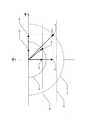
- FIG. 2 is a diagram for explaining a current limiting method by the electric power steering control device according to Embodiment 1 of the present invention.
- FIG. 3 is a diagram for explaining a current limiting method by the electric power steering control device in Patent Document 1.
- FIG. 2 is a diagram for explaining a current limiting method by the electric power steering control device according to Embodiment 1 of the present invention.
- FIG. 3 is a diagram for explaining a current limiting method by the electric power steering control device in Patent Document 1.
- FIG. 3 is a diagram for explaining a current limiting method by the electric power steering control device in Patent Document 1.
- FIG. 2 showing the current control method according to the first embodiment is a vector diagram of a motor current in which the horizontal axis is a q-axis current command value and the vertical axis is a d-axis current command value.
- Semicircle 22 dq conversion current limit value Idq_LIM is smaller than semicircle 21 due to current limitation.
- Semicircle and straight line 23 when limited to the value: Limit value when the d-axis current limit value Id_LIM is the rated value Id_MAX of the d-axis current command value.
- a combined vector 31 a combined vector when the qq current command value and the d axis converted current command value Idq * are combined, and the magnitude of the vector is equal to the dq converted current limit value by the semicircle 21
- D-axis vector 32 a vector indicating the restricted d-axis current command value Id ′ as a d-axis component corresponding to the combined vector 31
- q-axis vector 33 a limited as a q-axis component corresponding to the combined vector 31
- a combined vector 41 a combined vector when a qq current command value and a d axis converted current command value Idq * are combined, and the magnitude of the vector is equal to the dq converted current limit value by the semicircle 22
- D-axis vector 42 a vector indicating the restricted d-axis current command value Id ′ as the d-axis component corresponding to the combined vector 41
- q-axis vector 43 the limited as the q-axis component corresponding to the combined vector 41
- the d-axis current limit value Id_LIM decreases from the straight line 23 to the straight line 24 according to the above equation (1).
- the post-limit d-axis current command value Id ′ is calculated according to the above equation (2), and decreases from the vector 32 to the vector 42. That is, the post-limit d-axis current command value Id ′ is calculated with priority.
- the q-axis current limit value Iq_LIM is obtained by the above formula (3), and as a result, the post-limit q-axis current command value Iq ′ is calculated according to the above formula (4) and decreases from the vector 33 to the vector 43. . Finally, the current flowing in the motor 1 becomes a combined vector 41 of the vector 42 and the vector 43.
- FIG. 3 showing the current control method in Patent Document 1 is a motor current vector diagram in which the horizontal axis is the q-axis current command value and the vertical axis is the d-axis current command value, as in FIG. Yes, the respective symbols mean the following contents. Note that the same reference numerals as those in FIG. 2 mean the same contents, and a description thereof is omitted.
- a combined vector 51 a combined vector when the qq current command value and the d axis converted current command value Idq * are combined, and the magnitude of the vector is equal to the dq converted current limit value by the semicircle 22
- D-axis vector 52 a vector indicating the restricted d-axis current command value Id ′ as a d-axis component corresponding to the combined vector 51
- q-axis vector 53 a limited as a q-axis component corresponding to the combined vector 51
- the d-axis current command value and the q-axis are set such that the vector 51 corresponding to the limited dq-converted current command value becomes a dq-converted current limit value corresponding to the magnitude indicated by the semicircle 22.
- the current command value is decreased at the same rate, and the vectors 52 and 53 are calculated.
- the post-limit d-axis current command value and the post-limit q-axis current command value fall as vectors 52 and 53, respectively, and the combined current of the post-limit d-axis current command value and the post-limit q-axis current command value Becomes the vector 51.
- both the vector 41 and the vector 51 corresponding to the dq converted current command value which is a composite value of the limited d-axis current command value and the limited q-axis current command value.
- the point that is limited by the size of the semicircle 22 is the same.
- the vector 42 subjected to the current limitation according to the first embodiment performs the current limitation according to Patent Document 1. Since it is larger than the vector 52, a large amount of d-axis current can flow. As a result, the current limiting method according to the first embodiment can improve the trackability compared to the current limiting method according to Patent Document 1.
- FIG. 4 is a flowchart showing a series of processes of the electric power steering control method executed by the ECU 10 in the first embodiment of the present invention.
- step S401 the q-axis current command value Iq is calculated by the q-axis current calculator 11 and the d-axis current command value Id is calculated by the d-axis current calculator 13 in the same manner as in the prior art.
- step S402 the dq conversion current limit value calculator 14 calculates a dq conversion current limit value Idq_LIM.
- the dq conversion current limit value calculator 14 determines the dq conversion current limit value Idq_LIM, which is the limit value of the motor current, from the ambient temperature T detected by the temperature sensor 5.
- the dq conversion current limit value Idq_LIM is not necessarily limited to the case where it is calculated based on the temperature detection value by the temperature sensor 5.
- the ECU 10 can obtain from the outside or calculate based on other detection values as a value for applying a current limit to the AC motor that assists steering of the steering wheel. Applicable.
- step S403 the d-axis current limiter 15 calculates the d-axis current limit value Id_LIM using the above equation (1) based on the dq conversion current limit value Idq_LIM calculated in step S402. That is, the d-axis current limit value Id_LIM is calculated with priority over the q-axis current limit value Iq_LIM.
- step S404 the d-axis current limiter 15 uses the above equation (2) to set the d-axis current command value Id calculated in step S401 to be equal to or less than the d-axis current limit value Id_LIM calculated in step S403.
- the d-axis current command value Id ′ after the limitation is calculated by clipping to.
- step S405 the q-axis current limiter 16 calculates the upper limit based on the dq conversion current limit value Idq_LIM calculated in step S402 and the limited d-axis current command value Id ′ calculated in step S404.
- the q-axis current limit value Iq_LIM is calculated using Expression (3).
- step S406 the q-axis current limiter 16 uses the above equation (4) to set the q-axis current command value Iq calculated in step S401 to be equal to or less than the q-axis current limit value Iq_LIM calculated in step S405. , The q-axis current command value Iq ′ after the limitation is calculated.
- step S407 the inverter controller 17 uses the limited d-axis current command value Id ′ calculated in step S404 and the limited q-axis current command value Iq ′ calculated in step S406.
- the three-phase currents Iu, Iv, and Iw for driving the motor 1 are controlled.
- the restricted d-axis current command value Id ′ is determined with priority in steps S403 to S406, the restricted q-axis current command value is determined.
- Iq ′ is determined.
- the d-axis current command value when the current limit is performed while the steering wheel is being steered, the d-axis current command value is set to the d-axis current regardless of the limit ratio of the q-axis current command value. If it is below the current limit value, output is possible, and the d-axis current command value is preferentially calculated over the q-axis current command value. As a result, in the high rotation range of the AC motor, the d-axis current command value is not limited as compared with the prior art, and the followability can be improved to the maximum.
Landscapes
- Engineering & Computer Science (AREA)
- Power Engineering (AREA)
- Chemical & Material Sciences (AREA)
- Combustion & Propulsion (AREA)
- Transportation (AREA)
- Mechanical Engineering (AREA)
- Control Of Ac Motors In General (AREA)
- Steering Control In Accordance With Driving Conditions (AREA)
Abstract
Description
図5は、従来の電動パワーステアリング制御装置におけるモータ回転数に対するd軸電流指令値、およびモータ回転数に対するアシストトルクの最大値の関係を示した図である。モータの逆起電力が電源電圧を超える所定のモータ回転数N1以上では、アシストトルクの最大値が低下する問題がある。この問題に対して、従来の電動パワーステアリング制御装置は、弱め界磁制御を行っている。具体的には、従来の電動パワーステアリング制御装置は、モータ回転数に基づくd軸電流指令値を出力し、アシストトルクの最大値が低下することを緩和する制御を行っている。
図1は、本発明の実施の形態1における電動パワーステアリング制御装置の全体構成図である。より具体的には、この図1に示す電動パワーステアリング制御装置は、制御を司るために車両に装着された主制御器10(以下、ECU10と称す)、ハンドルの操舵力をアシストするモータ1、ハンドル付近に搭載され操舵トルクを検出するトルクセンサ2、車速を検出する車速センサ3、モータ1の回転角度を検出するレゾルバセンサ4、ECU10の雰囲気温度を検出する温度センサ5を備えて構成されている。


(手順1)dq変換電流制限値Idq_LIMにより、d軸電流指令値Idとq軸電流指令値Iqが、例えば過熱保護制限のように、なんらかの制限を受けた場合には、まず、上式(1)、(2)に従って、制限後d軸電流指令値Id’を算出する。
(手順2)次に、dq変換電流制限値Idq_LIMの範囲内で、上式(3)、(4)に従って、制限後q軸電流指令値Iq’を算出する。
・半円21:dq変換電流制限値Idq_LIMが、dq変換電流指令値の定格値Idq_MAXであるときの半円
・半円22:電流制限によりdq変換電流制限値Idq_LIMが、半円21よりも小さい値に制限されたときの半円
・直線23:d軸電流制限値Id_LIMが、d軸電流指令値の定格値Id_MAXであるときの制限値
・直線24:d軸電流制限値Id_LIMが、電流制限により、直線23よりも低下したときの制限値
・d軸ベクトル32:合成ベクトル31に対応するd軸成分としての、制限後d軸電流指令値Id’を示すベクトル
・q軸ベクトル33:合成ベクトル31に対応するq軸成分としての、制限後q軸電流指令値Iq’を示すベクトル
・d軸ベクトル42:合成ベクトル41に対応するd軸成分としての、制限後d軸電流指令値Id’を示すベクトル
・q軸ベクトル43:合成ベクトル41に対応するq軸成分としての、制限後q軸電流指令値Iq’を示すベクトル
・合成ベクトル51:q軸電流指令値とd軸電流指令値を合成したdq変換電流指令値Idq*であり、ベクトルの大きさが、半円22によるdq変換電流制限値に等しいときの合成ベクトル
・d軸ベクトル52:合成ベクトル51に対応するd軸成分としての、制限後d軸電流指令値Id’を示すベクトル
・q軸ベクトル53:合成ベクトル51に対応するq軸成分としての、制限後q軸電流指令値Iq’を示すベクトル
Claims (5)
- ステアリングホイールの操舵を補助する交流モータを駆動させるためのモータ電流を、d軸電流指令値とq軸電流指令値に基づいて制御する主制御器を備えた電動パワーステアリング制御装置において、
前記主制御器は、前記d軸電流指令値と前記q軸電流指令値の二乗和の平方根であるdq変換電流指令値に制限がかかった場合に、
前記dq変換電流指令値の制限値であるdq変換電流制限値に基づいてd軸電流制限値を優先して算出し、前記d軸電流指令値を前記d軸電流制限値以下にクリップすることで制限後のd軸電流指令値を算出するd軸電流制限器と、
前記dq変換電流制限値と前記d軸電流制限器によって算出された前記制限後のd軸電流指令値とに基づいてq軸電流制限値を算出し、前記q軸電流指令値を前記q軸電流制限値以下にクリップすることで制限後のq軸電流指令値を算出するq軸電流制限器と、
前記制限後のd軸電流指令値と前記制限後のq軸電流指令値に基づいて前記モータ電流を制御するインバータ制御器と
を備える電動パワーステアリング制御装置。 - 前記d軸電流制限器は、
d軸電流定格値をId_MAX、
dq変換電流定格値をIdq_MAX、
前記dq変換電流制限値をIdq_LIM、
前記d軸電流制限値をId_LIM、
とした場合に、前記d軸電流制限値を下式
Id_LIM=Id_MAX
×(Idq_LIM/Idq_MAX)
を用いて算出する
請求項1に記載の電動パワーステアリング制御装置。 - 前記q軸電流制限器は、
前記d軸電流制限器で算出された前記制限後のd軸電流指令値をId’
前記dq変換電流制限値をIdq_LIM、
前記q軸電流制限値をIq_LIM、
とした場合に、前記q軸電流制限値を下式
Iq_LIM=√{(Idq_LIM)2-(Id’)2}
を用いて算出する
請求項1または2に記載の電動パワーステアリング制御装置。 - 前記主制御器は、
前記主制御器の雰囲気温度を計測する温度センサと、
前記温度センサにより計測された前記雰囲気温度に基づいて、過熱保護を図るための前記dq変換電流制限値を決定する制限値演算器と
をさらに備える請求項1から3のいずれか1項に記載の電動パワーステアリング制御装置。 - ステアリングホイールの操舵を補助する交流モータを駆動させるためのモータ電流を、d軸電流指令値とq軸電流指令値に基づいて制御する主制御器によって実行される電動パワーステアリング制御方法であって、
前記d軸電流指令値と前記q軸電流指令値の二乗和の平方根であるdq変換電流指令値に制限がかかった場合に、前記主制御器において、
前記dq変換電流指令値の制限値であるdq変換電流制限値を取得する第1ステップと、
前記第1ステップにより取得した前記dq変換電流制限値に基づいてd軸電流制限値を優先して算出する第2ステップと、
前記d軸電流指令値を、前記第2ステップで算出した前記d軸電流制限値以下にクリップすることで制限後のd軸電流指令値を算出する第3ステップと、
前記第1ステップで取得した前記dq変換電流制限値と、前記第3ステップで算出した前記制限後のd軸電流指令値とに基づいて、q軸電流制限値を算出する第4ステップと、
前記q軸電流指令値を、前記第4ステップで算出した前記q軸電流制限値以下にクリップすることで制限後のq軸電流指令値を算出する第5ステップと、
前記第3ステップで算出した前記制限後のd軸電流指令値と、前記第5ステップで算出した前記制限後のq軸電流指令値とに基づいて、前記モータ電流を制御する第6ステップと
を有する電動パワーステアリング制御方法。
Priority Applications (5)
| Application Number | Priority Date | Filing Date | Title |
|---|---|---|---|
| PCT/JP2015/063061 WO2016178262A1 (ja) | 2015-05-01 | 2015-05-01 | 電動パワーステアリング制御装置および電動パワーステアリング制御方法 |
| JP2017516229A JP6355835B2 (ja) | 2015-05-01 | 2015-05-01 | 電動パワーステアリング制御装置および電動パワーステアリング制御方法 |
| US15/569,150 US10536102B2 (en) | 2015-05-01 | 2015-05-01 | Electric power steering control apparatus and electric power steering control method |
| EP15891269.1A EP3290296B1 (en) | 2015-05-01 | 2015-05-01 | Electric power steering control device and electric power steering control method |
| CN201580079172.5A CN107531277B (zh) | 2015-05-01 | 2015-05-01 | 电动助力转向控制装置及电动助力转向控制方法 |
Applications Claiming Priority (1)
| Application Number | Priority Date | Filing Date | Title |
|---|---|---|---|
| PCT/JP2015/063061 WO2016178262A1 (ja) | 2015-05-01 | 2015-05-01 | 電動パワーステアリング制御装置および電動パワーステアリング制御方法 |
Publications (1)
| Publication Number | Publication Date |
|---|---|
| WO2016178262A1 true WO2016178262A1 (ja) | 2016-11-10 |
Family
ID=57218537
Family Applications (1)
| Application Number | Title | Priority Date | Filing Date |
|---|---|---|---|
| PCT/JP2015/063061 Ceased WO2016178262A1 (ja) | 2015-05-01 | 2015-05-01 | 電動パワーステアリング制御装置および電動パワーステアリング制御方法 |
Country Status (5)
| Country | Link |
|---|---|
| US (1) | US10536102B2 (ja) |
| EP (1) | EP3290296B1 (ja) |
| JP (1) | JP6355835B2 (ja) |
| CN (1) | CN107531277B (ja) |
| WO (1) | WO2016178262A1 (ja) |
Cited By (1)
| Publication number | Priority date | Publication date | Assignee | Title |
|---|---|---|---|---|
| EP3576298A4 (en) * | 2017-03-01 | 2020-01-08 | Panasonic Intellectual Property Management Co., Ltd. | ROBOT CONTROL METHOD |
Families Citing this family (10)
| Publication number | Priority date | Publication date | Assignee | Title |
|---|---|---|---|---|
| JP6445937B2 (ja) * | 2015-07-03 | 2018-12-26 | 日立オートモティブシステムズ株式会社 | 電動パワーステアリング装置 |
| JP6737222B2 (ja) * | 2017-04-14 | 2020-08-05 | 株式会社デンソー | ステアリング制御装置 |
| JP7155691B2 (ja) * | 2018-07-13 | 2022-10-19 | 株式会社デンソー | 回転電機の制御装置 |
| JP7029368B2 (ja) * | 2018-09-06 | 2022-03-03 | 株式会社日立産機システム | 同期電動機制御装置 |
| JP6677362B1 (ja) * | 2018-10-19 | 2020-04-08 | 日本精工株式会社 | モータ制御装置、電動アクチュエータ製品及び電動パワーステアリング装置 |
| US10972033B2 (en) | 2018-10-19 | 2021-04-06 | Nsk Ltd. | Motor control device, electrically driven actuator product, and electrically driven power steering device |
| US11101764B2 (en) * | 2019-11-14 | 2021-08-24 | Steering Solutions Ip Holding Corporation | Dynamic control of source current in electric motor drive systems |
| JP7317250B2 (ja) * | 2020-11-30 | 2023-07-28 | 三菱電機株式会社 | 回転電機の制御装置及び電動パワーステアリング装置 |
| US20250202394A1 (en) * | 2022-03-16 | 2025-06-19 | Mitsubishi Electric Corporation | Control apparatus for ac rotating machine, and electric power steering apparatus |
| US20250187651A1 (en) * | 2022-03-16 | 2025-06-12 | Mitsubishi Electric Corporation | Control device for ac rotating machine and electric power steering device |
Citations (8)
| Publication number | Priority date | Publication date | Assignee | Title |
|---|---|---|---|---|
| JP2003052199A (ja) * | 2001-08-07 | 2003-02-21 | Fanuc Ltd | モータの制御装置 |
| JP2005218197A (ja) * | 2004-01-28 | 2005-08-11 | Mitsubishi Electric Corp | モータ制御装置 |
| JP2008086138A (ja) * | 2006-09-28 | 2008-04-10 | Yaskawa Electric Corp | 同期電動機制御装置とその制御方法 |
| WO2009123113A1 (ja) * | 2008-03-31 | 2009-10-08 | 株式会社ジェイテクト | モータ制御装置および電動パワーステアリング装置 |
| JP2013074648A (ja) * | 2011-09-27 | 2013-04-22 | Honda Motor Co Ltd | 電動パワーステアリング装置 |
| JP5224032B2 (ja) * | 2008-01-25 | 2013-07-03 | 株式会社ジェイテクト | 操舵制御装置 |
| JP2013226033A (ja) * | 2012-03-23 | 2013-10-31 | Fanuc Ltd | 同期モータの制御装置 |
| JP2014017924A (ja) * | 2012-07-06 | 2014-01-30 | Shimadzu Corp | モータ制御装置 |
Family Cites Families (5)
| Publication number | Priority date | Publication date | Assignee | Title |
|---|---|---|---|---|
| JP4641179B2 (ja) * | 2004-11-25 | 2011-03-02 | 川崎重工業株式会社 | 同期モータの制御方法および制御装置 |
| JP5024040B2 (ja) * | 2005-03-17 | 2012-09-12 | 日本精工株式会社 | 電動パワーステアリング装置の制御方法及び装置 |
| JP5453729B2 (ja) * | 2008-04-14 | 2014-03-26 | 株式会社ジェイテクト | モータ制御装置および電動パワーステアリング装置 |
| US9219439B2 (en) * | 2011-12-09 | 2015-12-22 | Panasonic Intellectual Property Management Co., Ltd. | Electric motor control device |
| JP6032143B2 (ja) * | 2013-07-12 | 2016-11-24 | 株式会社デンソー | 回転機の制御装置 |
-
2015
- 2015-05-01 WO PCT/JP2015/063061 patent/WO2016178262A1/ja not_active Ceased
- 2015-05-01 EP EP15891269.1A patent/EP3290296B1/en active Active
- 2015-05-01 US US15/569,150 patent/US10536102B2/en active Active
- 2015-05-01 CN CN201580079172.5A patent/CN107531277B/zh active Active
- 2015-05-01 JP JP2017516229A patent/JP6355835B2/ja active Active
Patent Citations (8)
| Publication number | Priority date | Publication date | Assignee | Title |
|---|---|---|---|---|
| JP2003052199A (ja) * | 2001-08-07 | 2003-02-21 | Fanuc Ltd | モータの制御装置 |
| JP2005218197A (ja) * | 2004-01-28 | 2005-08-11 | Mitsubishi Electric Corp | モータ制御装置 |
| JP2008086138A (ja) * | 2006-09-28 | 2008-04-10 | Yaskawa Electric Corp | 同期電動機制御装置とその制御方法 |
| JP5224032B2 (ja) * | 2008-01-25 | 2013-07-03 | 株式会社ジェイテクト | 操舵制御装置 |
| WO2009123113A1 (ja) * | 2008-03-31 | 2009-10-08 | 株式会社ジェイテクト | モータ制御装置および電動パワーステアリング装置 |
| JP2013074648A (ja) * | 2011-09-27 | 2013-04-22 | Honda Motor Co Ltd | 電動パワーステアリング装置 |
| JP2013226033A (ja) * | 2012-03-23 | 2013-10-31 | Fanuc Ltd | 同期モータの制御装置 |
| JP2014017924A (ja) * | 2012-07-06 | 2014-01-30 | Shimadzu Corp | モータ制御装置 |
Cited By (1)
| Publication number | Priority date | Publication date | Assignee | Title |
|---|---|---|---|---|
| EP3576298A4 (en) * | 2017-03-01 | 2020-01-08 | Panasonic Intellectual Property Management Co., Ltd. | ROBOT CONTROL METHOD |
Also Published As
| Publication number | Publication date |
|---|---|
| CN107531277A (zh) | 2018-01-02 |
| EP3290296A4 (en) | 2019-01-23 |
| EP3290296A1 (en) | 2018-03-07 |
| US10536102B2 (en) | 2020-01-14 |
| US20180145622A1 (en) | 2018-05-24 |
| JP6355835B2 (ja) | 2018-07-11 |
| JPWO2016178262A1 (ja) | 2017-08-31 |
| EP3290296B1 (en) | 2019-11-27 |
| CN107531277B (zh) | 2020-05-19 |
Similar Documents
| Publication | Publication Date | Title |
|---|---|---|
| JP6355835B2 (ja) | 電動パワーステアリング制御装置および電動パワーステアリング制御方法 | |
| JP6260502B2 (ja) | モータ制御装置 | |
| WO2010021353A1 (ja) | モータ制御装置及び電動パワーステアリング装置 | |
| CN102687385A (zh) | 电动动力转向装置 | |
| JP2013212002A (ja) | モータ制御装置 | |
| JP5351002B2 (ja) | モータ制御装置 | |
| JP2018057166A (ja) | モータ制御装置およびこれを用いた電動パワーステアリング装置 | |
| US8823300B2 (en) | Electric motor control device | |
| JP6436005B2 (ja) | 回転電機制御装置 | |
| CN108602528A (zh) | 电动助力转向装置的控制方法以及控制装置 | |
| JP6137086B2 (ja) | 回転電機制御装置 | |
| US11597431B2 (en) | Motor control device | |
| US20200252015A1 (en) | Motor controller and electric power steering device having same | |
| JP2009261103A (ja) | モータ制御装置 | |
| CN111344947B (zh) | 电动机控制装置、电动致动器产品以及电动助力转向装置 | |
| JP4797565B2 (ja) | モータ駆動制御装置 | |
| JP6394885B2 (ja) | 電動パワーステアリング装置 | |
| JP5610002B2 (ja) | 電動機の制御装置 | |
| JP5595436B2 (ja) | モータ制御装置 | |
| JP6677362B1 (ja) | モータ制御装置、電動アクチュエータ製品及び電動パワーステアリング装置 | |
| JP7271954B2 (ja) | モータ制御装置 | |
| JP2009044821A (ja) | モータ制御装置 | |
| JP5013185B2 (ja) | モータ制御装置 | |
| JP5595437B2 (ja) | モータ制御装置 | |
| JP5538657B2 (ja) | モータ制御装置 |
Legal Events
| Date | Code | Title | Description |
|---|---|---|---|
| 121 | Ep: the epo has been informed by wipo that ep was designated in this application |
Ref document number: 15891269 Country of ref document: EP Kind code of ref document: A1 |
|
| ENP | Entry into the national phase |
Ref document number: 2017516229 Country of ref document: JP Kind code of ref document: A |
|
| WWE | Wipo information: entry into national phase |
Ref document number: 15569150 Country of ref document: US |
|
| NENP | Non-entry into the national phase |
Ref country code: DE |
|
| WWE | Wipo information: entry into national phase |
Ref document number: 2015891269 Country of ref document: EP |