WO2016178326A1 - 画像処理装置、撮像装置、画像処理方法及び画像処理装置の画像処理プログラムを記憶した記憶媒体 - Google Patents
画像処理装置、撮像装置、画像処理方法及び画像処理装置の画像処理プログラムを記憶した記憶媒体 Download PDFInfo
- Publication number
- WO2016178326A1 WO2016178326A1 PCT/JP2016/051028 JP2016051028W WO2016178326A1 WO 2016178326 A1 WO2016178326 A1 WO 2016178326A1 JP 2016051028 W JP2016051028 W JP 2016051028W WO 2016178326 A1 WO2016178326 A1 WO 2016178326A1
- Authority
- WO
- WIPO (PCT)
- Prior art keywords
- degree
- deterioration
- image processing
- reference pixel
- processing apparatus
- Prior art date
- Legal status (The legal status is an assumption and is not a legal conclusion. Google has not performed a legal analysis and makes no representation as to the accuracy of the status listed.)
- Ceased
Links
Images





Classifications
-
- G—PHYSICS
- G06—COMPUTING OR CALCULATING; COUNTING
- G06T—IMAGE DATA PROCESSING OR GENERATION, IN GENERAL
- G06T5/00—Image enhancement or restoration
- G06T5/90—Dynamic range modification of images or parts thereof
- G06T5/94—Dynamic range modification of images or parts thereof based on local image properties, e.g. for local contrast enhancement
-
- G—PHYSICS
- G06—COMPUTING OR CALCULATING; COUNTING
- G06T—IMAGE DATA PROCESSING OR GENERATION, IN GENERAL
- G06T5/00—Image enhancement or restoration
- G06T5/40—Image enhancement or restoration using histogram techniques
-
- G—PHYSICS
- G06—COMPUTING OR CALCULATING; COUNTING
- G06T—IMAGE DATA PROCESSING OR GENERATION, IN GENERAL
- G06T5/00—Image enhancement or restoration
- G06T5/90—Dynamic range modification of images or parts thereof
- G06T5/92—Dynamic range modification of images or parts thereof based on global image properties
-
- H—ELECTRICITY
- H04—ELECTRIC COMMUNICATION TECHNIQUE
- H04N—PICTORIAL COMMUNICATION, e.g. TELEVISION
- H04N1/00—Scanning, transmission or reproduction of documents or the like, e.g. facsimile transmission; Details thereof
- H04N1/40—Picture signal circuits
- H04N1/407—Control or modification of tonal gradation or of extreme levels, e.g. background level
-
- H—ELECTRICITY
- H04—ELECTRIC COMMUNICATION TECHNIQUE
- H04N—PICTORIAL COMMUNICATION, e.g. TELEVISION
- H04N23/00—Cameras or camera modules comprising electronic image sensors; Control thereof
- H04N23/60—Control of cameras or camera modules
-
- G—PHYSICS
- G06—COMPUTING OR CALCULATING; COUNTING
- G06T—IMAGE DATA PROCESSING OR GENERATION, IN GENERAL
- G06T2207/00—Indexing scheme for image analysis or image enhancement
- G06T2207/10—Image acquisition modality
- G06T2207/10024—Color image
-
- G—PHYSICS
- G06—COMPUTING OR CALCULATING; COUNTING
- G06T—IMAGE DATA PROCESSING OR GENERATION, IN GENERAL
- G06T2207/00—Indexing scheme for image analysis or image enhancement
- G06T2207/20—Special algorithmic details
- G06T2207/20072—Graph-based image processing
-
- G—PHYSICS
- G06—COMPUTING OR CALCULATING; COUNTING
- G06T—IMAGE DATA PROCESSING OR GENERATION, IN GENERAL
- G06T2207/00—Indexing scheme for image analysis or image enhancement
- G06T2207/20—Special algorithmic details
- G06T2207/20172—Image enhancement details
- G06T2207/20208—High dynamic range [HDR] image processing
Definitions
- the present invention stores an image processing apparatus, an imaging apparatus, an image processing method, and an image processing program for an image processing apparatus that correct an image in which image quality such as contrast or color is impaired due to the influence of, for example, haze, haze, or fog
- the present invention relates to a storage medium.
- the image quality such as contrast or color of the image may be lost due to the influence of haze, haze, fog, etc. generated in the atmosphere.
- a landscape photograph of a distant mountain etc. may be taken outdoors. If a haze is hung on a distant mountain in this shooting, the quality of the image shot in this situation will be impaired. In this case, the visibility with respect to a distant mountain falls.
- Japanese Patent No. 4982475 discloses a technique for solving such a problem.
- This Japanese Patent No. 4982475 discloses that the maximum and minimum luminances are calculated for each local region of an image, and adaptive contrast correction is performed so that the difference between the maximum and minimum values becomes large.
- Japanese Patent No. 498475 sufficient contrast correction can be performed even in an image in which a region having no wrinkles and a region having wrinkles are mixed.
- Japanese Patent No. 4982475 determines a contrast correction coefficient for a pixel of interest based on a luminance distribution for each local region.
- this contrast correction for example, extension or flattening of a luminance histogram is used. If both regions of the local region and the region that is not blurred are mixed when performing contrast correction, the luminance distribution for each local region includes luminance information of both regions. For this reason, it is difficult to perform contrast correction as expected with simple histogram expansion or flattening. Specifically, there is a possibility that the effect of correction is reduced at the boundary between the two areas, or luminance unevenness occurs after correction.
- the present invention has been made in view of the above circumstances, and an image processing device, an imaging device, an image processing method, and a storage medium storing an image processing program of the image processing device that enable appropriate contrast correction for each local region
- the purpose is to provide.
- An image processing apparatus includes a deterioration degree detection unit that detects a deterioration degree for each pixel of image data, a reference pixel of the image data based on the deterioration degree, and neighboring pixels around the reference pixel. And a correction value for setting a correction value for correcting the deterioration of the reference pixel based on the degree of change in the degree of deterioration.
- An imaging device includes the image processing device and an imaging unit that acquires the image data.
- an image processing method for detecting a degree of deterioration of each pixel of image data, and including a reference pixel of the image data and neighboring pixels around it based on the degree of deterioration. Determining a degree of change of the deterioration level in the region, setting a correction value for correcting the deterioration of the reference pixel based on the degree of change of the deterioration level, and based on the correction value Correcting the data of the reference pixel.
- a storage medium storing an image processing program detects a degree of deterioration of each pixel of image data in a computer, and based on the degree of deterioration, a reference pixel of the image data and its Determining the degree of change in the degree of deterioration in a predetermined area including surrounding neighboring pixels, and setting a correction value for correcting the deterioration of the reference pixel based on the degree of change in the degree of deterioration And a program for executing correction of the data of the reference pixel based on the correction value.
- an image processing apparatus an imaging apparatus, an image processing method, and a storage medium storing an image processing program of the image processing apparatus that can perform appropriate contrast correction for each local region.
- FIG. 1 is an overall configuration diagram showing a first embodiment of an imaging apparatus including an image processing apparatus according to the present invention.
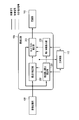
- FIG. 2 is a specific block diagram showing the wrinkle correction unit.
- FIG. 3A is a schematic diagram for explaining a technique for estimating the heel component H (x, y) of each pixel of image data.
- FIG. 3B is a diagram illustrating an image of the heel component H (x, y).
- 4A is a diagram showing a certain local region R set in the input image data I.
- FIG. FIG. 4B is a diagram illustrating the local region R set in the image Ha of the heel component H (x, y).
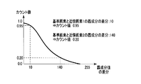
- FIG. 5 is a diagram illustrating a Gaussian function for obtaining a count value when generating a luminance histogram based on the ⁇ component H (x, y).
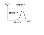
- FIG. 6 is a diagram illustrating a luminance histogram of the haze component H (x, y).
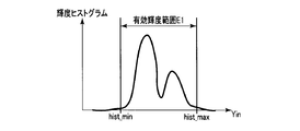
- FIG. 7A is a diagram showing an effective luminance range E1 of a histogram before histogram expansion.
- FIG. 7B is a diagram showing a linear relationship when histogram expansion is performed.
- FIG. 7C is a diagram showing an effective luminance range E2 of the histogram after the histogram expansion.
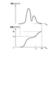
- FIG. 8 is a diagram illustrating a cumulative histogram for realizing histogram flattening.
- FIG. 9 is a diagram showing a shooting operation flowchart.
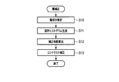
- FIG. 10 is a diagram illustrating a wrinkle correction flowchart.
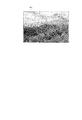
- FIG. 11 is a diagram illustrating an example of a contrast-corrected image (corrected image).
- FIG. 12 is a configuration diagram illustrating a wrinkle correction unit in the second embodiment of the imaging apparatus including the image processing apparatus according to the present invention.
- FIG. 1 is a block diagram of an imaging apparatus to which an image processing apparatus is applied.
- the lens system 100 forms a light image from a subject, and includes a focus lens, a diaphragm 101, and the like.
- the lens system 100 includes an autofocus motor (AF motor) 103.
- the focus lens moves along the optical axis P by driving the AF motor 103.
- the AF motor 103 is driven and controlled by the lens control unit 107.
- An imaging sensor 102 is provided on the optical axis of the lens system 100.
- the image sensor 102 receives the optical image from the lens system 100 and outputs an RGB analog video signal.
- An A / D converter 104 in the camera body 300 is connected to the output end of the image sensor 102.
- the A / D converter 104 converts the analog video signal output from the imaging sensor 102 into a digital video signal.
- the camera main body 300 is equipped with a main control unit 112 composed of a microcomputer or the like.
- the main control unit 112 includes an A / D converter 104, a buffer 105, a photometric evaluation unit 106, a lens control unit 107, an image processing unit 108, a wrinkle correction unit 109, and a compression unit via a bus 301.
- the unit 110 and the output unit 111 are connected.
- the main control unit 112 controls the photometry evaluation unit 106, the lens control unit 107, the image processing unit 108, the wrinkle correction unit 109, the compression unit 110, and the output unit 111 via the bus 301.
- the buffer 105 temporarily stores the digital video signal transferred from the A / D converter 104.
- the photometric evaluation unit 106 measures the light image incident on the imaging sensor 102 from the digital video signal stored in the buffer 105 and evaluates it, and based on the photometric evaluation and the control signal from the main control unit 112.
- the diaphragm 101 of the lens system 100 is controlled and the output level of the analog video signal output from the image sensor 102 is adjusted.
- the image processing unit 108 performs known image processing such as interpolation processing, WB correction processing, and noise reduction processing on the digital video signal stored in the buffer 105, and uses the digital video signal after the image processing as image data. Output.
- the wrinkle correction unit 109 performs contrast correction on the image data transferred from the image processing unit 108, for example, for a region where the contrast is reduced due to the influence of wrinkles. Details of the eyelid correction unit 109 will be described later.
- the compression unit 110 performs a known compression process, for example, a compression process such as JPEG or MPEG, on the image data transferred from the wrinkle correction unit 109.
- a compression process such as JPEG or MPEG
- the output unit 111 displays and outputs a video on a display unit (not shown) based on the image data whose contrast has been corrected by the wrinkle correction unit 109, or a recording medium (for example, a memory card) that does not show the image data compressed by the compression unit 110 To record output.
- a recording medium for example, a memory card
- an external I / F unit 113 is connected to the main control unit 112.
- the external I / F unit 113 is an interface for switching a power switch, a shutter button, or various modes during photographing.
- the A / D converter 104, the buffer 105, the photometric evaluation unit 106, the lens control unit 107, the image processing unit 108, the eyelid correction unit 109, the compression unit 110, and the output unit 111 Is connected to the main control unit 112 via the bus 301, but is not limited thereto.
- the A / D converter 104, the photometric evaluation unit 106, the lens control unit 107, the image processing unit 108, the wrinkle correction unit 109, the compression unit 110, and the output unit 111 may be connected in series. Good.
- the digital video signal output from the A / D converter 104 is sent from the buffer 105 to the photometric evaluation unit 106, the lens control unit 107, the image processing unit 108, the eyelid correction unit 109, the compression unit 110, and the output unit 111. Transferred in order.
- FIG. 2 shows a specific block configuration diagram of the eyelid correction unit 109.
- thick solid arrows indicate the flow of digital video signals
- thin solid arrows indicate the flow of control signals
- dotted arrows indicate the flow of other signals.
- the wrinkle correction unit 109 executes an image processing program stored in a program memory (not shown) under the control of the main control unit 112 to thereby generate a wrinkle component estimation unit (deterioration degree detection unit) 200 and a local histogram generation unit (deterioration degree change). It has functions of a determination unit 201, a correction coefficient calculation unit (correction value setting unit) 202, and a contrast correction unit (correction processing unit) 203.
- the heel component estimation unit 200 detects the degree of deterioration of each pixel of image data acquired from the digital video signal transferred from the image processing unit 108.
- the deterioration degree is a degree of existence of a factor that deteriorates image quality such as contrast or color in image data.
- a factor that degrades the image quality for example, a wrinkle component included in image data when a wrinkled scene is photographed.
- the degree of deterioration is the degree of presence of the soot component.
- the estimation of the haze component is based on the feature that haze has high brightness and low saturation (high brightness white), that is, low contrast or low color reproduction. That is, a pixel having high luminance and low saturation and a certain level is estimated to be a wrinkle component.
- FIG. 3A is a schematic diagram for explaining a method for estimating the ⁇ component H (x, y) from the input image data I
- FIG. 3B shows the image data Ha of the ⁇ component H (x, y).
- the heel component estimation unit 200 calculates the heel component H (x, y) based on the R value, G value, and B value of the pixel at the coordinates (x, y) in the input image data I transferred from the image processing unit 108. Estimate.
- the heel component H (x, y) of the pixel at the coordinates (x, y) is Estimated by (1).
- H (x, y) min (Ir, Ig, Ib) (1)
- the heel component estimation unit 200 performs the calculation of Expression (1) on the entire input image data I. This will be specifically described below.
- the eyelid component estimation unit 200 sets, for example, a scan area (small area) F of a predetermined size for the input image data I.
- the size of the scan region F is, for example, a predetermined size m ⁇ n (m and n are natural numbers) pixels.
- the center pixel of the scan region F is set as a reference pixel.
- each pixel around the reference pixel in the scan region F is set as a neighboring pixel.
- the scan area F is formed in a size of 5 ⁇ 5 pixels, for example.
- the scan area F may be one pixel.
- the heel component estimation unit 200 calculates (Ir, Ig, Ib) of each pixel in the scan region F while shifting the position of the scan region F, and calculates the minimum value among them as the heel component H of the reference pixel. Let (x, y).
- the value of min (Ir, Ig, Ib) becomes large. That is, the haze component H (x, y) takes a large value in a region with high luminance and low saturation.
- the pixel value in the low luminance or high saturation region has a small value of min (Ir, Ig, Ib) because one of the R value, G value, and B value is small. That is, the haze component H (x, y) has a small value in the low luminance or high saturation region.
- the haze component H (x, y) has a larger value as the haze density in the scene is higher (as the haze white color is higher), and a smaller value as the haze density is lower (as the haze white color becomes lighter). It has the characteristics.
- the soot component is not limited to that calculated by the equation (1). That is, any index that indicates the degree of high brightness and low saturation can be used as a wrinkle component. For example, a local contrast value, edge strength, subject distance, etc. can be used as the wrinkle component.
- the local histogram generation unit 201 uses the wrinkle component H (x, y) transferred from the wrinkle component estimation unit 200 to generate a wrinkle component H (in a local region including the reference pixel of the input image data I and neighboring pixels around it.
- the degree of change of x, y) is determined.
- the degree of change of the ⁇ component H (x, y) is determined by the distribution of the ⁇ component H (x, y) in the local region, specifically, the ⁇ component H (x, y) between the reference pixel and the neighboring pixels in the local region. It is determined based on the difference of y).
- the local histogram generation unit 201 generates a luminance histogram for a local region including neighboring pixels for each reference pixel based on the video signal transferred from the image processing unit 108 and the haze component transferred from the haze component estimation unit 200.
- General histogram generation is performed by regarding pixel values in a target local region as luminance values and counting the frequency of pixel values one by one.
- the count value for the pixel value of the neighboring pixel is weighted according to the value of the heel component of the reference pixel and the neighboring pixel in the local region.
- the count value for the pixel value of the neighboring pixels takes a value in the range of 0.0 to 1.0, for example. Further, the count value is set so that the value decreases as the difference between the wrinkle component between the reference pixel and the neighboring pixel increases, and the value increases as the difference between the wrinkle component between the reference pixel and the neighboring pixel decreases.
- FIG. 4A shows a certain local region R set in the image data I
- FIG. 4B shows the same local region R as the image data I set in the image data Ha of the haze component H (x, y).
- the local region R is formed with a size of 7 ⁇ 7 pixels, for example.
- a reference pixel SG and two neighboring pixels KG1 and KG2 are shown in the local region R in the image data I shown in FIG. 4A.
- the reference pixel SG has, for example, luminance (pixel value) “160”.
- the neighboring pixel KG1 has, for example, luminance (pixel value) “170”, and the neighboring pixel KG2 has, for example, luminance (pixel value) “40”.
- luminance pixel value
- luminance “40” is 1 count.
- the reference pixel SG has a haze component “150”, and the neighboring pixel KG1 has a haze component “160”, for example.
- the neighboring pixel KG2 has, for example, a haze component “10”.
- a count value for the pixel value of each pixel in the local region R in the input image data I is set.
- a Gaussian function as shown in FIG. 5 has a count value such that the value decreases as the difference between the reference pixel and the neighboring pixel increases, and the value increases as the difference between the reference pixel and the neighboring pixel decreases.
- the count value of the neighboring pixel KG1 in which the difference of the heel component H (x, y) is 10 is 0.95.
- the count value of the neighboring pixel KG2 in which the difference of the haze component H (x, y) is 140 is 0.20. Therefore, the luminance “170” is 0.95 count and the luminance “40” is 0.20 count.
- An example of the histogram generated in this way is shown in FIG. This histogram is a luminance histogram in the local region R to which the reference pixel SG belongs. As a result, the correction coefficient calculated by the correction coefficient calculation unit 202 described later can be calculated with an optimum value.
- the count value may not be calculated by a Gaussian function.
- the count value may be determined in accordance with a relationship in which the smaller the difference of the heel component H (x, y) between the reference pixel and the neighboring pixel, the smaller the value.
- a lookup table or a table that approximates a broken line may be used.
- the difference between the values of each haze component H (x, y) between the reference pixel and the neighboring pixels is compared with a predetermined threshold value, and the neighboring pixels to be counted are selected based on the comparison result. You may make it do. For example, neighboring pixels whose wrinkle component difference is larger than a predetermined threshold value may not be counted.
- the degree of change of the soot component H (x, y) can be calculated not only by the difference but also by the ratio.
- the value of the ratio takes a value from 0.0 to 1.0. If the difference between H1 and H2 is small, the ratio value approaches 1.0, and if the difference between H1 and H2 is large, the ratio value approaches 0.0. In this way, the ratio value of the heel component can be handled in the same manner as the difference of the heel component.
- the correction coefficient calculation unit 202 sets a correction coefficient as a correction value for correcting the deterioration of the reference pixel SG of the image data I based on the luminance histogram generated by the local histogram generation unit 201. This correction coefficient is for correcting the contrast of the reference pixel, for example. Then, the correction coefficient calculation unit 202 transfers the correction coefficient to the contrast correction unit 203.
- a histogram expansion is described as an example of the contrast correction method.
- 7A to 7C are explanatory diagrams of histogram expansion.
- the histogram expansion is a process for enhancing the contrast by, for example, expanding the effective luminance range E1 of the luminance histogram shown in FIG. 7A to the effective luminance range E2 of the luminance histogram shown in FIG. 7C.
- the minimum luminance hist_min and the maximum luminance hist_max in the effective luminance range E1 of the histogram are set to the minimum value 0 and the maximum value 255 (in the case of 8 bits) that the luminance data can take as shown in FIG. It is implemented by performing the linear transformation shown in FIG.
- This histogram expansion is expressed by the following equation (2).
- c_a 255 / (hist_max-hist_min)
- c_b -c_a ⁇ hist_min
- hist_min represents the minimum luminance in the effective luminance range of the histogram
- hist_max represents the maximum luminance in the effective luminance range of the histogram.
- the correction coefficients c_a and c_b are calculated so that the minimum luminance hist_min is 0 and the maximum luminance hist_max is 255. Using these correction coefficients c_a and c_b, linear transformation represented by the following equation (3) is performed.
- Yin is the luminance value (pixel value) of the input image data I before the histogram expansion
- Yout is the luminance value (pixel value) of the input image data I after the histogram expansion.
- the calculation of the minimum luminance hist_min and the maximum luminance hist_max can be realized by comparing the accumulated count value of the luminance histogram with a predetermined threshold value, for example. By setting a predetermined threshold value, it is possible to eliminate the influence of a small pixel value, for example, noise.
- the correction coefficients c_a and c_b are calculated so that the minimum luminance hist_min is 0 and the maximum luminance hist_max is 255.
- the output value 0 corresponding to the minimum luminance hist_min and the output value 255 corresponding to the maximum luminance hist_max may be set to arbitrary values.
- the minimum luminance hist_min and the maximum luminance hist_max may be determined according to the value of the wrinkle component of the reference pixel. For example, when the value of the heel component is large, the output value corresponding to the minimum luminance hist_min may be set to 0, and the output value corresponding to the maximum luminance hist_max may be set to 255. Further, when the value of the heel component is small, the output value corresponding to the minimum luminance hist_min may be set to 20 and the output value corresponding to the maximum luminance hist_max may be set to 235.
- histogram extension is used as means for realizing contrast correction.
- histogram flattening can be applied as means for realizing contrast correction.
- a method for realizing histogram flattening a method using a cumulative histogram as shown in FIG. 8 or a table approximating a polygonal line can be applied. The cumulative histogram is obtained by sequentially accumulating the frequent values of the luminance histogram.
- the contrast correction unit 203 has a haze component H (x, y) transferred from the haze component estimation unit 200 with respect to the digital video signal transferred from the image processing unit 108 and a correction coefficient transferred from the correction coefficient calculation unit 202. Based on c_a and c_b, contrast correction of the reference pixel SG1 of the image data I is performed.
- the calculation formula for contrast correction of luminance data is shown in the following formula (4).
- W is a weighting coefficient obtained by normalizing the value of the heel component H (x, y) to a value of 0.0 to 1.0.
- the weight coefficient w increases as the value of the heel component H (x, y) increases.
- Yt is target brightness data calculated using the correction coefficients c_a and c_b transferred from the correction coefficient calculation unit 202.
- the luminance data Yout after contrast correction is a value obtained by combining the luminance data Yin of the input image data I and the target luminance data Yt according to the weight coefficient w. From Expression (4), it is possible to apply contrast correction only to a region where the value of the haze component H (x, y) is large.
- step S1 the external I / F unit 113 stores various settings relating to shooting input by the operation, such as various signals and header information, to the main control unit 112. send.
- the main control unit 112 switches to the shooting mode.
- the image sensor 102 receives the light image from the lens system 100 and outputs an analog video signal.
- the analog video signal is converted into a digital video signal by the A / D converter 104, transferred to the buffer 105, and temporarily stored.
- the image processing unit 108 performs known image processing such as interpolation processing, WB correction processing, and noise reduction processing on the digital video signal stored in the buffer 105, and the digital video signal after the image processing is performed. Is transferred to the wrinkle correction unit 109.
- step S3 the eyelid correction unit 109 performs contrast correction on the digital video signal transferred from the image processing unit 108, for example, for a region where the contrast is reduced due to the effect of eyelids in accordance with the eyelid correction flowchart shown in FIG. .
- wrinkle component estimation section 200 estimates the value of wrinkle component H (x, y) of each pixel of input image data I transferred from image processing section 108 in step S10. Then, wrinkle component estimation section 200 transfers the estimated wrinkle component H (x, y) to local histogram generation section 201 and contrast correction section 203.
- step S ⁇ b> 11 the local histogram generation unit 201 determines the ⁇ component H (x) based on the image data I input from the image processing unit 108 and the ⁇ component H (x, y) transferred from the ⁇ component estimation unit 200. , Y), a luminance histogram for each local region R of the input image data I is generated. Then, the local histogram generation unit 201 transfers the generated luminance histogram to the correction coefficient calculation unit 202.
- step S12 the correction coefficient calculation unit 202 sets the correction coefficients c_a and c_b based on the luminance histogram generated by the local histogram generation unit 201. Then, the correction coefficient calculation unit 202 transfers the correction coefficients c_a and c_b to the contrast correction unit 203.
- step S ⁇ b> 13 the contrast correction unit 203 inputs the input image data based on the correction coefficients c_a and c_b transferred from the correction coefficient calculation unit 202 and the haze component H (x, y) transferred from the haze component estimation unit 200. I is corrected. Then, the contrast correction unit 203 transfers the wrinkle-corrected input image data I to the compression unit 110.
- the compression unit 110 in step S4, contrast-corrected input image data I transferred from the wrinkle correction unit 109, that is, input image data I that has been corrected based on the wrinkle component H (x, y).
- the image data is transferred to the output unit 111 after performing a compression process such as known JPEG or MPEG.
- the output unit 111 records the compressed image data I transferred from the compression unit 110 on a memory card or the like.
- an image based on the image data I corrected by the wrinkle correction unit 109 is separately displayed on the display.
- FIG. 11 shows an example of contrast-corrected image (corrected image) data Hb.
- This image Hb has been subjected to appropriate contrast correction even if both the region that is blurred and the region that is not blurred are mixed in the input image data I.
- This image Hb has no luminance unevenness.
- the wrinkle correction unit 109 detects the wrinkle component H (x, y) for each pixel of the input image data I using the wrinkle component estimation unit 200, and the local histogram generation unit. 201, the difference between the heel component H (x, y) to determine the degree of change of the heel component H (x, y) in the local region R of the input image data I based on the heel component H (x, y).
- the correction coefficient calculation unit 202 sets correction coefficients c_a and c_b based on the luminance histogram, and the contrast correction unit 203 corrects the input image data I based on the correction coefficients c_a and c_b.
- contrast correction when contrast correction is performed, only neighboring pixels having a value of a haze component equivalent to that of the reference pixel are used even if both the haze region and the non-bright region are mixed in the input image data I.
- appropriate contrast correction can be performed for each local region R. Further, the effect of contrast correction is not reduced and luminance unevenness does not occur at the boundary between both areas where the area is blurred and the area where the shadow is not blurred.
- FIG. 12 shows a configuration diagram of the eyelid correction unit 109.
- the wrinkle correction unit 109 is provided with a local minimum / maximum calculation unit 204 as a deterioration degree change determination unit in place of the local histogram generation unit 201 shown in FIG.
- the input image data I is transferred from the image processing unit 108, and the haze component H (x, y) is transferred from the haze component estimation unit 200.
- the local minimum / maximum calculation unit 204 scans the input image data I for luminance (pixel value) for each local region R, and detects the minimum luminance and the maximum luminance.
- the local minimum / maximum calculation unit 204 When detecting the minimum luminance and the maximum luminance, the local minimum / maximum calculation unit 204 is an image of the heel component H (x, y) in advance so that the minimum luminance and the maximum luminance can be detected from the area to which the reference pixel SG belongs. Among the data Ha, neighboring pixels having a large difference in the value of the heel component H (x, y) from the reference pixel SG are excluded from the scan target. The local minimum / maximum calculation unit 204 transfers the minimum luminance and the maximum luminance to the correction coefficient calculation unit 202.
- the local minimum / maximum calculation unit 204 is not limited to excluding neighboring pixels having a large difference in values of the wrinkle component (x, y) from the scan target.
- the local minimum / maximum calculation unit 204 may detect the minimum luminance and the maximum luminance from the pixel value after filtering with a weighted average filter based on the pixel value of the reference pixel SG.
- the correction coefficient calculation unit 202 calculates a correction coefficient based on the minimum luminance and the maximum luminance transferred from the local minimum / maximum calculation unit 204. Then, the correction coefficient calculation unit 202 transfers the correction coefficient to the contrast correction unit 203.
- correction coefficients are calculated for all pixels in the input image data I, but the present invention is not limited to this.
- the input image data I to the image processing unit 108 may be reduced, and a correction coefficient may be calculated from an image that has been resized (reduced and resized) thereafter.
- a correction coefficient may be determined for all the pixels of the reduced and resized image, and thereafter, a correction coefficient for each pixel in the input image data I may be calculated by interpolation processing.
- the wrinkle correction unit 109 may generate a reduced image of the input image data I and detect the degree of deterioration of the wrinkle component H (x, y) or the like from the reduced image.
- the shade of the haze component is referred to as the degree of deterioration, but is not limited to this, and a phenomenon having a characteristic that the contrast decreases with high brightness and low saturation, for example, a haze component, a fog component,
- a phenomenon having a characteristic that the contrast decreases with high brightness and low saturation for example, a haze component, a fog component
- a phenomenon such as a component that becomes turbid, a component of smoke, a component caused by backlighting, or a component caused by flare occurs.
Landscapes
- Engineering & Computer Science (AREA)
- Physics & Mathematics (AREA)
- General Physics & Mathematics (AREA)
- Theoretical Computer Science (AREA)
- Multimedia (AREA)
- Signal Processing (AREA)
- Facsimile Image Signal Circuits (AREA)
- Image Processing (AREA)
- Color Image Communication Systems (AREA)
- Studio Devices (AREA)
Abstract
画像処理装置は、画像データの画素毎の劣化度を検出する劣化度検出部(200)と、劣化度に基づいて画像データの基準画素とその周辺の近傍画素とを含む所定領域における劣化度の変化の度合いを判定する劣化度変化判定部(201)と、劣化度の変化の度合いに基づいて基準画素の劣化を補正するための補正値を設定する補正値設定部(202)と、補正値に基づいて基準画素のデータを補正する補正処理部(203)とを備える。
Description
本発明は、例えば霞、靄又は霧等の影響によりコントラスト又は色彩等の画質が損なわれた画像の補正を行う画像処理装置、撮像装置、画像処理方法及び画像処理装置の画像処理プログラムを記憶した記憶媒体に関する。
大気中に発生する霞、靄、霧等の影響によって画像のコントラスト又は色彩等の画質が失われることがある。例えば、屋外において遠方の山等の風景写真を撮影する場合がある。この撮影で遠方の山に霞が掛かっていると、この状況で撮影された画像の品位は損なわれてしまう。この場合、遠方の山に対する視認性は低下する。
このような問題を解決する技術として例えば日本国特許第4982475号公報がある。この日本国特許第4982475号公報は、画像の局所領域毎に輝度の最大、最小を算出し、これら最大、最小の差が大きくなるように適応的なコントラスト補正を行うことを開示する。この日本国特許第4982475号公報であれば、霞のない領域と霞のある領域とが混在する画像においても、十分なコントラスト補正を行うことができる。
日本国特許第4982475号公報は、局所領域毎の輝度分布に基づき注目画素に対するコントラスト補正係数を決定する。このコントラストの補正では、例えば輝度のヒストグラムの伸張又は平坦化が用いられる。コントラスト補正が行わるときに局所領域内に霞んでいる領域と霞んでいない領域との両領域が混在すると、局所領域毎の輝度分布には、両領域の輝度情報が含まれる。このため、単純なヒストグラム伸張又は平坦化では、期待通りのコントラスト補正をすることが困難になる。具体的には、両領域の境界で補正の効果が小さくなったり、補正後に輝度ムラが発生する可能性がある。
本発明は前記の事情に鑑みてなされたものであり、局所領域毎に適切なコントラスト補正を可能とする画像処理装置、撮像装置、画像処理方法及び画像処理装置の画像処理プログラムを記憶した記憶媒体を提供することを目的とする。
本発明の第1の態様に係る画像処理装置は、画像データの画素毎の劣化度を検出する劣化度検出部と、前記劣化度に基づいて前記画像データの基準画素とその周辺の近傍画素とを含む所定領域内における前記劣化度の変化の度合いを判定する劣化度変化判定部と、前記劣化度の変化の度合いに基づいて前記基準画素の劣化を補正するための補正値を設定する補正値設定部と、前記補正値に基づいて前記基準画素のデータを補正する補正処理部とを具備する。
本発明の第2の態様に係る撮像装置は、前記画像処理装置と、前記画像データを取得する撮像部とを具備する。
本発明の第3の態様に係る画像処理方法は、画像データの画素毎の劣化度を検出することと、前記劣化度に基づいて前記画像データの基準画素とその周辺の近傍画素とを含む所定領域内における前記劣化度の変化の度合いを判定することと、前記劣化度の変化の度合いに基づいて前記基準画素の劣化を補正するための補正値を設定することと、前記補正値に基づいて前記基準画素のデータを補正することとを具備する。
本発明の第4の態様に係る画像処理プログラムを記憶した記憶媒体は、コンピュータに、画像データの画素毎の劣化度を検出することと、前記劣化度に基づいて前記画像データの基準画素とその周辺の近傍画素とを含む所定領域内における前記劣化度の変化の度合いを判定することと、前記劣化度の変化の度合いに基づいて前記基準画素の劣化を補正するための補正値を設定することと、前記補正値に基づいて前記基準画素のデータを補正することとを実行させるプログラムを記憶している。
本発明によれば、局所領域毎に適切なコントラスト補正ができる画像処理装置、撮像装置、画像処理方法及び画像処理装置の画像処理プログラムを記憶した記憶媒体を提供できる。
[第1の実施の形態]
以下、本発明の第1の実施の形態について図面を参照して説明する。
図1は画像処理装置を適用した撮像装置のブロック構成図を示す。レンズ系100は、被写体からの光像を結像するもので、フォーカスレンズ及び絞り101等を含む。このレンズ系100は、オートフォーカス用モータ(AFモータ)103を備えている。AFモータ103の駆動によりフォーカスレンズは、光軸Pに沿って移動する。AFモータ103は、レンズ制御部107により駆動制御される。
以下、本発明の第1の実施の形態について図面を参照して説明する。
図1は画像処理装置を適用した撮像装置のブロック構成図を示す。レンズ系100は、被写体からの光像を結像するもので、フォーカスレンズ及び絞り101等を含む。このレンズ系100は、オートフォーカス用モータ(AFモータ)103を備えている。AFモータ103の駆動によりフォーカスレンズは、光軸Pに沿って移動する。AFモータ103は、レンズ制御部107により駆動制御される。
レンズ系100の光軸上には、撮像センサ102が設けられている。撮像センサ102は、レンズ系100からの光像を受光し、RGBのアナログ映像信号を出力する。この撮像センサ102の出力端には、カメラ本体300内のA/D変換器104が接続されている。A/D変換器104は、撮像センサ102から出力されるアナログ映像信号をデジタル映像信号に変換する。
また、カメラ本体300には、マイクロコンピュータ等から成る主制御部112が搭載されている。この主制御部112には、バス301を介してA/D変換器104と、バッファ105と、測光評価部106と、レンズ制御部107と、画像処理部108と、霞補正部109と、圧縮部110と、出力部111とが接続されている。この主制御部112は、バス301を介して測光評価部106と、レンズ制御部107と、画像処理部108と、霞補正部109と、圧縮部110と、出力部111とをそれぞれ制御する。
また、カメラ本体300には、マイクロコンピュータ等から成る主制御部112が搭載されている。この主制御部112には、バス301を介してA/D変換器104と、バッファ105と、測光評価部106と、レンズ制御部107と、画像処理部108と、霞補正部109と、圧縮部110と、出力部111とが接続されている。この主制御部112は、バス301を介して測光評価部106と、レンズ制御部107と、画像処理部108と、霞補正部109と、圧縮部110と、出力部111とをそれぞれ制御する。
バッファ105は、A/D変換器104から転送されるデジタル映像信号を一時的に保存する。
測光評価部106は、バッファ105に保存されているデジタル映像信号から撮像センサ102に入射する光像を測光してその評価を行い、この測光評価と主制御部112からの制御信号とに基づいてレンズ系100の絞り101を制御し、かつ撮像センサ102から出力されるアナログ映像信号の出力レベル等を調整する。
測光評価部106は、バッファ105に保存されているデジタル映像信号から撮像センサ102に入射する光像を測光してその評価を行い、この測光評価と主制御部112からの制御信号とに基づいてレンズ系100の絞り101を制御し、かつ撮像センサ102から出力されるアナログ映像信号の出力レベル等を調整する。
画像処理部108は、バッファ105に保存されているデジタル映像信号に対して公知の補間処理、WB補正処理、ノイズ低減処理などの画像処理を行い、当該画像処理後のデジタル映像信号を画像データとして出力する。
霞補正部109は、画像処理部108から転送された画像データに対して例えば霞の影響によりコントラストが低下した領域に対してコントラスト補正を行う。霞補正部109の詳細については後で説明する。
圧縮部110は、霞補正部109から転送された画像データに対して公知の圧縮処理、例えばJPEG、MPEG等の圧縮処理を行う。
出力部111は、霞補正部109でコントラスト補正された画像データに基づいて図示しない表示部に映像を表示出力したり、圧縮部110で圧縮された画像データを図示しない記録媒体(例えばメモリカード)に記録出力したりする。
また、主制御部112には、外部I/F部113が接続されている。この外部I/F部113は、電源スイッチ、シャッターボタン、又は撮影時の各種モードの切り替えなどを行うためのインターフェースである。
なお、図1では、A/D変換器104と、バッファ105と、測光評価部106と、レンズ制御部107と、画像処理部108と、霞補正部109と、圧縮部110と、出力部111とは、バス301を介して主制御部112に接続されているが、これに限ることはない。例えば、A/D変換器104と、測光評価部106と、レンズ制御部107と、画像処理部108と、霞補正部109と、圧縮部110と、出力部111とは、直列接続されてもよい。この場合、A/D変換器104から出力されるデジタル映像信号は、バッファ105から測光評価部106、レンズ制御部107、画像処理部108、霞補正部109、圧縮部110、出力部111にこの順で転送される。
次に、霞補正部109について説明する。図2は霞補正部109の具体的なブロック構成図を示す。同図中において、太い実線の矢印はデジタル映像信号の流れを示し、細い実線の矢印は制御信号の流れを示し、点線の矢印はその他の信号の流れを示す。
霞補正部109は、主制御部112の制御によって図示しないプログラムメモリに記憶された画像処理プログラムを実行することにより霞成分推定部(劣化度検出部)200と、局所ヒストグラム生成部(劣化度変化判定部)201と、補正係数算出部(補正値設定部)202と、コントラスト補正部(補正処理部)203との機能を有するものとなる。
霞補正部109は、主制御部112の制御によって図示しないプログラムメモリに記憶された画像処理プログラムを実行することにより霞成分推定部(劣化度検出部)200と、局所ヒストグラム生成部(劣化度変化判定部)201と、補正係数算出部(補正値設定部)202と、コントラスト補正部(補正処理部)203との機能を有するものとなる。
具体的に説明すると、霞成分推定部200は、画像処理部108から転送されるデジタル映像信号から取得される画像データの画素毎の劣化度を検出する。ここで、劣化度とは、画像データの中の、コントラスト又は色彩といった画質を劣化させる要因の存在する度合いである。画質を劣化させる要因としては、例えば、霞がかかったシーンを撮影したときに画像データ中に含まれる霞成分である。以下、劣化度は、霞成分の存在する程度であるとして説明を続ける。
霞成分の推定は、霞が高輝度でかつ低彩度(高輝度白色)、すなわち低コントラスト又は低色再現であるという特徴に基づいている。すなわち、高輝度でかつ低彩度である程度が高い画素は、霞成分であると推定される。
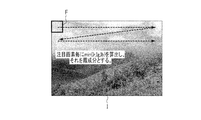
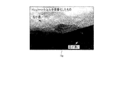
図3Aは入力画像データIから霞成分H(x,y)を推定するための手法を説明するための模式図を示し、図3Bは霞成分H(x,y)の画像データHaを示す。
霞成分推定部200は、画像処理部108から転送される入力画像データIにおける座標(x,y)にある画素のR値,G値,B値に基づいて霞成分H(x,y)の推定を行う。
霞成分推定部200は、画像処理部108から転送される入力画像データIにおける座標(x,y)にある画素のR値,G値,B値に基づいて霞成分H(x,y)の推定を行う。
ここで、座標(x,y)におけるR値、G値、B値をそれぞれIr、Ig、Ibとすると、座標(x,y)にある画素の霞成分H(x,y)は、次式(1)により推定される。
H(x,y)=min(Ir,Ig,Ib) …(1)
霞成分推定部200は、式(1)の演算を入力画像データIの全体に対して行う。以下、具体的に説明する。霞成分推定部200は、入力画像データIに対して例えば所定サイズのスキャン領域(小領域)Fを設定する。スキャン領域Fのサイズは、例えば所定サイズm×n(m,nは自然数)画素である。以下、スキャン領域Fの中心の画素を基準画素とする。また、スキャン領域Fにおける基準画素の周辺の各画素を近傍画素とする。スキャン領域Fは、例えば5×5画素のサイズに形成されている。スキャン領域Fは、1画素であってもよい。
H(x,y)=min(Ir,Ig,Ib) …(1)
霞成分推定部200は、式(1)の演算を入力画像データIの全体に対して行う。以下、具体的に説明する。霞成分推定部200は、入力画像データIに対して例えば所定サイズのスキャン領域(小領域)Fを設定する。スキャン領域Fのサイズは、例えば所定サイズm×n(m,nは自然数)画素である。以下、スキャン領域Fの中心の画素を基準画素とする。また、スキャン領域Fにおける基準画素の周辺の各画素を近傍画素とする。スキャン領域Fは、例えば5×5画素のサイズに形成されている。スキャン領域Fは、1画素であってもよい。
霞成分推定部200は、図3Aに示すようにスキャン領域Fの位置をずらしながらスキャン領域Fにおける各画素の(Ir,Ig,Ib)を算出し、そのうちの最小値を基準画素の霞成分H(x,y)とする。
画像データIにおける高輝度かつ低彩度な領域の画素値は、R値,G値,B値が同等かつ大きいので、min(Ir,Ig,Ib)の値は大きくなる。すなわち、高輝度かつ低彩度な領域では、霞成分H(x,y)が大きな値となる。
これに対して低輝度又は高彩度の領域の画素値は、R値,G値,B値のいずれかが小さいので、min(Ir,Ig,Ib)の値は小さくなる。すなわち、低輝度や高彩度の領域では、霞成分H(x,y)が小さな値となる。
しかるに、霞成分H(x,y)は、シーンにおける霞の濃度が濃いほど(霞の白色が濃くなるほど)大きな値となり、霞の濃度が薄いほど(霞の白色が薄くなるほど)小さな値となるという特徴を持つ。
ここで、霞成分は、式(1)によって計算されるものに限られない。すなわち、高輝度かつ低彩度の程度を示す指標であれば霞成分として使用され得る。例えば、局所コントラスト値、エッジ強度、被写体距離等も霞成分として使用され得る。
局所ヒストグラム生成部201は、霞成分推定部200から転送された霞成分H(x,y)に基づいて入力画像データIの基準画素とその周辺の近傍画素とを含む局所領域における霞成分H(x,y)の変化の度合いを判定する。この霞成分H(x,y)の変化の度合いは、局所領域における霞成分H(x,y)の分布、具体的には局所領域内の基準画素と近傍画素との霞成分H(x,y)の差分に基づいて判定される。
すなわち、局所ヒストグラム生成部201は、画像処理部108から転送される映像信号と霞成分推定部200から転送される霞成分に基づき、基準画素毎にその近傍画素を含む局所領域に対する輝度ヒストグラムを生成する。一般的なヒストグラム生成は、対象の局所領域内の画素値を輝度値とみなし、画素値の頻度を1ずつカウントすることで行われる。これに対し、本実施の形態では、局所領域内の基準画素と近傍画素の霞成分の値に応じて、近傍画素の画素値に対するカウント値に重み付けがされる。近傍画素の画素値に対するカウント値は、例えば0.0~1.0の範囲の値をとるものである。また、このカウント値は、基準画素と近傍画素の霞成分の差分が大きいほど値が小さくなり、基準画素と近傍画素の霞成分の差分が小さいほど値が大きくなるように設定される。
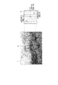
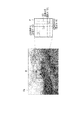
以下、輝度ヒストグラムの生成手法について具体的に説明する。図4Aは画像データIに設定されるある局所領域Rを示し、図4Bは霞成分H(x,y)の画像データHaに設定される画像データIと同じ局所領域Rを示す。局所領域Rは、例えば7×7画素のサイズに形成されている。
図4Aに示す画像データI中の局所領域Rでは、基準画素SGと、2つの近傍画素KG1、KG2とが示されている。基準画素SGは、例えば輝度(画素値)「160」を有する。近傍画素KG1は、例えば輝度(画素値)「170」を有し、近傍画素KG2は、例えば輝度(画素値)「40」を有する。この場合、一般的なヒストグラム生成では、輝度「160」が1カウント、輝度「170」が1カウント、輝度「40」が1カウントになる。輝度だけでヒストグラムを生成した場合、高輝度かつ高彩度の画素も高輝度かつ低彩度の画素と同じようにカウントされてしまう。
図4Aに示す画像データI中の局所領域Rでは、基準画素SGと、2つの近傍画素KG1、KG2とが示されている。基準画素SGは、例えば輝度(画素値)「160」を有する。近傍画素KG1は、例えば輝度(画素値)「170」を有し、近傍画素KG2は、例えば輝度(画素値)「40」を有する。この場合、一般的なヒストグラム生成では、輝度「160」が1カウント、輝度「170」が1カウント、輝度「40」が1カウントになる。輝度だけでヒストグラムを生成した場合、高輝度かつ高彩度の画素も高輝度かつ低彩度の画素と同じようにカウントされてしまう。
図4Bに示す霞成分H(x,y)の画像データHa中の局所領域Rにおいて、基準画素SGは霞成分「150」を有し、近傍画素KG1は例えば霞成分「160」を有し、近傍画素KG2は例えば霞成分「10」を有する。本実施の形態における輝度ヒストグラムの生成では、霞成分H(x,y)の画像データHaにおける局所領域R内の基準画素と各近傍画素との霞成分H(x,y)の差に応じて、入力画像データI中の局所領域Rにおける各画素の画素値に対するカウント値が設定される。基準画素と近傍画素の霞成分の差分が大きいほど値が小さくなり、基準画素と近傍画素の霞成分の差分が小さいほど値が大きくなるようなカウント値は、例えば図5に示すようなガウシアン関数を用いて算出される。図5のガウシアン関数では、例えば、霞成分H(x,y)の差分が10である近傍画素KG1のカウント値は0.95である。また、霞成分H(x,y)の差分が140である近傍画素KG2のカウント値は0.20である。したがって、輝度「170」が0.95カウント、輝度「40」が0.20カウントとなる。このようにして生成されるヒストグラムの例を図6に示す。このヒストグラムは、基準画素SGが属する局所領域Rにおける輝度ヒストグラムである。この結果、後述する補正係数算出部202により算出される補正係数を最適な値で算出することができる。
なお、カウント値は、ガウシアン関数によって算出されなくてもよい。カウント値は、基準画素と近傍画素との霞成分H(x,y)の差分が大きい程、小さい値になる関係に従って決定されればよい。例えば、ルックアップテーブルや折れ線近似したテーブルを使用してもよい。
また、基準画素と近傍画素との間の各霞成分H(x,y)の値の差分と所定の閾値とを比較し、当該比較の結果に基づいてカウントの対象とする近傍画素を取捨選択するようにしてもよい。例えば、霞成分の差分が所定の閾値よりも大きい近傍画素についてはカウントの対象としないようにしてもよい。
また、霞成分H(x,y)の変化の度合いは、差分だけでなく、比によっても算出され得る。例えば、基準画素の霞成分H1=140、近傍画素の霞成分H2=70である場合、霞成分の比は、H2/H1=70/140=0.5となる。このように、分母にH1とH2のうちの大きいほうを用いると、比の値は、0.0から1.0の値をとる。H1とH2の差が小さければ比の値は1.0に近づき、H1とH2の差が大きければ比の値は0.0に近づく。このようにして霞成分の比の値を霞成分の差分と同様に扱うことが可能である。
補正係数算出部202は、局所ヒストグラム生成部201により生成される輝度ヒストグラムに基づいて画像データIの基準画素SGの劣化を補正するための補正値としての補正係数を設定する。この補正係数は、例えば基準画素のコントラストを補正するためのものである。そして、補正係数算出部202は、当該補正係数をコントラスト補正部203に転送する。
本実施の形態では、コントラスト補正手法としてヒストグラム伸張を例に説明する。図7A乃至図7Cは、ヒストグラム伸張の説明図を示す。ヒストグラム伸張は、例えば図7Aに示す輝度ヒストグラムの有効輝度範囲E1を図7Cに示す輝度ヒストグラムの有効輝度範囲E2に拡げることでコントラストを強調する処理である。
例えばヒストグラム伸張は、図7Aに示すようにヒストグラムの有効輝度範囲E1における最小輝度hist_min、最大輝度hist_maxを、図7Cに示すような輝度データの取り得る最小値0、最大値255(8bitの場合)まで拡げるような図7Bに示す線形変換を行うことで実施される。このヒストグラム伸張は、次式(2)により表される。
c_a = 255/(hist_max-hist_min)
c_b = ‐c_a・hist_min …(2)
c_a、c_bはコントラスト補正のための補正係数を表し、hist_minはヒストグラムの有効輝度範囲の最小輝度を表し、hist_maxはヒストグラムの有効輝度範囲の最大輝度を表す。補正係数c_a、c_bは、最小輝度hist_minが0に、最大輝度hist_maxが255になるように算出される。これらの補正係数c_a、c_bを用いて次式(3)で示す線形変換が行われる。
Yout=c_a × Yin + c_b …(3)
Yinはヒストグラム伸張前の入力画像データIの輝度値(画素値)であり、Youtはヒストグラム伸張後の入力画像データIの輝度値(画素値)である。
c_a = 255/(hist_max-hist_min)
c_b = ‐c_a・hist_min …(2)
c_a、c_bはコントラスト補正のための補正係数を表し、hist_minはヒストグラムの有効輝度範囲の最小輝度を表し、hist_maxはヒストグラムの有効輝度範囲の最大輝度を表す。補正係数c_a、c_bは、最小輝度hist_minが0に、最大輝度hist_maxが255になるように算出される。これらの補正係数c_a、c_bを用いて次式(3)で示す線形変換が行われる。
Yout=c_a × Yin + c_b …(3)
Yinはヒストグラム伸張前の入力画像データIの輝度値(画素値)であり、Youtはヒストグラム伸張後の入力画像データIの輝度値(画素値)である。
最小輝度hist_minと最大輝度hist_maxとの算出は、それぞれ例えば輝度ヒストグラムの累積カウント値と所定の閾値を比較することで実現できる。所定の閾値の設定により頻値の小さな画素値、例えばノイズの影響を排除できる。
なお、式(2)では、最小輝度hist_minが0に、最大輝度hist_maxが255になるように補正係数c_a、c_bが算出される。しかしながら、最小輝度hist_minに対応する出力値0と最大輝度hist_maxに対応する出力値255は、それぞれ任意の値に設定されてもよい。
なお、式(2)では、最小輝度hist_minが0に、最大輝度hist_maxが255になるように補正係数c_a、c_bが算出される。しかしながら、最小輝度hist_minに対応する出力値0と最大輝度hist_maxに対応する出力値255は、それぞれ任意の値に設定されてもよい。
また、最小輝度hist_minと最大輝度hist_maxは、基準画素の霞成分の値に応じて決定されてもよい。例えば、霞成分の値が大きい場合には、最小輝度hist_minに対応する出力値が0に、最大輝度hist_maxに対応する出力値が255に設定されてもよい。また、霞成分の値が小さい場合には、最小輝度hist_minに対応する出力値が20に、最大輝度hist_maxに対応する出力値が235に設定されてもよい。
又は、本実施の形態では、コントラスト補正の実現手段としてヒストグラム伸張が用いられている。これに対し、コントラスト補正の実現手段として例えばヒストグラム平坦化を適用することも可能である。例えば、ヒストグラム平坦化を実現する方法として図8に示すような累積ヒストグラムを用いる方法、又は折れ線近似したテーブルを適用することも可能である。累積ヒストグラムは、輝度ヒストグラムの頻値を順次累積したものである。
コントラスト補正部203は、画像処理部108から転送されるデジタル映像信号に対して霞成分推定部200から転送される霞成分H(x,y)と、補正係数算出部202から転送される補正係数c_a、c_bとに基づいて画像データIの基準画素SG1のコントラスト補正を行う。輝度データのコントラスト補正の演算式を次式(4)に示す。
Yout=(1.0-w)・Yin+w・Yt
Yt=c_a × Yin + c_b (4)
Yinはコントラスト補正前の入力画像データIの輝度データを示し、Youtはコントラスト補正後の入力画像データIの輝度データを示す。また、wは霞成分H(x,y)の値を0.0~1.0の値に正規化した重み係数である。この重み係数wは、霞成分H(x,y)の値が大きい程値が大きくなる。Ytは補正係数算出部202から転送される補正係数c_a、c_bを用いて計算したターゲットとなる輝度データである。
Yout=(1.0-w)・Yin+w・Yt
Yt=c_a × Yin + c_b (4)
Yinはコントラスト補正前の入力画像データIの輝度データを示し、Youtはコントラスト補正後の入力画像データIの輝度データを示す。また、wは霞成分H(x,y)の値を0.0~1.0の値に正規化した重み係数である。この重み係数wは、霞成分H(x,y)の値が大きい程値が大きくなる。Ytは補正係数算出部202から転送される補正係数c_a、c_bを用いて計算したターゲットとなる輝度データである。
式(4)に示すようにコントラスト補正後の輝度データYoutは、入力画像データIの輝度データYinとターゲットの輝度データYtとを重み係数wに応じて合成した値となる。式(4)より、霞成分H(x,y)の値が大きい領域のみにコントラスト補正を適用することが可能となる。
次に、上記の通り構成された装置による撮影動作について図9に示す撮影動作フローチャートを参照して説明する。
外部I/F部113に対して操作が行われると、当該外部I/F部113は、ステップS1において、操作入力された撮影に関する各種設定、例えば各種信号、ヘッダ情報等を主制御部112に送る。又、外部I/F部113の記録ボタンが押下されると、主制御部112は、撮影モードに切り替わる。撮影モードにおいて、レンズ系100からの光像が撮像センサ102に入射すると、この撮像センサ102は、レンズ系100からの光像を受光し、アナログ映像信号を出力する。このアナログ映像信号は、A/D変換器104によってデジタル映像信号に変換され、バッファ105に転送されて一時的に保存される。
画像処理部108は、ステップS2において、バッファ105に保存されているデジタル映像信号に対して公知の補間処理、WB補正処理、ノイズ低減処理などの画像処理を行い、当該画像処理後のデジタル映像信号を霞補正部109に転送する。
外部I/F部113に対して操作が行われると、当該外部I/F部113は、ステップS1において、操作入力された撮影に関する各種設定、例えば各種信号、ヘッダ情報等を主制御部112に送る。又、外部I/F部113の記録ボタンが押下されると、主制御部112は、撮影モードに切り替わる。撮影モードにおいて、レンズ系100からの光像が撮像センサ102に入射すると、この撮像センサ102は、レンズ系100からの光像を受光し、アナログ映像信号を出力する。このアナログ映像信号は、A/D変換器104によってデジタル映像信号に変換され、バッファ105に転送されて一時的に保存される。
画像処理部108は、ステップS2において、バッファ105に保存されているデジタル映像信号に対して公知の補間処理、WB補正処理、ノイズ低減処理などの画像処理を行い、当該画像処理後のデジタル映像信号を霞補正部109に転送する。
霞補正部109は、ステップS3において、図10に示す霞補正フローチャートに従い、画像処理部108から転送されたデジタル映像信号に対して例えば霞の影響によりコントラストが低下した領域に対してコントラスト補正を行う。
具体的に霞成分推定部200は、ステップS10において、画像処理部108から転送される入力画像データIの各画素の霞成分H(x,y)の値を推定する。そして、霞成分推定部200は、推定した霞成分H(x,y)を局所ヒストグラム生成部201とコントラスト補正部203とに転送する。
具体的に霞成分推定部200は、ステップS10において、画像処理部108から転送される入力画像データIの各画素の霞成分H(x,y)の値を推定する。そして、霞成分推定部200は、推定した霞成分H(x,y)を局所ヒストグラム生成部201とコントラスト補正部203とに転送する。
局所ヒストグラム生成部201は、ステップS11において、画像処理部108から入力された画像データIと、霞成分推定部200から転送される霞成分H(x,y)とに基づき、霞成分H(x,y)の変化の度合いを判定するために、入力画像データIの局所領域R毎における輝度ヒストグラムを生成する。そして、局所ヒストグラム生成部201は、生成した輝度ヒストグラムを補正係数算出部202に転送する。
補正係数算出部202は、ステップS12において、局所ヒストグラム生成部201により生成される輝度ヒストグラムに基づいて補正係数c_a、c_bを設定する。そして、補正係数算出部202は、補正係数c_a、c_bをコントラスト補正部203に転送する。
コントラスト補正部203は、ステップS13において、補正係数算出部202から転送された補正係数c_a、c_bと、霞成分推定部200から転送された霞成分H(x,y)とに基づいて入力画像データIを補正する。そして、コントラスト補正部203は、霞補正された入力画像データIを圧縮部110に転送する。
以下、図9に戻って説明を続ける。霞補正の後、圧縮部110は、ステップS4において、霞補正部109から転送されたコントラスト補正された入力画像データI、すなわち霞成分H(x,y)に基づく補正がされた入力画像データIに対して公知のJPEG、MPEG等の圧縮処理を行って出力部111に転送する。
出力部111は、ステップS5において、圧縮部110から転送された圧縮処理後の画像データIをメモリカード等に記録する。又は、霞補正部109で補正された画像データIに基づく画像を別途ディスプレイに表示する。
図11はコントラスト補正された画像(補正画像)データHbの一例を示す。この画像Hbは、入力画像データI内に霞んでいる領域と霞んでいない領域との両領域が混在したとしても適切なコントラスト補正がされたものとなっている。この画像Hbには、輝度ムラが発生していない。
出力部111は、ステップS5において、圧縮部110から転送された圧縮処理後の画像データIをメモリカード等に記録する。又は、霞補正部109で補正された画像データIに基づく画像を別途ディスプレイに表示する。
図11はコントラスト補正された画像(補正画像)データHbの一例を示す。この画像Hbは、入力画像データI内に霞んでいる領域と霞んでいない領域との両領域が混在したとしても適切なコントラスト補正がされたものとなっている。この画像Hbには、輝度ムラが発生していない。
このように上記第1の実施の形態によれば、霞補正部109において、霞成分推定部200により入力画像データIの画素毎の霞成分H(x,y)を検出し、局所ヒストグラム生成部201により霞成分H(x,y)に基づいて入力画像データIの局所領域R内における霞成分H(x,y)の変化の度合いを判定するために霞成分H(x,y)の差分に応じた輝度ヒストグラムを生成し、補正係数算出部202により輝度ヒストグラムに基づいて補正係数c_a、c_bを設定し、コントラスト補正部203により補正係数c_a、c_bに基づいて入力画像データIを補正する。すなわち、コントラスト補正を行うときに、入力画像データI内に霞んでいる領域と霞んでいない領域との両領域が混在したとしても、基準画素と同等の霞成分の値を有する近傍画素のみを用いて局所領域R内の輝度ヒストグラムを生成することにより、局所領域R毎に適切なコントラスト補正ができる。また、霞んでいる領域と霞んでいない領域との両領域の境界において、コントラスト補正の効果が小さくなったり、輝度ムラが発生することがない。
しかるに、入力画像データI内の領域毎の霞成分H(x,y)の濃度に応じて適切なコントラスト補正ができる。この結果、視認性の改善された高品位な画像を得ることができる。又、視認性の改善された画像を記録することに留まらず、画像内のコントラストを向上する効果を得ることができる。例えばコントラストAF又は被写体の認識処理の前処理に当該霞補正を適用することで、コントラストAF又は被写体の認識処理の性能の向上にも貢献できる。
[第2の実施の形態]
次に、本発明の第2の実施の形態について図面を参照して説明する。なお、図1及び図2と同一部分についての説明は省略し、相違する部分について説明する。
図12は霞補正部109の構成図を示す。この霞補正部109は、図2に示す局所ヒストグラム生成部201に代わって劣化度変化判定部として局所最小最大算出部204が設けられている。
[第2の実施の形態]
次に、本発明の第2の実施の形態について図面を参照して説明する。なお、図1及び図2と同一部分についての説明は省略し、相違する部分について説明する。
図12は霞補正部109の構成図を示す。この霞補正部109は、図2に示す局所ヒストグラム生成部201に代わって劣化度変化判定部として局所最小最大算出部204が設けられている。
局所最小最大算出部204には、画像処理部108から入力画像データIが転送されると共に、霞成分推定部200から霞成分H(x,y)が転送される。局所最小最大算出部204は、入力画像データIに対して局所領域R毎に輝度(画素値)をスキャンし、最小輝度と最大輝度とを検出する。
最小輝度と最大輝度とを検出する際、局所最小最大算出部204は、基準画素SGが属する領域内から最小輝度と最大輝度とを検出できるように、予め霞成分H(x,y)の画像データHaのうちで基準画素SGとの霞成分H(x,y)の値の差分が大きい近傍画素についてはスキャン対象から除外する。この局所最小最大算出部204は、最小輝度と最大輝度とを補正係数算出部202に転送する。
なお、局所最小最大算出部204は、霞成分(x,y)の値の差分が大きい近傍画素をスキャン対象から除外するものに限定することはない。例えば、局所最小最大算出部204は、基準画素SGの画素値を基準とした加重平均フィルタによりフィルタリングした後の画素値から最小輝度と最大輝度とを検出するようにしてもよい。
補正係数算出部202は、局所最小最大算出部204から転送された最小輝度と最大輝度とに基づいて補正係数を算出する。そして、補正係数算出部202は、当該補正係数をコントラスト補正部203に転送する。
なお、本実施の形態は、入力画像データI中の全ての画素に対して補正係数を算出するものとなっているが、これに限ることはない。例えば、画像処理部108への入力画像データIを縮小し、この後にリサイズ(縮小リサイズ)した画像から補正係数を算出してもよい。この場合、縮小リサイズした画像の全ての画素に対して補正係数を決定し、この後に、補間処理により入力画像データI中の各画素に対する補正係数を算出すればよい。縮小リサイズを行うことで、処理負荷の軽減及びノイズの影響を回避する効果が期待できる。
又、霞補正部109は、入力画像データIの縮小画像を生成し、当該縮小画像から霞成分H(x,y)等の劣化度を検出するようにしてもよい。
又、霞補正部109は、入力画像データIの縮小画像を生成し、当該縮小画像から霞成分H(x,y)等の劣化度を検出するようにしてもよい。
なお、本実施の形態では、劣化度として霞成分の濃淡について言及しているが、これに限らず、高輝度かつ低彩度でコントラストが低下する特徴のある現象、例えば靄成分、霧成分、濁りとなる成分、煙の成分、逆光により生じる成分、又はフレアにより生じる成分といった現象が起きた場合も同様に適用可能である。また、高輝度かつ低彩度であれば必ずしも白色である必要はなく、多少の色がついているものであってもよい。
Claims (18)
- 画像データの画素毎の劣化度を検出する劣化度検出部と、
前記劣化度に基づいて前記画像データの基準画素とその周辺の近傍画素とを含む所定領域内における前記劣化度の変化の度合いを判定する劣化度変化判定部と、
前記劣化度の変化の度合いに基づいて前記基準画素の劣化を補正するための補正値を設定する補正値設定部と、
少なくとも前記補正値に基づいて前記基準画素のデータを補正する補正処理部と、
を具備する画像処理装置。 - 前記補正処理部は、前記補正値と前記劣化度とに基づいて前記基準画素のデータを補正する請求項1記載の画像処理装置。
- 前記劣化度は、前記画像データのコントラストの低下度合い又は前記画像データの色再現の低下度合いである請求項1に記載の画像処理装置。
- 前記劣化度は、前記画像データの高輝度かつ低彩度である度合いである請求項1に記載の画像処理装置。
- 前記劣化度は、前記画像データの小領域のコントラスト値又はエッジ強度である請求項1に記載の画像処理装置。
- 前記劣化度変化判定部は、前記所定領域内における前記劣化度の分布に基づいて前記劣化度の変化の度合いを判定する請求項1記載の画像処理装置。
- 前記劣化度変化判定部は、前記基準画素と前記近傍画素との前記各劣化度の差分に基づいて前記劣化度の変化の度合いを判定する請求項6記載の画像処理装置。
- 前記劣化度変化判定部は、前記基準画素と前記近傍画素とのそれぞれの輝度データ及び彩度データに基づいて前記劣化度の変化の度合いを判定する請求項6記載の画像処理装置。
- 前記劣化度変化判定部は、前記基準画素と前記近傍画素の輝度データの差分、彩度データの差分、又は輝度データと彩度データの双方から指標値を決定し、該指標値の差分に基づいて前記劣化度の変化の度合いを判定する請求項6記載の画像処理装置。
- 前記劣化度変化判定部は、前記所定領域毎に、前記基準画素と前記近傍画素との前記劣化度の差分に応じたカウント値を求め、当該カウント値を積算して前記劣化度に対するヒストグラムを生成する請求項6記載の画像処理装置。
- 前記カウント値は、前記基準画素と前記近傍画素との前記劣化度の差分が大きい程、小さい値になる請求項10記載の画像処理装置。
- 前記劣化度変化判定部は、前記所定領域毎に、最小輝度、最大輝度を検出する請求項6記載の画像処理装置。
- 前記劣化度変化判定部は、前記画像データから縮小画像を生成し、当該縮小画像から前記劣化度を検出する請求項1記載の画像処理装置。
- 前記劣化度変化判定部は、前記基準画素と前記近傍画素とから成る前記所定領域内における輝度データの頻度分布を生成し、
前記補正処理部は、前記基準画素と前記近傍画素との間の前記劣化度の変化の度合いに応じて前記頻度分布の生成時における前記近傍画素の画素値に対する頻値に重み付けの調整を行う、
請求項1記載の画像処理装置。 - 前記補正処理部は、前記基準画素との間の前記劣化度の変化の度合いが大きい近傍画素の前記頻値を小さくする請求項14記載の画像処理装置。
- 請求項1乃至15のうちいずれか1項記載の画像処理装置と、
前記画像データを取得する撮像部と、
を具備する撮像装置。 - 画像データの画素毎の劣化度を検出することと、
前記劣化度に基づいて前記画像データの基準画素とその周辺の近傍画素とを含む所定領域内における前記劣化度の変化の度合いを判定することと、
前記劣化度の変化の度合いに基づいて前記基準画素の劣化を補正するための補正値を設定することと、
前記補正値に基づいて前記基準画素のデータを補正することと、
を具備する画像処理方法。 - コンピュータに、
画像データの画素毎の劣化度を検出することと、
前記劣化度に基づいて前記画像データの基準画素とその周辺の近傍画素とを含む所定領域内における前記劣化度の変化の度合いを判定することと、
前記劣化度の変化の度合いに基づいて前記基準画素の劣化を補正するための補正値を設定することと、
前記補正値に基づいて前記基準画素のデータを補正することと、
を実行させる画像処理装置の画像処理プログラムを記憶した記憶媒体。
Priority Applications (4)
| Application Number | Priority Date | Filing Date | Title |
|---|---|---|---|
| CN201680025766.2A CN107533756B (zh) | 2015-05-07 | 2016-01-14 | 图像处理装置、摄像装置、图像处理方法以及存储图像处理装置的图像处理程序的存储介质 |
| JP2017516559A JP6559229B2 (ja) | 2015-05-07 | 2016-01-14 | 画像処理装置、撮像装置、画像処理方法及び画像処理装置の画像処理プログラムを記憶した記憶媒体 |
| EP16789462.5A EP3293697A4 (en) | 2015-05-07 | 2016-01-14 | IMAGE PROCESSING DEVICE, IMAGING DEVICE, IMAGE PROCESSING METHOD, AND STORAGE MEDIUM STORING IMAGE PROCESSING PROGRAM FOR IMAGE PROCESSING DEVICE |
| US15/804,850 US20180061029A1 (en) | 2015-05-07 | 2017-11-06 | Image processing apparatus, imaging apparatus, image processing method, and storage medium storing image processing program of image processing apparatus |
Applications Claiming Priority (2)
| Application Number | Priority Date | Filing Date | Title |
|---|---|---|---|
| JP2015094902 | 2015-05-07 | ||
| JP2015-094902 | 2015-05-07 |
Related Child Applications (1)
| Application Number | Title | Priority Date | Filing Date |
|---|---|---|---|
| US15/804,850 Continuation US20180061029A1 (en) | 2015-05-07 | 2017-11-06 | Image processing apparatus, imaging apparatus, image processing method, and storage medium storing image processing program of image processing apparatus |
Publications (1)
| Publication Number | Publication Date |
|---|---|
| WO2016178326A1 true WO2016178326A1 (ja) | 2016-11-10 |
Family
ID=57218506
Family Applications (1)
| Application Number | Title | Priority Date | Filing Date |
|---|---|---|---|
| PCT/JP2016/051028 Ceased WO2016178326A1 (ja) | 2015-05-07 | 2016-01-14 | 画像処理装置、撮像装置、画像処理方法及び画像処理装置の画像処理プログラムを記憶した記憶媒体 |
Country Status (5)
| Country | Link |
|---|---|
| US (1) | US20180061029A1 (ja) |
| EP (1) | EP3293697A4 (ja) |
| JP (1) | JP6559229B2 (ja) |
| CN (1) | CN107533756B (ja) |
| WO (1) | WO2016178326A1 (ja) |
Cited By (2)
| Publication number | Priority date | Publication date | Assignee | Title |
|---|---|---|---|---|
| JP2019165401A (ja) * | 2018-03-20 | 2019-09-26 | パナソニックIpマネジメント株式会社 | 画像処理装置及び画像処理方法 |
| CN111340721A (zh) * | 2020-02-18 | 2020-06-26 | 国网电子商务有限公司 | 一种像素的修正方法、装置、设备及可读存储介质 |
Families Citing this family (7)
| Publication number | Priority date | Publication date | Assignee | Title |
|---|---|---|---|---|
| US10496876B2 (en) * | 2016-06-30 | 2019-12-03 | Intel Corporation | Specular light shadow removal for image de-noising |
| US10129511B2 (en) * | 2016-08-01 | 2018-11-13 | Ricoh Company, Ltd. | Image processing apparatus, image projection apparatus, and image processing method |
| CN109618098B (zh) * | 2019-01-04 | 2021-02-26 | Oppo广东移动通信有限公司 | 一种人像面部调整方法、装置、存储介质及终端 |
| US10812708B2 (en) * | 2019-02-22 | 2020-10-20 | Semiconductor Components Industries, Llc | Imaging systems with weathering detection pixels |
| US11404025B2 (en) * | 2019-04-10 | 2022-08-02 | Mediatek Inc. | Video processing system for performing artificial intelligence assisted picture quality enhancement and associated video processing method |
| CN114650763A (zh) * | 2019-11-14 | 2022-06-21 | 索尼集团公司 | 信息处理装置、生成方法和生成程序 |
| KR102738966B1 (ko) * | 2019-12-18 | 2024-12-06 | 주식회사 엘엑스세미콘 | 소스 드라이버 및 이를 포함하는 디스플레이 장치 |
Citations (4)
| Publication number | Priority date | Publication date | Assignee | Title |
|---|---|---|---|---|
| JP2008042874A (ja) * | 2006-07-14 | 2008-02-21 | Eastman Kodak Co | 画像処理装置、画像復元方法およびプログラム |
| JP2011109373A (ja) * | 2009-11-17 | 2011-06-02 | Casio Computer Co Ltd | 撮像装置、撮像処理方法及びプログラム |
| JP2012027547A (ja) * | 2010-07-20 | 2012-02-09 | Mitsubishi Electric Corp | 画像処理装置 |
| JP2013228798A (ja) * | 2012-04-24 | 2013-11-07 | Olympus Corp | 画像処理装置、撮像装置、内視鏡、プログラム及び画像処理方法 |
Family Cites Families (5)
| Publication number | Priority date | Publication date | Assignee | Title |
|---|---|---|---|---|
| JP2006017853A (ja) * | 2004-06-30 | 2006-01-19 | Canon Inc | 画像表示方法及び画像表示システム |
| EP2073170A1 (en) * | 2007-12-17 | 2009-06-24 | Nederlandse Centrale Organisatie Voor Toegepast Natuurwetenschappelijk Onderzoek TNO | Image processing apparatus and method with contrast correction. |
| JP2013214272A (ja) * | 2012-03-08 | 2013-10-17 | Sony Corp | 画像処理装置、および画像処理方法、並びにプログラム |
| JP5984780B2 (ja) * | 2013-03-26 | 2016-09-06 | 京セラドキュメントソリューションズ株式会社 | 画像処理装置 |
| JP6271874B2 (ja) * | 2013-06-14 | 2018-01-31 | キヤノン株式会社 | 画像処理装置及び画像処理方法 |
-
2016
- 2016-01-14 CN CN201680025766.2A patent/CN107533756B/zh not_active Expired - Fee Related
- 2016-01-14 JP JP2017516559A patent/JP6559229B2/ja active Active
- 2016-01-14 EP EP16789462.5A patent/EP3293697A4/en not_active Withdrawn
- 2016-01-14 WO PCT/JP2016/051028 patent/WO2016178326A1/ja not_active Ceased
-
2017
- 2017-11-06 US US15/804,850 patent/US20180061029A1/en not_active Abandoned
Patent Citations (4)
| Publication number | Priority date | Publication date | Assignee | Title |
|---|---|---|---|---|
| JP2008042874A (ja) * | 2006-07-14 | 2008-02-21 | Eastman Kodak Co | 画像処理装置、画像復元方法およびプログラム |
| JP2011109373A (ja) * | 2009-11-17 | 2011-06-02 | Casio Computer Co Ltd | 撮像装置、撮像処理方法及びプログラム |
| JP2012027547A (ja) * | 2010-07-20 | 2012-02-09 | Mitsubishi Electric Corp | 画像処理装置 |
| JP2013228798A (ja) * | 2012-04-24 | 2013-11-07 | Olympus Corp | 画像処理装置、撮像装置、内視鏡、プログラム及び画像処理方法 |
Non-Patent Citations (1)
| Title |
|---|
| See also references of EP3293697A4 * |
Cited By (2)
| Publication number | Priority date | Publication date | Assignee | Title |
|---|---|---|---|---|
| JP2019165401A (ja) * | 2018-03-20 | 2019-09-26 | パナソニックIpマネジメント株式会社 | 画像処理装置及び画像処理方法 |
| CN111340721A (zh) * | 2020-02-18 | 2020-06-26 | 国网电子商务有限公司 | 一种像素的修正方法、装置、设备及可读存储介质 |
Also Published As
| Publication number | Publication date |
|---|---|
| JPWO2016178326A1 (ja) | 2017-12-14 |
| CN107533756B (zh) | 2021-09-28 |
| US20180061029A1 (en) | 2018-03-01 |
| EP3293697A1 (en) | 2018-03-14 |
| CN107533756A (zh) | 2018-01-02 |
| JP6559229B2 (ja) | 2019-08-14 |
| EP3293697A4 (en) | 2019-01-23 |
Similar Documents
| Publication | Publication Date | Title |
|---|---|---|
| JP6559229B2 (ja) | 画像処理装置、撮像装置、画像処理方法及び画像処理装置の画像処理プログラムを記憶した記憶媒体 | |
| CN110022469B (zh) | 图像处理方法、装置、存储介质及电子设备 | |
| JP6720012B2 (ja) | 画像処理装置、撮像装置、画像処理方法及び画像処理プログラム | |
| JP3762725B2 (ja) | 撮像システムおよび画像処理プログラム | |
| JP4904440B2 (ja) | 画像処理方法および装置,ならびに画像処理プログラムおよびこのプログラムを記録した媒体 | |
| US20080112644A1 (en) | Imaging device | |
| JP5901667B2 (ja) | 画像処理装置及び方法、画像処理プログラム、撮像装置 | |
| JP4810473B2 (ja) | 画像処理装置および画像処理プログラム | |
| CN103248809B (zh) | 图像信号处理装置、摄像装置以及图像处理装置 | |
| US8493458B2 (en) | Image capture apparatus and image capturing method | |
| JP2008205737A (ja) | 撮像システム、画像処理プログラム、画像処理方法 | |
| JP2011135509A (ja) | 画像処理方法、画像処理装置、及び撮像装置 | |
| JP2010016664A (ja) | 撮像装置 | |
| JP2017138647A (ja) | 画像処理装置、画像処理方法、映像撮影装置、映像記録再生装置、プログラム及び記録媒体 | |
| JP5911525B2 (ja) | 画像処理装置及び方法、画像処理プログラム、撮像装置 | |
| US8989510B2 (en) | Contrast enhancement using gradation conversion processing | |
| WO2008056566A1 (en) | Image signal processing apparatus, image signal processing program and image signal processing method | |
| CN100388758C (zh) | 图像处理装置及方法 | |
| JP5205230B2 (ja) | 画像処理装置 | |
| JP4857856B2 (ja) | 彩度調整機能を有する電子カメラ、および画像処理プログラム | |
| JP2021086269A (ja) | 画像処理装置、その制御方法及びプログラム | |
| JP2001238128A (ja) | 画像処理装置 | |
| JP7510258B2 (ja) | 画像処理装置、画像処理方法、撮像装置、プログラム、記憶媒体 | |
| KR20110007836A (ko) | 적응적으로 최적의 미백 효과를 설정해주는 디지털 카메라 및 그 제어방법 | |
| JP2012147060A (ja) | 画像信号処理装置 |
Legal Events
| Date | Code | Title | Description |
|---|---|---|---|
| 121 | Ep: the epo has been informed by wipo that ep was designated in this application |
Ref document number: 16789462 Country of ref document: EP Kind code of ref document: A1 |
|
| ENP | Entry into the national phase |
Ref document number: 2017516559 Country of ref document: JP Kind code of ref document: A |
|
| NENP | Non-entry into the national phase |
Ref country code: DE |
|
| WWE | Wipo information: entry into national phase |
Ref document number: 2016789462 Country of ref document: EP |