WO2016181649A1 - 誘導加熱調理器 - Google Patents
誘導加熱調理器 Download PDFInfo
- Publication number
- WO2016181649A1 WO2016181649A1 PCT/JP2016/002303 JP2016002303W WO2016181649A1 WO 2016181649 A1 WO2016181649 A1 WO 2016181649A1 JP 2016002303 W JP2016002303 W JP 2016002303W WO 2016181649 A1 WO2016181649 A1 WO 2016181649A1
- Authority
- WO
- WIPO (PCT)
- Prior art keywords
- heating
- temperature sensor
- heated
- temperature
- coils
- Prior art date
- Legal status (The legal status is an assumption and is not a legal conclusion. Google has not performed a legal analysis and makes no representation as to the accuracy of the status listed.)
- Ceased
Links
Images




Classifications
-
- H—ELECTRICITY
- H05—ELECTRIC TECHNIQUES NOT OTHERWISE PROVIDED FOR
- H05B—ELECTRIC HEATING; ELECTRIC LIGHT SOURCES NOT OTHERWISE PROVIDED FOR; CIRCUIT ARRANGEMENTS FOR ELECTRIC LIGHT SOURCES, IN GENERAL
- H05B6/00—Heating by electric, magnetic or electromagnetic fields
- H05B6/02—Induction heating
- H05B6/10—Induction heating apparatus, other than furnaces, for specific applications
- H05B6/12—Cooking devices
- H05B6/1209—Cooking devices induction cooking plates or the like and devices to be used in combination with them
- H05B6/1245—Cooking devices induction cooking plates or the like and devices to be used in combination with them with special coil arrangements
- H05B6/1272—Cooking devices induction cooking plates or the like and devices to be used in combination with them with special coil arrangements with more than one coil or coil segment per heating zone
-
- H—ELECTRICITY
- H05—ELECTRIC TECHNIQUES NOT OTHERWISE PROVIDED FOR
- H05B—ELECTRIC HEATING; ELECTRIC LIGHT SOURCES NOT OTHERWISE PROVIDED FOR; CIRCUIT ARRANGEMENTS FOR ELECTRIC LIGHT SOURCES, IN GENERAL
- H05B6/00—Heating by electric, magnetic or electromagnetic fields
- H05B6/02—Induction heating
- H05B6/06—Control, e.g. of temperature, of power
- H05B6/062—Control, e.g. of temperature, of power for cooking plates or the like
-
- H—ELECTRICITY
- H05—ELECTRIC TECHNIQUES NOT OTHERWISE PROVIDED FOR
- H05B—ELECTRIC HEATING; ELECTRIC LIGHT SOURCES NOT OTHERWISE PROVIDED FOR; CIRCUIT ARRANGEMENTS FOR ELECTRIC LIGHT SOURCES, IN GENERAL
- H05B2213/00—Aspects relating both to resistive heating and to induction heating, covered by H05B3/00 and H05B6/00
- H05B2213/05—Heating plates with pan detection means
-
- H—ELECTRICITY
- H05—ELECTRIC TECHNIQUES NOT OTHERWISE PROVIDED FOR
- H05B—ELECTRIC HEATING; ELECTRIC LIGHT SOURCES NOT OTHERWISE PROVIDED FOR; CIRCUIT ARRANGEMENTS FOR ELECTRIC LIGHT SOURCES, IN GENERAL
- H05B2213/00—Aspects relating both to resistive heating and to induction heating, covered by H05B3/00 and H05B6/00
- H05B2213/07—Heating plates with temperature control means
-
- Y—GENERAL TAGGING OF NEW TECHNOLOGICAL DEVELOPMENTS; GENERAL TAGGING OF CROSS-SECTIONAL TECHNOLOGIES SPANNING OVER SEVERAL SECTIONS OF THE IPC; TECHNICAL SUBJECTS COVERED BY FORMER USPC CROSS-REFERENCE ART COLLECTIONS [XRACs] AND DIGESTS
- Y02—TECHNOLOGIES OR APPLICATIONS FOR MITIGATION OR ADAPTATION AGAINST CLIMATE CHANGE
- Y02B—CLIMATE CHANGE MITIGATION TECHNOLOGIES RELATED TO BUILDINGS, e.g. HOUSING, HOUSE APPLIANCES OR RELATED END-USER APPLICATIONS
- Y02B40/00—Technologies aiming at improving the efficiency of home appliances, e.g. induction cooking or efficient technologies for refrigerators, freezers or dish washers
Definitions
- the present invention relates to an induction heating cooker.
- an induction heating cooker in which a plurality of heating coils are arranged close to each other under a top plate and a heated object such as a cooking pot can be heated with a plurality of heating coils is
- a heating coil group including a central coil and a plurality of surrounding coils is arranged (see, for example, Patent Document 1).
- induction heating cookers have a temperature detection sensor and a structure that controls the temperature so that it does not become unsafe when the user keeps an eye on the object to be heated. is doing.
- a temperature sensor is arranged in a central coil arranged in the center of the heating port, and one temperature sensor is arranged between the central coil and a surrounding coil group, and the center of the heating port is arranged. And the temperature of the to-be-heated object placed near the center of the heating coil is detected.
- one temperature sensor is arranged at the center of each coil, or one at the center surrounded by four coils arranged in 2 rows ⁇ 2 rows, and the temperature of the object to be heated. Is detected.
- the present invention has been made in view of the above-described conventional problems, and the place where the object to be heated can be determined by the user, regardless of the position where the object to be heated is placed.
- An induction heating cooker capable of detecting a temperature closer to the maximum temperature of a heated object is provided.
- the induction heating cooker is disposed on the upper surface of the main body, and a top plate on which an object to be heated is placed, and heating indicating a placement area of the object to be heated. It has a mouth and a heating coil part which is arranged under the top plate corresponding to the heating mouth and has a plurality of heating coils.
- the induction heating cooker further includes a control unit that switches the number of heating coils to be operated according to the size of the object to be heated and the placement position, and controls the high-frequency current supplied to the heating coil unit to be operated.
- the heating coil portion at least two heating coils are arranged side by side, and the first temperature sensor provided in the vicinity of the center of each heating coil, the saddle, and the vicinity of the location where the adjacent heating coils are closest to each other A second temperature sensor provided between adjacent heating coils is disposed.
- the control unit is configured to detect the temperature of the object to be heated by the first temperature sensor and the second temperature sensor and to control the heating of the heating coil unit.
- a contact temperature sensor that contacts the top plate may be used for the first temperature sensor and the second temperature sensor.
- a contact-type temperature sensor that abuts on a top plate is used as a first temperature sensor, and infrared light emitted from an object to be heated is used as a second temperature sensor.
- An infrared sensor may be used to detect this.
- the infrared sensor as the second temperature sensor can detect the temperature quickly and accurately, and there is no object to be heated immediately above the contact temperature sensor as the first temperature sensor.
- At least one of the first temperature sensors may be arranged to be shifted from the center of the heating coil to which the first temperature sensor belongs.
- At least one of the first temperature sensors may be arranged so as to be shifted from the center line in the left-right direction or the front-rear direction of the heating port.
- the pan in the left-right direction or the front-rear direction of the heating port that is the heating area, even when the pan that is the object to be heated is placed off the center, the pan is arranged off the center line of the heating coil. Since one of the first temperature sensor or the other first temperature sensor arranged on the center line of the heating coil is arranged close to the object to be heated, accurate temperature detection is possible.
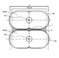
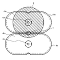
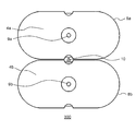
- Embodiment 1 of this invention It is a disassembled perspective view of the induction heating cooking appliance in Embodiment 1 of this invention. It is the top view which looked at the heating coil group of the induction heating cooking appliance in Embodiment 1 of this invention from the top. It is a figure which shows the example at the time of the heating by the single heating coil of the induction heating cooking appliance in Embodiment 1 of this invention. It is a figure which shows the example at the time of the heating in the multiple heating coil of the induction heating cooking appliance in Embodiment 1 of this invention. It is the top view which looked at the heating coil group of the induction heating cooking appliance in Embodiment 2 of this invention from the top.
- FIG. 1 is an exploded perspective view of induction heating cooker 100 according to Embodiment 1 of the present invention.
- a pan 2 which is an example of an object to be heated is arranged on the upper surface of the main body 1 of the induction heating cooker 100 in the present embodiment.
- the heating power is operated in the operation area 1a arranged in front of the main body 1, and the pan 2 is heated to perform cooking.
- the main body 1 of the induction heating cooker 100 includes a unit having a top plate 3, a heating coil unit 4, and a control unit 5.
- the top plate 3 is made of heat-resistant tempered glass, and a heating port 1b indicating an area where the user can heat the pan 2 is printed on the surface.
- heating coils 4a and 4b constituting the heating coil unit 4 are provided below the heating port 1b.
- a control unit 5 for controlling the high-frequency current supplied to the heating coils 4a and 4b is provided.
- the control unit 5 can switch the number of heating coils to be operated according to the size and position of the pan 2 which is an example of the object to be heated. For example, as shown in FIG.
- FIG. 2 is a view of the heating coil group of induction heating cooker 100 according to the embodiment of the present invention as viewed from above.
- the heating coils 4a and 4b are provided with first temperature sensors 6a and 6b in the vicinity of the center, respectively.
- the heating coil 4a and the heating coil 4b are arranged substantially on the same plane.
- the heating coil 4a and the heating coil 4b are configured by twisting a copper wire whose surface is coated with polyethylene or the like and winding it in an elliptical shape.
- the configuration in which the heating coils are arranged substantially on the same plane is illustrated. However, for the purpose of heating the same top plate, for example, coils having different thicknesses are arranged.
- the heating coils 4a and 4b are made of coated copper wires, but may be made of wires made of a plurality of layers such as copper and aluminum. It is not limited to the wire exemplified in.
- the heating coils 4a and 4b have shown the example arrange
- the shape of a heating coil is a circle, a polygon, a rectangle, a triangle, etc. There is no limitation as long as they are arranged in a line. Further, the number of heating coils is not limited to two, and three or more heating coils may be arranged.
- a second temperature sensor 7 is provided between the heating coil 4a and the heating coil 4b in the vicinity of the closest part of the heating coil 4a and the heating coil 4b.
- the second temperature sensor 7 is placed on the center line passing through the center of each heating coil, but it is not necessarily on the center line.
- the vicinity of the closest part is the major axis from the elliptical center of each adjacent heating coil as shown as a range X in FIG. Is preferably in the range of 90%, more preferably in the range of 80% of the major axis.
- the circular and rectangular heating coils it is preferable that they are within the range of 90% of the heating coil width in the direction perpendicular to the direction in which the heating coils are arranged from the center of the heating coil. More preferably, it is within the range.
- mica sheets 8a and 8b for heat insulation from the top plate 3 and insulation between the heating coils 4a and 4b are respectively provided.
- Each of the mica sheets 8a and 8b is provided with a hole so as to avoid the first temperature sensors 6a and 6b, and a notch so as to avoid the second temperature sensor 7 (for example, FIG. 2). reference).
- the case where the pan 2 is placed on the heating coil 4a and the heating coil 4a operates alone will be described.
- the heating coil 4a is used alone, the bottom temperature of the pan 2 is higher at the center because it is not affected by heat radiation to the surroundings. Therefore, the temperature of the pan bottom of the heated pan 2 is mainly detected by the first temperature sensor 6a, and the first temperature sensor 6a detects the temperature before abnormal heating, and the heating output is reduced or operated. It is possible to stop.
- Embodiment 2 In induction heating cooker 200 according to Embodiment 2 of the present invention, another configuration example of the first temperature sensor and the second temperature sensor will be described.
- the same components as those of the first embodiment of the present invention described above are denoted by the same reference numerals, and description thereof is omitted.
- FIG. 5 is a view of the heating coil group of induction heating cooker 200 according to the second embodiment of the present invention as viewed from above.
- the present embodiment is different from the first embodiment in that contact-type temperature sensors 9a, 9b, 9c that contact the top plate 3, such as thermistors, are used for the first temperature sensor and the second sensor. Is a point.
- the contact-type temperature sensors 9a, 9b, and 9c used as the first temperature sensor and the second temperature sensor detect the temperature rise of the top plate 3 and thus have the same effects as those described in the first embodiment. The effect of can be obtained.
- Embodiment 3 Induction heating cooker 300 according to Embodiment 3 of the present invention will be described below with reference to FIG. Note that the same components as those in the first and second embodiments of the present invention described above are denoted by the same reference numerals and description thereof is omitted.
- FIG. 6 is a view of the heating coil group of induction heating cooker 300 according to Embodiment 3 of the present invention as viewed from above.
- the difference from Embodiments 1 and 2 is that contact temperature sensors 9a and 9b that contact the top plate 3 are used for the first temperature sensor, and an example of an object to be heated is used for the second temperature sensor.
- the infrared sensor 10 which detects the infrared rays emitted from the pan 2 is used.
- the contact temperature sensors 9a and 9b are used for the first temperature sensor and the infrared sensor 10 is used for the second temperature sensor, the magnetic force is most concentrated and the temperature rise of the object to be heated is large.
- the temperature in the range X (see FIG. 2) during simultaneous heating of the plurality of heating coils can be detected quickly and accurately.
- the contact-type temperature sensors 9a and 9b are used as the first sensor, for example, when the position where the pan 2 is placed is greatly deviated from the heating port 1b, or when the infrared sensor 10 is out of the light receiving range.
- the contact-type temperature sensors 9a and 9b can sense the heat transmitted by heat conduction through the top plate 3. That is, the dielectric heating cooker 300 according to the present embodiment has the advantage that the temperature can be detected quickly and accurately by the infrared sensor 10, and the pot that is an example of the object to be heated immediately above the contact temperature sensors 9a and 9b. 2 has both of the advantages of being able to detect temperature even without two. Thereby, since the temperature of a to-be-heated material and the top plate 3 can be detected more rapidly and accurately, safety can be further improved.
- the configuration examples of the first temperature sensor and the second temperature sensor are shown.
- an infrared sensor is used as the first sensor
- a contact type is used as the second sensor.
- the configuration may be such that a temperature sensor is used, and is not limited to the configuration shown in the above-described embodiment.
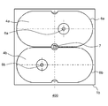
- FIG. 7 is a plan view of the heating coil group of induction heating cooker 400 according to Embodiment 4 of the present invention as viewed from above.
- FIG. 1 to 6 show an example in which the first temperature sensors 6a and 6b are arranged at the centers of the heating coils 4a and 4b.
- the first temperature sensors 6a and 6b are arranged as shown in FIG.
- the heating coils 4a and 4b may be arranged so as to be shifted from the center.
- the first temperature sensor 6a or the first temperature sensor is also provided when the pan 2 as the object to be heated is placed out of the center in the left-right direction of the heating port 1b as the heating area. Since either one of 6b is arranged close to the object to be heated, it is possible to accurately detect the temperature.
- FIG. 8 is a plan view of the heating coil group of induction heating cooker 500 in the present embodiment as viewed from above.
- the center of the heating coil does not necessarily have to be on the center line in the left-right direction or front-rear direction (up-down direction on the paper surface of FIG. 8) of heating opening 1b, which is a heating area.
- the induction heating cooker 500 is configured such that the first temperature sensors 6a and 6b are arranged so as to be shifted from the center line Y in the left-right direction of the heating port 1b.
- the center of the heating coils 4a, 4b may be on the center line in the left-right direction or the front-rear direction of the heating port 1b, and may not be on the center line.
- the object to be heated when the object to be heated is heated by a single heating coil, it is provided near the center of the heating coil that can raise the temperature of the object to be heated most. Control using both the temperature sensor and the temperature sensor provided near the location where the heated object is heated to the highest temperature when the object to be heated is heated with multiple heating coils. By doing, the induction heating cooking appliance by which safety was improved significantly can be provided.
- the present invention can accurately detect the temperature of the portion where the magnetic force is concentrated and becomes high temperature, and the user can select a place for heating the object to be heated.
- a cooking device having improved safety and cooking performance is provided. Therefore, it can utilize widely for uses, such as a cooking appliance for home use and business.
Landscapes
- Physics & Mathematics (AREA)
- Electromagnetism (AREA)
- Induction Heating Cooking Devices (AREA)
Abstract
Description
図1は、本発明の実施の形態1の誘導加熱調理器100の分解斜視図である。
本発明の実施の形態2における誘導加熱調理器200では、第1の温度センサおよび第2の温度センサの別の構成例を説明する。なお、上述した本発明の実施の形態1と同一構成要素については同一符号を付して、その説明を省略する。
本発明の実施の形態3の誘導加熱調理器300について、以下図6を用いて説明する。なお、上述した本発明の実施の形態1および実施の形態2と同一構成要素については、同一符号を付して、その説明を省略する。
本発明の実施の形態4における誘導加熱調理器400では、加熱コイルおよび第1の温度センサの位置関係の一例について、図7を用いて説明する。なお、上述した本発明の実施の形態1~実施の形態3と同一構成要素については同一符号を付して、その説明を省略する。
本発明の実施の形態5における誘導加熱調理器500では、加熱口および第1の温度センサの位置関係の別の例について、図8を用いて説明する。なお、上述した本発明の実施の形態1~実施の形態4と同一構成要素については、同一符号を付して、その説明を省略する。
1a 操作エリア
1b 加熱口
2 鍋(被加熱物)
3 トッププレート
4 加熱コイル部
4a,4b 加熱コイル
5 制御部
6a,6b 第1の温度センサ
7 第2の温度センサ
8a,8b マイカシート
9a,9b,9c 接触式温度センサ
10 赤外線センサ
Claims (5)
- 本体の上面に配設され被加熱物が載置されるトッププレートと、
前記トッププレートに形成され、前記被加熱物の載置エリアを示す加熱口と、
前記加熱口に対応して前記トッププレートの下方に配置され、複数の加熱コイルを有する加熱コイル部と、
前記加熱コイル部において前記被加熱物の大きさおよび載置位置に応じて、動作させる前記加熱コイルの個数を切り替えるとともに、動作させる前記加熱コイル部に供給する高周波電流を制御する制御部とを備え、
前記加熱コイル部は、前記複数の加熱コイルのうち少なくとも2つが並べられて配置されるとともに、
前記複数の加熱コイルそれぞれの中央近傍に設けられた第1の温度センサ、および、前記少なくとも2つの加熱コイルが互いに最も接近する箇所近傍の、前記少なくとも2つの加熱コイル間に設けられた第2の温度センサを有し、
前記制御部は、前記第1の温度センサおよび前記第2の温度センサで前記被加熱物の温度を検知して前記複数の加熱コイルの加熱を制御するよう構成された誘導加熱調理器。 - 前記第1の温度センサおよび前記第2の温度センサに、前記トッププレートに当接する接触式温度センサが用いられた請求項1に記載の誘導加熱調理器。
- 前記第1の温度センサは、前記トッププレートに当接する接触式温度センサで構成され、前記第2の温度センサは、前記被加熱物から放射される赤外線を検知する赤外線センサで構成された請求項1に記載の誘導加熱調理器。
- 前記第1の温度センサのうち少なくとも1つは、前記複数の加熱コイルのうち、前記第1の温度センサが設けられている加熱コイルの中心からずらして配置されている請求項1~3のいずれか1項に記載の誘導加熱調理器。
- 前記第1の温度センサのうち少なくとも1つは、前記加熱口の左右方向または前後方向における中心線からずらして配置された請求項1~4のいずれかに記載の誘導加熱調理器。
Priority Applications (2)
| Application Number | Priority Date | Filing Date | Title |
|---|---|---|---|
| EP16792378.8A EP3297399B1 (en) | 2015-05-13 | 2016-05-11 | Induction heating cooking device |
| JP2017517614A JP6883734B2 (ja) | 2015-05-13 | 2016-05-11 | 誘導加熱調理器 |
Applications Claiming Priority (2)
| Application Number | Priority Date | Filing Date | Title |
|---|---|---|---|
| JP2015097802 | 2015-05-13 | ||
| JP2015-097802 | 2015-05-13 |
Publications (1)
| Publication Number | Publication Date |
|---|---|
| WO2016181649A1 true WO2016181649A1 (ja) | 2016-11-17 |
Family
ID=57249194
Family Applications (1)
| Application Number | Title | Priority Date | Filing Date |
|---|---|---|---|
| PCT/JP2016/002303 Ceased WO2016181649A1 (ja) | 2015-05-13 | 2016-05-11 | 誘導加熱調理器 |
Country Status (3)
| Country | Link |
|---|---|
| EP (1) | EP3297399B1 (ja) |
| JP (1) | JP6883734B2 (ja) |
| WO (1) | WO2016181649A1 (ja) |
Cited By (2)
| Publication number | Priority date | Publication date | Assignee | Title |
|---|---|---|---|---|
| JP2020057470A (ja) * | 2018-09-28 | 2020-04-09 | 三菱電機株式会社 | 加熱調理器 |
| US20200383512A1 (en) * | 2017-12-07 | 2020-12-10 | Mitsubishi Electric Corporation | Induction heating cooker |
Citations (3)
| Publication number | Priority date | Publication date | Assignee | Title |
|---|---|---|---|---|
| JP2011009079A (ja) * | 2009-06-25 | 2011-01-13 | Panasonic Electric Works Co Ltd | コンロ装置及びコンロ付き調理台装置 |
| JP2013054951A (ja) * | 2011-09-05 | 2013-03-21 | Mitsubishi Electric Corp | 誘導加熱調理器 |
| JP2013069670A (ja) * | 2012-06-27 | 2013-04-18 | Mitsubishi Electric Corp | 誘導加熱調理器 |
Family Cites Families (6)
| Publication number | Priority date | Publication date | Assignee | Title |
|---|---|---|---|---|
| JP5202064B2 (ja) * | 2008-03-27 | 2013-06-05 | 三菱電機株式会社 | 誘導加熱調理器 |
| EP2408262B1 (en) * | 2009-03-13 | 2019-06-05 | Panasonic Corporation | Induction heating cooking device and kitchen apparatus |
| JP5279620B2 (ja) * | 2009-06-03 | 2013-09-04 | 三菱電機株式会社 | 誘導加熱調理器 |
| EP2813129B1 (de) * | 2012-02-10 | 2019-03-13 | BSH Hausgeräte GmbH | Induktionskochfeld mit induktorspulen-feld |
| EP2670211A3 (de) * | 2012-05-31 | 2014-08-13 | BSH Bosch und Siemens Hausgeräte GmbH | Kochfeldvorrichtung |
| CN104221470B (zh) * | 2012-10-22 | 2016-08-24 | 松下电器产业株式会社 | 感应加热烹调器 |
-
2016
- 2016-05-11 EP EP16792378.8A patent/EP3297399B1/en active Active
- 2016-05-11 JP JP2017517614A patent/JP6883734B2/ja active Active
- 2016-05-11 WO PCT/JP2016/002303 patent/WO2016181649A1/ja not_active Ceased
Patent Citations (3)
| Publication number | Priority date | Publication date | Assignee | Title |
|---|---|---|---|---|
| JP2011009079A (ja) * | 2009-06-25 | 2011-01-13 | Panasonic Electric Works Co Ltd | コンロ装置及びコンロ付き調理台装置 |
| JP2013054951A (ja) * | 2011-09-05 | 2013-03-21 | Mitsubishi Electric Corp | 誘導加熱調理器 |
| JP2013069670A (ja) * | 2012-06-27 | 2013-04-18 | Mitsubishi Electric Corp | 誘導加熱調理器 |
Cited By (4)
| Publication number | Priority date | Publication date | Assignee | Title |
|---|---|---|---|---|
| US20200383512A1 (en) * | 2017-12-07 | 2020-12-10 | Mitsubishi Electric Corporation | Induction heating cooker |
| US11503939B2 (en) * | 2017-12-07 | 2022-11-22 | Mitsubishi Electric Corporation | Induction heating cooker |
| JP2020057470A (ja) * | 2018-09-28 | 2020-04-09 | 三菱電機株式会社 | 加熱調理器 |
| JP7129868B2 (ja) | 2018-09-28 | 2022-09-02 | 三菱電機株式会社 | 加熱調理器 |
Also Published As
| Publication number | Publication date |
|---|---|
| JP6883734B2 (ja) | 2021-06-09 |
| JPWO2016181649A1 (ja) | 2018-02-22 |
| EP3297399B1 (en) | 2021-03-17 |
| EP3297399A4 (en) | 2018-06-20 |
| EP3297399A1 (en) | 2018-03-21 |
Similar Documents
| Publication | Publication Date | Title |
|---|---|---|
| US11655984B2 (en) | Induction cooktop | |
| JP5699185B2 (ja) | 拡大した加熱範囲を有する電磁誘導加熱器 | |
| JP2010073384A (ja) | 誘導加熱調理器 | |
| JP7229022B2 (ja) | 誘導加熱調理器 | |
| JP6883734B2 (ja) | 誘導加熱調理器 | |
| JP2009048867A (ja) | 加熱調理器 | |
| WO2018042941A1 (ja) | 誘導加熱調理器 | |
| JP6991309B2 (ja) | 誘導加熱調理器 | |
| JP2007287536A (ja) | 誘導加熱調理器 | |
| JP6749211B2 (ja) | 誘導加熱調理器 | |
| JP2006079916A (ja) | 誘導加熱調理器 | |
| JP5142856B2 (ja) | 誘導加熱調理器 | |
| JP7138457B2 (ja) | 誘導加熱調理器 | |
| JP4941097B2 (ja) | 誘導加熱調理器 | |
| JP2013054951A (ja) | 誘導加熱調理器 | |
| JP5325040B2 (ja) | コンロ装置及びコンロ付き調理台装置 | |
| US11284480B2 (en) | Sensor holding tray fixing | |
| JP7129868B2 (ja) | 加熱調理器 | |
| JP2012209101A (ja) | 誘導加熱調理器 | |
| JP5389114B2 (ja) | 誘導加熱調理器 | |
| JP2018190583A (ja) | 誘導加熱調理器 | |
| JP6452527B2 (ja) | 誘導加熱調理器 | |
| KR101813279B1 (ko) | 전기 호브 | |
| CN217088201U (zh) | 一种组合式加热结构 | |
| JP2006031947A (ja) | 電磁誘導加熱調理器 |
Legal Events
| Date | Code | Title | Description |
|---|---|---|---|
| 121 | Ep: the epo has been informed by wipo that ep was designated in this application |
Ref document number: 16792378 Country of ref document: EP Kind code of ref document: A1 |
|
| ENP | Entry into the national phase |
Ref document number: 2017517614 Country of ref document: JP Kind code of ref document: A |
|
| REEP | Request for entry into the european phase |
Ref document number: 2016792378 Country of ref document: EP |
|
| WWE | Wipo information: entry into national phase |
Ref document number: 2016792378 Country of ref document: EP |
|
| NENP | Non-entry into the national phase |
Ref country code: DE |