WO2016181826A1 - 薬剤投与具およびプレフィルドシリンジ - Google Patents
薬剤投与具およびプレフィルドシリンジ Download PDFInfo
- Publication number
- WO2016181826A1 WO2016181826A1 PCT/JP2016/063059 JP2016063059W WO2016181826A1 WO 2016181826 A1 WO2016181826 A1 WO 2016181826A1 JP 2016063059 W JP2016063059 W JP 2016063059W WO 2016181826 A1 WO2016181826 A1 WO 2016181826A1
- Authority
- WO
- WIPO (PCT)
- Prior art keywords
- injection needle
- nozzle
- prefilled syringe
- drug
- opening
- Prior art date
- Legal status (The legal status is an assumption and is not a legal conclusion. Google has not performed a legal analysis and makes no representation as to the accuracy of the status listed.)
- Ceased
Links
Images


Classifications
-
- A—HUMAN NECESSITIES
- A61—MEDICAL OR VETERINARY SCIENCE; HYGIENE
- A61J—CONTAINERS SPECIALLY ADAPTED FOR MEDICAL OR PHARMACEUTICAL PURPOSES; DEVICES OR METHODS SPECIALLY ADAPTED FOR BRINGING PHARMACEUTICAL PRODUCTS INTO PARTICULAR PHYSICAL OR ADMINISTERING FORMS; DEVICES FOR ADMINISTERING FOOD OR MEDICINES ORALLY; BABY COMFORTERS; DEVICES FOR RECEIVING SPITTLE
- A61J1/00—Containers specially adapted for medical or pharmaceutical purposes
- A61J1/14—Details; Accessories therefor
- A61J1/20—Arrangements for transferring or mixing fluids, e.g. from vial to syringe
- A61J1/2096—Combination of a vial and a syringe for transferring or mixing their contents
-
- A—HUMAN NECESSITIES
- A61—MEDICAL OR VETERINARY SCIENCE; HYGIENE
- A61M—DEVICES FOR INTRODUCING MEDIA INTO, OR ONTO, THE BODY; DEVICES FOR TRANSDUCING BODY MEDIA OR FOR TAKING MEDIA FROM THE BODY; DEVICES FOR PRODUCING OR ENDING SLEEP OR STUPOR
- A61M5/00—Devices for bringing media into the body in a subcutaneous, intra-vascular or intramuscular way; Accessories therefor, e.g. filling or cleaning devices, arm-rests
- A61M5/178—Syringes
- A61M5/31—Details
- A61M5/32—Needles; Details of needles pertaining to their connection with syringe or hub; Accessories for bringing the needle into, or holding the needle on, the body; Devices for protection of needles
- A61M5/34—Constructions for connecting the needle, e.g. to syringe nozzle or needle hub
-
- A—HUMAN NECESSITIES
- A61—MEDICAL OR VETERINARY SCIENCE; HYGIENE
- A61M—DEVICES FOR INTRODUCING MEDIA INTO, OR ONTO, THE BODY; DEVICES FOR TRANSDUCING BODY MEDIA OR FOR TAKING MEDIA FROM THE BODY; DEVICES FOR PRODUCING OR ENDING SLEEP OR STUPOR
- A61M5/00—Devices for bringing media into the body in a subcutaneous, intra-vascular or intramuscular way; Accessories therefor, e.g. filling or cleaning devices, arm-rests
- A61M5/178—Syringes
- A61M5/28—Syringe ampoules or carpules, i.e. ampoules or carpules provided with a needle
-
- A—HUMAN NECESSITIES
- A61—MEDICAL OR VETERINARY SCIENCE; HYGIENE
- A61M—DEVICES FOR INTRODUCING MEDIA INTO, OR ONTO, THE BODY; DEVICES FOR TRANSDUCING BODY MEDIA OR FOR TAKING MEDIA FROM THE BODY; DEVICES FOR PRODUCING OR ENDING SLEEP OR STUPOR
- A61M5/00—Devices for bringing media into the body in a subcutaneous, intra-vascular or intramuscular way; Accessories therefor, e.g. filling or cleaning devices, arm-rests
- A61M5/178—Syringes
- A61M5/31—Details
- A61M5/32—Needles; Details of needles pertaining to their connection with syringe or hub; Accessories for bringing the needle into, or holding the needle on, the body; Devices for protection of needles
- A61M5/3202—Devices for protection of the needle before use, e.g. caps
-
- A—HUMAN NECESSITIES
- A61—MEDICAL OR VETERINARY SCIENCE; HYGIENE
- A61M—DEVICES FOR INTRODUCING MEDIA INTO, OR ONTO, THE BODY; DEVICES FOR TRANSDUCING BODY MEDIA OR FOR TAKING MEDIA FROM THE BODY; DEVICES FOR PRODUCING OR ENDING SLEEP OR STUPOR
- A61M5/00—Devices for bringing media into the body in a subcutaneous, intra-vascular or intramuscular way; Accessories therefor, e.g. filling or cleaning devices, arm-rests
- A61M5/178—Syringes
- A61M5/31—Details
- A61M5/32—Needles; Details of needles pertaining to their connection with syringe or hub; Accessories for bringing the needle into, or holding the needle on, the body; Devices for protection of needles
- A61M5/3287—Accessories for bringing the needle into the body; Automatic needle insertion
-
- A—HUMAN NECESSITIES
- A61—MEDICAL OR VETERINARY SCIENCE; HYGIENE
- A61J—CONTAINERS SPECIALLY ADAPTED FOR MEDICAL OR PHARMACEUTICAL PURPOSES; DEVICES OR METHODS SPECIALLY ADAPTED FOR BRINGING PHARMACEUTICAL PRODUCTS INTO PARTICULAR PHYSICAL OR ADMINISTERING FORMS; DEVICES FOR ADMINISTERING FOOD OR MEDICINES ORALLY; BABY COMFORTERS; DEVICES FOR RECEIVING SPITTLE
- A61J1/00—Containers specially adapted for medical or pharmaceutical purposes
- A61J1/14—Details; Accessories therefor
- A61J1/20—Arrangements for transferring or mixing fluids, e.g. from vial to syringe
- A61J1/2003—Accessories used in combination with means for transfer or mixing of fluids, e.g. for activating fluid flow, separating fluids, filtering fluid or venting
- A61J1/2006—Piercing means
- A61J1/201—Piercing means having one piercing end
-
- A—HUMAN NECESSITIES
- A61—MEDICAL OR VETERINARY SCIENCE; HYGIENE
- A61M—DEVICES FOR INTRODUCING MEDIA INTO, OR ONTO, THE BODY; DEVICES FOR TRANSDUCING BODY MEDIA OR FOR TAKING MEDIA FROM THE BODY; DEVICES FOR PRODUCING OR ENDING SLEEP OR STUPOR
- A61M5/00—Devices for bringing media into the body in a subcutaneous, intra-vascular or intramuscular way; Accessories therefor, e.g. filling or cleaning devices, arm-rests
- A61M5/178—Syringes
- A61M5/20—Automatic syringes, e.g. with automatically actuated piston rod, with automatic needle injection, filling automatically
- A61M5/2033—Spring-loaded one-shot injectors with or without automatic needle insertion
Definitions
- the present invention relates to a drug administration device and a prefilled syringe that are provided with an injection needle and administer the drug.
- a drug container such as a vial containing a dry drug
- a medical container such as a prefilled syringe filled with distilled water, physiological saline, glucose solution, etc.
- a solution is injected to dissolve the dry drug in the solution.
- a connector is used to connect the inside of the drug container and the prefilled syringe.
- the medicine prepared in the medicine container is filled into the prefilled syringe through the connecting device.
- the drug can be administered to a patient or the like.
- Patent Document 1 Japanese Patent Application Laid-Open No. 2011-19704 (Patent Document 1) and Japanese Patent Application Laid-Open No. 2014-79331 (Patent Document 2).
- Patent Literatures 1 and 2 are provided on one end side, a medicine container insertion portion into which a mouth portion of the medicine container is inserted, and provided on the other end side, and a tip of a prefilled syringe (syringe) is provided.
- the needle on the other end of the double-ended needles While inserting the drug container into the drug container insertion part and pushing the prefilled syringe toward the drug container side with the prefilled syringe inserted into the syringe insertion part, the needle on the other end of the double-ended needles The lid member is penetrated. Subsequently, the sealing member is penetrated by the needle on one end side of the double-ended needles by pushing the prefilled syringe and the connecting device toward the drug container side.
- the syringe insertion portion is provided with a locking portion that locks the lid member of the prefilled syringe, and the locking portion locks the lid member when the prefilled syringe is removed from the syringe insertion portion.
- the injection needle can be attached to the tip of the prefilled syringe by removing the prefilled syringe from the connecting device with the lid member removed.
- Patent Documents 1 and 2 Drug administration devices have been developed that can prevent erroneous connection of the injection needle using a connecting device different from the configuration of Patent Documents 1 and 2.
- a document disclosing such a drug administration device for example, JP 2011-72440 A (Patent Document 3) can be cited.
- the drug administration device disclosed in Patent Document 3 includes a prefilled syringe, a connecting device, and a drug container.
- the tip of the prefilled syringe is configured so that an injection needle cannot be attached.
- the connector is configured such that the inner side is configured so that the tip of a prefilled syringe can be inserted, and the outer side is configured so that an injection needle can be attached, and the connector is provided on one end side, and the connector member is detachably connected.
- a guide member provided on the other end side and having a drug container insertion portion into which a mouth portion of the drug container is inserted.
- the tip of the prefilled syringe is connected to the connector member inserted in the connector member insertion portion, and the prefilled syringe is pushed toward the drug container, whereby the puncture member moves in the guide member.
- the puncture needle By moving the puncture member, the puncture needle can be passed through the sealing member that seals the mouth of the drug container.
- the puncture member and the guide member are engaged in a state where the puncture needle penetrates the sealing member, and the detachment of the puncture member from the guide member is suppressed.
- the connector member is detachably fitted to the puncture member.
- the connector disclosed in Patent Documents 1 and 2 includes an inner cylinder member and an outer cylinder member.
- the outer cylinder member is used. It is the structure made to slide to the outer side of an inner cylinder member.
- the connecting device is configured to push the inner cylinder member into the drug container when the needle on the other end side of the double-ended needle is passed through the sealing member of the drug container. For this reason, in the connection instrument disclosed in Patent Documents 1 and 2, the configuration is complicated.
- the present invention has been made in view of the above problems, and an object of the present invention is to prevent an injection needle from being erroneously attached to a prefilled syringe before drug preparation while having a simple configuration.
- the object is to provide a drug administration device and a prefilled syringe.
- a drug administration device includes a drug container that stores a drug in a sealed interior, a nozzle portion provided on a distal end side, and a cylindrical injection needle mounting portion that surrounds the nozzle portion and to which a syringe needle is mounted.
- the coupling device partitions the inside of the cylindrical body into the receiving part side and the insertion part side, and a partition part having a through hole in the center part, A cylindrical nozzle insertion portion that is provided on the receiving portion side so as to communicate with the through-hole, and that is inserted between the nozzle portion and the injection needle mounting portion so that the nozzle portion is liquid-tightly inserted;
- the prefilled syringe further detachably fits on the outer peripheral side of the injection needle mounting portion and further includes a cap member having an opening, and an injection needle is provided on the inner peripheral surface of the injection needle mounting portion.
- a guide groove that engages with an engagement protrusion provided at the base end of the needle and guides the movement of the injection needle is provided, and the opening is provided so that the nozzle insertion portion can be inserted, and the base end of the injection needle Is provided so that it cannot be inserted.
- Member in a state that fitted on the outer peripheral side of the needle mounting portion, at least a part of the edge of the opening when viewed in the axial direction of the nozzle portion is located inside the bottom of the guide groove.
- the opening preferably has a circular shape, and the guide groove is preferably formed by a spiral groove.
- the inner diameter of the opening is preferably smaller than the valley diameter of the spiral groove.
- the cap member is removed from the injection needle mounting portion when the prefilled syringe is removed from the connector.
- the cylinder has a locking piece provided on the inner surface of the cylinder located on the receiving portion side.
- the locking piece preferably locks the cap member when the prefilled syringe is removed from the coupling device.
- the length of the cap member along the axial direction of the nozzle portion is preferably shorter than the length of the injection needle mounting portion along the axial direction.
- the locking piece preferably locks the end portion on the proximal end side of the cap member.
- a prefilled syringe includes a nozzle part provided at a distal end part and a cylindrical container having a cylindrical injection needle attachment part surrounding the nozzle part to which an injection needle is attached, and a proximal end side of the cylindrical container.
- a guide groove that engages with the provided engagement protrusion and guides the movement of the injection needle is provided, and the opening can be inserted with a plug member that seals the nozzle portion in a liquid-tight manner, and the injection needle
- the base end portion is provided so as not to be inserted, and the cap member is fitted on the outer peripheral side of the injection needle mounting portion, at least a part of the edge of the opening portion is viewed from the axial direction of the nozzle portion.
- the opening preferably has a circular shape, and the guide groove is preferably constituted by a spiral groove.
- the inner diameter of the opening is preferably smaller than the valley diameter of the spiral groove.
- a drug administration device and a prefilled syringe that have a simple configuration and prevent an injection needle from being erroneously attached to a prefilled syringe before drug preparation.
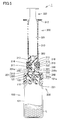
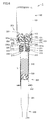
- FIG. 1 is a cross-sectional view showing components of a drug administration device according to an embodiment of the present invention. With reference to FIG. 1, the drug administration device according to the present embodiment will be described.
- the drug administration device 1 includes a drug container 100, a connecting device 200, and a prefilled syringe 300.
- the drug container 100 contains a dry drug or a liquid drug as a drug inside.
- the medicine container 100 includes a container main body 101 having a mouth portion 101a and a sealing member 110 that seals the mouth portion 101a.
- the sealing member 110 is fixed to the tip of the drug container 100 by the ring-shaped member 120.
- the sealing member 110 can employ a rubber member or a thermoplastic elastomer resin.
- the central part of the sealing member 110 is formed in a thin shape.
- a puncture needle 250 of the connecting device 200 described later can be pierced through the central portion of the sealing member 110.
- the ring-shaped member 120 surrounds the distal end portion of the container main body 101 and the sealing member 110 from the outer peripheral side, and fastens them together.
- the ring-shaped member 120 has an opening 121 that exposes the central portion of the sealing member 110.
- the connecting device 200 is for communicating the inside of the medicine container 100 with the inside of the prefilled syringe 300.
- the connecting device 200 includes a cylindrical body 201, a partition part 230, a nozzle insertion part 240 and a puncture needle 250.
- the cylindrical body 201 has a receiving portion 200a for receiving a nozzle portion 311 and an injection needle mounting portion 313 of a prefilled syringe 300, which will be described later, on one end 201a side, and an insertion portion 200b that can be attached to the drug container 100 on the other end 201b side.
- a receiving portion 200a for receiving a nozzle portion 311 and an injection needle mounting portion 313 of a prefilled syringe 300, which will be described later, on one end 201a side, and an insertion portion 200b that can be attached to the drug container 100 on the other end 201b side.
- the cylindrical body 201 is composed of a first cylindrical portion 210 and a second cylindrical portion 220.
- the 1st cylinder part 210 and the 2nd cylinder part 220 have a common central axis.
- the 1st cylinder part 210 and the 2nd cylinder part 220 are integrally shape
- a protruding portion 213 and a locking piece 215 are provided on one end side of the first tube portion 210.
- the protruding portion 213 is provided on the outer peripheral surface 212 of the first tube portion 210.
- the protruding portion 213 protrudes radially outward from the outer peripheral surface of the first tube portion 210.
- the protruding portion 213 engages with a spiral groove 316 of a connecting device mounting portion 315 provided in a prefilled syringe 300 described later.
- the locking piece 215 is provided on the inner peripheral surface 211 of the first cylindrical portion 210.
- the locking piece 215 is directed radially inward of the cylindrical body 201 as it approaches the partition portion 230.
- a plurality of locking pieces 215 are provided at a 90 ° pitch in the circumferential direction.
- the locking piece 215 is a part for locking and removing a cap member 330 described later when the prefilled syringe 300 is removed from the connecting device 200.
- the second cylinder part 220 is provided so as to be insertable into the mouth part 101a of the medicine container 100.
- the internal diameter of the 2nd cylinder part 220 is provided slightly smaller than the opening part 101a. In a state where the second cylinder part 220 is inserted into the mouth part 101a, the second cylinder part 220 is spread outward, and the inner peripheral surface 221 of the second cylinder part 220 sandwiches the outer periphery part of the mouth part 101a.
- the notch part 224 is provided in the 2nd cylinder part 220.
- FIG. By providing the notch portion 224, the second tube portion 220 is easily bent and deformed, and is easily inserted into the mouth portion 101a.
- the inner peripheral surface 221 of the second cylindrical portion 220 is slidably provided on the outer periphery of the mouth portion 101a. In a state where the second cylinder part 220 is inserted into the mouth part 101a, the cylinder body 201 can be pushed into the medicine container 100 side.
- the partition part 230 partitions the inside of the cylinder 201 into the receiving part 200a side and the insertion part 200b side.
- the partition part 230 has a disk shape.
- the partition part 230 has the through-hole 230a in the center part.
- the nozzle insertion part 240 is provided in the main surface 230b of the partition part 230 located in the one end 201a side.
- the nozzle insertion portion 240 extends from the main surface 230b toward the one end 201a of the cylindrical body 201.
- the nozzle insertion part 240 has a cylindrical shape.
- the inside of the nozzle insertion portion 240 communicates with the through hole 230a.
- the nozzle portion 311 of the prefilled syringe 300 is inserted into the nozzle insertion portion 240 in a liquid-tight manner.
- the puncture needle 250 is provided in the main surface 230c of the partition part 230 located in the other end 201b side.
- the puncture needle 250 extends from the main surface 230c toward the other end 201b of the cylindrical body 201.
- the puncture needle 250 has a hollow duct 250a communicating with the through hole 230a.
- the puncture needle 250 is provided so as to be able to penetrate the sealing member 110 described above.
- the receiving portion 200a for receiving the nozzle portion 311 and the injection needle mounting portion 313 is constituted by the first tubular portion 210, the partition portion 230, and the nozzle insertion portion 240 described above.
- the nozzle portion 311 is inserted into the nozzle insertion portion 240, and the injection needle attachment portion 313 is inserted into the gap between the nozzle insertion portion 240 and the first tube portion 210.
- the nozzle portion 311 fits into the nozzle insertion portion 240, and it becomes difficult for the nozzle portion 311 and the injection needle attachment portion 313 to be pushed toward the partition portion 230 side, so that the nozzle portion 311 and the injection needle attachment portion are inserted into the receiving portion 200a. 313 is accepted.
- the above-mentioned second cylinder part 220 constitutes an insertion part 200b that can be attached to the medicine container 100.
- the drug container 100 is inserted into the insertion part 200b.
- the prefilled syringe 300 includes a cylindrical container 310, a plunger 320, a cap member 330, and a plug member 340.
- the cylindrical container 310 includes a nozzle portion 311 provided on the distal end side, a flange portion 312 provided on the proximal end side, an injection needle attachment portion 313 provided outside the nozzle portion 311, and an outer side of the injection needle attachment portion 313. And a connecting device mounting portion 315 provided in the housing.
- the nozzle part 311 is provided so that the liquid agent accommodated in the cylindrical container 310 can be discharged.
- a solution or a chemical solution such as physiological saline or butter sugar solution can be adopted.
- the flange portion 312 protrudes from the proximal end of the cylindrical container 310 outward in the radial direction.
- the flange portion 312 is configured to be able to hook a fingertip such as an index finger and a middle finger.
- the injection needle mounting portion 313 is provided so as to surround the nozzle portion 311.
- the injection needle attachment portion 313 is a part for attaching an injection needle 400 (see FIG. 8) described later.
- the injection needle mounting portion 313 has a substantially cylindrical shape.
- a spiral groove 314 as a guide groove is provided on the inner peripheral surface of the injection needle mounting portion 313.
- the spiral groove 314 engages with an engagement protrusion 421 (see FIG. 8) provided at the proximal end of the injection needle 400. That is, a valley diameter L2 (see FIG. 2) of a spiral groove 314 described later is slightly larger than the outer diameter of the engagement protrusion 421.
- the valley diameter L2 of the spiral groove 314 is the distance between the bottoms of the spiral groove 314. The spiral groove 314 guides the movement of the injection needle 400 when the injection needle 400 is attached to the injection needle attachment portion 313.
- the connecting instrument mounting portion 315 is provided so as to surround the injection needle mounting portion 313.
- the connection tool attachment portion 315 is a part for attaching one end side of the connection tool 200.
- the connecting instrument mounting portion 315 has a substantially cylindrical shape.
- a spiral groove 316 is provided on the inner peripheral surface of the connecting device mounting portion 315.
- the spiral groove 316 engages with a protrusion 213 provided on one end side of the connecting device 200.
- the spiral groove 316 guides the movement of the connecting device 200 when the connecting device 200 is attached to the connecting device attaching portion 315.
- the plunger 320 is inserted from the proximal end side of the cylindrical container 310.
- the plunger 320 has a plunger rod 321 and a gasket 322 attached to the tip of the plunger rod 321.
- the gasket 322 is slidably provided on the inner peripheral surface of the cylindrical container 310. The gasket 322 maintains the inside of the cylindrical container 310 liquid-tight.
- the cap member 330 is detachably fitted to the outer peripheral side of the injection needle mounting portion 313.
- the cap member 330 has a top plate portion 331 and a peripheral wall portion 332.
- the top plate portion 331 has a disc shape.
- a circular opening 331a is provided at a substantially central portion of the top plate portion 331. When viewed from the axial direction of the nozzle portion 311, the opening 331 a exposes the nozzle portion 311.
- the peripheral wall portion 332 is formed in a cylindrical shape and is provided so as to be connected to the peripheral edge of the top plate portion 331.
- the opening 331a is provided so that the proximal end side of the injection needle 400 cannot be inserted. Specifically, the diameter L1 (see FIG. 2) of the opening 331a is smaller than the outer diameter of the engagement protrusion 421 of the injection needle 400. The aperture L1 of the opening 331a is smaller than the valley diameter L2 of the spiral groove 314.
- the cap member 330 can be attached to the injection needle mounting portion 313. In the state where the needle 400 is fitted, the attachment of the injection needle 400 to the injection needle attachment portion 313 is disabled. In addition, by making the diameter L1 of the opening 331a smaller than the inner diameter (distance between the crests) of the spiral groove 314, the attachment of the injection needle 400 to the injection needle attachment portion 313 can be more reliably disabled. .
- the plug member 340 is detachably attached to the nozzle portion 311.
- the plug member 340 is provided in a bottomed cylindrical shape.
- the plug member 340 is liquid-tightly sealed with the nozzle portion 311 while being attached to the nozzle portion 311.
- One end side of the plug member 340 located on the opposite side of the bottom portion facing the tip of the nozzle portion 311 is provided so as to be inserted into the opening 331a of the cap member 330.
- One end side of the plug member 340 enters a gap between the outer peripheral surface of the nozzle portion 311 and the inner peripheral surface of the injection needle attachment portion 313.
- the outer diameter on one end side of the plug member 340 is smaller than the diameter of the opening 331a. Further, the outer diameter on one end side of the plug member 340 is smaller than the inner diameter of the spiral groove 314.
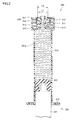
- FIG. 2 is a cross-sectional view showing a first step when using the drug administration device shown in FIG. 1, and is an enlarged view of the front end side of the prefilled syringe.
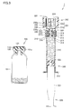
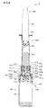
- 3 to 8 are cross-sectional views showing the second to seventh steps when using the drug administration device shown in FIG. With reference to FIG. 2 to FIG. 8, the operation when using the drug administration device 1 according to the present embodiment will be described.
- the drug container 100 in which the drug is sealed, the connecting device 200, and the prefilled syringe 300 in which the liquid drug is stored are prepared separately.
- the cap member 330 is fitted in the outer peripheral side of the injection needle attaching part 313, what the nozzle part 311 is sealed with the stopper member 340 is prepared.
- the plug member 340 is removed from the prefilled syringe 300 in the first step. At this time, it is preferable to remove the plug member 340 with the nozzle portion 311 facing upward so that the liquid agent does not leak outside from the nozzle portion 311.
- the connecting device 200 is attached to the tip of the prefilled syringe 300 with the nozzle portion 311 facing upward. Specifically, the projection 213 provided on the outer peripheral surface of the first tube portion 210 is engaged with the spiral groove 316 of the connection device mounting portion 315, and the connection device 200 is rotated around the axis of the tube body 201.
- the nozzle insertion portion 240 passes through the opening 331 a of the cap member 330 and the gap between the nozzle portion 311 and the injection needle attachment portion 313. Get in.
- the connecting tool 200 is advanced by a predetermined distance toward the prefilled syringe 300 along the axial direction of the cylindrical body 201.
- the nozzle portion 311 is inserted in a liquid-tight manner.
- the distance between the tip portions of the locking pieces 215 facing each other is smaller than the outer diameter of the peripheral wall portion 332 of the cap member 330. For this reason, when the connecting device 200 is advanced toward the prefilled syringe 300 along the axial direction of the cylindrical body 201, the locking piece 215 is pushed and spread by the cap member 330. After the entire cap member 330 has relatively passed through the locking piece 215, the locking piece 215 returns to its original shape. Thereby, the locking piece 215 can be locked to the proximal end side of the cap member 330.
- the connecting device 200 includes the inside of the cylindrical container 310 and the medicine in a state where the nozzle part 311 and the injection needle attachment part 313 are received in the receiving part 200a and the medicine container 100 is inserted in the insertion part 200b. The inside of the container 100 is communicated.
- the nozzle part 311 of the prefilled syringe 300 is directed downward, and the connecting instrument 200 is directed downward in a state where the drug container 100 is positioned below the second cylindrical part 220. It is preferable to push in.
- the plunger 320 is pushed toward the drug container 100, so that the liquid stored in the prefilled syringe 300 is discharged into the nozzle portion 311, the through-hole 230 a and the puncture needle. It moves to the inside of the medicine container 100 through the 250 hollow pipes 250a.
- the drug L is prepared by mixing the drug and the liquid in the drug container 100.
- the plunger 320 is moved upward of the cylindrical container 310 with the nozzle portion 311 facing upward.
- the drug L prepared in the drug container 100 is sucked into the prefilled syringe 300.
- the prefilled syringe 300 is removed from the connecting device 200. Specifically, the connecting device 200 is rotated around the axis of the cylinder 201 with the nozzle portion 311 facing upward. At this time, the connecting device 200 is rotated in the direction opposite to the rotation direction in the second step.
- the connecting device 200 moves in a direction away from the prefilled syringe 300 by relatively retracting the protrusion 213 along the spiral groove 316. At this time, the nozzle insertion portion 240 is separated from the nozzle portion 311 through the opening 331 a of the cap member 330. Thereby, the nozzle part 311 is extracted from the nozzle insertion part 240.
- the connecting device 200 moves in a direction away from the prefilled syringe 300, the locking piece 215 is locked to the proximal end of the cap member 330. For this reason, when the connecting device 200 moves, the injection needle mounting portion 313 moves backward relative to the cap member 330.
- the cap member 330 is removed from the syringe needle mounting portion 313 by the syringe needle mounting portion 313 moving backward relative to the cap member 330 by a predetermined distance.
- the removed cap member 330 is accommodated in a gap between the nozzle insertion portion 240 and the first tube portion 210.
- the prefilled syringe 300 is removed from the connecting device 200 in a state where the cap member 330 is removed from the injection needle mounting portion 313.
- the injection needle 400 can be attached to the injection needle attachment portion 313.
- the injection needle 400 is attached to the injection needle attachment portion 313.
- the injection needle 400 includes a needle tube 410 and a needle base 420.
- the proximal end of the needle base 420 has an engaging protrusion 421 that protrudes radially outward.
- the engagement protrusion 421 is provided so as to be engageable with the spiral groove 314 of the injection needle mounting portion 313.
- the injection needle 400 By engaging the engagement protrusion 421 with the spiral groove 314 and rotating the injection needle 400 around the axis, the injection needle 400 can be attached to the injection needle attachment portion 313.
- the injection needle 400 is attached to the injection needle attachment portion 313.
- the cap member 330 includes a top plate portion 331 having an opening 331 a at the center portion, and a cylindrical peripheral wall portion 332 connected to the periphery of the top plate portion 331. For this reason, the configuration of the cap member 330 can be simplified, and as a result, the configuration of the drug administration device 1 can be simplified.
- the inside of the medicine container 100 and the inside of the prefilled syringe 300 are connected using the connecting device 200, and the medicine in the medicine container 100 and the liquid medicine in the prefilled syringe 300 are mixed. Until the preparation of the medicine L is completed, the state where the cap member 330 is attached to the injection needle attaching portion 313 is maintained.
- the cap member 330 can be removed from the injection needle mounting portion 313, so that the user is prevented from accidentally attaching the injection needle 400 to the injection needle mounting portion 313 before the preparation of the medicine. can do.
- the user must sequentially perform the operations from the first step to the sixth step until the cap member 330 is removed, and attaches the injection needle while being aware of the procedure. This can also prevent the injection needle 400 from being erroneously attached to the injection needle attachment portion 313 before the preparation of the medicine L.
- the cap member 330 is locked by the locking piece 215 and the prefilled syringe 300 is removed from the connecting device 200, the cap member 330 is removed from the injection needle mounting portion 313, so that the user directly holds the cap member 330. It becomes unnecessary to remove. Thereby, it becomes possible to save a user's effort.
- the connecting device 200 has a configuration in which a cylindrical body 201 constituted by a first cylindrical portion 210 and a second cylindrical portion 220 is divided into two in the axial direction by a partitioning portion 230.
- the connecting device 200 has a configuration in which a cylindrical nozzle insertion portion 240 is provided on the first cylindrical portion 210 side and a puncture needle is provided on the second cylindrical portion 220 side.
- the connecting device 200 By configuring the connecting device 200 in this manner, the prefilled syringe 300 is inserted into the first tube portion 210 side, and the drug container 100 is inserted into the second tube portion 220 side, and then the tube body 201 is inserted into the drug container 100. By pushing inward, the puncture needle can be pierced through the sealing member 110 of the drug container 100. For this reason, it is not necessary to provide a slide mechanism that relatively moves the first tube portion 210 and the second tube portion 220, the configuration of the connecting device 200 can be simplified, and consequently the configuration of the drug administration device 1 Can be simplified.
- the drug administration device 1 and the prefilled syringe 300 according to the present embodiment have a simple configuration, and by using these, the injection needle 400 is erroneously attached to the prefilled syringe 300 before drug preparation. This can be prevented.
- the locking piece 215 is provided on the cylinder 201 .
- the present invention is not limited to this, and the locking piece 215 may not be provided.
- the cap member 330 remains fitted in the injection needle mounting portion 313. For this reason, after the user removes the cap member 330 from the injection needle attachment portion 313, the injection needle 400 is attached to the injection needle attachment portion 313.
- the opening 331a of the cap member 330 has a circular shape
- the present invention is not limited thereto, and the nozzle insertion portion 240 can be inserted.
- a polygonal shape, an elliptical shape, or the like may be used as long as the base end side is configured so as not to be inserted.
- the edge of the opening 331a of the cap member 330 is seen when viewed from the axial direction of the nozzle portion 311 in a state where the cap member 330 is fitted on the outer peripheral side of the injection needle mounting portion 313.
- the case where all of these are located inside the valley diameter of the spiral groove 314 provided on the inner peripheral surface of the injection needle mounting portion 313 is illustrated, but the present invention is not limited thereto, and the nozzle insertion portion 240 can be inserted.
- the base end side of the injection needle 400 is configured so as not to be inserted, at least a part of the edge of the opening 331a only needs to be located inside the valley diameter of the spiral groove 314.
- the cap member 330 may be provided with a protruding portion that protrudes radially inward from at least a part of the edge of the opening 331a.
- the guide groove provided on the inner peripheral surface of the injection needle attachment portion 313 is the spiral groove 314
- the present invention is not limited thereto, and the injection needle is attached. As long as it can be configured, it can be changed as appropriate.
- Drug administration device 100 drug container, 101 container main body, 101a mouth part, 110 sealing member, 120 ring-shaped member, 121 opening part, 200 connection device, 200a receiving part, 200b insertion part, 201 cylindrical body, 201a one end, 201b other end, 210 1st cylinder part, 213 projection part, 215 locking piece, 220 2nd cylinder part, 221 inner peripheral surface, 224 notch part, 230 partition part, 230a through hole, 230b, 230c main surface, 231 Protrusion part, 240 nozzle insertion part, 250 puncture needle, 250a hollow tube, 300 prefilled syringe, 310 cylindrical container, 311 nozzle part, 312 flange part, 313 injection needle attachment part, 314 spiral groove, 315 connection instrument attachment part 316 spiral groove, 320 plunger, 321 plunger De, 322 gaskets, 330 cap member 331 top plate, 331a opening 332 peripheral wall 340 plug member, 400 needle,
Landscapes
- Health & Medical Sciences (AREA)
- Veterinary Medicine (AREA)
- Life Sciences & Earth Sciences (AREA)
- Animal Behavior & Ethology (AREA)
- General Health & Medical Sciences (AREA)
- Public Health (AREA)
- Engineering & Computer Science (AREA)
- Vascular Medicine (AREA)
- Anesthesiology (AREA)
- Biomedical Technology (AREA)
- Heart & Thoracic Surgery (AREA)
- Hematology (AREA)
- Pharmacology & Pharmacy (AREA)
- Infusion, Injection, And Reservoir Apparatuses (AREA)
- Medical Preparation Storing Or Oral Administration Devices (AREA)
Abstract
Description
Claims (7)
- 密閉された内部に薬剤を収容する薬剤容器と、
先端側に設けられたノズル部および前記ノズル部を取り囲み注射針が取り付けられる円筒状の注射針取付部を有する筒状容器、ならびに前記筒状容器の基端側から挿入されるプランジャを含み、前記筒状容器の内部に液剤を収容するプレフィルドシリンジと、
前記ノズル部および前記注射針取付部を受入可能な受入部を一端側に有するとともに、前記薬剤容器に挿着可能な挿着部を他端側に有する筒体を含み、前記受入部に前記ノズル部および前記注射針取付部が受け入れられた状態かつ前記挿着部に前記薬剤容器が挿着された状態で前記筒状容器の内部と前記薬剤容器の内部とを連通させる連結器具と、を備え、
前記連結器具は、前記筒体の内部を前記受入部側と前記挿着部側とに仕切るとともに、中央部に貫通孔を有する仕切部と、前記貫通孔に連通するように前記受入部側に設けられ、前記ノズル部と前記注射針取付部との間に入り込むことにより、前記ノズル部が液密に挿入される筒状のノズル挿入部と、をさらに含み、
前記プレフィルドシリンジは、前記注射針取付部の外周側に着脱可能に嵌り込むとともに、開口部を有するキャップ部材をさらに含み、
前記注射針取付部の内周面には、注射針の基端に設けられた係合突起と係合し、注射針の移動を案内する案内溝が設けられ、
前記開口部は、前記ノズル挿入部を挿入可能に設けられるとともに、注射針の基端部を挿入不能に設けられ、
前記キャップ部材が前記注射針取付部の外周側に嵌り込んだ状態において、前記ノズル部の軸方向から見た場合に前記開口部の縁の少なくとも一部が前記案内溝の底部よりも内側に位置する、薬剤投与具。 - 前記開口部は、円形状を有し、
前記案内溝は、螺旋溝によって構成され、
前記開口部の内径は、前記螺旋溝の谷径よりも小さい、請求項1に記載の薬剤投与具。 - 前記キャップ部材は、前記プレフィルドシリンジを前記連結器具から取り外す際に、前記注射針取付部から取り外される、請求項1または2に記載の薬剤投与具。
- 前記筒体は、前記受入部側に位置する前記筒体の内表面に設けられた係止片を有し、
前記係止片は、前記プレフィルドシリンジを前記連結器具から取り外す際に、前記キャップ部材を係止する、請求項3に記載の薬剤投与具。 - 前記ノズル部の前記軸方向に沿った前記キャップ部材の長さは、前記軸方向に沿った前記注射針取付部の長さよりも短く、
前記係止片は、前記キャップ部材の基端側の端部を係止する、請求項4に記載の薬剤投与具。 - 先端部に設けられたノズル部および前記ノズル部を取り囲み注射針が取り付けられる円筒状の注射針取付部を有する筒状容器と、
前記筒状容器の基端側から挿入されるプランジャと、
前記注射針取付部の外周側に着脱可能に嵌り込むとともに、開口部を有するキャップ部材とを備え、
前記注射針取付部の内周面には、注射針の基端に設けられた係合突起と係合し、注射針の移動を案内する案内溝が設けられ、
前記開口部は、前記ノズル部を液密に封止する栓部材を挿入可能、かつ、注射針の基端部を挿入不能に設けられ、
前記キャップ部材が前記注射針取付部の外周側に嵌り込んだ状態において、前記ノズル部の軸方向から見た場合に前記開口部の縁の少なくとも一部が前記案内溝の底部よりも内側に位置する、プレフィルドシリンジ。 - 前記開口部は、円形状を有し、
前記案内溝は、螺旋溝によって構成され、
前記開口部の内径は、前記螺旋溝の谷径よりも小さい、請求項6に記載のプレフィルドシリンジ。
Priority Applications (3)
| Application Number | Priority Date | Filing Date | Title |
|---|---|---|---|
| JP2017517869A JP6766807B2 (ja) | 2015-05-14 | 2016-04-26 | 薬剤投与具 |
| US15/573,695 US11045611B2 (en) | 2015-05-14 | 2016-04-26 | Drug delivering apparatus and pre-filled syringe |
| EP16792551.0A EP3295918B1 (en) | 2015-05-14 | 2016-04-26 | Drug doser and prefilled syringe |
Applications Claiming Priority (2)
| Application Number | Priority Date | Filing Date | Title |
|---|---|---|---|
| JP2015099185 | 2015-05-14 | ||
| JP2015-099185 | 2015-05-14 |
Publications (1)
| Publication Number | Publication Date |
|---|---|
| WO2016181826A1 true WO2016181826A1 (ja) | 2016-11-17 |
Family
ID=57248875
Family Applications (1)
| Application Number | Title | Priority Date | Filing Date |
|---|---|---|---|
| PCT/JP2016/063059 Ceased WO2016181826A1 (ja) | 2015-05-14 | 2016-04-26 | 薬剤投与具およびプレフィルドシリンジ |
Country Status (4)
| Country | Link |
|---|---|
| US (1) | US11045611B2 (ja) |
| EP (1) | EP3295918B1 (ja) |
| JP (1) | JP6766807B2 (ja) |
| WO (1) | WO2016181826A1 (ja) |
Cited By (4)
| Publication number | Priority date | Publication date | Assignee | Title |
|---|---|---|---|---|
| JPWO2021182370A1 (ja) * | 2020-03-09 | 2021-09-16 | ||
| JP2022539251A (ja) * | 2019-07-03 | 2022-09-07 | ベクトン・ディキンソン・アンド・カンパニー | 医療機器、それを含む医療機器アセンブリ、および医薬組成物の再構成の方法 |
| JP2023183915A (ja) * | 2022-06-17 | 2023-12-28 | テルモ株式会社 | アダプタ及びアダプタ付きシリンジ |
| WO2024171478A1 (ja) * | 2023-02-14 | 2024-08-22 | テルモ株式会社 | シリンジ用バレル、シリンジ、および薬剤調製用セット、ならびにシリンジ用バレルの製造方法 |
Families Citing this family (2)
| Publication number | Priority date | Publication date | Assignee | Title |
|---|---|---|---|---|
| AU2019273833B2 (en) | 2018-05-24 | 2022-03-24 | Novartis Ag | Automatic drug delivery device |
| CN114906476B (zh) * | 2022-05-12 | 2023-03-24 | 四川先通原子医药科技有限公司 | 橡胶盖体、容器及其用途 |
Citations (6)
| Publication number | Priority date | Publication date | Assignee | Title |
|---|---|---|---|---|
| US6520935B1 (en) * | 1994-12-12 | 2003-02-18 | Becton, Dickinson And Company | Syringe and tip cap assembly |
| US20040116858A1 (en) * | 2002-10-15 | 2004-06-17 | Transcoject Gesellschaft Fur Medizinische Gerate Mbh & Co. Kg | Tamper-evident closure for a syringe |
| JP2011019704A (ja) * | 2009-07-15 | 2011-02-03 | Nipro Corp | 連結器具 |
| JP2011072440A (ja) * | 2009-09-29 | 2011-04-14 | Terumo Corp | 薬剤投与具および薬剤容器装着済み薬剤投与具 |
| JP2014079331A (ja) * | 2012-10-15 | 2014-05-08 | Nipro Corp | 薬液混注器具 |
| JP2014200504A (ja) * | 2013-04-05 | 2014-10-27 | テルモ株式会社 | 薬剤調製用具 |
Family Cites Families (7)
| Publication number | Priority date | Publication date | Assignee | Title |
|---|---|---|---|---|
| US5171214A (en) * | 1990-12-26 | 1992-12-15 | Abbott Laboratories | Drug storage and delivery system |
| US5611782A (en) | 1994-07-18 | 1997-03-18 | Becton, Dickinson And Company | Method of delivering a blood sample to an evacuated receptacle |
| CA2215177A1 (en) * | 1995-03-13 | 1996-09-19 | Taisho Pharmaceutical Co., Ltd. | Prefilled syringe and method for sterilizing prefilled parenteral solution |
| US20070060904A1 (en) * | 2005-03-14 | 2007-03-15 | Becton, Dickinson And Company | Filling system and method for syringes with short needles |
| DE102008013198B4 (de) | 2008-03-07 | 2011-07-14 | Bayer Schering Pharma Aktiengesellschaft, 13353 | Originalitätsverschluss mit Haltezapfen |
| JP2011194045A (ja) * | 2010-03-19 | 2011-10-06 | Terumo Corp | 薬剤投与具 |
| JP5869825B2 (ja) * | 2011-10-03 | 2016-02-24 | 大成化工株式会社 | キャップ付きバレル、キャップ、及びプレフィルドシリンジ |
-
2016
- 2016-04-26 US US15/573,695 patent/US11045611B2/en active Active
- 2016-04-26 EP EP16792551.0A patent/EP3295918B1/en active Active
- 2016-04-26 WO PCT/JP2016/063059 patent/WO2016181826A1/ja not_active Ceased
- 2016-04-26 JP JP2017517869A patent/JP6766807B2/ja active Active
Patent Citations (6)
| Publication number | Priority date | Publication date | Assignee | Title |
|---|---|---|---|---|
| US6520935B1 (en) * | 1994-12-12 | 2003-02-18 | Becton, Dickinson And Company | Syringe and tip cap assembly |
| US20040116858A1 (en) * | 2002-10-15 | 2004-06-17 | Transcoject Gesellschaft Fur Medizinische Gerate Mbh & Co. Kg | Tamper-evident closure for a syringe |
| JP2011019704A (ja) * | 2009-07-15 | 2011-02-03 | Nipro Corp | 連結器具 |
| JP2011072440A (ja) * | 2009-09-29 | 2011-04-14 | Terumo Corp | 薬剤投与具および薬剤容器装着済み薬剤投与具 |
| JP2014079331A (ja) * | 2012-10-15 | 2014-05-08 | Nipro Corp | 薬液混注器具 |
| JP2014200504A (ja) * | 2013-04-05 | 2014-10-27 | テルモ株式会社 | 薬剤調製用具 |
Non-Patent Citations (1)
| Title |
|---|
| See also references of EP3295918A4 * |
Cited By (10)
| Publication number | Priority date | Publication date | Assignee | Title |
|---|---|---|---|---|
| JP2022539251A (ja) * | 2019-07-03 | 2022-09-07 | ベクトン・ディキンソン・アンド・カンパニー | 医療機器、それを含む医療機器アセンブリ、および医薬組成物の再構成の方法 |
| JP7611219B2 (ja) | 2019-07-03 | 2025-01-09 | ベクトン・ディキンソン・アンド・カンパニー | 医療機器、それを含む医療機器アセンブリ、および医薬組成物の再構成の方法 |
| US12201585B2 (en) | 2019-07-03 | 2025-01-21 | Becton, Dickinson And Company | Medical device, medical device assembly including the same, and method of reconstitution of a pharmaceutical composition |
| JPWO2021182370A1 (ja) * | 2020-03-09 | 2021-09-16 | ||
| WO2021182370A1 (ja) * | 2020-03-09 | 2021-09-16 | テルモ株式会社 | シリンジセット及びシリンジ並びにセット |
| JP7493027B2 (ja) | 2020-03-09 | 2024-05-30 | テルモ株式会社 | シリンジセット |
| US12514787B2 (en) | 2020-03-09 | 2026-01-06 | Terumo Kabushiki Kaisha | Syringe set and syringe having a removable blocking member |
| JP2023183915A (ja) * | 2022-06-17 | 2023-12-28 | テルモ株式会社 | アダプタ及びアダプタ付きシリンジ |
| JP7835626B2 (ja) | 2022-06-17 | 2026-03-25 | テルモ株式会社 | アダプタ及びアダプタ付きシリンジ |
| WO2024171478A1 (ja) * | 2023-02-14 | 2024-08-22 | テルモ株式会社 | シリンジ用バレル、シリンジ、および薬剤調製用セット、ならびにシリンジ用バレルの製造方法 |
Also Published As
| Publication number | Publication date |
|---|---|
| EP3295918A4 (en) | 2018-12-12 |
| US11045611B2 (en) | 2021-06-29 |
| EP3295918A1 (en) | 2018-03-21 |
| EP3295918B1 (en) | 2020-02-19 |
| US20180117264A1 (en) | 2018-05-03 |
| JP6766807B2 (ja) | 2020-10-14 |
| JPWO2016181826A1 (ja) | 2018-03-08 |
Similar Documents
| Publication | Publication Date | Title |
|---|---|---|
| WO2016181826A1 (ja) | 薬剤投与具およびプレフィルドシリンジ | |
| US20250170341A1 (en) | System and method for safety syringe | |
| US9662456B2 (en) | Safety syringe | |
| US5755696A (en) | Syringe filling and delivery device | |
| JP2010540066A (ja) | 拡径先端チップを持つ注射器とともに使用するための液体薬剤送出デバイス | |
| WO2015033953A1 (ja) | シリンジ用外筒及びプレフィルドシリンジ | |
| US11819665B2 (en) | Prefilled syringe, syringe assembly, method for manufacturing prefilled syringe, and method for increasing surface area | |
| JP6486276B2 (ja) | 穿刺機能付シリンジ外筒、穿刺機能付シリンジおよび穿刺機能付プレフィルドシリンジ | |
| US12514787B2 (en) | Syringe set and syringe having a removable blocking member | |
| CN104487115B (zh) | 液体投放器具 | |
| US9757526B2 (en) | Drug administration instrument | |
| JP2011072440A (ja) | 薬剤投与具および薬剤容器装着済み薬剤投与具 | |
| JPH08294532A (ja) | プレフィルドシリンジ | |
| JP2021508512A (ja) | 耐久性のある構成要素と使い捨ての構成要素を備えた低コストシリンジ | |
| JP7835626B2 (ja) | アダプタ及びアダプタ付きシリンジ | |
| JP2026012598A (ja) | 薬液投与器具 | |
| JP2013248122A (ja) | 薬液混注器具 | |
| JP2022108810A (ja) | 薬剤混注キット | |
| JPWO2018062496A1 (ja) | プレフィルドシリンジ及びシリンジ | |
| WO2014033865A1 (ja) | 薬剤投与器具 |
Legal Events
| Date | Code | Title | Description |
|---|---|---|---|
| 121 | Ep: the epo has been informed by wipo that ep was designated in this application |
Ref document number: 16792551 Country of ref document: EP Kind code of ref document: A1 |
|
| ENP | Entry into the national phase |
Ref document number: 2017517869 Country of ref document: JP Kind code of ref document: A |
|
| WWE | Wipo information: entry into national phase |
Ref document number: 15573695 Country of ref document: US |
|
| NENP | Non-entry into the national phase |
Ref country code: DE |
|
| WWE | Wipo information: entry into national phase |
Ref document number: 2016792551 Country of ref document: EP |