WO2016182025A1 - 対極に集電極を設けた色素増感型太陽電池 - Google Patents
対極に集電極を設けた色素増感型太陽電池 Download PDFInfo
- Publication number
- WO2016182025A1 WO2016182025A1 PCT/JP2016/064175 JP2016064175W WO2016182025A1 WO 2016182025 A1 WO2016182025 A1 WO 2016182025A1 JP 2016064175 W JP2016064175 W JP 2016064175W WO 2016182025 A1 WO2016182025 A1 WO 2016182025A1
- Authority
- WO
- WIPO (PCT)
- Prior art keywords
- titanium
- dye
- solar cell
- sensitized solar
- layer
- Prior art date
- Legal status (The legal status is an assumption and is not a legal conclusion. Google has not performed a legal analysis and makes no representation as to the accuracy of the status listed.)
- Ceased
Links
Images


Classifications
-
- H—ELECTRICITY
- H01—ELECTRIC ELEMENTS
- H01G—CAPACITORS; CAPACITORS, RECTIFIERS, DETECTORS, SWITCHING DEVICES, LIGHT-SENSITIVE OR TEMPERATURE-SENSITIVE DEVICES OF THE ELECTROLYTIC TYPE
- H01G9/00—Electrolytic capacitors, rectifiers, detectors, switching devices, light-sensitive or temperature-sensitive devices; Processes of their manufacture
- H01G9/20—Light-sensitive devices
- H01G9/2027—Light-sensitive devices comprising an oxide semiconductor electrode
- H01G9/2036—Light-sensitive devices comprising an oxide semiconductor electrode comprising mixed oxides, e.g. ZnO covered TiO2 particles
-
- H—ELECTRICITY
- H01—ELECTRIC ELEMENTS
- H01G—CAPACITORS; CAPACITORS, RECTIFIERS, DETECTORS, SWITCHING DEVICES, LIGHT-SENSITIVE OR TEMPERATURE-SENSITIVE DEVICES OF THE ELECTROLYTIC TYPE
- H01G9/00—Electrolytic capacitors, rectifiers, detectors, switching devices, light-sensitive or temperature-sensitive devices; Processes of their manufacture
- H01G9/20—Light-sensitive devices
- H01G9/2004—Light-sensitive devices characterised by the electrolyte, e.g. comprising an organic electrolyte
- H01G9/2013—Light-sensitive devices characterised by the electrolyte, e.g. comprising an organic electrolyte the electrolyte comprising ionic liquids, e.g. alkyl imidazolium iodide
-
- H—ELECTRICITY
- H01—ELECTRIC ELEMENTS
- H01G—CAPACITORS; CAPACITORS, RECTIFIERS, DETECTORS, SWITCHING DEVICES, LIGHT-SENSITIVE OR TEMPERATURE-SENSITIVE DEVICES OF THE ELECTROLYTIC TYPE
- H01G9/00—Electrolytic capacitors, rectifiers, detectors, switching devices, light-sensitive or temperature-sensitive devices; Processes of their manufacture
- H01G9/20—Light-sensitive devices
- H01G9/2022—Light-sensitive devices characterized by he counter electrode
-
- H—ELECTRICITY
- H01—ELECTRIC ELEMENTS
- H01G—CAPACITORS; CAPACITORS, RECTIFIERS, DETECTORS, SWITCHING DEVICES, LIGHT-SENSITIVE OR TEMPERATURE-SENSITIVE DEVICES OF THE ELECTROLYTIC TYPE
- H01G9/00—Electrolytic capacitors, rectifiers, detectors, switching devices, light-sensitive or temperature-sensitive devices; Processes of their manufacture
- H01G9/20—Light-sensitive devices
- H01G9/2068—Panels or arrays of photoelectrochemical cells, e.g. photovoltaic modules based on photoelectrochemical cells
-
- H—ELECTRICITY
- H10—SEMICONDUCTOR DEVICES; ELECTRIC SOLID-STATE DEVICES NOT OTHERWISE PROVIDED FOR
- H10F—INORGANIC SEMICONDUCTOR DEVICES SENSITIVE TO INFRARED RADIATION, LIGHT, ELECTROMAGNETIC RADIATION OF SHORTER WAVELENGTH OR CORPUSCULAR RADIATION
- H10F71/00—Manufacture or treatment of devices covered by this subclass
-
- H—ELECTRICITY
- H01—ELECTRIC ELEMENTS
- H01G—CAPACITORS; CAPACITORS, RECTIFIERS, DETECTORS, SWITCHING DEVICES, LIGHT-SENSITIVE OR TEMPERATURE-SENSITIVE DEVICES OF THE ELECTROLYTIC TYPE
- H01G9/00—Electrolytic capacitors, rectifiers, detectors, switching devices, light-sensitive or temperature-sensitive devices; Processes of their manufacture
- H01G9/20—Light-sensitive devices
- H01G9/2027—Light-sensitive devices comprising an oxide semiconductor electrode
- H01G9/2031—Light-sensitive devices comprising an oxide semiconductor electrode comprising titanium oxide, e.g. TiO2
-
- H—ELECTRICITY
- H01—ELECTRIC ELEMENTS
- H01G—CAPACITORS; CAPACITORS, RECTIFIERS, DETECTORS, SWITCHING DEVICES, LIGHT-SENSITIVE OR TEMPERATURE-SENSITIVE DEVICES OF THE ELECTROLYTIC TYPE
- H01G9/00—Electrolytic capacitors, rectifiers, detectors, switching devices, light-sensitive or temperature-sensitive devices; Processes of their manufacture
- H01G9/20—Light-sensitive devices
- H01G9/2059—Light-sensitive devices comprising an organic dye as the active light absorbing material, e.g. adsorbed on an electrode or dissolved in solution
-
- H—ELECTRICITY
- H10—SEMICONDUCTOR DEVICES; ELECTRIC SOLID-STATE DEVICES NOT OTHERWISE PROVIDED FOR
- H10K—ORGANIC ELECTRIC SOLID-STATE DEVICES
- H10K30/00—Organic devices sensitive to infrared radiation, light, electromagnetic radiation of shorter wavelength or corpuscular radiation
- H10K30/80—Constructional details
- H10K30/81—Electrodes
- H10K30/82—Transparent electrodes, e.g. indium tin oxide [ITO] electrodes
- H10K30/83—Transparent electrodes, e.g. indium tin oxide [ITO] electrodes comprising arrangements for extracting the current from the cell, e.g. metal finger grid systems to reduce the serial resistance of transparent electrodes
-
- Y—GENERAL TAGGING OF NEW TECHNOLOGICAL DEVELOPMENTS; GENERAL TAGGING OF CROSS-SECTIONAL TECHNOLOGIES SPANNING OVER SEVERAL SECTIONS OF THE IPC; TECHNICAL SUBJECTS COVERED BY FORMER USPC CROSS-REFERENCE ART COLLECTIONS [XRACs] AND DIGESTS
- Y02—TECHNOLOGIES OR APPLICATIONS FOR MITIGATION OR ADAPTATION AGAINST CLIMATE CHANGE
- Y02E—REDUCTION OF GREENHOUSE GAS [GHG] EMISSIONS, RELATED TO ENERGY GENERATION, TRANSMISSION OR DISTRIBUTION
- Y02E10/00—Energy generation through renewable energy sources
- Y02E10/50—Photovoltaic [PV] energy
- Y02E10/542—Dye sensitized solar cells
-
- Y—GENERAL TAGGING OF NEW TECHNOLOGICAL DEVELOPMENTS; GENERAL TAGGING OF CROSS-SECTIONAL TECHNOLOGIES SPANNING OVER SEVERAL SECTIONS OF THE IPC; TECHNICAL SUBJECTS COVERED BY FORMER USPC CROSS-REFERENCE ART COLLECTIONS [XRACs] AND DIGESTS
- Y02—TECHNOLOGIES OR APPLICATIONS FOR MITIGATION OR ADAPTATION AGAINST CLIMATE CHANGE
- Y02P—CLIMATE CHANGE MITIGATION TECHNOLOGIES IN THE PRODUCTION OR PROCESSING OF GOODS
- Y02P70/00—Climate change mitigation technologies in the production process for final industrial or consumer products
- Y02P70/50—Manufacturing or production processes characterised by the final manufactured product
Definitions
- the present invention relates to a dye-sensitized solar cell.
- solar cells such as single crystal, polycrystalline or amorphous silicon solar cells, compound semiconductor solar cells such as CIGS, CdTe, and GaAs, organic thin film solar cells, and dye-sensitized solar cells.
- silicon solar cells are the mainstream.
- a silicon-type solar cell requires a high-purity silicon material.
- silicon type solar cells need to be manufactured under high temperature and high vacuum, and there is room for improvement in terms of high manufacturing cost.
- dye-sensitized solar cells have attracted attention.
- the dye-sensitized solar cell can be easily manufactured because of its simple structure, and the constituent materials are abundant.
- the dye-sensitized solar cell can be manufactured at low cost and has high photoelectric conversion efficiency. Therefore, the dye-sensitized solar cell has attracted attention as a next-generation solar cell.
- the dye-sensitized solar cell has a simple method of sealing and connecting the photoelectrode and the counter electrode after injecting an electrolytic solution having reversible electrochemical redox characteristics between the photoelectrode and the counter electrode. Can be built.
- the photoelectrode is manufactured by the following method.
- a paste containing titanium oxide fine particles is coated on the surface of transparent conductive glass, which is a glass substrate on which a transparent conductive film such as ITO (Indium Tin Oxide) or FTO (Fluorine Tin Oxide) is formed.
- the obtained coating is heat-treated at a temperature of 400 to 500 ° C. to produce an electrode having a porous titanium oxide layer.
- a dye sensitizer such as a ruthenium dye or an indoline dye
- the counter electrode is produced by forming a platinum layer that exhibits an electrochemical reduction action on a glass substrate or film on which a transparent conductive film has been formed, usually by a technique such as sputtering.
- the transparent conductive film constituting the photoelectrode and the counter electrode has a relatively large electric resistance. Therefore, there is room for improvement in that the photoelectric conversion efficiency of the obtained dye-sensitized solar cell is significantly reduced when the coating area of titanium oxide (area of the transparent conductive film) is increased.
- the electrical resistance of the transparent conductive film is increased by the heat treatment in producing the porous titanium oxide layer (titanium oxide sintered body). Therefore, there is room for improvement in that the photoelectric conversion efficiency of the dye-sensitized solar cell is reduced.
- This technology has a low electrical resistance value compared to a conventional glass substrate on which a transparent conductive film is formed, and has a particularly large titanium oxide coating area compared to a dye-sensitized solar cell using a conventional transparent conductive film.
- the photoelectric conversion efficiency is increased, and it has corrosion resistance against iodine and the like contained in the electrolyte solution used in the dye-sensitized solar cell.
- Patent Document 1 discloses a technique in which platinum is used in a lattice shape and a counter electrode having openings is used because a metal substrate such as metal titanium, titanium alloy, or stainless steel is used as a photoelectrode.
- Patent Document 1 uses a material that does not use a transparent conductive film, and has a problem that the photoelectric conversion efficiency is low.
- Excited electrons generated from the light-absorbed dye move to the photoelectrode substrate through the porous titanium oxide layer on which the dye is adsorbed.
- the excited electrons that have moved to the photoelectrode move to the counter electrode via an external circuit.
- Excited electrons that have moved to the counter electrode reduce the electrolyte.
- the dye that is in an oxidized state by emitting electrons oxidizes the electrolytic solution.
- the dye-sensitized solar cell generates power. Excited electrons generated from the dye are recombined with the dye in an oxidized state or contacted with the electrolytic solution in the process of moving to the photoelectrode substrate through the porous titanium oxide layer on which the dye is adsorbed. Or reverse electron transfer from the surface of the photoelectrode substrate to the electrolyte side. As a result, there is a problem that the conversion efficiency decreases.
- the block layer prevents reverse electron transfer from the surface of the photoelectrode substrate in contact with the electrolytic solution to the electrolytic solution side.
- Patent Document 2 discloses a dye sensitization obtained by using a technique of coating an oxide such as niobium oxide, magnesium oxide or aluminum oxide on a glass substrate coated with a transparent conductive film as a photoelectrode substrate. A technique for improving the conversion efficiency of a solar cell is disclosed.
- An object of the present invention is to provide a large-area dye-sensitized solar cell capable of expressing high power.
- the present inventor has intensively studied to solve the problems of the prior art and found that a dye-sensitized solar cell having a specific structure can achieve the above object.
- the present invention is the following dye-sensitized solar cell.
- Item 1 A dye-sensitized solar cell in which a photoelectrode and a counter electrode are arranged to face each other via an electrolyte layer, (1) The photoelectrode is obtained by forming a titanium oxide layer containing a dye sensitizer on a titanium material, (2) The dye sensitizing method is characterized in that an electrochemical reduction catalyst layer is coated on a transparent conductive glass or a transparent conductive film, and a collector electrode is provided on the counter electrode. Sensitive solar cell.
- Item 2 The dye-sensitized solar according to Item 1, wherein the counter electrode is a transparent conductive glass or transparent conductive film coated with an electrochemical reduction catalyst layer after providing a collector electrode. battery.
- Item 3 The dye-sensitized solar cell according to Item 1 or 2, wherein the titanium material is a material selected from the group consisting of metal titanium, titanium alloy, surface-treated metal titanium, and surface-treated titanium alloy. .
- Item 4 The dye-sensitized solar cell according to any one of Items 1 to 3, wherein the collector electrode provided on the counter electrode is a material selected from a group of materials having high corrosion resistance.
- the collector electrode provided on the counter electrode is a metal selected from the group consisting of gold, silver, copper, platinum, rhodium, palladium, iridium, aluminum, nickel, titanium, niobium, tantalum, zirconium, tungsten, nickel, chromium and molybdenum; An alloy containing a metal as a main component; and a carbon material selected from the group consisting of carbon, graphite, carbon nanotubes, and fullerenes; and a conductive polymer material selected from the group consisting of polythiophene.
- Item 5 The dye-sensitized solar cell according to any one of Items 1 to 4, wherein
- Item 6 The dye-sensitized solar cell according to any one of Items 1 to 5, wherein the highly corrosion-resistant material provided on the collector electrode provided on the counter electrode is a material selected from the group consisting of titanium metal and titanium alloys. .
- Item 7 The dye-sensitized solar cell according to any one of Items 1 to 6, wherein the opening area of the collector electrode is 50 to 99% of the total area of the counter electrode.
- Item 8 The dye-sensitized solar cell according to any one of Items 1 to 7, wherein the collector electrode has a thickness of 0.01 to 100 ⁇ m.
- Item 9 The dye-sensitized solar cell according to any one of Items 1 to 8, wherein the titanium oxide layer has a rectangular shape.
- Item 10 The dye-sensitized solar cell according to any one of Items 1 to 9, wherein the electrochemical reduction catalyst layer is a platinum catalyst layer.
- Item 11 The dye-sensitized solar cell according to any one of Items 1 to 10, wherein the transparent conductive glass or transparent conductive film of the counter electrode is an antireflection film processed.
- Item 12 The dye-sensitized solar according to any one of Items 1 to 11, wherein the counter electrode is one in which an antireflection film is further provided on a light irradiation surface of the transparent conductive glass or the transparent conductive film. battery.
- Item 13 The dye-sensitized solar cell according to any one of Items 1 to 12, wherein the light collecting device is disposed on the counter electrode side.
- Item 14 Items 1 to 12 above, wherein the photoelectrode has a block layer formed on a titanium material, and further a titanium oxide layer containing a dye sensitizer is formed on the block layer.
- the dye-sensitized solar cell according to any one of the above.
- the block layer is at least one selected from the group consisting of a titanium oxide layer, an aluminum oxide layer, a silicon oxide layer, a zirconium oxide layer, a strontium titanate layer, a magnesium oxide layer, and a niobium oxide layer.
- the block layer is at least two selected from the group consisting of a titanium oxide layer, an aluminum oxide layer, a silicon oxide layer, a zirconium oxide layer, a strontium titanate layer, a magnesium oxide layer, and a niobium oxide layer.
- Item 15 The dye-sensitized solar cell according to Item 14, which is composed of layers.
- Item 17 The dye-sensitized solar cell according to Item 14, wherein the block layer includes at least two layers selected from the group consisting of a titanium oxide layer, an aluminum oxide layer, and a niobium oxide layer. .
- Item 18 The dye-sensitized solar cell according to any one of Items 1 to 17, wherein The dye-sensitized solar cell, wherein the titanium material of the photoelectrode is manufactured by the following surface treatment method: (1) a step of forming titanium nitride on the surface of the metal titanium material or titanium alloy material, and (2) a metal titanium material or titanium alloy material obtained by step (1) and having titanium nitride formed on the surface.
- Item 19 The dye-sensitized solar cell according to any one of Items 1 to 17, wherein The dye-sensitized solar cell, wherein the titanium material of the photoelectrode is manufactured by the following surface treatment method: (1) a step of forming titanium nitride on the surface of the titanium metal material or titanium alloy material; (2) A step of anodizing the metal titanium material or titanium alloy material having titanium nitride formed on the surface obtained in step (1) in an electrolyte solution having no etching action on titanium, And (3) A step of heat-treating the anodized metal titanium material or titanium alloy material obtained in step (2) in an oxidizing atmosphere to form an anatase-type titanium oxide film.
- Item 20 The step of forming the titanium nitride is performed by one type of processing method selected from the group consisting of PVD processing, CVD processing, thermal spraying processing, heat treatment under an ammonia gas atmosphere, and heat treatment under a nitrogen gas atmosphere.
- Item 20 The dye-sensitized solar cell according to Item 18 or 19, wherein the dye-sensitized solar cell is one.
- Item 21 The dye-sensitized solar cell according to Item 20, wherein the heat treatment in the nitrogen gas atmosphere is performed in the presence of an oxygen trap agent.
- Item 22 A method for producing a dye-sensitized solar cell in which a photoelectrode and a counter electrode are arranged to face each other via an electrolyte layer, Dye-sensitized solar cells (1)
- the photoelectrode is obtained by forming a titanium oxide layer containing a dye sensitizer on a titanium material
- the counter electrode is a transparent conductive glass or transparent conductive film coated with an electrochemical reduction catalyst layer, and a collector electrode is provided on the counter electrode
- a titanium electrode material is manufactured by the following surface treatment method: (1) forming titanium nitride on the surface of the titanium metal material or titanium alloy material; and (2)
- the metal titanium material or titanium alloy material having titanium nitride formed on the surface obtained in step (1) is made to have a spark discharge generation voltage or higher by using an electrolytic solution having an etching action on titanium. And anodizing to form an anatase-type titanium oxide film.
- Item 23 A method for producing a dye-sensitized solar cell in which a photoelectrode and a counter electrode are arranged to face each other via an electrolyte layer, Dye-sensitized solar cells (1)
- the photoelectrode is obtained by forming a titanium oxide layer containing a dye sensitizer on a titanium material
- the counter electrode is a transparent conductive glass or transparent conductive film coated with an electrochemical reduction catalyst layer, and a collector electrode is provided on the counter electrode
- a titanium electrode material is manufactured by the following surface treatment method: (1) a step of forming titanium nitride on the surface of the titanium metal material or titanium alloy material; (2) A step of anodizing the metal titanium material or titanium alloy material having titanium nitride formed on the surface obtained in step (1) in an electrolyte solution having no etching action on titanium, And (3) A step of heat-treating the anodized metal titanium material or titanium alloy material obtained in step (2) in an oxidizing atmosphere to form an anatase-
- a photoelectrode and a counter electrode are disposed to face each other via an electrolyte layer, and light irradiation is performed from the counter electrode.
- the counter electrode preferably has an electrochemical reduction catalyst layer on a transparent conductive glass or transparent conductive film, and a collector electrode is provided on the counter electrode.
- a metal selected from the group consisting of gold, silver, copper, platinum, rhodium, palladium, iridium, aluminum, nickel, titanium, niobium, tantalum, zirconium, chromium and molybdenum; Alloy material selected from the group consisting of titanium alloy, niobium alloy, tantalum alloy, zirconium alloy, chromium alloy and molybdenum alloy; (iii) carbon material selected from the group consisting of carbon, graphite, carbon nanotube and fullerene; (iv) polythiophene A conductive polymer material selected from the group consisting of: or (v) a material selected from the group consisting of gold, silver, copper, nickel and aluminum whose surface is coated with titanium or a titanium alloy is preferable.
- the material of the collector electrode is titanium alloy, Ti-6Al-4V, Ti-4.5Al-3V-2Fe-2Mo, Ti-0.5Pd, Ti-Ni, Ti-5Al-2.5Sn, Ti-8Al-1Mo -1V, Ti-3Al-2.5V, Ti-6Al-6V-2Sn, Ti-6Al-2Sn-4Zr-6Mo, Ti-3Al-2.5V-6Cr-4Zr-4Mo, Ti-10V-2Fe-3Al, Ti -15V-3Cr-3Sn-3Al, Ti-5Al-1Fe, Ti-0.5Cu, Ti-1Cu, Ti-1Cu-0.5Nb, Ti-3Al-5V, Ti-20V-4Al-1Sn and Ti-22V-4Al
- the titanium material of the photoelectrode has the following surface treatment method: (1) a step of forming titanium nitride on the surface of the metal titanium material or titanium alloy material, and (2) a metal titanium material or titanium alloy material obtained by step (1) and having titanium nitride formed on the surface.
- a method including a step of forming an anatase-type titanium oxide film by anodizing at an spark discharge generation voltage or higher using an electrolytic solution having an etching action on titanium.
- the titanium material of the photoelectrode has the following surface treatment method: (1) a step of forming titanium nitride on the surface of the titanium metal material or titanium alloy material; (2) A step of anodizing the metal titanium material or titanium alloy material having titanium nitride formed on the surface obtained in step (1) in an electrolyte solution having no etching action on titanium, And (3) a step of heat-treating the anodized metal titanium material or titanium alloy material obtained in step (2) in an oxidizing atmosphere to form a film of anatase-type titanium oxide, It is preferable to manufacture by the method containing.
- the dye-sensitized solar cell is (1)
- the photoelectrode is obtained by forming a titanium oxide layer containing a dye sensitizer on a titanium material
- the counter electrode has a platinum catalyst layer having a thickness of 0.5 to 1 nm on a transparent conductive glass or transparent conductive film coated with ITO or FTO, and a collector electrode is provided on the counter electrode
- the electrolyte layer is a non-aqueous electrolyte solution containing a redox species, and the redox species is one kind selected from lithium iodide, sodium iodide, potassium iodide and calcium iodide, or two or more kinds.
- the collector electrode is wired in stripes or grids, the opening area of the collector electrode is 80 to 99% of the total area of the counter electrode, and the collector electrode is made of titanium alloy Ti- Ni, and the collector has a thickness of 1 ⁇ m to 100 ⁇ m. It is preferable.
- the dye-sensitized solar cell (dye-sensitized solar cell) of the present invention can express high power even in a large area by providing a collecting electrode.
- titanium material a material selected from the group consisting of metal titanium, titanium alloy, surface-treated metal titanium, and surface-treated titanium alloy may be simply referred to as titanium material.
- the dye-sensitized solar cell of the present invention is A dye-sensitized solar cell in which a photoelectrode and a counter electrode are arranged to face each other via an electrolyte layer, (1)
- the photoelectrode is obtained by forming a titanium oxide layer containing a dye sensitizer on a titanium material, (2)
- the counter electrode is a transparent conductive glass or transparent conductive film coated with an electrochemical reduction catalyst layer, and a collector electrode is provided on the counter electrode.
- the counter electrode is preferably a transparent conductive glass or transparent conductive film coated with an electrochemical reduction catalyst layer after providing a collector electrode.
- the photoelectrode is composed of a titanium material that does not transmit light
- light irradiation is performed from the counter electrode.
- a collector electrode on the counter electrode high power can be expressed even in a large-area dye-sensitized solar cell.
- the dye-sensitized solar cell of the present invention is composed of the following members.
- a photoelectrode and a counter electrode are arranged to face each other with an electrolyte layer interposed therebetween.
- the photoelectrode contains a dye sensitizer on a material selected from the group consisting of titanium metal, titanium alloy, surface-treated metal titanium, and surface-treated titanium alloy (hereinafter also referred to as “titanium material”).
- titanium material selected from the group consisting of titanium metal, titanium alloy, surface-treated metal titanium, and surface-treated titanium alloy (hereinafter also referred to as “titanium material”).
- titanium oxide layer to be formed is formed.
- Titanium material becomes a base material.
- Metallic titanium material is titanium itself.
- the titanium alloys include Ti-6Al-4V, Ti-4.5Al-3V-2Fe-2Mo, Ti-0.5Pd, Ti-Ni, Ti-5Al-2.5Sn, Ti-8Al-1Mo-1V, Ti-3Al -2.5V, Ti-6Al-6V-2Sn, Ti-6Al-2Sn-4Zr-6Mo, Ti-3Al-2.5V-6Cr-4Zr-4Mo, Ti-10V-2Fe-3Al, Ti-15V-3Cr-3Sn -3Al, Ti-5Al-1Fe, Ti-0.5Cu, Ti-1Cu, Ti-1Cu-0.5Nb, Ti-3Al-5V, Ti-20V-4Al-1Sn, Ti-22V-4Al, and the like.
- the photoelectrode substrate is made of titanium material for the purpose of preventing reverse electron transfer such as leakage of electrons to the electrolyte layer when electrons accompanying photoexcitation of the dye sensitizer migrate from the titanium oxide layer to the photoelectrode substrate.
- the film of anatase type titanium oxide becomes a semiconductor layer.
- a process of heat-treating the obtained coating at a temperature of 400 to 500 ° C. is performed.
- a titanium oxide layer is formed on the surface of titanium metal or titanium alloy. This titanium oxide layer can also prevent reverse electron transfer such as leakage of electrons to the electrolyte layer.
- the thickness of the photoelectrode substrate is usually about 0.01 to 10 mm, preferably about 0.01 to 5 mm, more preferably about 0.05 to 1 mm.
- the photoelectrode substrate (titanium material of the photoelectrode) is preferably made of a photoelectrode substrate having a semiconductor layer having anatase-type titanium oxide on the surface, which is produced by the following surface treatment method.
- step (1) a step of forming titanium nitride on the surface of the metal titanium material or titanium alloy material, and (2) a metal titanium material or titanium alloy material obtained by step (1) and having titanium nitride formed on the surface.
- the photoelectrode substrate (titanium material of the photoelectrode) is preferably made of a photoelectrode substrate having a semiconductor layer having anatase-type titanium oxide on the surface, which is produced by the following surface treatment method.
- step (1) a step of forming titanium nitride on the surface of the titanium metal material or titanium alloy material; (2) A step of anodizing the metal titanium material or titanium alloy material having titanium nitride formed on the surface obtained in step (1) in an electrolyte solution having no etching action on titanium, And (3) A step of heat-treating the anodized metal titanium material or titanium alloy material obtained in step (2) in an oxidizing atmosphere to form an anatase-type titanium oxide film.
- Step (1) of surface treatment method A and step (1) of B In the step of forming titanium nitride on the surface of the titanium material (metal titanium or titanium alloy) (step (1)), a titanium nitride layer can be formed on the surface of the titanium material, usually about 0.1 to 100 ⁇ m.
- the titanium nitride layer is preferably about 0.5 to 50 ⁇ m, more preferably about 1 to 10 ⁇ m.
- the means for forming titanium nitride on the surface of the titanium material is not particularly limited.
- the titanium nitride formation process includes PVD treatment (physical vapor deposition), CVD treatment (chemical vapor deposition), thermal spray treatment (film formation by spraying), heat treatment in an ammonia gas atmosphere, and nitrogen gas atmosphere. It is preferable to carry out by one kind of treatment method selected from the group consisting of the heat treatment in [1].
- PVD treatment includes ion plating and sputtering.
- CVD process include a thermal CVD process, a plasma CVD process, and a laser CVD process.
- thermal spraying process include flame spraying, arc spraying, plasma spraying, and laser spraying.
- the heating temperature of the heat treatment in an ammonia gas or nitrogen gas atmosphere is preferably about 500 ° C. or higher, more preferably about 750 to 1050 ° C., and further preferably about 750 ° C. to 950 ° C.
- a method of heating the titanium material at about 500 ° C. or higher (preferably about 750 ° C. or higher) in a nitrogen gas atmosphere is preferable.
- the heat treatment in an ammonia gas or nitrogen gas atmosphere is preferably performed in the presence of an oxygen trap agent.
- titanium nitride by performing a heat treatment in a nitrogen gas atmosphere in the presence of an oxygen trap agent.
- oxygen trap agent used in the heat treatment of the titanium material examples include a substance or gas having a higher affinity for oxygen than the titanium material.
- carbon materials, metal powder, hydrogen gas, etc. are preferable materials.
- These oxygen trap agents may be used individually by 1 type, and may be used in combination of 2 or more type.
- the carbon material is not particularly limited, and examples thereof include graphitic carbon, amorphous carbon, and carbon having an intermediate crystal structure.
- the carbon material may have any shape such as a flat plate shape, a foil shape, and a powder shape.
- the metal powder is not particularly limited.
- metal powder such as titanium, titanium alloy, chromium, chromium alloy, zirconium, zirconium alloy, aluminum, aluminum alloy.
- the most preferable metal powder is fine particle titanium or titanium alloy metal powder.
- the said metal powder may be used individually by 1 type, and may be used in combination of 2 or more type.
- the average particle diameter of the metal powder is preferably about 0.1 to 1000 ⁇ m, more preferably about 0.1 to 100 ⁇ m, and still more preferably about 0.1 to 10 ⁇ m.
- the conditions for using the oxygen trap agent in an ammonia gas or nitrogen gas atmosphere can be set in a timely manner according to the type and shape of the oxygen trap agent.
- a carbon material or metal powder is used as an oxygen trap agent
- the carbon material or metal powder is brought into contact with the titanium material, the surface of the titanium material is covered with the carbon material or metal powder, and the titanium material is covered with ammonia gas or nitrogen gas.
- ammonia gas or nitrogen gas The method of heat-processing in atmosphere is mentioned.
- hydrogen gas is used as the oxygen trapping agent, a method of heat-treating the titanium material in a state where hydrogen gas is introduced in an atmosphere of ammonia gas or nitrogen gas can be mentioned.
- Heat treatment can be performed in an atmosphere of ammonia gas, nitrogen gas, or a mixed gas of ammonia gas and nitrogen gas. Considering simplicity, economy and safety, it is most preferable to use nitrogen gas.
- the reaction pressure of the heat treatment in an ammonia gas or nitrogen gas atmosphere is about 0.01 to 100 MPa, preferably about 0.1 to 10 MPa, more preferably about 0.1 to 1 MPa. Heat treatment in a nitrogen gas atmosphere is preferable.
- the heating time of the heat treatment under an ammonia gas or nitrogen gas atmosphere is preferably about 1 minute to 12 hours, more preferably about 10 minutes to 8 hours, and further preferably about 1 hour to 6 hours. It is preferable to heat-treat the titanium material for this time.
- a rotary vacuum pump, mechanical booster pump, or oil diffusion pump is used as necessary. It is preferable that the inside of the furnace to be heat-treated is depressurized to reduce the oxygen concentration remaining in the furnace to be heat-treated (inside the nitriding furnace).
- Titanium nitride can be efficiently formed on the surface of the titanium material by reducing the vacuum in the furnace to be heat-treated to preferably about 10 Pa or less, more preferably about 1 Pa or less, and even more preferably about 0.1 Pa or less. .
- the inside of the furnace is decompressed, and the titanium material is heat-treated, so that the surface of the titanium material is heated. Titanium nitride can be formed efficiently.
- the heating temperature, heating time, etc. of the heat treatment using the main furnace the same conditions as described above may be used.
- the gas composition it is most preferable to use nitrogen gas in consideration of simplicity, economy, and safety.
- the surface of the titanium material is made of titanium.
- Nitride can be formed more efficiently.
- titanium nitride can be more efficiently formed on the surface of the titanium material by performing pressure reduction treatment in the presence of an oxygen trap agent and heat treatment in a gas atmosphere such as ammonia gas or nitrogen gas.
- the type of titanium nitride formed on the surface of the titanium material is not particularly limited.
- TiN, Ti 2 N, and a mixture thereof, more preferably TiN, and a mixture of TiN and Ti 2 N, particularly preferably TiN are exemplified.
- one of the above methods may be performed alone, or two or more methods may be arbitrarily combined.
- heat treatment of the titanium material in a nitrogen gas atmosphere is preferable.
- Step (2) of surface treatment method A a titanium material having titanium nitride formed on the surface is subjected to anodization at a spark discharge generation voltage or higher by using an electrolytic solution having an etching action on titanium, and anatase titanium oxide A film is formed (step (2)).
- a photoelectrode substrate having a semiconductor layer having anatase-type titanium oxide on the surface can be produced.
- an anatase-type titanium oxide film can be suitably formed.
- high photoelectric conversion efficiency can be suitably exhibited.
- an electrolytic solution having an etching action on the titanium material is preferable.
- the electrolytic solution preferably contains an inorganic acid and / or an organic acid having an etching action on titanium. It is preferable that the electrolytic solution further contains hydrogen peroxide.
- Anodization is preferably performed by applying a voltage equal to or higher than the discharge generation voltage.
- an aqueous solution containing an inorganic acid having an etching action on the titanium material and / or an organic acid having the action it is preferable to use an aqueous solution containing an inorganic acid having an etching action on the titanium material and / or an organic acid having the action.
- inorganic acids having an etching action on titanium materials include sulfuric acid, hydrofluoric acid, hydrochloric acid, nitric acid, and aqua regia.
- organic acid having an etching action on titanium include oxalic acid, formic acid, citric acid, trichloroacetic acid and the like. These acids may be used alone or in combination of two or more of these acids regardless of whether they are organic acids or inorganic acids.
- An example of a preferable embodiment of the electrolytic solution containing two or more acids includes an aqueous solution containing phosphoric acid as required in sulfuric acid.
- the blending ratio of the acid in the electrolytic solution varies depending on the type of acid used, anodizing conditions, and the like, but is generally 0.01 to 10 M, preferably 0.1 to 10 M, and more preferably 1 to M in terms of the total amount of the acid. A ratio of 10M can be mentioned.
- an electrolytic solution containing sulfuric acid in a ratio of 1 to 8% sulfuric acid and 0.1 to 2% phosphoric acid can be exemplified.
- the electrolyte solution preferably contains hydrogen peroxide in addition to the organic acid and / or inorganic acid.
- hydrogen peroxide in addition to the organic acid and / or inorganic acid.
- the electrolytic solution By containing hydrogen peroxide in the electrolytic solution, it becomes possible to prepare a film of anatase-type titanium oxide more efficiently.
- the blending ratio is not particularly limited, but for example, a ratio of 0.01 to 5 M, preferably 0.01 to 1 M, more preferably 0.1 to 1 M is exemplified.
- an aqueous solution containing sulfuric acid 1 to 8% M, phosphoric acid 0.1 to 2% M and hydrogen peroxide 0.1 to 1% M can be mentioned.
- An anatase-type titanium oxide film can be obtained by immersing a titanium material in the electrolyte and applying a constant current so that a voltage equal to or higher than the spark discharge voltage can be applied.
- Examples of the voltage higher than the spark discharge generation voltage are typically 100 V or higher, preferably 150 V or higher.
- Anodization can be performed, for example, by increasing the voltage at a constant rate up to the spark discharge generation voltage and applying a constant voltage for a certain time at a voltage equal to or higher than the spark discharge generation voltage.
- the speed at which the voltage is increased to the spark discharge generation voltage is usually set to 0.01 to 1 V / second, preferably 0.05 to 0.5 V / second, more preferably 0.1 to 0.5 V / second.
- the time for applying a voltage higher than the spark discharge generation voltage is usually set to 1 minute or longer, preferably 1 to 60 minutes, and more preferably 10 to 30 minutes.
- Anodization by spark discharge can be performed by controlling the current instead of controlling the voltage.
- the current density may be 0.1 A / dm 2 or more, but 1 A / dm 2 to 10 A / dm 2 is preferable from the viewpoint of economy, simplicity, and performance.
- a film containing anatase-type titanium oxide having a thickness of about 1 to 100 ⁇ m can be obtained.
- Step (2) of surface treatment method B a titanium material having titanium nitride formed on the surface is anodized in an electrolyte solution that does not have an etching action on titanium (step (2)), and then anodized.
- the titanium material is heat-treated in an oxidizing atmosphere to form an anatase-type titanium oxide film (step (3)).
- a photoelectrode substrate having a semiconductor layer having anatase-type titanium oxide on the surface and exhibiting high photoelectric conversion efficiency can be produced.
- the electrolytic solution preferably contains at least one acid selected from the group consisting of inorganic acids and organic acids that do not have an etching action on titanium and a salt compound thereof.
- Amorphous titanium oxide film is formed on the surface of the titanium material by anodizing the titanium material with titanium nitride formed on the surface in an electrolyte that does not etch titanium. can do.
- an electrolytic solution containing at least one compound selected from the group consisting of inorganic acids, organic acids and salts thereof (hereinafter also referred to as “inorganic acids etc.”) It is preferable that The electrolytic solution containing the inorganic acid or the like is preferably a dilute aqueous solution such as phosphoric acid or phosphate.
- Only the step (2) of performing the anodic oxidation in the surface treatment method B is a condition in which spark discharge does not occur, and usually, crystalline titanium oxide such as anatase-type titanium oxide is not formed.
- anatase-type titanium oxide can be formed from amorphous titanium oxide. Therefore, for the reason that an amorphous titanium oxide film is effectively formed on the surface of the titanium material, it is preferable to anodize the titanium material having titanium nitride formed on the surface.
- At least one compound (inorganic acid etc.) selected from the group consisting of inorganic acids (phosphoric acid etc.), organic acids and salts thereof (phosphate etc.) ) Is preferable.
- inorganic acid that does not have an etching action on titanium phosphoric acid, carbonic acid, and the like are preferable in consideration of convenience, economy, safety, and the like.
- organic acid having no etching action on titanium acetic acid, adipic acid, lactic acid and the like are preferable.
- salts of these acids such as sodium dihydrogen phosphate, disodium hydrogen phosphate, sodium hydrogen carbonate, sodium acetate, potassium adipate, sodium lactate and the like can also be used.
- an electrolytic solution containing an electrolyte such as sodium sulfate, potassium sulfate, magnesium sulfate, sodium nitrate, potassium nitrate, magnesium nitrate, calcium nitrate.
- At least one compound (inorganic acid, etc.) selected from the group consisting of inorganic acids (phosphoric acid, etc.), organic acids and salts thereof (phosphates, etc.) ) Is preferable.
- inorganic acid phosphoric acid and phosphate are most preferable.
- the electrolytic solution is preferably a dilute aqueous solution such as an inorganic acid.
- concentration of the inorganic acid or the like in the electrolytic solution is preferably in the range of about 1% by weight for reasons such as economy.
- a concentration range of about 0.01 to 10% by weight is preferable, a concentration range of about 0.1 to 10% by weight is more preferable, and a concentration range of about 1 to 3% by weight is more preferable.
- these acids may be used alone or in combination of two or more of these acids regardless of whether they are organic acids or inorganic acids.
- the aqueous solution containing a phosphate and phosphoric acid is mentioned.
- the mixing ratio of the acid in the electrolytic solution varies depending on the type of acid and acid salt used, anodizing conditions, etc., but is generally 0.01 to 10% by weight, preferably 0.1 to 10% by weight, based on the total amount of the acid. More preferred is a ratio of 1 to 3% by weight.
- a titanium material in which titanium nitride is formed on the surface obtained in the step of forming titanium nitride is immersed in a dilute electrolytic solution containing an inorganic acid or the like that has no etching action on titanium.
- anodization is preferably performed by applying a voltage of about 10 to 300 V. It is more preferable to perform anodization at a voltage of about 50 to 300 V, and it is more preferable to perform anodization at a voltage of about 50 to 200 V.
- the treatment temperature for anodization is preferably about 0 to 80 ° C. for reasons such as simplicity, economy and safety. It is more preferable to perform anodization at a temperature of about 10 to 50 ° C, and it is more preferable to perform anodization at a temperature of about 20 to 30 ° C.
- the treatment time for anodization is preferably about 1 second to 1 hour. It is more preferable to perform anodization in a time of about 10 seconds to 30 minutes, and it is further preferable to perform anodization in a time of about 5 minutes to 20 minutes.
- Step (3) of surface treatment method B the titanium material having a titanium oxide film formed on the surface is heat-treated in an oxidizing atmosphere to form an anatase-type titanium oxide film (step (3)).
- metal titanium material or the like is simply heat-treated in an oxidizing atmosphere, rutile titanium oxide is formed, but anatase titanium oxide is not sufficiently formed.
- Titanium material titanium material after anodization on which titanium nitride is formed and an oxide film of titanium (amorphous titanium oxide film) is heated in an oxidizing atmosphere (atmospheric oxidation, etc.)
- anatase-type titanium oxide film excellent in photoelectric conversion characteristics can be formed in crystalline titanium oxide.
- the titanium material after the heat treatment is excellent in photoelectric conversion characteristics.
- the oxidizing atmosphere for performing the heat treatment may be selected from an air oxidizing atmosphere, an atmosphere having an arbitrary oxygen gas concentration in which oxygen gas and nitrogen gas are mixed, an oxygen gas atmosphere, etc., but is simple and economical. For reasons such as safety, heat treatment in an atmospheric oxidizing atmosphere is preferable.
- the temperature of the heat treatment is preferably about 300 ° C. or higher because it efficiently changes from amorphous titanium oxide to anatase-type titanium oxide.
- the temperature of the heat treatment in an oxidizing atmosphere is preferably about 800 ° C. or less because it prevents phase transition from anatase-type titanium oxide to rutile-type titanium oxide. This is because rutile type titanium oxide has poor photoelectric conversion characteristics compared to anatase type titanium oxide.
- the temperature of the heat treatment in the oxidizing atmosphere is more preferably about 300 to 800 ° C, further preferably about 300 to 700 ° C, and particularly preferably about 400 to 700 ° C.
- the reaction pressure for performing the heat treatment is about 0.01 to 10 MPa, preferably about 0.01 to 5 MPa, more preferably about 0.1 to 1 MPa.
- the heating time for performing the heat treatment is preferably about 1 minute to 12 hours, more preferably about 10 minutes to 8 hours, and further preferably about 1 hour to 6 hours.
- the crystalline titanium oxide film is preferably an anatase type titanium oxide film.
- Anatase-type titanium oxide has high photoelectric conversion characteristics because the open-circuit voltage value is improved compared to the use of rutile-type titanium oxide for the photoelectrode of a dye-sensitized solar cell.
- a film having a large amount of anatase-type titanium oxide having high photoelectric conversion characteristics can be formed.
- a material for a photoelectric conversion element in which a large amount of highly active anatase-type titanium oxide is formed on the surface of the titanium material can be prepared by heat treatment. It is also possible to use it for a photoelectric conversion element material that achieves high conversion efficiency.
- a film containing anatase-type titanium oxide having a thickness of about 1 to 100 ⁇ m can be obtained.
- a dilute acidic aqueous solution that does not have etching properties with respect to titanium such as phosphoric acid, phosphoric acid, after titanium nitride is formed on the surface of the titanium material, and after the titanium nitride is formed and before heat treatment in an oxidizing atmosphere By incorporating a step of anodizing in an electrolytic solution such as an aqueous solution of a salt such as, an excellent material for a photoelectric conversion element can be produced.
- Titanium materials are used as materials for photoelectric conversion elements such as photoelectrode substrates of dye-sensitized solar cells, which are attracting attention as next-generation solar cells, because anatase-type titanium oxide (film) is formed on the surface of these materials. be able to.
- Block Layer In the dye-sensitized solar cell of the present invention, the conversion efficiency can be remarkably improved by providing the photoelectrode substrate with a titanium material and further providing a block layer.
- the block layer not only prevents leakage of electrons into the electrolyte layer at the interface between the photoelectrode and the photoelectrode substrate when electrons move to the photoelectrode substrate, but also a dye sensitizer that is in an oxidized state with electrons. By suppressing recombination of electrons, reverse electron transfer of electrons can be prevented. Thereby, the conversion efficiency of a dye-sensitized solar cell increases remarkably.
- an n-type semiconductor is preferable.
- the block layer is at least one material selected from the group consisting of a titanium oxide layer, an aluminum oxide layer, a silicon oxide layer, a zirconium oxide layer, a strontium titanate layer, a magnesium oxide layer and a niobium oxide layer.
- the layer is preferably.
- the block layer can be formed by coating titanium oxide, aluminum oxide, silicon oxide, zirconium oxide, strontium titanate, magnesium oxide, niobium oxide or the like on the photoelectrode substrate (titanium material).
- titanium compound titanium tetrachloride, etc.
- aluminum compound aluminum compound (aluminum chloride, etc.), silicon compound, zirconium compound, strontium titanate compound, magnesium compound, niobium compound (niobium chloride, etc.), etc.
- heat treatment firing at about 450 ° C.
- the block layer is made of a material such as titanium compound, aluminum compound, silicon compound, zirconium compound, strontium titanate compound, magnesium compound, niobium compound, PVD treatment such as sputtering, ion plating method, vacuum deposition, electron beam deposition method, etc. It can be formed by CVD treatment or the like. Thereby, a precise
- the block layer is at least two layers selected from the group consisting of a titanium oxide layer, an aluminum oxide layer, a silicon oxide layer, a zirconium oxide layer, a strontium titanate layer, a magnesium oxide layer, and a niobium oxide layer. (2-layer structure or 3-layer structure) is preferable.
- the block layer is more preferably composed of at least two layers selected from the group consisting of a titanium oxide layer, an aluminum oxide layer and a niobium oxide layer (two-layer structure or three-layer structure).
- the thickness of the block layer can be changed depending on the type of material and the coating method.
- the preferred thickness of the block layer is preferably about 0.1 nm to 10 ⁇ m, more preferably about 1 nm to 1 ⁇ m.
- an aluminum oxide layer is formed in the lower layer (titanium material side) and a titanium oxide layer is formed in the upper layer (electrolyte layer or porous titanium oxide side).
- the block layer having a two-layer structure it is preferable to form a niobium oxide layer in the lower layer (titanium material side) and a titanium oxide layer in the upper layer (electrolyte layer or porous titanium oxide side).
- the three-layer block layer has an aluminum oxide layer on the lower layer (titanium material side), a niobium oxide layer on the intermediate layer, and a titanium oxide layer on the upper layer (electrolyte layer or porous titanium oxide side). Is preferably formed.
- the titanium oxide layer photoelectrode is a titanium oxide layer (semiconductor layer) containing a dye sensitizer on a titanium material (material selected from the group consisting of metal titanium, titanium alloy, surface-treated metal titanium, and surface-treated titanium alloy). ).
- the titanium oxide layer is preferably porous.
- the anatase-type titanium oxide film prepared by the surface treatment methods A and B may form a semiconductor layer. Further, after applying a paste containing fine particles such as titanium oxide, a titanium oxide layer (porous) can be formed by a heat treatment in an oxidizing atmosphere.
- the average particle diameter of the titanium oxide fine particles is preferably about 0.1 to 3000 nm, more preferably about 1 to 1000 nm, and further preferably about 10 to 500 nm.
- the paste agent can be prepared, for example, by dispersing titanium oxide fine particles in a solvent.
- a solvent polyethylene glycol is preferable.
- the content of the titanium oxide fine particles in the paste is not particularly limited, and may be appropriately adjusted so that the sintered body is suitably formed.
- the method for applying the paste onto the titanium material is not particularly limited, and examples thereof include screen printing, inkjet, roll coating, doctor blade, spray coating, and the like.
- the thickness of the coating film after applying the paste agent is not particularly limited, and may be set as appropriate so that a titanium oxide sintered body having a target thickness is formed.
- the application shape of the titanium oxide layer is preferably rectangular. By making the titanium oxide layer rectangular instead of square, electrons accompanying photoexcitation of the dye sensitizer are not lost in the titanium oxide layer, and the photoelectric conversion efficiency is improved.
- the photoelectrode substrate is a surface-treated metal titanium material or titanium alloy material
- a laminate of the titanium oxide sintered body and the titanium oxide film is obtained as a titanium oxide layer (porous).
- the temperature of the heat treatment is preferably about 100 to 600 ° C, more preferably about 400 to 500 ° C.
- the titanium oxide fine particles can be suitably sintered by heat treatment at a temperature of about 400 to 500 ° C. What is necessary is just to set the time of heat processing suitably according to heat processing temperature.
- the heat treatment is performed in an oxidizing atmosphere (for example, in an atmosphere in which oxygen exists such as air).
- the dye sensitizer photoelectrode is obtained by forming a titanium oxide layer containing a dye sensitizer on a titanium material.
- the dye sensitizer can be adsorbed on the titanium oxide layer by immersing the photoelectrode on which the titanium oxide layer (semiconductor layer) is formed by the above-described method in a solution containing the dye sensitizer.
- UV ozone treatment or the like before the immersion in the dye sensitizer because it is easy to adsorb to the titanium oxide layer of the dye-sensitized solar cell.
- the dye sensitizer is not particularly limited as long as it is a dye having light absorption in the near infrared light region and the visible light region.
- dye sensitizers ruthenium metal complexes such as red dye (N719) and black dye (N749); metal complexes other than ruthenium such as copper phthalocyanine; organic complexes such as eosin, rhodamine, merosillinin, and indoline are preferable.
- dye sensitizers can be used alone or in combination of two or more.
- a ruthenium complex is preferable, and a mixture of a red dye (N719) and a black dye (N749) having light absorption in the near infrared region is more preferable.
- adsorbing the dye sensitizer to the titanium oxide layer there is a method of immersing a semiconductor layer such as a titanium oxide layer in a solution containing the dye sensitizer.
- the dye sensitizer can be attached (chemical adsorption, physical adsorption, deposition, etc.) to the semiconductor layer.
- the amount of the dye sensitizer to be attached may be appropriately set according to the area of the semiconductor layer and the like within a range that does not impair the effects of the present invention.
- a counter electrode is provided with a collector electrode.
- the counter electrode is preferably one in which an electrochemical reduction catalyst layer is coated after a collector electrode is provided on a transparent conductive glass or a transparent conductive film.
- Transparent conductive glass or transparent conductive film is made of transparent conductive films such as ITO (Indium Tin Oxide), FTO (Fluorine Tin Oxide), transparent glass and transparent plastic materials such as PET (polyethylene terephthalate) and PEN (polyethylene naphthalate). ) Etc.
- ITO Indium Tin Oxide
- FTO Fluorine Tin Oxide
- transparent glass and transparent plastic materials such as PET (polyethylene terephthalate) and PEN (polyethylene naphthalate).
- PET polyethylene terephthalate
- PEN polyethylene naphthalate
- the electrochemical reduction catalyst layer platinum catalyst layer, carbon layer, poly (3,4-ethylenedioxythiophene) (PEDOT) layer, gold layer, silver layer, copper layer, aluminum layer, rhodium layer, indium layer, etc. Can be used.
- the electrochemical reduction catalyst layer is preferably a platinum catalyst layer because, for example, electrons are easily injected into the electrolyte that has lost electrons in the electrolytic layer because the hydrogen overvoltage is low.
- the product of the present invention is made of a titanium material that does not transmit light as the photoelectrode
- the light irradiation means is implemented from the counter electrode. Since this counter electrode requires the use of a transparent conductive glass or transparent conductive film with a relatively high sheet resistance, the resistance value of the counter electrode is a problem in producing large-area dye-sensitized solar cells. There was a thing to become. As the area of dye-sensitized solar cells increases, the amount of current generated increases, but the resistance component of the transparent conductive film also increases, increasing the internal series resistance of the solar cell and reducing the conversion efficiency. There was a point.
- the conversion efficiency is not lowered even in a large-area dye-sensitized solar cell by wiring a material having a current collecting effect on the surface of the transparent conductive film in a stripe shape, a lattice shape, or the like.
- the material having the current collecting effect is a collecting electrode.
- Current collectors wired in stripes, grids, etc. take out current through their terminals.
- the terminal is preferably coated with a paste agent such as silver or solder.
- the striped collector electrode may not be able to extract current if a disconnection failure occurs.
- the grid-like collector electrode compensates for the stripe-like defects and can reduce the influence of disconnection failure.
- the collector electrode may be a metal or carbon material mesh fixed to a transparent conductive film.
- the aperture ratio of the counter electrode of the product of the present invention is preferably 50 to 99% of the total area of the counter electrode, more preferably 70 to 99%, and still more preferably 80 to 95%.
- any material can be used as the collector electrode material as long as it is a conductive material.
- the collector electrode provided on the counter electrode is a metal selected from the group consisting of gold, silver, copper, platinum, rhodium, palladium, iridium, aluminum, nickel, titanium, niobium, tantalum, zirconium, tungsten, nickel, chromium and molybdenum, the metal It is preferable that it is an alloy which has as a main component.
- the collector electrode provided on the counter electrode is preferably a carbon material selected from the group consisting of carbon, graphite, carbon nanotubes and fullerenes.
- the collector electrode provided on the counter electrode is preferably a conductive polymer material selected from the group consisting of polythiophene.
- the collector electrode is made of titanium, niobium, tantalum, zirconium, tungsten, chromium, molybdenum having excellent corrosion resistance, and titanium alloys, niobium alloys mainly composed thereof, A tantalum alloy, a zirconium alloy, a tungsten alloy, a chromium alloy, or a molybdenum alloy is preferable.
- the collector electrode is preferably a carbon material having excellent corrosion resistance, such as carbon, graphite, carbon nanotube, fullerene, or a conductive polymer material such as polythiophene.
- the collector electrode provided on the counter electrode is preferably at least one material selected from the above materials.
- Preferred from the viewpoints of economy and corrosion resistance are titanium, titanium alloys and the like.
- Titanium alloys include Ti-6Al-4V, Ti-4.5Al-3V-2Fe-2Mo, Ti-0.5Pd, Ti-Ni, Ti-5Al-2.5Sn, Ti-8Al-1Mo-1V, Ti-3Al- 2.5V, Ti-6Al-6V-2Sn, Ti-6Al-2Sn-4Zr-6Mo, Ti-3Al-2.5V-6Cr-4Zr-4Mo, Ti-10V-2Fe-3Al, Ti-15V-3Cr-3Sn- 3Al, Ti-5Al-1Fe, Ti-0.5Cu, Ti-1Cu, Ti-1Cu-0.5Nb, Ti-3Al-5V, Ti-20V-4Al-1Sn, Ti-22V-4Al, etc. are mentioned.
- titanium alloy an alloy capable of improving the conductivity of titanium is preferable, and Ti-Ni mixed with nickel or the like having higher conductivity than titanium is a preferable material for enhancing the current collecting effect of the product of the present invention.
- the surface is covered with titanium or titanium alloy after providing a collector with these metals. It can also be used.
- PVD technique such as EB vapor deposition, sputtering, or ion plating after the wiring mask plate is attached to the counter electrode.
- PVD such as EB evaporation, sputtering, ion plating, etc. on titanium, titanium alloy, etc.
- a coating method such as a method of forming by a method can also be employed.
- the counter electrode is made by melting a thermoplastic polymer material, creating a material in which a collector electrode is embedded, and coating the surface with a transparent conductive film, and then performing an electrochemical reduction catalyst. A layer coated is preferred.
- a material in which the collector electrode is embedded in a molten thermoplastic polymer material such as PET (polyethylene terephthalate) or PEN (polyethylene naphthalate) is embedded, and ITO (Indium Tin Oxide) is formed on the surface.
- a transparent conductive film such as FTO (Fluorine Tin Oxide), etc., may be coated by a PVD method such as EB vapor deposition or sputtering, and then coated with an electrochemical reduction catalyst layer.
- the counter electrode is made of a thermoplastic polymer material or glass material with a collector electrode embedded in it, and the surface is coated with a transparent conductive film, followed by an electrochemical reduction catalyst. A layer coated is preferred.
- a concave surface is provided in advance on the surface of PET, PEN, or glass material, and after embedding the collector electrode in this concave surface, a transparent conductive film such as ITO (Indium Tin Oxide) or FTO (Fluorine Tin Oxide) is EB deposited, After coating by a PVD technique such as sputtering, an electrochemical reduction catalyst layer may be coated.
- ITO Indium Tin Oxide
- FTO Fluorine Tin Oxide
- the thickness of the current collecting member is preferably 0.01 to 100 ⁇ m, more preferably 0.1 to 10 ⁇ m, still more preferably 1 to 10 ⁇ m.
- the narrower the pitch of the collector electrode the shorter the distance through which the transparent conductive electrode flows the current, so that the photoelectric conversion efficiency is improved.
- the narrower the pitch the smaller the opening area, the narrower the line width. There is a need to.
- the thickness of the collector electrode is required when the line width is narrow, the material of the collector electrode, the pitch, the line width, and the thickness of the collector electrode were comprehensively examined.
- the line width is 0.8mm and the nickel film thickness is 1.88 ⁇ m.
- the pitch is 5 mm
- the line width is 0.5 mm and the nickel film thickness is 3 ⁇ m.
- the pitch is 2 mm
- the line width is 0.2 mm and the nickel film thickness is 7.5 ⁇ m.
- the pitch is 1 mm
- the line width is 0.1 mm
- the nickel film thickness is 15 ⁇ m.
- the nickel film thickness is 15 ⁇ m, not only the stress increases, but also the distance from the counter electrode to the titanium oxide layer adsorbing the dye becomes longer, so a pitch of 1 mm is not preferable, and a pitch of about 2 mm is preferable. I can say that.
- MgF 2 or SiO 2 or the like is applied to the surface of the transparent conductive film glass or transparent conductive film to be irradiated with light, such as vacuum deposition or sputtering.
- the photosensitivity of the dye-sensitized solar cell obtained by using an antireflection film formed by spin coating or dip coating or by attaching an antireflection film to the light-irradiated surface Conversion efficiency is improved.
- the electrolyte layer may be any layer that can supply electrons to the dye sensitizer that has been photoexcited and injects electrons into the semiconductor layer, and can reduce the dye sensitizer.
- the electrolyte layer may be a layer in which electrons are supplied from the counter platinum catalyst layer to the electrolyte that has lost electrons.
- liquid electrolyte layer examples include non-aqueous electrolytes containing redox species.
- Redox species include combinations of iodide salts such as lithium iodide, sodium iodide, potassium iodide, calcium iodide and iodine, and bromide salts such as lithium bromide, sodium bromide, potassium bromide, calcium bromide.
- iodide salts such as lithium iodide, sodium iodide, potassium iodide, calcium iodide and iodine
- bromide salts such as lithium bromide, sodium bromide, potassium bromide, calcium bromide.
- a combination of and bromine is preferred.
- Each may be used alone or in combination of two or more.
- DMPII (1,2-dimethyl-3-propylimidazolium iodide), TBP (tert-butylpyridine) or the like may be added.
- solvent examples include acetonitrile, 3-methoxypropionitrile, ethylene carbonate, propionate, and ⁇ -butyllactone. These solvents may be used alone or in combination of two.
- the dye adsorbed on the titanium oxide layer on the photoelectrode is irradiated with light via the light collecting device, the counter electrode material, and the electrolyte layer, and the dye is photoexcited.
- the electrolyte layer needs to have high light transmittance.
- the thickness of the electrolyte layer is preferably 25 to 100 ⁇ m, more preferably 25 to 50 ⁇ m.
- the thickness of the separator (spacer) installed between the photoelectrode and the counter electrode determines the thickness of the electrolyte layer.
- the thinner the electrolyte layer the more the dye-sensitized solar cell of the present invention is irradiated with light to the dye adsorbed on the titanium oxide layer on the photoelectrode via the light collecting device, the counter electrode material, and the electrolyte layer.
- the electrolyte layer needs to have high light transmittance, and the electrolyte layer is preferably thin.
- the separator (spacer) is preferably 25 to 100 ⁇ m, and more preferably 25 to 50 ⁇ m.
- separator a known separator usually used in the battery field can be used.
- separator an ionomer resin film, a polyimide resin film, an acrylic UV curable resin, a glass material, a silane-modified polymer, a polyimide tape, or the like can be used.
- the area of the separator is not particularly limited, and may be set as appropriate according to the scale of the target solar cell.
- acrylic UV curable resin, ionomer resin film, epoxy resin, polyester resin, acrylic resin, hot melt resin, silicone elastomer, butyl rubber elastomer, glass material and the like can be used.
- acrylic UV curable resin TB3017B manufactured by ThreeBond can be used. The gap between both the photoelectrode and the counter electrode can be sealed.
- the light irradiating means is arranged from the counter electrode side through the light collecting device.
- the photoelectrode is composed of a titanium material having no light transmittance, light irradiation is performed from the counter electrode.
- a sheet using a transparent conductive film such as ITO (Indium Tin Oxide) or FTO (Fluorine Tin Oxide) used in conventional dye-sensitized solar cells has high sheet resistance, and the light is focused by a condensing device.
- ITO Indium Tin Oxide
- FTO Fluorine Tin Oxide
- the metal titanium, titanium alloy or metal titanium, titanium alloy surface-treated material used in the photoelectrode of the present invention has a sheet resistance of transparent conductive such as ITO (Indium Tin Oxide), FTO (Fluorine Tin Oxide), etc.
- ITO Indium Tin Oxide
- FTO Fluorine Tin Oxide
- the condensing rate when the incident light is converged by using a condensing device is preferably about 110 to 5,000%, more preferably about 200 to 4,000%, further preferably about 300 to 3,000%, and about 500 to 900%. Particularly preferred.
- setting the condensing rate to 500% means converging the original incident light by five times using the condensing device.
- the condensing device is not particularly limited, but a condensing lens such as a linear Fresnel lens made of transparent plastics such as glass, PMMA (Polymethyl methacrylate), PET (Polyethylene terephthalate), PEN (Polyethylene naphthalate) or the like is used. It is preferable to use it.
- a condensing lens such as a linear Fresnel lens made of transparent plastics such as glass, PMMA (Polymethyl methacrylate), PET (Polyethylene terephthalate), PEN (Polyethylene naphthalate) or the like is used. It is preferable to use it.
- Organic components such as dye sensitizers used in dye-sensitized solar cells may be deteriorated by ultraviolet rays having a short wavelength contained in sunlight. Therefore, by using a condensing device such as glass, PMMA (Polymethyl methacrylate), PET (Polyethylene terephthalate), PEN (Polyethylene naphthalate) and other transparent plastic linear Fresnel lenses, ultraviolet rays with short wavelengths contained in sunlight are dyed. It is possible to prevent entry into the sensitized solar cell. Deterioration of organic components such as a dye used in the dye-sensitized solar cell can be prevented, and the durability of the dye-sensitized solar cell can be improved. *
- the dye-sensitized solar cell of the present invention can be produced according to a known method.
- the photoelectrode and the counter electrode are arranged to face each other via a spacer, and an electrolyte layer is sealed between the photoelectrode and the counter electrode.
- the method of encapsulating the electrolyte layer is not limited.
- an injection port is provided, and a material constituting the electrolyte layer is injected from the injection port. It is done.
- the injection port may be closed with a predetermined member or resin after the injection of the material is completed.
- the electrolyte layer when the material is injected, if the electrolyte layer is in a gel form, it may be liquefied by heating.
- the electrolyte layer is solid, for example, a solution in which the solid electrolyte is dissolved using a solvent capable of dissolving the solid electrolyte is prepared and injected into the injection port, and then the solvent is removed.
- the dye-sensitized solar cell of the present invention is a next-generation solar cell with high photoelectric conversion efficiency.
- the dye-sensitized solar cell of the present invention can have the form of a module provided with a plurality of batteries.
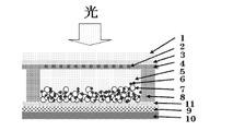
- FIG. 1 is a schematic view (cross-sectional view) showing an embodiment of the dye-sensitized solar cell of the present invention.
- FIG. 2 is a schematic view (cross-sectional view) showing one embodiment of a counter electrode of the dye-sensitized solar cell of the present invention.
- FIG. 3 is a schematic view (cross-sectional view) showing one embodiment of the dye-sensitized solar cell of the present invention.
- Example 1 Preparation of anodized titanium material
- Metal titanium plate titanium material, photoelectrode substrate
- trichlorethylene is degreased with trichlorethylene and then used in a nitriding furnace (NVF-600-PC, manufactured by Central Japan Reactor Industry)
- NVF-600-PC manufactured by Central Japan Reactor Industry
- a metal titanium plate was sandwiched between flat carbon materials installed in a nitriding furnace.
- the nitriding furnace was depressurized to 1 Pa or less, and 99.99% or more of high-purity nitrogen gas was introduced into the nitriding furnace to restore the pressure to 0.1 MPa (atmospheric pressure).
- the temperature of the nitriding furnace was raised to 950 ° C. over 2 hours.
- heat treatment was performed for 1 hour to form titanium nitride on the surface of the metal titanium plate.
- Metal titanium plate with titanium nitride formed on the surface 1.5 M sulfuric acid (manufactured by Wako Pure Chemical Industries, Ltd.), 0.05 M phosphoric acid (manufactured by Wako Pure Chemical Industries, Ltd.), 0.3 M hydrogen peroxide Anodizing was performed for 30 minutes at a current density of 4 A / dm 2 (Wako Pure Chemical Industries, Ltd.). A film of anatase-type titanium oxide was formed.
- the surface-treated titanium metal plate is washed with a solvent, then subjected to an oxygen flow (0.055MPa, 5 minutes) in a UV ozone cleaner UV253S (manufactured by Filgen Co., Ltd.), and then irradiated with ultraviolet rays for 30 minutes. Nitrogen flow (0.2 MPa, 7.5 min) was performed.
- Titanium oxide material (PST-18NR, manufactured by JGC Catalysts & Chemicals) is applied to the surface treatment material after this treatment by a squeegee method so that the application area is 16 cm 2 (40 mm ⁇ 40 mm). After baking for 15 minutes, this was coated 10 times to a film thickness of 30 ⁇ m (semiconductor layer, titanium oxide layer (porous)), and then fired at 450 ° C. for 1 hour.
- UV ozone cleaner UV ozone cleaner
- UV irradiation was performed for 30 minutes, and nitrogen flow (0.2 MPa, 7.5 min) was further performed.
- the fired metal titanium plate was immersed in the dye solution at 40 ° C. for 14 hours to form a titanium oxide layer (porous) containing a dye sensitizer. Thus, a photoelectrode material was obtained.
- the current collector was provided by polishing the surface-treated metal titanium using a precision grinder (Sunhayato Co., Ltd., AC-D12).
- Nickel-plated wiring with a line width of 500 ⁇ m and a thickness of 3 ⁇ m was provided by immersion for 1 minute and washing with water.
- a 50 mm ⁇ 50 mm material obtained by depositing 1 nm of platinum by electron beam evaporation on a substrate provided with nickel plating wiring was used as a counter electrode plate.
- a current collector was provided by coating (terminal) with Doutite D-550 (silver paste manufactured by Fujikura Kasei Co., Ltd.).
- a counter electrode plate was also prepared by depositing platinum (electrochemical reduction catalyst layer) on an FTO vapor deposition (coating) glass plate (transparent conductive glass) by 1 nm by electron beam vapor deposition.
- Evaluation results Table 1 shows the results of investigating the photoelectric conversion efficiency in the dye-sensitized solar cell of the substrate in which the counter electrode plate is provided with nickel plating as the collector electrode on the wiring.
- the pitch is 5 mm rather than 8 mm, the distance of the current flowing through the transparent electrode is shortened, and a high effect is obtained.
- Example 2 Preparation of anodized titanium material
- Metal titanium plate titanium material, photoelectrode substrate
- trichlorethylene is degreased with trichlorethylene and then used in a nitriding furnace (NVF-600-PC, manufactured by Central Japan Reactor Industry)
- NVF-600-PC manufactured by Central Japan Reactor Industry
- a metal titanium plate was sandwiched between flat carbon materials installed in a nitriding furnace.
- the nitriding furnace was depressurized to 1 Pa or less, and 99.99% or more of high-purity nitrogen gas was introduced into the nitriding furnace to restore the pressure to 0.1 MPa (atmospheric pressure).
- the temperature of the nitriding furnace was raised to 950 ° C. over 2 hours.
- heat treatment was performed for 1 hour to form titanium nitride on the surface of the metal titanium plate.
- Metal titanium plate with titanium nitride formed on the surface 1.5 M sulfuric acid (manufactured by Wako Pure Chemical Industries, Ltd.), 0.05 M phosphoric acid (manufactured by Wako Pure Chemical Industries, Ltd.), 0.3 M hydrogen peroxide Anodizing was performed for 30 minutes at a current density of 4 A / dm 2 (Wako Pure Chemical Industries, Ltd.). A film of anatase-type titanium oxide was formed.
- the surface-treated titanium metal plate is washed with a solvent, and then subjected to an oxygen flow (0.05 MPa, 5 minutes) in a UV ozone cleaner UV253S (manufactured by Filgen), followed by ultraviolet irradiation for 30 minutes. Nitrogen flow (0.2 MPa, 7.5 min) was performed.
- a titanium oxide material (PST-18NR, manufactured by JGC Catalysts & Chemicals) is applied to the surface treatment material after this treatment by a squeegee method so that the application area is 16 cm 2 (40 mm ⁇ 40 mm). After baking at 15 ° C. for 15 minutes, this was coated 10 times to a film thickness of 30 ⁇ m (semiconductor layer, titanium oxide layer (porous)), and then baked at 450 ° C. for 1 hour.
- UV irradiation was performed for 30 minutes, and nitrogen flow (0.2 MPa, 7.5 min) was further performed.
- the fired metal titanium plate was immersed in the dye solution at 40 ° C. for 14 hours to form a titanium oxide layer (porous) containing a dye sensitizer. Thus, a photoelectrode material was obtained.
- the current collector was provided by polishing the surface-treated metal titanium using a precision grinder (Sunhayato Co., Ltd., AC-D12).
- nickel titanium material KIOKALLOY-R manufactured by Daido Steel Co., Ltd.
- KIOKALLOY-R manufactured by Daido Steel Co., Ltd.
- a 50 mm ⁇ 50 mm material obtained by depositing 1 nm of platinum on a substrate provided with nickel titanium wiring by electron beam evaporation was used as a counter electrode plate.
- a current collector was provided by coating (terminal) with Doutite D-550 (silver paste manufactured by Fujikura Kasei Co., Ltd.).
- Doutite D-550 silver paste manufactured by Fujikura Kasei Co., Ltd.
- a counter electrode plate was also prepared by depositing platinum on an FTO-deposited glass plate by 1 nm by electron beam evaporation.
- Evaluation results Table 2 shows the results of examining the photoelectric conversion efficiency in the dye-sensitized solar cell of the substrate having the nickel-titanium wiring provided on the counter electrode plate.
- Example 3 Preparation of anodized titanium material
- Metal titanium plate titanium material, photoelectrode substrate
- trichlorethylene is degreased with trichlorethylene and then used in a nitriding furnace (NVF-600-PC, manufactured by Central Japan Reactor Industry)
- NVF-600-PC manufactured by Central Japan Reactor Industry
- a metal titanium plate was sandwiched between flat carbon materials installed in a nitriding furnace.
- the nitriding furnace was depressurized to 1 Pa or less, and 99.99% or more of high-purity nitrogen gas was introduced into the nitriding furnace to restore the pressure to 0.1 MPa (atmospheric pressure).
- the temperature of the nitriding furnace was raised to 950 ° C. over 2 hours.
- heat treatment was performed for 1 hour to form titanium nitride on the surface of the metal titanium plate.
- Metal titanium plate with titanium nitride formed on the surface 1.5 M sulfuric acid (manufactured by Wako Pure Chemical Industries, Ltd.), 0.05 M phosphoric acid (manufactured by Wako Pure Chemical Industries, Ltd.), 0.3 M hydrogen peroxide Anodizing was performed for 30 minutes at a current density of 4 A / dm 2 (Wako Pure Chemical Industries, Ltd.). A film of anatase-type titanium oxide was formed.
- the surface-treated titanium metal plate is washed with a solvent, and then subjected to an oxygen flow (0.05 MPa, 5 minutes) in a UV ozone cleaner UV253S (manufactured by Filgen), followed by ultraviolet irradiation for 30 minutes. Nitrogen flow (0.2 MPa, 7.5 min) was performed.
- Titanium oxide material (PST-18NR, manufactured by JGC Catalysts & Chemicals) is applied to the surface treatment material after this treatment by a squeegee method so that the application area is 16 cm 2 (40 mm ⁇ 40 mm). After baking for 15 minutes, this was coated 10 times to a film thickness of 30 ⁇ m (semiconductor layer, titanium oxide layer (porous)), and then fired at 450 ° C. for 1 hour.
- UV irradiation was performed for 30 minutes, and nitrogen flow (0.2 MPa, 7.5 min) was further performed.
- the fired metal titanium plate was immersed in the dye solution at 40 ° C. for 14 hours to form a titanium oxide layer (porous) containing a dye sensitizer. Thus, a photoelectrode material was obtained.
- the current collector was provided by polishing the surface-treated metal titanium using a precision grinder (Sunhayato Co., Ltd., AC-D12).
- Ti Current collector
- a 50 mm x 50 mm material obtained by depositing 1 nm of platinum by electron beam evaporation on a substrate provided with titanium wiring was used as a counter electrode plate.
- a current collector was provided by coating (terminal) with Doutite D-550 (silver paste manufactured by Fujikura Kasei Co., Ltd.).
- Doutite D-550 silver paste manufactured by Fujikura Kasei Co., Ltd.
- a counter electrode plate was also prepared by depositing platinum on an FTO-deposited glass plate by electron beam deposition to a thickness of 1 nm.
- Evaluation results Table 3 shows the results of examining the photoelectric conversion efficiency in the dye-sensitized solar cell of the substrate in which the counter electrode plate is provided with the titanium wiring.
- Example 4 Preparation of anodized titanium material
- Metal titanium plate titanium material, photoelectrode substrate
- trichlorethylene is degreased with trichlorethylene and then used in a nitriding furnace (NVF-600-PC, manufactured by Central Japan Reactor Industry)
- NVF-600-PC manufactured by Central Japan Reactor Industry
- a metal titanium plate was sandwiched between flat carbon materials installed in a nitriding furnace.
- the nitriding furnace was depressurized to 1 Pa or less, and 99.99% or more of high-purity nitrogen gas was introduced into the nitriding furnace to restore the pressure to 0.1 MPa (atmospheric pressure).
- the temperature of the nitriding furnace was raised to 950 ° C. over 2 hours.
- heat treatment was performed for 1 hour to form titanium nitride on the surface of the metal titanium plate.
- a titanium metal plate with titanium nitride formed on the surface is made of 1.5 M sulfuric acid (manufactured by Wako Pure Chemical Industries, Ltd.), 0.05 M phosphoric acid (manufactured by Wako Pure Chemical Industries, Ltd.), 0.3 M hydrogen peroxide (Japanese Anodizing was performed for 30 minutes at a current density of 4 A / dm 2 at Kogure Pharmaceutical Co., Ltd. A film of anatase-type titanium oxide was formed.
- Block layer (lower layer: aluminum oxide, upper layer: titanium oxide)
- this material was immersed in an aqueous solution of 50 mM aluminum chloride (manufactured by Wako Pure Chemical Industries, Ltd.) for 2 minutes at room temperature and then dried at 450 ° C. Atmospheric oxidation for 15 minutes.
- Titanium oxide material (PST-18NR, manufactured by JGC Catalysts & Chemicals) is applied to the surface treatment material after this treatment by a squeegee method so that the application area is 16 cm 2 (40 mm ⁇ 40 mm). (Semiconductor layer, titanium oxide layer (porous)).
- the fired metal titanium plate was immersed in the dye solution at 40 ° C. for 14 hours to form a titanium oxide layer (porous) containing a dye sensitizer. Thus, a photoelectrode material was obtained.
- the current collector was provided by polishing the surface-treated metal titanium using a precision grinder (Sunhayato Co., Ltd., AC-D12).
- Ti Current collector
- platinum electrochemical reduction catalyst layer
- 50mm x 50mm material Used as a plate.
- a special solder cerazour luza # 186 manufactured by Kuroda Techno was used to provide a terminal.
- a counter electrode plate was also prepared by depositing platinum on an FTO-deposited glass plate by electron beam deposition to a thickness of 1 nm.
- Evaluation results Table 4 shows the results of examining the photoelectric conversion efficiency in the dye-sensitized solar cell of the substrate in which titanium wiring is provided on the counter electrode plate.
- Example 5 Preparation of anodized titanium material
- Metal titanium plate titanium material, photoelectrode substrate
- trichlorethylene is degreased with trichlorethylene and then used in a nitriding furnace (NVF-600-PC, manufactured by Central Japan Reactor Industry)
- NVF-600-PC manufactured by Central Japan Reactor Industry
- a metal titanium plate was sandwiched between flat carbon materials installed in a nitriding furnace.
- the nitriding furnace was depressurized to 1 Pa or less, and 99.99% or more of high-purity nitrogen gas was introduced into the nitriding furnace to restore the pressure to 0.1 MPa (atmospheric pressure).
- the temperature of the nitriding furnace was raised to 950 ° C. over 2 hours.
- heat treatment was performed for 1 hour to form titanium nitride on the surface of the metal titanium plate.
- a titanium metal plate with titanium nitride formed on the surface is made of 1.5 M sulfuric acid (manufactured by Wako Pure Chemical Industries, Ltd.), 0.05 M phosphoric acid (manufactured by Wako Pure Chemical Industries, Ltd.), 0.3 M hydrogen peroxide (Japanese Anodizing was performed for 30 minutes at a current density of 4 A / dm 2 at Kogure Pharmaceutical Co., Ltd. A film of anatase-type titanium oxide was formed.
- the surface-treated titanium metal plate is washed with a solvent, and then subjected to an oxygen flow (0.05 MPa, 5 minutes) in a UV ozone cleaner UV253S (manufactured by Filgen), followed by ultraviolet irradiation for 30 minutes. Nitrogen flow (0.2 MPa, 7.5 min) was performed. *
- Block layer (lower layer: aluminum oxide, upper layer: titanium oxide) This material was immersed in an aqueous solution of 150 mM aluminum chloride (manufactured by Wako Pure Chemical Industries, Ltd.) at room temperature for 2 minutes and dried, and then oxidized at 450 ° C. for 15 minutes. This process was repeated twice. Next, it was immersed in an aqueous solution of 120 mM titanium tetrachloride (manufactured by Wako Pure Chemical Industries, Ltd.) for 30 minutes at 70 ° C. and then dried at 450 ° C. for 15 minutes. This process was repeated twice.
- Titanium oxide material (PST-18NR, manufactured by JGC Catalysts & Chemicals) is applied to the surface treatment material after this treatment by a squeegee method so that the application area is 16 cm 2 (40 mm ⁇ 40 mm). This was baked for 15 minutes, and this was coated five times to a film thickness of 15 ⁇ m (semiconductor layer), and then baked at 450 ° C. for 1 hour. Furthermore, after performing an oxygen flow (0.05 MPa, 5 minutes) in a UV ozone cleaner UV253S (manufactured by Philgen), ultraviolet irradiation was performed for 30 minutes, and a nitrogen flow (0.2 MPa, 7.5 min) was further performed.
- an oxygen flow 0.05 MPa, 5 minutes
- UV253S manufactured by Philgen
- the current collector was provided by polishing the surface-treated metal titanium using a precision grinder (Sunhayato Co., Ltd., AC-D12).
- a precision grinder (Sunhayato Co., Ltd., AC-D12).
- (3) Production of counter electrode plate As a counter electrode, a glass substrate (thickness 1 mm ⁇ 100 mm ⁇ 100 mm) was washed with acetone by ultrasonic degreasing for 15 minutes. Next, a titanium sputtering process was performed to coat a titanium film having a thickness of 200 nm. Next, titanium ion plating was performed to form a titanium layer having a thickness of 20 ⁇ m.
- Titanium wiring was provided.
- a material of 50 mm ⁇ 50 mm with platinum deposited by 1 nm by electron beam evaporation was used as a counter electrode plate.
- a special solder cerazour luza # 186 (manufactured by Kuroda Techno) was used to provide a terminal.
- a counter electrode plate was also prepared by depositing platinum on an FTO-deposited glass plate by electron beam deposition to a thickness of 1 nm.
- Evaluation results Table 5 shows the results of examining the photoelectric conversion efficiency in the dye-sensitized solar cell of the substrate in which the counter electrode plate was provided with titanium wiring.
Landscapes
- Engineering & Computer Science (AREA)
- Power Engineering (AREA)
- Microelectronics & Electronic Packaging (AREA)
- Chemical & Material Sciences (AREA)
- Chemical Kinetics & Catalysis (AREA)
- Electrochemistry (AREA)
- Hybrid Cells (AREA)
- Photovoltaic Devices (AREA)
- Manufacturing & Machinery (AREA)
Abstract
Description
光電極と対極とが電解質層を介して対向配置された色素増感型太陽電池であって、
(1)光電極が、チタン材料上に、色素増感剤を含有する酸化チタン層が形成されたものであり、
(2)対極が、透明導電性ガラス又は透明導電性フィルム上に、電気化学的還元触媒層がコーティングされたものであり、該対極に集電極が設けられていることを特徴とする、色素増感太陽電池。
前記対極が、透明導電性ガラス又は透明導電性フィルム上に、集電極を設けた後に電気化学的還元触媒層がコーティングされたものであることを特徴とする、前記項1記載の色素増感太陽電池。
前記チタン材料が、金属チタン、チタン合金、表面処理した金属チタン及び表面処理したチタン合金からなる群から選ばれる材料であることを特徴とする、前記項1又は2に記載の色素増感太陽電池。
前記対極に設ける集電極が、耐食性の高い材料群から選ばれる材料であることを特徴とする、前記項1~3のいずれかに記載の色素増感太陽電池。
前記対極に設ける集電極が、金、銀、銅、白金、ロジウム、パラジウム、イリジウム、アルミニウム、ニッケル、チタン、ニオブ、タンタル、ジルコニウム、タングステン、ニッケル、クロム及びモリブデンからなる群から選ばれる金属;前記金属を主成分とする合金;並びに、カーボン、グラファイト、カーボンナノチューブ及びフラーレンからなる群から選ばれる炭素材;ポリチォフェンからなる群から選ばれる導電性高分子材料;から選ばれる少なくとも1種類の材料であることを特徴とする、前記項1~4のいずれかに記載の色素増感太陽電池。
前記対極に設ける集電極に設ける耐食性の高い材料が、金属チタン及びチタン合金からなる群から選ばれる材料であることを特徴とする、前記項1~5のいずれかに記載の色素増感太陽電池。
前記集電極における開口面積部が、対極の全体面積の50~99%であることを特徴とする、前記項1~6のいずれかに記載の色素増感太陽電池。
前記集電極の厚みが、0.01~100μmであることを特徴とする、前記項1~7のいずれかに記載の色素増感太陽電池。
前記酸化チタン層の形状が、長方形であることを特徴とする、前記項1~8のいずれかに記載の色素増感太陽電池。
前記電気化学的還元触媒層が、白金触媒層であることを特徴とする、前記項1~9のいずれかに記載の色素増感太陽電池。
前記対極の透明導電性ガラス又は透明導電性フィルムが、反射防止膜加工したものであることを特徴とする、前記項1~10のいずれかに記載の色素増感太陽電池。
前記対極が、透明導電性ガラス又は透明導電性フィルムの光照射面に更に反射防止フィルムを設けているものであることを特徴とする、前記項1~11のいずれかに記載の色素増感太陽電池。
集光装置が対極側に配置されていることを特徴とする、前記項1~12のいずれかに記載の色素増感太陽電池。
前記光電極が、チタン材料上にブロック層が設けられ、更に該ブロック層上に色素増感剤を含有する酸化チタン層が形成されたものであることを特徴とする、前記項1~12のいずれかに記載の色素増感太陽電池。
前記ブロック層が、酸化チタンの層、酸化アルミニウムの層、酸化ケイ素の層、酸化ジルコニウムの層、チタン酸ストロンチウムの層、酸化マグネシウムの層及び酸化ニオブの層からなる群から選ばれる少なくとも1種類の材料の層であることを特徴とする、前記項14に記載の色素増感太陽電池。
前記ブロック層が、酸化チタンの層、酸化アルミニウムの層、酸化ケイ素の層、酸化ジルコニウムの層、チタン酸ストロンチウムの層、酸化マグネシウムの層及び酸化ニオブの層からなる群から選ばれる少なくともの2つの層で構成されること特徴とする、前記項14に記載の色素増感太陽電池。
前記ブロック層が、酸化チタンの層、酸化アルミニウムの層及び酸化ニオブの層からなる群から選ばれる少なくともの2つの層で構成されること特徴とする、前記項14に記載の色素増感太陽電池。
前記項1~17のいずれかに記載の色素増感型太陽電池であって、
前記光電極のチタン材料が、以下の表面処理方法により製造されるものであることを特徴とする、色素増感太陽電池:
(1)金属チタン材料又はチタン合金材料の表面にチタン窒化物を形成する工程、及び
(2)工程(1)で得られた、表面にチタン窒化物が形成された金属チタン材料又はチタン合金材料を、チタンに対してエッチング作用を有する電解液を用いて、火花放電発生電圧以上にて陽極酸化を行い、アナターゼ型酸化チタンの皮膜を形成する工程。
前記項1~17のいずれかに記載の色素増感型太陽電池であって、
前記光電極のチタン材料が、以下の表面処理方法により製造されるものであることを特徴とする、色素増感太陽電池:
(1)金属チタン材料又はチタン合金材料の表面にチタン窒化物を形成する工程、
(2)工程(1)で得られた、表面にチタン窒化物が形成された金属チタン材料又はチタン合金材料を、チタンに対してエッチング作用を有しない電解液中で、陽極酸化を行う工程、及び
(3)工程(2)で得られた、陽極酸化処理を施した金属チタン材料又はチタン合金材料を、酸化性雰囲気中で加熱処理を行い、アナターゼ型酸化チタンの皮膜を形成する工程。
前記チタン窒化物を形成する工程が、PVD処理、CVD処理、溶射処理、アンモニアガス雰囲気下での加熱処理及び窒素ガス雰囲気下での加熱処理よりなる群から選択された1種の処理方法により行うものであることを特徴とする、前記項18又は19に記載の色素増感太陽電池。
前記窒素ガス雰囲気下での加熱処理が、酸素トラップ剤の存在下で実施するものであることを特徴とする、前記項20に記載の色素増感太陽電池。
光電極と対極とが電解質層を介して対向配置された色素増感型太陽電池の製造方法であって、
色素増感型太陽電池が、
(1)光電極が、チタン材料上に、色素増感剤を含有する酸化チタン層が形成されたものであり、
(2)対極が、透明導電性ガラス又は透明導電性フィルム上に、電気化学的還元触媒層がコーティングされたものであり、該対極に集電極が設けられてあり、
光電極のチタン材料が、以下の表面処理方法により製造されることを特徴とする、製造方法:
(1)金属チタン材料又はチタン合金材料の表面にチタン窒化物を形成する工程、及び
(2)工程(1)で得られた、表面にチタン窒化物が形成された金属チタン材料又はチタン合金材料を、チタンに対してエッチング作用を有する電解液を用いて、火花放電発生電圧以上にて陽極酸化を行い、アナターゼ型酸化チタンの皮膜を形成する工程。
光電極と対極とが電解質層を介して対向配置された色素増感型太陽電池の製造方法であって、
色素増感型太陽電池が、
(1)光電極が、チタン材料上に、色素増感剤を含有する酸化チタン層が形成されたものであり、
(2)対極が、透明導電性ガラス又は透明導電性フィルム上に、電気化学的還元触媒層がコーティングされたものであり、該対極に集電極が設けられてあり、
光電極のチタン材料が、以下の表面処理方法により製造されることを特徴とする、製造方法:
(1)金属チタン材料又はチタン合金材料の表面にチタン窒化物を形成する工程、
(2)工程(1)で得られた、表面にチタン窒化物が形成された金属チタン材料又はチタン合金材料を、チタンに対してエッチング作用を有しない電解液中で、陽極酸化を行う工程、及び
(3)工程(2)で得られた、陽極酸化処理を施した金属チタン材料又はチタン合金材料を、酸化性雰囲気中で加熱処理を行い、アナターゼ型酸化チタンの皮膜を形成する工程。
(1)金属チタン材料又はチタン合金材料の表面にチタン窒化物を形成する工程、及び
(2)工程(1)で得られた、表面にチタン窒化物が形成された金属チタン材料又はチタン合金材料を、チタンに対してエッチング作用を有する電解液を用いて、火花放電発生電圧以上にて陽極酸化を行い、アナターゼ型酸化チタンの皮膜を形成する工程
を含む方法により製造されることが好ましい。
(1)金属チタン材料又はチタン合金材料の表面にチタン窒化物を形成する工程、
(2)工程(1)で得られた、表面にチタン窒化物が形成された金属チタン材料又はチタン合金材料を、チタンに対してエッチング作用を有しない電解液中で、陽極酸化を行う工程、及び
(3)工程(2)で得られた、陽極酸化処理を施した金属チタン材料又はチタン合金材料を、酸化性雰囲気中で加熱処理を行い、アナターゼ型酸化チタンの皮膜を形成する工程、
を含む方法により製造されることが好ましい。
(1)光電極が、チタン材料上に、色素増感剤を含有する酸化チタン層が形成されたものであり、
(2)対極が、ITO又はFTOでコーティングされた透明導電性ガラス又は透明導電性フィルム上に、0.5~1 nmの厚みを有する白金触媒層があり、該対極に集電極が設けられており、
(3)前記電解質層が、酸化還元種を含む非水系電解液であり、該酸化還元種がヨウ化リチウム、ヨウ化ナトリウム、ヨウ化カリウム及びヨウ化カルシウムから選ばれる1種単独又は2種類以上のヨウ化物塩とヨウ素との組み合わせを含むものであり、
(4)前記集電極が、ストライプ状又は格子状に配線されており、該集電極の開口面積部が対極の全体面積の80~99%であり、該集電極の材料がチタン合金のTi-Niであり、該集電極の厚みが1μm~100μmである、
ことが好ましい。
光電極と対極とが電解質層を介して対向配置された色素増感型太陽電池であって、
(1)光電極が、チタン材料上に、色素増感剤を含有する酸化チタン層が形成されたものであり、
(2)対極が、透明導電性ガラスまたは透明導電性フィルム上に、電気化学的還元触媒層がコーティングされたものであり、該対極に集電極が設けられていることを特徴とする。
色素増感型太陽電池は、光電極と対極とが電解質層を介して対向配置されている。光電極は、金属チタン、チタン合金、表面処理した金属チタン及び表面処理したチタン合金からなる群から選ばれる材料(以下「チタン材料」とも記す、光電極基板)上に、色素増感剤を含有する酸化チタン層が形成されたものである。
光電極基板は、チタン材料自体を用いることも可能である。チタン材料は基材となる。
光電極基板(光電極のチタン材料)は、以下の表面処理方法により製造される、表面にアナターゼ型酸化チタンを有する半導体層を有する光電極基板からなるものであることが好ましい。
(2)工程(1)で得られた、表面にチタン窒化物が形成された金属チタン材料又はチタン合金材料を、チタンに対してエッチング作用を有する電解液を用いて、火花放電発生電圧以上にて陽極酸化を行い、アナターゼ型酸化チタンの皮膜を形成する工程。
光電極基板(光電極のチタン材料)は、以下の表面処理方法により製造される、表面にアナターゼ型酸化チタンを有する半導体層を有する光電極基板からなるものであることが好ましい。
(2)工程(1)で得られた、表面にチタン窒化物が形成された金属チタン材料又はチタン合金材料を、チタンに対してエッチング作用を有しない電解液中で、陽極酸化を行う工程、及び
(3)工程(2)で得られた、陽極酸化処理を施した金属チタン材料又はチタン合金材料を、酸化性雰囲気中で加熱処理を行い、アナターゼ型酸化チタンの皮膜を形成する工程。
チタン材料(金属チタン又はチタン合金)の表面にチタン窒化物を形成する工程(工程(1))では、チタン材料の表面にチタン窒化物の層を、通常0.1~100μm程度形成することができる。
表面処理方法Aでは、表面にチタン窒化物が形成されたチタン材料を、チタンに対してエッチング作用を有する電解液を用いて、火花放電発生電圧以上にて陽極酸化を行い、アナターゼ型酸化チタンの皮膜を形成する(工程(2))。
表面処理方法Bでは、表面にチタン窒化物が形成されたチタン材料を、チタンに対してエッチング作用を有しない電解液中で、陽極酸化を行い(工程(2))、次いで陽極酸化処理を施したチタン材料を、酸化性雰囲気中で加熱処理を行い、アナターゼ型酸化チタンの皮膜を形成する(工程(3))。表面にアナターゼ型酸化チタンを有する半導体層を有する高い光電変換効率を好適に発揮する光電極基板を製造できる。
次に、表面にチタンの酸化皮膜が形成されたチタン材料を、酸化性雰囲気中で加熱処理を行い、アナターゼ型酸化チタンの皮膜を形成する(工程(3))。
本発明の色素増感型太陽電池では、光電極基板がチタン材料で形成され、更にブロック層を設けることで、変換効率を著しく高く向上させることが可能である。
光電極は、チタン材料(金属チタン、チタン合金、表面処理した金属チタン及び表面処理したチタン合金からなる群から選ばれる材料)上に色素増感剤を含有する酸化チタン層(半導体層)を形成されたものである。
光電極は、チタン材料上に色素増感剤を含有する酸化チタン層が形成されたものである。
対極には集電極が設けられている。
本発明品においては、透明導電膜表面に集電効果を有する材料をストライプ状、格子状等に配線することで、大面積の色素増感太陽電池においても変換効率を低下させることがない。この集電効果を有する材料が集電極である。ストライプ状、格子状等に配線された集電極は、そのターミナルを通じて電流を取り出す。前記ターミナルは、銀、はんだ等のペースト剤をコーティングしたものが好ましい。
集電極の線抵抗を4.5Ω/cm、開口率を90%とした場合、
ピッチ8mmの際、線幅0.8mm、ニッケルの膜厚は1.88μmとなり、
ピッチ5mmの際、線幅0.5mm、ニッケルの膜厚は3μmとなり、
ピッチ2mmの際、線幅0.2mm、ニッケルの膜厚は7.5μmとなり、
ピッチ1mmの際、線幅0.1mm、ニッケルの膜厚は15μmとなる。
電解質層は、光励起され、半導体層へ電子注入を果たした色素増感剤に、電子を供給でき、色素増感剤を還元できる層であれば良い。電解質層は、更に、電子を失った電解質に、対極の白金触媒層から電子を供給される層であればよい。
色素増感型太陽電池では、光電極と対極との接触を防ぐためにセパレータ(スペーサー)を設置することが好ましい。
本色素増感型太陽電池では、集光装置が対極側に配置されているものを用いれば、さらに高い光変換効率に相当する高い発電が可能である。
本発明の色素増感型太陽電池は、公知の方法に従って製造できる。
(1)陽極酸化処理したチタン材料の作製
金属チタン板(チタン材料、光電極基板)を、トリクロロエチレンを用いて脱脂処理した後、窒化炉(NVF-600-PC、中日本炉工業製)を使用して、脱脂処理した金属チタン板の表面にチタン窒化物を形成した。
上記表面処理した50 mm×50 mmの金属チタン板を光電極として用いて、色素増感型太陽電池を作製した。
対極としては、FTO(Fluorine Tin Oxide)蒸着(コーティング)ガラス板(旭硝子(株)製)(透明導電性ガラス)に低圧水銀ランプに10分間照射しUVオゾン洗浄を行った。
次に、無電解ニッケルめっき液ICPニコロンGME(NP)(奥野製薬工業(株)製)に80℃で4分間浸漬し、蒸留水で10秒間流水洗浄した後、同めっき液に60℃で60分間浸漬と水洗することで、線幅500μm、厚さ3μmのニッケルめっき配線を設けた。
光電極と対極との隙間に30μmのアイオノマー樹脂のスペーサ―(ハイミラン、三井・デュポン ポリケミカル(株)製)を設置した。
対極板に集電極としてニッケルめっきを配線に設けた基板の色素増感太陽電池において、光電変換効率について調べた結果を、表1に示した。

(1)陽極酸化処理したチタン材料の作製
金属チタン板(チタン材料、光電極基板)を、トリクロロエチレンを用いて脱脂処理した後、窒化炉(NVF-600-PC、中日本炉工業製)を使用して、脱脂処理した金属チタン板の表面にチタン窒化物を形成した。
上記表面処理した50 mm×50 mmの金属チタン板を光電極として用いて、色素増感型太陽電池を作製した。
対極としては、FTO(Fluorine Tin Oxide)蒸着(コーティング)ガラス板(旭硝子(株)製)(透明導電性ガラス)に線幅500μm×48 mmの開口をフォトエッチング処理により設けた厚さ0.2 mmのステンレス製(SUS304)板をポリイミドテープ(CHYUNYIHTAPE Co.,Ltd製、PB416-10-30)で貼り付けた。
次に、電子ビーム蒸着によりニッケルチタン材KIOKALLOY-R(大同特殊鋼(株)製)を1μm蒸着することで、線幅500μm、厚さ1μmのニッケルチタン配線を設けた。
光電極と対極との隙間に30μmのアイオノマー樹脂のスペーサ―(ハイミラン、三井・デュポン ポリケミカル(株)製)を設置した。
対極板にニッケルチタン配線を設けた基板の色素増感太陽電池において、光電変換効率について調べた結果を、表2に示した。

(1)陽極酸化処理したチタン材料の作製
金属チタン板(チタン材料、光電極基板)を、トリクロロエチレンを用いて脱脂処理した後、窒化炉(NVF-600-PC、中日本炉工業製)を使用して、脱脂処理した金属チタン板の表面にチタン窒化物を形成した。
上記表面処理した50 mm×50 mmの金属チタン板を光電極として用いて、色素増感型太陽電池を作製した。
対極としては、FTO(Fluorine Tin Oxide)蒸着(コーティング)ガラス板(旭硝子(株)製)(透明導電性ガラス)に線幅500μm×48 mmの開口をフォトエッチング処理により設けた厚さ0.2 mmのステンレス製(SUS304)板をポリイミドテープ(CHYUNYIHTAPE Co.,Ltd製、PB416C-10-30)で貼り付けた。
次に、電子ビーム蒸着によりチタン材を1μm蒸着することで、線幅500μm、厚さ1μmの集電極としてチタンを配線を設けた。
光電極と対極との隙間に30μmのアイオノマー樹脂のスペーサ―(ハイミラン、三井・デュポン ポリケミカル(株)製)を設置した。
対極板にチタン配線を設けた基板の色素増感太陽電池において、光電変換効率について調べた結果を、表3に示した。
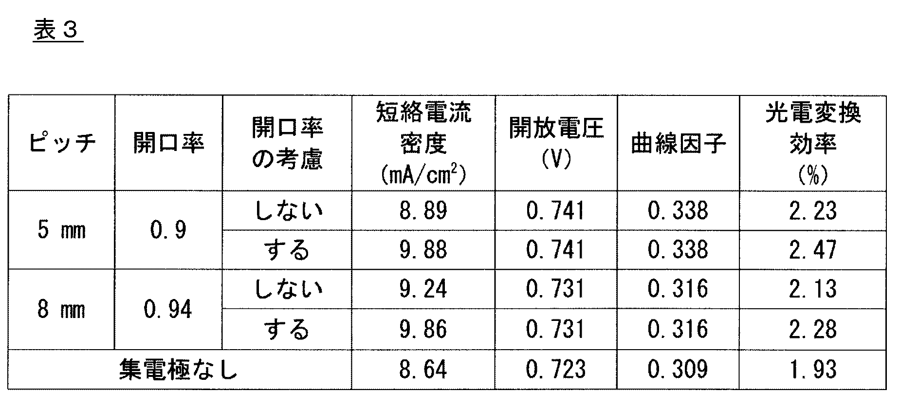
(1)陽極酸化処理したチタン材料の作製
金属チタン板(チタン材料、光電極基板)を、トリクロロエチレンを用いて脱脂処理した後、窒化炉(NVF-600-PC、中日本炉工業製)を使用して、脱脂処理した金属チタン板の表面にチタン窒化物を形成した。
上記表面処理した50 mm×50 mmの金属チタン板を光電極として用いて、色素増感型太陽電池を作製した。
先ず、上記表面処理した金属チタン板を溶剤にて洗浄後、本材料を50mM 塩化アルミニウム(和光純薬工業(株)製)水溶液に常温にて2分間浸漬、乾燥させた後、450℃にて15分間大気酸化させた。
対極としては、ガラス基板(厚さ1mmx100mmx100mm)をアセトンにて超音波脱脂による洗浄を15分間実施した。次に、チタンのスパッタリング処理を実施し、厚さ200nmのチタン膜をコーティングした。次に、チタンのイオンプレーティングを実施し、厚さ20μmのチタン層を形成させた。
次に、高精度フォトリゾグラフ処理にて、チタン集電部のパターニングを実施し、5mmピッチにて線幅0.5mmのチタンの配線を設けた。
光電極と対極との隙間に30μmのアイオノマー樹脂のスペーサ―(ハイミラン、三井・デュポン ポリケミカル(株)製)を設置した。
対極板にチタン配線を設けた基板の色素増感太陽電池において、光電変換効率について調べた結果を、表4に示した。
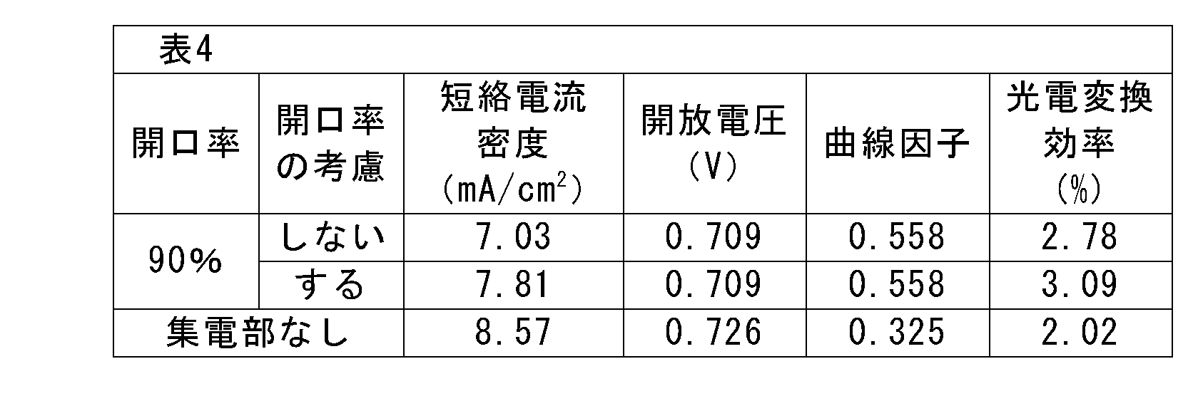
(1)陽極酸化処理したチタン材料の作製
金属チタン板(チタン材料、光電極基板)を、トリクロロエチレンを用いて脱脂処理した後、窒化炉(NVF-600-PC、中日本炉工業製)を使用して、脱脂処理した金属チタン板の表面にチタン窒化物を形成した。
上記表面処理した50 mm×50 mmの金属チタン板を光電極として用いて、色素増感型太陽電池を作製した。
本材料を150mM 塩化アルミニウム(和光純薬工業(株)製)水溶液に常温にて2分間浸漬、乾燥させた後、450℃にて15分間大気酸化させた。この処理を2回繰り返した。次に120mM 四塩化チタン(和光純薬工業(株)製)水溶液に、70℃にて30分間浸漬、乾燥させた後、450℃で15分間させた。この処理を2回繰り返した。塩化アルミニウム水溶液での処理、四塩化チタン水溶液での処理を実施することにより、下層(チタン材料側)に緻密な酸化アルミニウム層、上層(電解質層又は多孔質酸化チタン側)に緻密な酸化チタン層が形成されたブロック層(2層構造)を形成させた。
(3)対極板の作製
対極としては、ガラス基板(厚さ1mmx100mmx100mm)をアセトンにて超音波脱脂による洗浄を15分間実施した。次に、チタンのスパッタリング処理を実施し、厚さ200nmのチタン膜をコーティングした。次に、チタンのイオンプレーティングを実施し、厚さ20μmのチタン層を形成させた。
次に、高精度フォトリゾグラフ処理にて、チタン集電部のパターニングを実施し、0.5mmピッチにて線幅0.05mm、1mmピッチにて線幅0.1mm、2mmピッチにて線幅0.2mmのチタンの配線を設けた。
光電極と対極との隙間に30μmのアイオノマー樹脂のスペーサ―(ハイミラン、三井・デュポン ポリケミカル(株)製)を設置した。
対極板にチタン配線を設けた基板の色素増感太陽電池において、光電変換効率について調べた結果を、表5に示した。
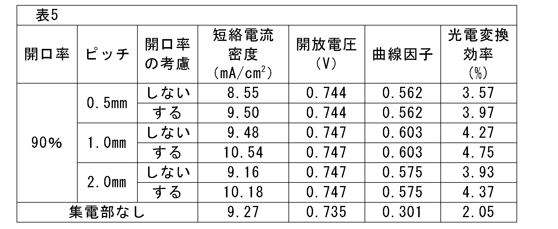
2 集電極
3 導電膜
1+3 透明導電性ガラス又は透明導電性フィルム
4 電気化学的還元触媒層
5 電解質層
6 色素増感剤
7 酸化チタン層
8 セパレータ、封止材
9 陽極酸化層
10 金属チタン層(光電極)
11 ブロック層
Claims (21)
- 光電極と対極とが電解質層を介して対向配置された色素増感型太陽電池であって、
(1)光電極が、チタン材料上に、色素増感剤を含有する酸化チタン層が形成されたものであり、
(2)対極が、透明導電性ガラス又は透明導電性フィルム上に、電気化学的還元触媒層がコーティングされたものであり、該対極に集電極が設けられていることを特徴とする、色素増感太陽電池。 - 前記対極が、透明導電性ガラス又は透明導電性フィルム上に、集電極を設けた後に電気化学的還元触媒層がコーティングされたものであることを特徴とする、請求項1記載の色素増感太陽電池。
- 前記チタン材料が、金属チタン、チタン合金、表面処理した金属チタン及び表面処理したチタン合金からなる群から選ばれる材料であることを特徴とする、請求項1又は2に記載の色素増感太陽電池。
- 前記対極に設ける集電極が、耐食性の高い材料群から選ばれる材料であることを特徴とする、請求項1~3のいずれかに記載の色素増感太陽電池。
- 前記対極に設ける集電極が、金、銀、銅、白金、ロジウム、パラジウム、イリジウム、アルミニウム、ニッケル、チタン、ニオブ、タンタル、ジルコニウム、タングステン、ニッケル、クロム及びモリブデンからなる群から選ばれる金属;前記金属を主成分とする合金;並びに、カーボン、グラファイト、カーボンナノチューブ及びフラーレンからなる群から選ばれる炭素材;ポリチォフェンからなる群から選ばれる導電性高分子材料;から選ばれる少なくとも1種類の材料であることを特徴とする、請求項1~4のいずれかに記載の色素増感太陽電池。
- 前記対極に設ける集電極に設ける耐食性の高い材料が、金属チタン及びチタン合金からなる群から選ばれる材料であることを特徴とする、請求項1~5のいずれかに記載の色素増感太陽電池。
- 前記集電極における開口面積部が、対極の全体面積の50~99%であることを特徴とする、請求項1~6のいずれかに記載の色素増感太陽電池。
- 前記集電極の厚みが、0.01~100μmであることを特徴とする、請求項1~7のいずれかに記載の色素増感太陽電池。
- 前記酸化チタン層の形状が、長方形であることを特徴とする、請求項1~8のいずれかに記載の色素増感太陽電池。
- 前記電気化学的還元触媒層が、白金触媒層であることを特徴とする、請求項1~9のいずれかに記載の色素増感太陽電池。
- 前記対極の透明導電性ガラス又は透明導電性フィルムが、反射防止膜加工したものであることを特徴とする、請求項1~10のいずれかに記載の色素増感太陽電池。
- 前記対極が、透明導電性ガラス又は透明導電性フィルムの光照射面に更に反射防止フィルムを設けているものであることを特徴とする、請求項1~11のいずれかに記載の色素増感太陽電池。
- 集光装置が対極側に配置されていることを特徴とする、請求項1~12のいずれかに記載の色素増感太陽電池。
- 前記光電極が、チタン材料上にブロック層が設けられ、更に該ブロック層上に色素増感剤を含有する酸化チタン層が形成されたものであることを特徴とする、請求項1~12のいずれかに記載の色素増感太陽電池。
- 前記ブロック層が、酸化チタンの層、酸化アルミニウムの層、酸化ケイ素の層、酸化ジルコニウムの層、チタン酸ストロンチウムの層、酸化マグネシウムの層及び酸化ニオブの層からなる群から選ばれる少なくとも1種類の材料の層であることを特徴とする、請求項14に記載の色素増感太陽電池。
- 前記ブロック層が、酸化チタンの層、酸化アルミニウムの層、酸化ケイ素の層、酸化ジルコニウムの層、チタン酸ストロンチウムの層、酸化マグネシウムの層及び酸化ニオブの層からなる群から選ばれる少なくともの2つの層で構成されること特徴とする、請求項14に記載の色素増感太陽電池。
- 前記ブロック層が、酸化チタンの層、酸化アルミニウムの層及び酸化ニオブの層からなる群から選ばれる少なくともの2つの層で構成されること特徴とする、請求項14に記載の色素増感太陽電池。
- 請求項1~17のいずれかに記載の色素増感型太陽電池であって、
前記光電極のチタン材料が、以下の表面処理方法により製造されるものであることを特徴とする、色素増感太陽電池:
(1)金属チタン材料又はチタン合金材料の表面にチタン窒化物を形成する工程、及び
(2)工程(1)で得られた、表面にチタン窒化物が形成された金属チタン材料又はチタン合金材料を、チタンに対してエッチング作用を有する電解液を用いて、火花放電発生電圧以上にて陽極酸化を行い、アナターゼ型酸化チタンの皮膜を形成する工程。 - 請求項1~17のいずれかに記載の色素増感型太陽電池であって、
前記光電極のチタン材料が、以下の表面処理方法により製造されるものであることを特徴とする、色素増感太陽電池:
(1)金属チタン材料又はチタン合金材料の表面にチタン窒化物を形成する工程、
(2)工程(1)で得られた、表面にチタン窒化物が形成された金属チタン材料又はチタン合金材料を、チタンに対してエッチング作用を有しない電解液中で、陽極酸化を行う工程、及び
(3)工程(2)で得られた、陽極酸化処理を施した金属チタン材料又はチタン合金材料を、酸化性雰囲気中で加熱処理を行い、アナターゼ型酸化チタンの皮膜を形成する工程。 - 前記チタン窒化物を形成する工程が、PVD処理、CVD処理、溶射処理、アンモニアガス雰囲気下での加熱処理及び窒素ガス雰囲気下での加熱処理よりなる群から選択された1種の処理方法により行うものであることを特徴とする、請求項18又は19に記載の色素増感太陽電池。
- 前記窒素ガス雰囲気下での加熱処理が、酸素トラップ剤の存在下で実施するものであることを特徴とする、請求項20に記載の色素増感太陽電池。
Priority Applications (5)
| Application Number | Priority Date | Filing Date | Title |
|---|---|---|---|
| US15/571,140 US20180174763A1 (en) | 2015-05-14 | 2016-05-12 | Dye-sensitized solar cell having counter electrode that is provided with collector electrode |
| CN201680028042.3A CN107615426B (zh) | 2015-05-14 | 2016-05-12 | 在对电极上设置有集电极的色素敏化型太阳能电池 |
| JP2017517984A JP6161860B2 (ja) | 2015-05-14 | 2016-05-12 | 対極に集電極を設けた色素増感型太陽電池 |
| EP16792750.8A EP3297010A4 (en) | 2015-05-14 | 2016-05-12 | COLOR-SENSITIZED SOLAR CELL WITH ANTI-ELECTRODE WITH COLLECTOR ELECTRODE |
| KR1020177032120A KR20180008454A (ko) | 2015-05-14 | 2016-05-12 | 대극에 집전극을 설치한 색소 증감형 태양 전지 |
Applications Claiming Priority (2)
| Application Number | Priority Date | Filing Date | Title |
|---|---|---|---|
| JP2015099288 | 2015-05-14 | ||
| JP2015-099288 | 2015-05-14 |
Publications (1)
| Publication Number | Publication Date |
|---|---|
| WO2016182025A1 true WO2016182025A1 (ja) | 2016-11-17 |
Family
ID=57248836
Family Applications (1)
| Application Number | Title | Priority Date | Filing Date |
|---|---|---|---|
| PCT/JP2016/064175 Ceased WO2016182025A1 (ja) | 2015-05-14 | 2016-05-12 | 対極に集電極を設けた色素増感型太陽電池 |
Country Status (6)
| Country | Link |
|---|---|
| US (1) | US20180174763A1 (ja) |
| EP (1) | EP3297010A4 (ja) |
| JP (1) | JP6161860B2 (ja) |
| KR (1) | KR20180008454A (ja) |
| CN (1) | CN107615426B (ja) |
| WO (1) | WO2016182025A1 (ja) |
Cited By (2)
| Publication number | Priority date | Publication date | Assignee | Title |
|---|---|---|---|---|
| WO2017195648A1 (ja) * | 2016-05-12 | 2017-11-16 | 株式会社昭和 | 高変換効率を有する色素増感太陽電池 |
| CN109161169A (zh) * | 2018-05-21 | 2019-01-08 | 浙江工业大学 | 一种d-a-d`非对称结构聚合膜pswt及其制备方法与应用 |
Families Citing this family (1)
| Publication number | Priority date | Publication date | Assignee | Title |
|---|---|---|---|---|
| US11742151B2 (en) * | 2019-05-29 | 2023-08-29 | King Fahd University Of Petroleum And Minerals | Aerosol assisted chemical vapor deposition methods useful for making dye-sensitized solar cells with platinum dialkyldithiocarbamate complexes |
Citations (9)
| Publication number | Priority date | Publication date | Assignee | Title |
|---|---|---|---|---|
| JP2003346927A (ja) * | 2002-05-27 | 2003-12-05 | Sony Corp | 光電変換装置 |
| JP2005011609A (ja) * | 2003-06-18 | 2005-01-13 | Nippon Kayaku Co Ltd | 導電性支持体及びこれを用いた光電変換素子 |
| JP2005240139A (ja) * | 2004-02-27 | 2005-09-08 | Nara Prefecture | 陽極電解酸化処理によるアナターゼ型酸化チタン皮膜の製造方法 |
| JP2007280761A (ja) * | 2006-04-06 | 2007-10-25 | Kyocera Corp | 光電変換装置及びその製造方法並びに光発電装置 |
| JP2008186692A (ja) * | 2007-01-30 | 2008-08-14 | Oki Electric Ind Co Ltd | 色素増感太陽電池及びその製造方法 |
| JP2009224105A (ja) * | 2008-03-14 | 2009-10-01 | Aruze Corp | 色素増感型太陽電池 |
| JP2010020939A (ja) * | 2008-07-08 | 2010-01-28 | Toyo Seikan Kaisha Ltd | 逆電子防止層形成用コーティング液 |
| JP2013143334A (ja) * | 2012-01-12 | 2013-07-22 | Sony Corp | 光電変換素子、光電変換素子モジュール、光電変換素子モジュールの製造方法、電子機器および建築物 |
| WO2014181792A1 (ja) * | 2013-05-10 | 2014-11-13 | 株式会社昭和 | 高耐久性、高変換効率を有する色素増感型太陽電池 |
Family Cites Families (12)
| Publication number | Priority date | Publication date | Assignee | Title |
|---|---|---|---|---|
| WO2001048833A1 (en) * | 1999-12-27 | 2001-07-05 | Seiko Epson Corporation | Solar cell and solar cell unit |
| CN101193909A (zh) * | 2005-05-23 | 2008-06-04 | 创新生命化学日本株式会社 | 具有光敏化作用的化合物、光电极及光敏化型太阳电池 |
| WO2009087848A1 (ja) * | 2008-01-08 | 2009-07-16 | Konica Minolta Holdings, Inc. | 色素増感型太陽電池 |
| JPWO2009113342A1 (ja) * | 2008-03-14 | 2011-07-21 | コニカミノルタホールディングス株式会社 | 色素増感型太陽電池 |
| WO2010090226A1 (ja) * | 2009-02-03 | 2010-08-12 | 株式会社昭和 | 色素増感型太陽電池 |
| US8916770B2 (en) * | 2009-11-05 | 2014-12-23 | Samsung Sdi Co., Ltd. | Photoelectric conversion device |
| US20110174362A1 (en) * | 2010-01-18 | 2011-07-21 | Applied Materials, Inc. | Manufacture of thin film solar cells with high conversion efficiency |
| KR101091375B1 (ko) * | 2010-09-16 | 2011-12-07 | 엘지이노텍 주식회사 | 태양 전지 및 이의 제조 방법 |
| KR20120043592A (ko) * | 2010-10-26 | 2012-05-04 | 현대자동차주식회사 | 광집적형 염료감응 태양전지 |
| EP2913883A4 (en) * | 2012-10-23 | 2015-10-14 | Univ Tokyo Sci Educ Found | PHOTO ELECTRODE FOR COLOR-SENSITIZED SOLAR CELLS AND COLOR-SENSITIZED SOLAR CELL |
| WO2014165830A2 (en) * | 2013-04-04 | 2014-10-09 | The Regents Of The University Of California | Electrochemical solar cells |
| JP5689190B1 (ja) * | 2014-01-27 | 2015-03-25 | 株式会社昭和 | 集光装置を設けた色素増感型太陽電池 |
-
2016
- 2016-05-12 KR KR1020177032120A patent/KR20180008454A/ko not_active Withdrawn
- 2016-05-12 US US15/571,140 patent/US20180174763A1/en not_active Abandoned
- 2016-05-12 EP EP16792750.8A patent/EP3297010A4/en not_active Withdrawn
- 2016-05-12 WO PCT/JP2016/064175 patent/WO2016182025A1/ja not_active Ceased
- 2016-05-12 CN CN201680028042.3A patent/CN107615426B/zh not_active Expired - Fee Related
- 2016-05-12 JP JP2017517984A patent/JP6161860B2/ja not_active Expired - Fee Related
Patent Citations (9)
| Publication number | Priority date | Publication date | Assignee | Title |
|---|---|---|---|---|
| JP2003346927A (ja) * | 2002-05-27 | 2003-12-05 | Sony Corp | 光電変換装置 |
| JP2005011609A (ja) * | 2003-06-18 | 2005-01-13 | Nippon Kayaku Co Ltd | 導電性支持体及びこれを用いた光電変換素子 |
| JP2005240139A (ja) * | 2004-02-27 | 2005-09-08 | Nara Prefecture | 陽極電解酸化処理によるアナターゼ型酸化チタン皮膜の製造方法 |
| JP2007280761A (ja) * | 2006-04-06 | 2007-10-25 | Kyocera Corp | 光電変換装置及びその製造方法並びに光発電装置 |
| JP2008186692A (ja) * | 2007-01-30 | 2008-08-14 | Oki Electric Ind Co Ltd | 色素増感太陽電池及びその製造方法 |
| JP2009224105A (ja) * | 2008-03-14 | 2009-10-01 | Aruze Corp | 色素増感型太陽電池 |
| JP2010020939A (ja) * | 2008-07-08 | 2010-01-28 | Toyo Seikan Kaisha Ltd | 逆電子防止層形成用コーティング液 |
| JP2013143334A (ja) * | 2012-01-12 | 2013-07-22 | Sony Corp | 光電変換素子、光電変換素子モジュール、光電変換素子モジュールの製造方法、電子機器および建築物 |
| WO2014181792A1 (ja) * | 2013-05-10 | 2014-11-13 | 株式会社昭和 | 高耐久性、高変換効率を有する色素増感型太陽電池 |
Non-Patent Citations (2)
| Title |
|---|
| See also references of EP3297010A4 * |
| SOOCHANG CHOI ET AL.: "Development of a high- efficiency laminated dye-sensitized solar cell with a condenser lens", OPTICS EXPRESS, vol. 19, no. S4, pages A818 - A823, XP055328025 * |
Cited By (3)
| Publication number | Priority date | Publication date | Assignee | Title |
|---|---|---|---|---|
| WO2017195648A1 (ja) * | 2016-05-12 | 2017-11-16 | 株式会社昭和 | 高変換効率を有する色素増感太陽電池 |
| CN109161169A (zh) * | 2018-05-21 | 2019-01-08 | 浙江工业大学 | 一种d-a-d`非对称结构聚合膜pswt及其制备方法与应用 |
| CN109161169B (zh) * | 2018-05-21 | 2020-12-25 | 浙江工业大学 | 一种d-a-d′非对称结构聚合膜pswt及其制备方法与应用 |
Also Published As
| Publication number | Publication date |
|---|---|
| US20180174763A1 (en) | 2018-06-21 |
| EP3297010A4 (en) | 2019-01-23 |
| KR20180008454A (ko) | 2018-01-24 |
| JP6161860B2 (ja) | 2017-07-12 |
| CN107615426B (zh) | 2019-09-17 |
| EP3297010A1 (en) | 2018-03-21 |
| JPWO2016182025A1 (ja) | 2017-08-31 |
| CN107615426A (zh) | 2018-01-19 |
Similar Documents
| Publication | Publication Date | Title |
|---|---|---|
| JP5840170B2 (ja) | 高耐久性、高変換効率を有する色素増感型太陽電池 | |
| JP5150818B2 (ja) | 色素増感太陽電池およびその製造方法 | |
| JP5689190B1 (ja) | 集光装置を設けた色素増感型太陽電池 | |
| JP4578786B2 (ja) | 色素増感太陽電池の製造方法 | |
| JP6161860B2 (ja) | 対極に集電極を設けた色素増感型太陽電池 | |
| JP5199587B2 (ja) | 光電気セルおよびその製造方法 | |
| JP2006073488A (ja) | 色素増感太陽電池及びその製造方法 | |
| JP6058190B1 (ja) | 高変換効率を有する色素増感太陽電池 | |
| JP6104446B1 (ja) | 色素増感型太陽電池モジュール | |
| JP4942349B2 (ja) | 色素増感太陽電池、その製造方法、および製造装置 | |
| JP5689202B1 (ja) | 集光装置を設けた色素増感型太陽電池 | |
| JP6775175B1 (ja) | 高い発電量が得られる色素増感型太陽電池 | |
| JP6538018B2 (ja) | 色素増感型太陽電池モジュール | |
| JP2015142131A (ja) | 集光装置を設けた色素増感型太陽電池 |
Legal Events
| Date | Code | Title | Description |
|---|---|---|---|
| 121 | Ep: the epo has been informed by wipo that ep was designated in this application |
Ref document number: 16792750 Country of ref document: EP Kind code of ref document: A1 |
|
| ENP | Entry into the national phase |
Ref document number: 2017517984 Country of ref document: JP Kind code of ref document: A |
|
| WWE | Wipo information: entry into national phase |
Ref document number: 15571140 Country of ref document: US |
|
| ENP | Entry into the national phase |
Ref document number: 20177032120 Country of ref document: KR Kind code of ref document: A |
|
| NENP | Non-entry into the national phase |
Ref country code: DE |